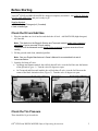
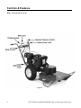
1
DR® ALL-TERRAIN® FIELD and BRUSH MOWER
Safety & Operating Instructions
Please read through these Operating Instructions and the Engine Manufacturer’s Owner's Manual to
become familiar with the basic features of the DR® ALL-TERRAIN® FIELD and BRUSH MOWER
before operating it.
And congratulations on your purchase of a new DR®
FIELD and BRUSH MOWER!
We have done our utmost to ensure that your DR®
FIELD and BRUSH MOWER will be one of the most
trouble-free and satisfying pieces of equipment you
have ever owned. Please let us know of any questions
or problems you may have. We want to answer or
correct them as quickly as possible. (When you do call
or write, please have your serial number and/or order
number handy—it will speed things up!) We also hope
to hear from you on how much you like your new
helper.
And, please tell your friends about your new DR®
FIELD and BRUSH MOWER! Having DR® Owners
spread the word about our products and our way of
doing business is the best advertising we can have, and
the best way to help us provide even better service in
the years to come.
Thanks once again!
for all of us at...
COUNTRY HOME PRODUCTS®
We Want You to be Totally Satisfied
The DR® FIELD and BRUSH MOWER is designed to provide year after year of trouble-free
performance. To ensure that you are totally satisfied with this important purchase, we offer the
following three-part Assurance of Satisfaction:
1. THE DR® FIELD and BRUSH MOWER is GUARANTEED FOR ONE FULL YEAR against
defects in materials and workmanship in consumer use. If you believe that a part is defective,
please write or call us immediately. We will do our best to remedy the problem, including
repairing or replacing defective parts as quickly as possible. In rental and commercial use the
machine is guaranteed for 90 days. The engine is guaranteed separately by the manufacturer:
Kawasaki Engine: Two years in consumer use, two years in commercial use.
Tecumseh Engine: Two years in consumer use, one year in commercial use.
Briggs & Stratton 10.5 HP Engines: Two years in consumer use, one year in commercial use.
Briggs & Stratton 8.0 HP Engines: Two years in consumer use, 90 days in commercial use.
2. IF WITHIN THE FIRST 30 DAYS of actual hands-on use you have questions or you are less
than 100% satisfied with your DR® FIELD and BRUSH MOWER, please write or call us at 1800-DR-OWNER (376-9637). We'll do everything possible to answer your questions or make
things right—even if it means that you return your DR® FIELD and BRUSH MOWER for a full
refund of its purchase price, shipping costs included. (Refund on shipping is for standard
method, and applies to the contiguous United States and Canada only.)
3. We operate, for our Owners, a 7-Day-a-Week Customer Service Department with well-trained
and friendly folks whose sole job it is to ensure that you get any help you need...parts that need
to be replaced...or questions answered courteously and as promptly as possible.
For future reference when dealing with your warranty, save the packing list from the outside of
the DR® FIELD and BRUSH MOWER box and keep it in a safe place. Also, please fill out the
information below.
Name Purchased Under: _____________________________________________
Order Number: __________________ Serial Number: ____________________
Date Purchased: _____/_____/_____
Table of Contents
SAFETY INFORMATION................................................................................................................................................3
DRESS APPROPRIATELY ....................................................................................................................................................3
PREPARATION ...................................................................................................................................................................3
OPERATING THE MACHINE SAFELY ..................................................................................................................................3
WARNING TO ALL CALIFORNIA AND OTHER USERS .........................................................................................................4
BEFORE STARTING ........................................................................................................................................................5
CHECK THE OIL AND ADD GAS .........................................................................................................................................5
CHECK THE TIRE PRESSURE..............................................................................................................................................5
CONTROLS & FEATURES .............................................................................................................................................6
OPERATING INSTRUCTIONS.......................................................................................................................................7
BEFORE STARTING THE ENGINE........................................................................................................................................7
STARTING THE ENGINE .....................................................................................................................................................7
ENGAGING THE WHEEL DRIVE .........................................................................................................................................7
ENGAGING THE BLADE .....................................................................................................................................................7
STOPPING THE BLADE .......................................................................................................................................................8
STOPPING THE ENGINE......................................................................................................................................................8
LOCKING THE WHEEL DIFFERENTIAL ...............................................................................................................................9
SLOPES .............................................................................................................................................................................9
IF THE MACHINE GETS HUNG UP... ...................................................................................................................................10
CUTTING BRUSH & SAPLINGS ........................................................................................................................................10
REVERSE.........................................................................................................................................................................10
CUTTING IN WET & HEAVY GROWTH ............................................................................................................................10
ENGINE MAINTENANCE............................................SEE ENGINE MANUFACTURER'S OWNER'S MANUAL
GENERAL MAINTENANCE ......................................................................................................................................... 11
LUBRICATION .................................................................................................................................................................11
BATTERY ........................................................................................................................................................................13
BELTS .............................................................................................................................................................................14
BLADE ............................................................................................................................................................................17
DIFFERENTIAL ................................................................................................................................................................18
DRIVE CHAIN..................................................................................................................................................................19
WHEEL CLUTCH .............................................................................................................................................................20
BLADE ENGAGEMENT CABLE .........................................................................................................................................21
TRANSMISSION ...............................................................................................................................................................21
TO REMOVE THE WHEELS ..............................................................................................................................................21
END OF SEASON & STORAGE....................................................................................................................................22
TROUBLESHOOTING ...................................................................................................................................................23
PARTS LIST .....................................................................................................................................................................25
MAIN FRAME ASSEMBLY...........................................................................................................................................27
WHEEL/AXLE ASSEMBLY ..........................................................................................................................................28
HANDLEBAR ASSEMBLY............................................................................................................................................29
BRUSH MOWER DECK ASSEMBLY..........................................................................................................................30
WIRING DIAGRAMS .....................................................................................................................................................31
DAILY CHECK LIST FOR THE DR® FIELD AND BRUSH MOWER............................................. BACK COVER
DR® FIELD and BRUSH MOWER Safety & Operating Instructions
1
2
DR® FIELD and BRUSH MOWER Safety & Operating Instructions
Safety Information
We want you to enjoy years of productive use from your DR® FIELD and BRUSH MOWER. We
don't want you to get injured, so please take a few moments to read the following guidelines for
safely operating your new machine.
Dress Appropriately
· Wear safety glasses while mowing to protect your eyes from thrown objects.
· Wear shoes with non-slip treads when using your DR® FIELD and BRUSH MOWER. If you
have safety shoes, we recommend that you wear them. Do not use the machine while barefoot or
wearing open sandals.
· Wear long pants while mowing, and avoid loose clothing or jewelry, which might get caught in
brush or on the mower's moving parts.
· Use ear muffs or ear plugs to protect your valuable hearing.
· We recommend wearing gloves while mowing.
Preparation
· Read these Safety & Operating Instructions as well as the engine manufacturer's owner's manual
before you use the DR® FIELD and BRUSH MOWER. Become familiar with the controls,
engine and service recommendations to ensure the best performance from your machine.
· Inspect the area you'll be working in for hidden objects such as large rocks, logs, rope, wire,
garden tools, etc., and remove these obstacles before mowing. Mowing over such obstacles
could damage the machine and cause injury.
· Mow only during the daylight hours.
· Fill the gasoline tank outdoors with the engine off. Don't handle gasoline if you or anyone
nearby is smoking, or if you're near anything that could cause it to ignite or explode.
Operating the Machine Safely
· Keep bystanders at least 100 feet away from your work area at all times. Objects can be thrown
far from the mower and at great speeds. To be safe, do not operate the machine near small
children or pets, and never allow children to operate the mower. Disengage the blade and stop
the engine when another person approaches.
· Be sure all blade and wheel controls are DISENGAGED before attempting to start the engine.
Engage and disengage the blade a few times to get used to it before mowing.
· NEVER remove the shields from the mower, or alter the deck in any way.
· Keep your hands and feet away from the blade, belts, chains, blade pulleys, and concealed areas
while the engine is running. NEVER reach under the deck or grab hold of the deck deflector
when the engine is running.
· ALWAYS shut off the engine and remove the spark plug wire prior to making any adjustments
to the machine. If you have to stop to remove grass or debris from the underside of the deck,
always disconnect the spark plug wire first.
DR® FIELD and BRUSH MOWER Safety & Operating Instructions
3
· The exhaust area on the engine becomes very hot. Allow the engine to cool before doing
maintenance or making adjustments.
· Keep combustible substances away from the engine when it is hot.
· When operating over uneven terrain and slopes, use EXTREME CAUTION and make sure
you're on firm footing at all times.
· Use extra caution when mowing in wet, slippery conditions.
· ALWAYS OPERATE THE MOWER FROM BEHIND. Never pass or stand on the discharge
(right) side or in front of machine when the engine is running.
· DO NOT, under any conditions, remove, cut, bend, weld or otherwise alter standard parts on
your DR® FIELD and BRUSH MOWER. This includes all shields and guards. Unauthorized
modifications can make the equipment unsafe and may void your warranty.
· While using the DR® FIELD and BRUSH MOWER, don't hurry or take things for granted.
When in doubt about the equipment or your surroundings, stop the machine and take the time to
look things over. Make sure that you have 100% control of the mower at all times.
· Some state and local regulations require the use of a spark arrester on gas powered
engines. Contact your local fire marshal or forest service for specific information
pertaining to your area. If you are required to use a spark arrester, please contact one of
our Customer Service Representatives TOLL FREE 1(800)DR-OWNER (376-9637) for
assistance in obtaining and installing one.
Warning to All California and Other Users
Under California law, and the laws of some other states, you are not permitted to operate an internal
combustion engine using hydrocarbon fuels without an engine spark arrester. All DR® FIELD and
BRUSH MOWERS shipped to California and Washington state are provided with spark arresters.
Failure of the owner/operator to maintain this equipment in compliance with state regulations is a
misdemeanor under California law and may be in violation of other state and/or federal regulations.
Contact your local fire marshal or forest service for specific information in your area.
4
DR® FIELD and BRUSH MOWER Safety & Operating Instructions
Before Starting
Your DR® FIELD and BRUSH MOWER is shipped completely assembled. Just CHECK THE OIL
LEVEL AND ADD GAS, and you're ready to go!
Supplies Needed:
· SAE30 HD (High Detergent) oil (if needed)
· fresh unleaded gas
Check the Oil and Add Gas
1. Place the machine on a level surface and check the oil level. Add SAE30 HD (high detergent)
oil if needed.
Note: The dipstick on the Briggs & Stratton and Tecumseh models needs to be screwed in
completely to get an accurate oil level reading.
The dipstick on the Kawasaki model should not be screwed in to get an accurate oil level
reading.
2. Fill the gas tank with clean, unleaded gasoline.
Note: See your Engine Manufacturer's Owner's Manual for more detailed fuel and oil
recommendations.
3. Open the fuel shut-off valve.
· On Briggs and Stratton models, the red fuel shut-off valve is on the fuel line near the bottom
of the gas tank (Figure 1). Turn the valve 90 degrees to open.
· On Tecumseh and Kawasaki models, the red fuel shut-off valve is on the fuel line near the
corner of the black chain drive box (Figure 2). Turn the valve 90 degrees to open.
Figure 1
Figure 2
Check the Tire Pressure
There should be 14 psi in each tire.
DR® FIELD and BRUSH MOWER Safety & Operating Instructions
5
Controls & Features
Note: Kawasaki Model shown.
Figure 3
6
DR® FIELD and BRUSH MOWER Safety & Operating Instructions
Operating Instructions
Before Starting the Engine
1. Check the oil level every time you use the machine.
2. Check the gas level.
3. Open the fuel shut-off valve.
Starting the Engine
Electric-Starting
1. Move the throttle to the CHOKE position (to the RUN position if the engine is already warm).
2. Turn the key to START and hold it until the engine starts.
3. Release the key, it will snap to the RUN position.
4. Move the throttle to the RUN position.
Manual-Starting (ATM10S Briggs & Stratton Model only)
1. Move the throttle to the CHOKE position (to the RUN position if the engine is already warm).
2. Turn the key to START.
3. Pull the recoil rope slowly until you feel resistance, then pull with a rapid stroke to start the
engine.
4. Move the throttle to the RUN position.
Engaging the Wheel Drive
The DR® FIELD and BRUSH MOWER has a four-speed forward transmission and single-speed
reverse. Forward speeds range from 1.4 mph in first gear to 4.3 mph in fourth gear. Use the lower
gears for mowing in thick, woody vegetation and the higher gears for wide-open areas and lighter
vegetation, or as "travel gears." Reverse is ideal for maneuvering in tight spots.
Note: Always release the wheel clutch lever when shifting gears.
1. Move the shift lever to the desired gear.
2. Gently squeeze the wheel clutch lever to engage a gear.
Engaging the Blade
1. Hold down the operator presence lever.
2. Engage the blade control lever.
Note: If you engage the blade control lever before holding down the operator presence
lever the engine will shut off.
DR® FIELD and BRUSH MOWER Safety & Operating Instructions
7
Stopping the Blade
Push the blade control lever forward to OFF.
Note: Releasing the operator presence lever while the blade is engaged will cause the
engine to shut off.
Stopping the Engine
1.
2.
3.
4.
8
Push the blade control lever forward to OFF.
Move the shift lever to N (neutral).
Move the throttle control to IDLE.
Turn the key to OFF and remove it for safety.
DR® FIELD and BRUSH MOWER Safety & Operating Instructions
Tips for Best Performance
Locking the Wheel Differential
In rough or wet terrain, or on moderate
slopes, you can lock the wheel differential,
so both wheels turn together with improved
traction.
To lock the wheel differential, move the
lever between the lower handlebars to the
right (Figure 4).
Note: When mowing with the wheel
differential locked you may find it more
difficult to turn and maneuver.
Slopes
· We do not recommend using the DR®
Figure 4
FIELD and BRUSH MOWER continuously on slopes greater than 25 degrees. Doing so could
deprive the engine of oil and cause it to overheat.
· When moving across moderate slopes, in
ditches, etc., locking the differential will
improve traction (Figure 6).
· Note that the mowing deck pivots from side
to side (12 degrees in either direction),
which helps avoid scalping, and keeps the
weight balanced over the drive wheels when
operating on uneven terrain (Figure 5).
· Please read the safety information beginning
on page 1.
Figure 5
®
DR FIELD and BRUSH MOWER Safety & Operating Instructions
Figure 6
9
If the machine gets hung up...
· Disengage the blade. Do not try to free
the machine from stumps or debris while
the blade is engaged.
· Try putting the machine in reverse and
backing away from the obstacle.
· Try pushing down on the handlebars to lift
the mowing deck over the obstacle
(Figure 7).
· If you need to leave the operating position,
first put the machine in "N" (neutral), turn
the engine off and disconnect the spark
plug wire.
Figure 7
Caution: DO NOT touch the exhaust
areas when reaching for the spark plug—they are very hot.
Cutting Brush & Saplings
· When cutting woody material, small
saplings, etc., allow the machine to ride
up and over material slowly. Adjust
your forward speed to varying conditions
(Figure 8).
· After cutting brush, etc., you may want
to mow over it again to remove any
remaining branches. It works best to
mow from the trunk end toward the top
as brush lies on the ground.
Reverse
· Be very careful of your footing when
Figure 8
operating the machine in reverse. Know
what's behind you and take your time.
· The blade will engage in reverse, however, we don't recommend continuous mowing in reverse.
Mow in the forward gears, using reverse for maneuvering.
· If you find it difficult to shift into reverse, lightly "feather" the clutch lever as you pull the shift
lever into reverse, then quickly release the clutch lever.
Cutting in Wet & Heavy Growth
· Be very careful of your footing when mowing in wet conditions. Avoid steep slopes and other
slippery areas.
· Use a lower, slower speed.
10
DR® FIELD and BRUSH MOWER Safety & Operating Instructions
General Maintenance
For Engine Maintenance, Please Refer to the Engine
Manufacturer's Owner's Manual.
IMPORTANT: Because of the demanding conditions the DR® ALL-TERRAIN™ FIELD
and BRUSH MOWER is used in, air filters and oil should be changed more frequently
than is recommended in your Engine Manufacturer's Owner's Manual. Please follow
these recommendations:
Paper Air Filter: Should be replaced every 25 hours of operation.
Oil: Should be drained and replaced every 25 hours of operation.
Regular maintenance ensures the best performance from your machine. Follow these
instructions as well as the recommendations in the Engine Manufacturer's Owner's Manual
to keep your DR® FIELD and BRUSH MOWER in top condition. Use the daily checklist on
the back cover of this manual whenever you operate your mower.
!
WARNING: Some of the following procedures require access to the underside of the
machine. Before you tip the machine on its side with the discharge chute facing up, you must
drain the oil and gas, and remove the air filters.
Lubrication
Your DR® FIELD & BRUSH MOWER is greased at the factory. You do not need to lubricate it for
the first 25 hours of use.
Tools Needed:
· flexible hose grease gun
· Lithium grease
· FLUID FILM® or WD-40® lubricant
!
WARNING: Always remove the spark
plug wire before servicing your machine.
Grease Fittings
1. There are three grease fittings below the
black belt guard that need maintenance:
· The mower pivot tube (Figure 9)
should have 1-2 pumps of grease every
25 operating hours.
· The belt idler arm (Figure 9) should
have 1-2 pumps of grease every 25
operating hours.
Figure 9
®
DR FIELD and BRUSH MOWER Safety & Operating Instructions
11
·
The mower spindle (Figure 10) should
have 3-4 pumps every 100 operating
hours.
Note: Over greasing will cause grease
to leak out of the seals onto the mower
drive belt. Unless instructed otherwise,
pump only until you feel slight
resistance (1-2 pumps).
Figure 10
2. The following areas should be lubricated with FLUID FILM® or comparable lubricant every 10 to
20 operating hours—more often if the machine is operated in extremely dusty conditions:
· The differential fork at both ends (Figure 11).
· The axle above the hub where the spring is (Figure 11).
· The drive chain and the chain adjuster slide plate (Figure 12).
Figure 11
12
Figure 12
DR® FIELD and BRUSH MOWER Safety & Operating Instructions
Battery
Electric-Starting Models
Proper care can lengthen the life of a battery. Follow these recommendations to ensure your
battery's best performance and long life:
· Do not allow the battery charge to get too low. If the machine is not used, the battery should be
charged every 4 – 6 weeks.
· Store an unused battery in a dry area that does not freeze.
· Do not charge an already charged battery. In theory, our battery can not be overcharged with a
trickle charger; however, when a battery is fully charged and the charger is still on, it generates
heat that could be harmful to the battery. A fully charged battery will read 12V-13.2V with a
voltmeter.
· Do not continue to crank your engine with a low battery.
Charging the Battery
If the battery loses its charge, you'll need to use a trickle charger (like the DR® Battery Charger) to
recharge it. The charger should have an output of 12 volts at no more than 6-8 amps.
· At 1 amp the battery may need to be charged for as much as 48 hours.
· At 2 amps the battery may need to be charged for as much as 24 hours.
· At 6-8 amps the battery will be charged in 2 to 3 hours.
Caution: At 6-8 amps a battery can overcharge.
Note: Using the recoil starter (ATM10E Briggs & Stratton model only) and then running the engine
will not recharge a dead battery.
DR® FIELD and BRUSH MOWER Safety & Operating Instructions
13
Belts
To Remove the Blade Belt
Tools Needed:
· 1/2" socket with extension
· 1/2" wrench
· vise grip pliers
!
WARNING: Always remove the spark
plug wire before servicing your machine.
1. Remove the black belt guard: Unscrew
the black knob, lift the cover and pull up
and back to remove it.
2. Using a 1/2" wrench or socket, remove
the lock nut on the anti-rotation strap
and pull the strap away from the post
(Figure 13).
3. Rotate the clutch counterclockwise to
release the tension on the blade clutch
spring.
4. Remove the blade clutch spring (Figure
14). Remove the extension spring
(Figure 16). You can use vise grip
pliers to remove the spring or make a
simple wire pull as illustrated in Figures
15 & 16.
Figure 13
Caution: The extension spring (Figure
16) has considerable tension.
Figure 14
Figure 15
14
Figure 16
®
DR FIELD and BRUSH MOWER Safety & Operating Instructions
5. Remove the 5/16" x 2" cap screw from the
pivot tube (Figure 17).
6. Push the deck back to create slack on the
belt. Then pull the belt forward and drop
it down off the blade clutch pulley.
7. Twist the other end of the belt and drop it
off the 3" engine pulley (Figure 18).
8. Remove the belt.
To Replace the Blade Belt
Tools Needed:
· 1/2" socket with extension
· 1/2" wrench
· vise grip pliers
!
Figure 17
WARNING: Always remove the spark
plug wire before servicing your machine.
1. Keep the mower deck back and mount
the new belt over the two pulleys
(Figures 17 & 18).
2. Pull the mower deck forward.
3. Push the pivot washer back toward the
engine (it should be between the cap
screw and the frame).
4. Replace the 5/16" x 2" cap screw on the
pivot tube (Figure 17). Tighten until you
see 3-4 threads outside of the nut—do not
over tighten.
Figure 18
Note: If you can't get the cap screw
through the pivot tube, you can use a
piece of wood to push the deck forward
so the holes line up (Figure 19).
5. Replace the extension spring (Figure 16).
6. Replace the blade clutch spring
(Figure 14).
7. Replace the anti-rotation strap
(Figure 13).
Note: Only turn the nut on the antirotation strap until one or two threads
show—it is not meant to be tightened
down.
8. Replace the black belt guard and screw
the black knob into place.
DR® FIELD and BRUSH MOWER Safety & Operating Instructions
Figure 19
15
To Remove the Drive Belt
Tools Needed:
· 7/16" socket
· 1/2" socket
· 5/8" wrench
!
WARNING: Always remove the spark
plug wire before servicing your machine.
1. Drain the oil and gas and remove the air
filters.
2. Remove the black belt guard. Unscrew
the black knob, lift the cover and pull
back and up to remove it.
3. Remove the blade belt. (Follow the
instructions on page 14.)
4. Turn the machine onto its left side, with
the discharge chute facing up.
5. With a 7/16" socket, remove the two belt
retainers from the 6" transmission pulley.
There is one on the rear of the pulley and
one on the side (Figure 20). Be careful not
to lose the retainers or washers.
6. With a 1/2" socket, loosen the two lock
nuts that hold the belt guide (2-3 turns,
don't remove them) and pull the belt guide
back (Figure 21).
7. Push the 2-1/4" clutch idler pulley to the
outside of the frame and start guiding the
belt off the 6" transmission pulley. Using a
5/8" wrench (on the Kawasaki use a 14mm
wrench), rotate the crankshaft bolt on the
engine clockwise (counterclockwise on the
Briggs & Stratton manual-starting engine)
while continuing to guide the belt off
(Figure 22).
Figure 20
Figure 21
Figure 22
16
DR® FIELD and BRUSH MOWER Safety & Operating Instructions
To Replace the Drive Belt
Tools Needed:
· 7/16" socket
· 1/2" socket
· 5/8" wrench
!
WARNING: Always remove the spark plug wire before servicing your machine.
1. Mount the new belt over the 6" transmission pulley (Figure 22).
2. Place the belt in the belt guide and slide the belt guide forward, making sure it is under the flat
washers. Position the belt with a 1/16" to 1/8" space between the pulley and the belt guide.
Tighten the belt guide (Figure 21).
3. Replace the two belt retainers and washers on the 6" transmission pulley (Figure 20).
4. Reinstall the blade belt. (See the instructions on page 15.)
5. Turn the machine upright.
Note: You may need to adjust the wheel clutch cable after replacing the belt. See the instructions
on page 20.
Blade
To Replace the Blade
Tools Needed:
· 15/16" wrench or socket
· air wrench if available
· rag or gloves to handle the blade
!
WARNING: Always remove the spark
plug wire before servicing your machine.
Note: You may need a length of pipe to fit
over the wrench for more leverage when
removing the blade nut.
1. Block the blade with a piece of wood
between the blade and the skid on the
chute side of the deck (Figure 23).
2. Remove the blade lock nut (right-hand,
regular thread) and washer.
Caution: Be careful not to get cut when
pushing or pulling the wrench next to the
blade.
3. Remove the blade.
DR® FIELD and BRUSH MOWER Safety & Operating Instructions
Figure 23
17
4. Mount the new blade, washer and lock
nut.
Note: Be sure the blade is seated
completely over the small ridge in the
spindle hub before tightening the lock
nut (Figure 24).
Figure 24
Differential
It is important to keep the differential parts lubricated. See page 12 for maintenance instructions.
To Adjust the Differential
If the differential locks while in the disengaged position, follow the instructions below to adjust it.
Tools Needed:
· (2) 1/2" deep well wrenches or sockets
· screwdriver
!
WARNING: Always remove the spark
plug wire before servicing your machine.
1. Loosen the bolt in Figure 25 about 1/2
turn.
2. With a screwdriver, push the shift
support toward the axle as far as it will
go and tighten the bolt (Figure 25).
3. Engage and disengage the differential
lever a few times, then check the
clearance between the hub sleeve and the
hub bell. There should be 1/8" clearance
when the lever is disengaged (Figure
26).
4. If needed, adjust the nut in Figure 26 and
repeat steps 3 and 4 to get the proper
measurement.
Figure 25
Figure 26
18
DR® FIELD and BRUSH MOWER Safety & Operating Instructions
Drive Chain
To Adjust the Drive Chain
This adjustment should be done after the 1st , 3rd, 5th and 10th hours of use, then every
subsequent ten hours of use, to remove any slack or looseness from the chain.
Tools Needed:
• (2) 1/2" wrenches
!
WARNING: Always remove the
spark plug wire before servicing your
machine.
1. Loosen the outer nut on the chain
adjustment bolt so you can access the
inner nut (Figure 27).
2. Tighten the inner nut by hand or with a
1/2" wrench until it is snug against the
frame (Figure 27).
3. With the machine in Neutral, roll it back
and forth several times to remove any
play in the chain, then recheck the
adjustment. When you push in the center
of the chain it should not move more than
Figure 27
1/2".
4. When the adjustment is correct, with two 1/2" wrenches, hold the inner nut in place and tighten
the outer nut firmly against it.
5. Check and tighten the innermost nut on the adjustment bolt (look under the machine, it's the nut
that sits against the chain adjuster bracket). This nut must be tight against the bracket.
IMPORTANT!: DO NOT try to adjust the chain adjustment bolt—only the three nuts.
To Replace the Drive Chain
Tools & Supplies Needed:
· Chain: Part #131081
· 7/16" wrench
· flat-head screwdriver
· pliers
!
WARNING: Always remove the spark
plug wire before servicing your machine.
1. Remove the lock nuts from the access
door and remove it (Figure 28).
Note: On the Kawasaki and Tecumseh
engines you'll need to move the fuel line and
clamps off the studs before removing the
access door.
®
DR FIELD and BRUSH MOWER Safety & Operating Instructions
Figure 28
19
2. Loosen (don't remove) the chain drive
adjustment bolt See instructions on Page
19. This will take tension off the chain
and make it easier to remove.
3. Remove the master chain link (Figure 29).
First remove the lock clip (A) with a flathead screwdriver and pliers. You'll need
to lift one side and rotate the clip to get it
off the master link. Next remove the side
plate (B). Then remove the master chain
link.
4. Slowly feed the chain out.
5. Mount the new chain.
6. Add the master chain link.
7. Replace the access door and tighten the lock nuts.
8. Readjust the chain drive adjustment bolt (page 19, Figure 27).
Figure 29
Wheel Clutch
When properly adjusted, tension on the wheel clutch lever should increase when the lever is about
parallel to (almost touching) the handlebar
grip.
Tools Needed:
· 7/16" wrench
!
WARNING: Always remove the spark
plug wire before servicing your machine.
1. Find the wheel clutch adjustment cap
screw on the right side of the frame near
the oil drain plug (Figure 30).
2. Loosen the cap screw 1/2 to 1 turn. Slide
it back in the slot to tighten the clutch
lever then tighten the cap screw.
Figure 30
20
DR® FIELD and BRUSH MOWER Safety & Operating Instructions
Blade Engagement Cable
If the blade won't cut, or seems to slip in
heavy material, check the blade engagement
cable. Remove the black belt guard and
measure the length of the blade clutch spring
(the spring that attaches the cable to the
blade clutch) (Figure 31). When the blade is
engaged (lever pulled back) the spring
should measure 3-1/2" to 3-3/4".
Note: Do not adjust the spring longer than
3-3/4".
Tools Needed:
· 1/2" open-end wrench
!
WARNING: Always remove the spark
plug wire before servicing your machine.
Figure 31
1. On the right handlebar there is a bracket
with two nuts (one on each side) for
adjusting the blade engagement cable
(Figure 32). Loosen the nuts and push
the threaded cable housing down about
1/8" at a time into the bracket. Check the
spring measurement again and adjust as
needed.
2. Retighten the nuts.
Transmission
The transmission is maintenance-free and
does not need additional lubrication.
Figure 32
To Remove the Wheels
Tools Needed:
· flat head screwdriver
!
WARNING: Always remove the spark
plug wire before servicing your machine.
1. Block the machine so the wheel to be
removed is off the ground.
2. Rotate the tire so the key slot is facing
upwards.
3. Use the screwdriver to remove the Ushaped lock ring (Figure 33), remove the
washer and slide the wheel off.
Figure 33
Note: Be careful not to lose the key.
DR® FIELD and BRUSH MOWER Safety & Operating Instructions
21
End of Season & Storage
!
WARNING: Always remove the spark plug wire before servicing your machine.
Please refer to the Engine Manufacturer's Owner's Manual for engine-specific procedures.
· Change the oil.
· Remove the spark plug and pour about 1 ounce of motor oil into the cylinder hole. Replace the
plug and pull the recoil starter rope until you feel strong resistance. This will coat the piston and
seat the valves to prevent moisture buildup.
· Clean/replace the air filters.
· Clean dirt and debris from the cylinder head cooling fins, blower housing, debris screen and
muffler area of the engine.
· If your engine has a fuel filter, replace it.
· If your DR® FIELD and BRUSH MOWER will be idle for more than 30 days, we recommend
using a gas stabilizer. This will prevent the carburetor from gumming up. If there is dirt or
moisture in the gas, remove it by draining the tank. Completely fill the tank with fresh, unleaded
gas and add the appropriate amount of stabilizer or gasoline additive. Run the engine for a short
time to allow the additive to circulate. Close the gas shut-off valve to prevent carburetor
overflow and leakage.
· Store the battery in a dry area that does not freeze. If the machine is not used over a long period,
the battery should be charged every three months. See page 13.
· Remove any wrapped weeds from the blade bearing housing. Clean grass and debris from the
top and underneath the mower deck with a stiff brush.
· Check the blade for nicks and wear. Remove the blade and sharpen, or have it professionally
sharpened if needed.
22
DR® FIELD and BRUSH MOWER Safety & Operating Instructions
Troubleshooting
!
WARNING: Always disengage the blade, turn off the engine and remove the spark plug
wire before servicing your machine.
Please refer to the Engine Manufacturer's Owner's Manual for specific engine maintenance
and troubleshooting information.
Belts
The belt frays or rolls over the pulley
Þ A pulley groove may be nicked. Check the belt
for wear and hard spots. File off any nicks on the
pulley.
Þ The belt may be stretched. Replace it.
Blade
The cut material is not being properly discharged out
of the right side of the machine
Þ The discharge may be blocked. Disengage the
blade, turn off the engine, disconnect the spark
plug and check for debris.
Heavier growth gets hung up under machine and
does not discharge
Þ Try removing the baffle under the front of the
mowing deck.
The blade is not cutting or is loose
Þ The blade may not be seated properly. Loosen
the blade nut, reset the blade and tighten the nut.
Differential
Differential locks when not in engaged position
Þ Follow the adjustment instructions on page 18.
Engine
Recoil will not pull out or is difficult to pull. (Briggs &
Stratton Engine, Models ATM10S and ATM10E only)
Þ Check that the blade lever is in the disengaged
position.
Þ The recoil may be broken or jammed. Try to turn
the engine pulley by hand, with the spark plug
wire off. If it turns, the recoil is broken or
jammed.
Engine won't start
Þ Check for adequate, fresh fuel.
Þ Check that the fuel valve is turned on.
Þ Check the fuel filter to see if it is clear. Remove
the line from the engine side of the filter. If gas
flows freely, it’s OK.
Þ Check the throttle adjustment and travel.
Þ Is the blade engagement lever down
(disengaged)? It should be.
Þ Check the spark plug.
Þ Tecumseh and Kawasaki engines have a 10 amp
fuse on the wiring harness. Check the fuse and
replace if needed.
Electric-Starting Models:
Þ Check the wire connections—especially the
ground connection, the large green wire coming
from the battery where it connects to the engine.
DR® FIELD and BRUSH MOWER Safety & Operating Instructions
23
Engine won't start (continued)
Þ Check the wire connections to the solenoid.
Disconnect the green battery ground wire first to
avoid sparks. Check to be sure that all of the
connections are tight. Reconnect the battery
ground wire.
Þ Check the ground connection on the solenoid
(ATM10E, 125) where it’s bolted to the frame.
Using a wrench or socket, spin the bolts and
tighten them to ensure a good connection to the
frame.
Engine lacks power
Þ Check the throttle travel and adjustment.
Þ Clean or replace the air filter if needed.
Þ Check the spark plug and replace if needed.
Þ Add clean, fresh, unleaded gas.
Þ Check the oil level and adjust as needed.
Engine skips, pops, misses, shakes
Þ Check the spark plug and replace if needed.
Þ Clean or replace the air filter if needed.
Þ Check the vent holes in the fuel cap — clean
them if they’re clogged.
Þ Replace gas with fresh, unleaded fuel.
Engine smokes
Þ Check the oil level and adjust as needed.
Þ You may be operating the machine on too great
an incline.
Þ Check the air filter and clean or replace if
needed.
Þ You may be using the wrong oil—too light for the
temperature. Refer to your Engine
Manufacturer's Owner’s Manual for detailed
information.
Þ Clean the cooling fins if they’re dirty.
Transmission
Machine is hard to get into reverse
Þ If you find it difficult to shift into reverse, lightly
pull the clutch lever as you pull the shift lever into
reverse then quickly release the clutch lever.
Wheels
Wheels are slipping
Wheels pulling left or right
Þ Try engaging the wheel differential.
Þ Check the tire pressure. There should be 14 psi
in each tire.
For technical assistance call Toll-Free 1(800)DR-OWNER (376-9637).
24
DR® FIELD and BRUSH MOWER Safety & Operating Instructions
Parts List
Please refer to the schematic drawings starting on page 27.
Note: Not all parts listed appear on the drawings.
Ref#
1
Part#
100831
2
100841
3
4
5
6
9
10
10
11
12
13
14
15
16
17
17
18
19
20
21
22
23
24
25
26
27
124511
101341
100861
100851
100971
124521
125071
101261
101401
100731
101001
100471
101011
100481
100491
101511
100411
101771
101411
100231
101731
101721
101571
101311
127471
28
29
30
31
32
33
34
35
36
37
38
39
40
41
42
43
101461
101251
101651
101661
100551
100241
101241
101441
100201
101051
100561
100221
101171
100621
101201
100981
Description
10.5 HP IC B&S Electric-Start
Engine
10.5 HP IC B&S Manual-Start
Engine
Battery Clamp
Battery Pad
12.5 HP OHV TEC Engine
14.0 HP OHV KAW Engine
Main Frame
Handlebar Assembly, Manual
Handlebar Assembly, Electric
Shift Lever
3" Blade Drive Pulley
Brush Deck, 26" (shell only)
Belt Guard
Upper Bearing
Chain Guard
Air Tip Blade 26"
Brush Blade 26"
Spindle Shaft
Spindle Housing Assembly
Blade Washer
Idler Pulley
Clutch Idler Arm
Drive Belt 1/2" x 30"
Blade Belt 5/8" x 56"
Steel Spacer
Blade Lock Nut 5/8"-11
5/16" x 3-1/4" Chain adjuster
bolt
Bolt, HHCS, 5/16" x 1-1/4"
Operator Presence Lever
Momentary Switch BLACK
Momentary Switch RED
Belt Guard Bracket
Shift Rod Arm
Blade Control Lever
Tie Rod
Chain Adjuster
Belt Guide
Cable Adjustment Bracket
Blade Idler Arm
Spindle Hub
Blade Engage Cable
Knob, Belt Guard
Grip, Mower Engagement Lever
Ref#
44
45
46
47
48
49
Part#
100641
101801
101861
101561
101891
135971
50
101551
51
52
53
54
55
56
57
58
59
60
61
62
63
64
106361
100601
100611
101791
101621
100961
101061
101271
101371
101191
100581
101741
101751
130491
65
66
67
68
101501
100591
101471
100441
69
70
71
72
73
74
75
77
79
80
81
82
83
84
85
86
100451
100461
100431
101871
101841
101831
101851
101821
100761
101021
101431
100671
101671
100211
100721
100571
87
101521
Description
Cap, Mower Engagement Lever
Nylon Washer 1" x .505" x .125"
Positive Wire, KAW, 23" Red
Spacer .75" x 1" x 1.7"
Grease Fitting 1/4"-28
Flexible Conduit, Split - 7/16" X
30"
Solenoid - Briggs electric,
Tecumseh
Key, 1/4" x 1/4" x 2-1/4"
Bushing 1/2" OD x 3/8" ID
Idler Arm Bushing
Flat Washer 1/2" ID
Extension Spring 5"
Shift Fork
Shift Fork Guide
Shift Lever, Differential
Shift Lever Plate
Key 3/16" x 2", SQ.
Blade Clutch Brake
Washer 1-1/2" x .640" x 1/4"
Washer 1-1/2" x .765" x 1/4"
Differential w/Sprocket - 54
tooth
Machine Screw 3/8"-16 x 1-1/2"
Bushing .375" OD x .265" ID
Bolt, HHCS, 5/16" x 2-1/4"
Wire Harness B&S – ElectricStart
Wire Harness KAW
Wire Harness TEC
Wire Harness B&S Manual-Start
Green Safety Switch Wire 15"
Green Negative Wire 23"
Green Negative Wire 16"
Red Positive Wire 20"
Red/Black Alternator Wire 12"
Access Door
Stone Guard
Stone Guard Rod
Belt Guard Clip
Spring Link Switch
Anti-wrap
Deck Baffle
Deck Support Bracket (Brush
Deck)
Pivot Shim
DR® FIELD and BRUSH MOWER Safety & Operating Instructions
25
Ref#
88
90
Part#
101631
131081
91
91
92
93
94
95
96
97
98
99
100
101
102
103
104
105
106
107
110601
110591
136851
101811
101451
101681
100631
100941
101301
123451
101711
100661
101321
101761
101601
100771
100501
101701
107
108
109
110
111
112
113
114
115
116
117
118
119
127111
109421
108921
108931
110281
112461
110921
131111
106381
129781
112371
112381
110251
110491
110241
110691
110781
110681
109581
110871
110731
110751
110761
111281
110971
110961
111441
114701
121
123
124
125
126
127
128
129
130
131
132
133
134
135
26
Description
Anti-Rotation Strap
Drive Chain, #41, w/Link & 1/2,
54 Tooth Sprocket
Master Link #41
1/2 Link #41
Label, Pulley Cover, ATM
Split Lock Washer 1/4"
Bolt, HHCS, 1/4" x 1-1/2"
6 Qt. Fuel Tank
Fuel Cap - Tecumseh/Kawasaki
Fuel Filter
Fuel Tank Mount
Fuel Line
Shut-Off Valve
Fuel Line Clamp
Lock Nut 5/16"-24
Washer 1.25" OD
Blade Clutch Spring 2-3/4"
E Clip
Carriage Bolt 5/16"-18 x 1/2"
Transmission 4 Speed w/
Sprocket
Sprocket Only
Clutch Cable Assembly
Bearing Flange, 2" Hole
Ball Bearing 3/4" Bore
Handle, Brake/Clutch
Nylon Washer, .39 ID x 1 OD
Cotter Pin 1/16" x 3/4"
Tire/Wheel, TERR, 18"
Key 3/16" SQ x 1-1/2"
Steel Shim Set
Flat Washer 3/16"
Flat Washer 1/4"
Handle Grip
Key, Woodruff 3/16" x 3/4"
Handle Grip
Nut 5/16"-18"
Nut 5/16"-24"
Nut 10-32
Clevis
Clevis Pin 1/4" x 5/8"
Nylon Lock Nut 1/4"
Nylon Lock Nut 3/8" - 16
Nylon Lock Nut 5/16" - 18
Rod End
Roll Pin, 3/16" x 1-3/4"
Roll Pin 3/16" x 1"
Bolt, HHCS, 1/2" x 2"
Bolt, HHCS, 1/4" - 20 x 1/2"
Ref#
136
138
139
140
141
142
143
144
145
146
147
148
149
150
151
152
153
154
155
156
157
158
159
160
161
163
164
165
166
167
168
169
170
171
172
173
174
175
176
177
178
179
Part#
111501
111491
111511
111571
111581
111591
111421
112391
111741
111701
110221
112111
108791
113071
126971
111261
110881
109751
111191
111241
110461
112051
111341
112481
111871
111731
112431
109481
104831
112441
115611
120891
120631
120901
121661
114651
118731
120101
119831
104871
107071
107051
180
181
182
184
185
186
111471
112061
111681
101291
112431
129621
Description
Bolt, HHCS, 1/4" - 28 x 3/4"
Bolt, HHCS, 1/4" x 1"
Bolt, HHCS, 3/8" x 1-1/2"
Bolt, HHCS, 5/16" x 1-3/4"
Bolt, HHCS, 5/16" x 1"
Bolt, HHCS, 5/16" x 2-1/2"
Bolt, HHCS, 5/16" x 3/4"
Flat Washer 3/8"
Screw 8-32 x 1/2"
Washer 3/8"
Shift Handle Grip
Throttle Control
Shift Arm, Transmission
Idler Pulley 2-1/4"
Fender Washer 1/4" x 1"
Wheel Lock Ring
Clevis Pin 3/16" x 1-3/4"
Cotter Pin 1/16" x 1/2"
Transmission Pulley 6"
Snap Ring
Drive Chain Idler, 10 tooth
Electric-Start Key Switch
Cap Screw 7/16" x 3/4"
Star Lock Washer 1/4"
Spacer 1/4" x 1"
Screw 5/16" x 1/2"
Split Lock Washer 5/16"
Round Cap 1"
Battery, 12 volt
Nylon Washer 1/2" ID x 3/4" OD
Clip
Switch Spring 1-1/8" long
Bushing 1/4"
Compression Spring 1"
Nylon Washer 1/4" ID, .20 Thick
Full Thread Cap Screw 3/8" x 3"
Lock Nut 10-24
Pan Head Screw 10-24
Cap Screw 1/4" x 3/4"
Lower Bearing
Bolt, HHCS, 3/8" -16 x 1", w/Nut
Bolt, HHCS, 5/16" -18 x 3/4",
Gr5
Bolt, HHCS, 1/4" x 1 1/4"
Manual-Start Key Switch
Set Screw 1/4" - 20 x 1/4"
Differential Lock Spring
5/16" Split Lock Washer
Spacer
DR® FIELD and BRUSH MOWER Safety & Operating Instructions
Main Frame Assembly
Please Note: The circled numbers match the first column of numbers on the parts list.
Figure 34
DR® FIELD and BRUSH MOWER Safety & Operating Instructions
27
Wheel/Axle Assembly
Please Note: The circled numbers match the first column of numbers on the parts list.
Figure 35
28
DR® FIELD and BRUSH MOWER Safety & Operating Instructions
Handlebar Assembly
Please Note: The circled numbers match the first column of numbers on the parts list.
Figure 36
DR® FIELD and BRUSH MOWER Safety & Operating Instructions
29
Brush Mower Deck Assembly
Please Note: The circled numbers match the first column of numbers on the parts list.
Figure 37
30
DR® FIELD and BRUSH MOWER Safety & Operating Instructions
Wiring Diagrams
Electric-starting models only
Kawasaki 14.0 HP
Fig\
Tecumseh 12.5 HP
ure 38
DR® FIELD and BRUSH MOWER Safety & Operating Instructions
31
Wiring Diagrams (cont.)
Electric-starting models only
Figure 39
Briggs & Stratton 10.5 HP
32
DR® FIELD and BRUSH MOWER Safety & Operating Instructions
Notes
Notes
Daily Check List for the DR® FIELD and BRUSH MOWER
4 OIL:
With the machine on a level surface, remove the oil fill cap and
check the oil level. Fill the reservoir according to the dipstick with
SAE30 motor oil.
4 GAS:
Fill the gas tank with clean, fresh unleaded gasoline, making
sure the gas valve on the bottom of the tank is open. Always close the
gas valve when storing your machine.
4 ENGINE:
It is very important to keep the engine clean. Remove
grass and other debris from the engine cooling fins and debris guard.
A dirty engine retains heat and can cause damage to the internal engine
parts.
4 BELTS: Check the belts for wear, proper alignment and tension.
4 BLADE: Check the blade for tightness, nicks and wear. Remove any
wrapped weeds and grass from the blade bearing housing to prevent
buildup.
COUNTRY HOME PRODUCTS®
Meigs Road, P.O. Box 25, Vergennes, Vermont 05491
TOLL-FREE 1(800)DR-OWNER (376-9637)
©1999 CHP, Inc. 138341
CODE# 30162X