1
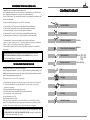
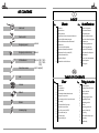
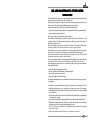
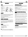
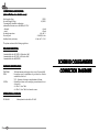
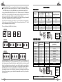
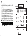
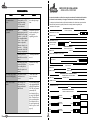
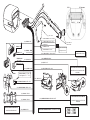
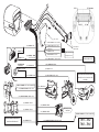
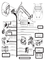
®
C A R S E C U R I T Y
○ ○ ○ ○ ○ ○ ○ ○ ○ ○ ○ ○ ○ ○ ○ ○ ○ ○ ○ ○ ○ ○
ATTENZIONE !
CONSERVATE IL PIN (Codice di Identificazione Personale) insieme alla patente di guida VI SERVIRÀ PER DISINSERIRE IL
SISTEMA IN CASO DI EMERGENZA e per accedere alla procedura di autoapprendimento dei telecomandi.
MANUALE INSTALLAZIONE E UTENTE
FITTING INSTRUCTION AND USER MANUAL
EMERGENCY KEY CARD
PIN CODE =
ON 3 SEC.
ON
a
OFF
OFF
ON
IGN
ON
+
OFF
OFF
ON
IGN
ON
+
PIN
OFF
OFF
ON
=
OK
IGN
MAX 7 SEC.
ATTENTION !
KEEP THE PIN (Personal Identification Number) together with your
personal documents. THE PIN IS REQUIRED IF YOU NEED TO
DISARM THE SYSTEM in emergency condition and to add or change
radio remote controls to the system
○ ○ ○ ○ ○ ○ ○ ○ ○ ○ ○ ○ ○ ○ ○ ○ ○ ○ ○ ○ ○ ○
allarme compatto BRIDGE
BRIDGE compact alarm
Cod. 06DE1250C del 05/98
R
LA PROTEZIONE TOTALE DELLA VOSTRA AUTO
Congratulazioni per aver acquistato un sistema di allarme Cobra.
Questo prodotto ha superato tutti i più severi test delle Case Automobilistiche e degli Enti assicurativi
per la compatibilità elettromagnetica e la resistenza alle condizioni ambientali.
Utilizza il “Codice Dinamico” che rende impossibile disinserire il sistema registrando e riproducendo il codice
trasmesso dal radiocomando.
R
CONTENUTO DEL KIT
La protezione totale della Vostra vettura, nel caso del 7918, è assicurata da:
1.
2.
3.
4.
5.
Protezione taglio cavi - la sirena suona anche se manca la tensione di batteria della vettura.
Protezione contro l'avviamento del motore - garantita dal sistema automatico di attivazione
Protezione dell’abitacolo - per mezzo di un sensore volumetrico ad ultrasuoni.
Protezione periferica - le porte, il cofano ed il baule sono collegati all’allarme tramite pulsanti
Protezione personale - la funzione panico Vi permette di attivare la sirena dal radiocomando.
Vi raccomandiamo di conservare questo manuale insieme ai documenti della vettura.
A pagina 2 il capitolo “Istruzioni in breve” Vi consentirà di apprendere le funzioni più comunemente
utilizzate, in ogni caso Vi consigliamo la lettura di tutto il manuale d’uso.
Il Vostro installatore di fiducia sarà lieto di chiarirVi ogni dubbio sul sistema e le sue modalità di
funzionamento.
CONSERVATE IL PIN (Codice di Identificazione Personale) insieme alla patente di guida VI
SERVIRÀ PER DISINSERIRE IL SISTEMA IN CASO DI EMERGENZA e per accedere alla
procedura di autoapprendimento dei telecomandi.
THE TOTAL PROTECTION FOR YOUR CAR
Congratulations for purchasing of a Cobra Vehicle Security System.
It has been designed and manufactured in respect of the highest specification using the latest technology for total
reliability and for absolute security. It incorporates the “Dynamic Coding” which makes impossible to overcome the
system by scanning and duplicating its operating code.
Full protection of your car in case of 7918 is ensured with:
1. Self powered by internal battery - the system can operate even if the vehicle power is disconnected.
2. Circuit engine immobilisation - operates immediately the system is armed, or passively after
ignition key is switched off.
3. Passenger compartment protection - using ultrasonic sensor.
4. Peripheral protection - boot, bonnet and all doors using direct contact switches.
5. Personal protection - remote control panic button.
(the above listed features is for 7918)
Keep this instruction book on the vehicle.
Refer to page 12 for the “Brief instruction” section which will allows you to learn the most used working
features. It is very important that you read the complete end user instruction to ensure trouble free operation.
Your dealer will be pleased to clarify any queries you may have with the system or its operation.
KEEP THE PIN (Personal Identification Number) together with your personal documents. THE
PIN IS REQUIRED IF YOU NEED TO DISARM THE SYSTEM in emergency condition and to
add or change radio remote controls to the system
Centrale d'allarme
Radiocomandi
Pannello di emergenza
opzionale
Chiave elettronica d'emergenza
opzionale
Testine ultrasuoni
(solo per 7803 - 7903 7913 - 7908 7918)
(solo se previsto)
Sensore rottura vetri
Led
Cablaggio
Manuale
Vetrofanie
Sacchetto accessori
R
R
KIT CONTENTS
I
INDICE
Utente
Pag.
Alarm unit
Radio control
Emergency panel
optional
Emergency electronic key
optional
US transducers
(only for 7803 - 7903 7913 - 7908 7918)
(only if supplied)
Glass break sensor
1
2
3
4
4
6
8
8
9
9
9
9
10
Installazione
Pag.
21 Schemi di collegamento
31 Posizionamento elementi
33 Collegamenti elettrici
33 Sensore assorbimento corrente
33 Applicazione etichette di omologazione
34 Programmazione
34 Procedura di programmazione
37 Tabelle di programmazione
38 Procedura di abbinamento di
chiavi elettroniche d'emergenza
40 Antidistrazione
40 Uscita accessori radiocomandata
41 Collaudo impianto
44 Ricerca guasti
Introduzione
Istruzioni in breve
Funzioni particolari
Disattivazione del sensore volumetrico ad ultrasuoni
Procedura di disinserimento/emergenza
Procedura di abbinamento di nuovi radiocomandi
Antidistrazione
Uscita accessori radiocomandata
Smarrimento di entrambi i radiocomandi
Smarrimento del codice personale (PIN)
Pila del radiocomando scarica
Sostituzione della pila
Caratteristiche tecniche del sistema
GB
Led
Harness
Manual
Stickers
Accessory bag
TABLE OF CONTENTS
Pag.
11
12
13
14
14
16
18
18
19
19
19
19
20
User
Introduction
Brief instructions
Special functions
Deactivating the volumetric ultrasonic sensor
Emergency unset procedure
Auto-learning procedure for new radio controls
Active arming
Radiocontrolled auxiliary output
If both radio controls are lost
Loss of the personal code (PIN)
Radio control battery low
Replace the battery
System technical specs
Pag.
21
45
47
47
47
48
48
51
52
54
54
55
58
Fitting instruction
Connection diagrams
Positioning the parts of the system
Electrical connections
Voltage drop sensor
Positioning the approval labels
Programming the system
Programming procedure
Data tables
Auto-learning procedure for
emergency electronic key
Active arming
Radiocontrolled auxiliary output
System testing
Troubleshooting
R
R
I
CONDIZIONI DI GARANZIA
Il prodotto é coperto da garanzia di 12 mesi a partire dalla data di acquisto certificata dallo
scontrino di cassa o da un fattura.
La garanzia non si applica se il prodotto risulta danneggiato da installazione non corretta, danni dovuti a caduta o trasporto, a negligenza e comunque a cause non imputabili
a difetti di fabbricazione. In caso di errata installazione del sistema, il costruttore non
darà alcun indennizzo per danni - di qualunque natura e diretti od indiretti - verso
persone o cose.
Per beneficiare della garanzia, bisogna rivolgersi al venditore autorizzato con la prova di
acquisto che riporti la relativa data.
Estensioni di Garanzia: per informazioni sui servizi aggiuntivi, telefonate al Serviel. 039/6841354 dal Lunedì al Venerdì dalle ore 9.00 alle 13.00
zio Cobra Clienti tel.
e dalle ore 14.00 alle 18.00.
GB
WARRANTY CONDITIONS
This product is guaranteed for 12 months from date of purchase validated by receipt
or invoice.The warranty will be null and void if the product displays signs of tampering,
incorrect installation, damage caused by falling or transport, negligence and anything
else not imputable to manufacturing defects. If the system operates incorrectly,
manufacturer shall not be liable for injury of any kind, direct or indirect, to persons
or damage to things.Refer any matters relating to this warranty to your authorized
retailer together with adequate documentation showing date of purchase.
R
R
USE AND MAINTENANCE OF THE SYSTEM
INTRODUCTION
The main element of the system is a compact alarm unit wich includes the sensors and it is able to
monitor external sensors and modules. It has a built in siren.
If the system is self powered the compact unit contains a battery, guaranteeing operation even if
the wires are cut. The unit is supplied with wiring harness and accessories.
Amongst other things, the system carries out two fundamental functions:
• it prevents the engine from being started (for the systems which include the engine immobiliser)
• it protects against attempts at intrusion
The vehicle can only be started when the system is disarmed.
The anti-intrusion alarm system is operated by a high-security radio control that issues a new
generation variable code. This new technology offers a very high degree of protection against all
attempts to reproduce the code.
The radio control allows the system to be activated at a distance of 5-10 meters from the vehicle.
It may happen that other sources interferences cause a range reduction.
If the system can not be set/unset using the remote control try again getting closer to the vehicle.
In case the radio control doesn't work properly re-synchronized it as shown at page 9.
If the automating window closing is activated wa raccomand to stay close to the car while
the windows are moving to garantee safety conditions.
The system is equipped with an auto-learning function that simplifies all operations when the
radio control need to be added or replaced only with the acknowledge of the car owner.
Even when this protection system is used, it is advisable to take a series of precautions when the
vehicle is left unattended:
•
•
•
•
never leave valuable belongings in the vehicle;
take the registration book and insurance documents with you;
never leave the spare keys in the vehicle;
always try to park in a well lit and safe place.
The automatic arming function of the system will ensure that the vehicle is always protected by the
security alarm.
Your system can be extended with other sensors and components. A few of them is listed below:
• volumetric hyperfrequency sensor, suitable when volumetric protection of the passenger
compartment must remain activated even when the windows and sunroof are left open. Essential
for convertible cars.
• level reference monitor. Detects when the vehicle is lifted, with a sensitivity able to signal attempts
to steal the wheels or towing.
• electric window closing module. Automatically shuts the windows when the alarm is armed.
• Additional electronic emergency keys. They can be everytime used instead of a radio control and
they make easier both the emergency and autolearning procedure.
The use of the electronic emergency key for adding new remote controls to the system will
increase the security.
Contact your installer if you wish to improve or complete your system.
GB
GB
11
R
R
BRIEF INSTRUCTION
ARMING
• Press the button A of the radio control to lock the doors (if the vehicle has a central
locking system).
• The turn indicators will
blink twice.
mod. 7777
A
• The buzzer will beep twice
(if activated).
mod. 7727
• The protections activate
after a 40 seconds timer is
elapsed.
A
B
• The led will flash.
B
PROTECTION
SPECIAL FUNCTIONS
AUTOMATIC ARMING (if activated)
If the unit is programmed with the automatic arming function, it will automatically
arm about 60 seconds after the driver’s side door has been opened and in any case
255 seconds after the engine has been turned off.
The LED will flash.
The doors will not automatically lock.
If activation occurs, the engine will be immobilised. Press button A on the radio control
to disactivate the system. The LED will go out to confirm that the system has been
disactivated.
INHIBITION OF THE AUTOMATIC ARMING FUNCTION (Garage
inhibition)
When armed the system will generate an acoustic and visual 30 s alarm when the
bonnet, boot or one of the doors is opened. Articles with the volumetric sensor (ultrasonic
and/or hyperfrequency) will generate the alarm in case of intrusion.
The system remains activated at the end of the cycle.
Whith the system armed it will not be possible to cause the engine running (for system
with engine immobiliser).
The function "Garage inhibition" allows the temporarly deactivation of the automatic arming
and it is useful for leaving the vehicle in attended parkings where you need to leave the
vehicle's key.
With this function activated you can leave the keys, keeping the remote control and the
emergency key with you. This is suggested to avoid the unauthorized use of the control
set.
Turn the ignition key ON and, within 20 seconds, proceed in the following way:
INTERRUPTING AN ALARM IN PROGRESS
1) Press button B on the radio control. The system will indicate that it has received the
command by sounding the buzzer twice and the LED start to flash.
If the system generates an alarm, the siren can be disactivated by pressing button A
on the radio control once. The turn indicators will also stop blinking but the alarm
system remains armed. Thus, if the system is activated (siren sounding), press the
button twice to unlock the vehicle. The first pressure will stop the siren, the second
will disarm the system and unlock the doors.
DISARMING
•
•
•
•
•
Press button A on the radio control to open the doors.
The turn indicators will blink once.
The buzzer will beep once (if activated).
The protections disactivate immediately.
The led will go off.
2) Switch off the engine. The buzzer will indicate that the automatic arming function has
been inhibited by two sounds. Every time the ignition key is turned OFF this acoustic
signalling will be repeated until the automatic arming will be deactivated
While using the car you will see the LED blinking fast as long as the engine remains on.
The pr
otection function will rreset
eset the first time the radio contr
ol is used or
protection
control
after the ignition has been tur
ned on ten times.
turned
ILLUMINATED ENTRY
If the system fitted offer this feature the courtesy light will be illuminated for 30 s
when the alarm is disarmed. The light will go off when the timer is elapsed or when the
ignition key is turned on.
Note: If an alarm has occurred the buzzer and the turn indicators will give four signals
instead of one also if the buzzer is disarmed (refer to ALARM MEMORY section).
12
GB
GB
13
R
R
DEACTIVATING THE VOLUMETRIC ULTRASONIC SENSOR
The volumetric sensor can be
disactivated if you want to leave
the windows open or if someone
remains in the passenger
compartment.
A
mod. 7777
mod. 7727
B
A
PIN CODE
EXAMPLE
ON 3 SEC.
B
1) Arm the system pressing button A of the radio control.
2) Press button B on the radio control within 40 seconds.
To confirm that the signal has been received, there will be an acoustic signal of the
buzzer and the windows will stop (if the automatic window closing is activated). The
volumetric sensors have been inhibited; all other protective functions remain activated.
PIN CODE = 2341
OFF
ON
O
ON
a
OFF
ON
+
FF
IGN
O
ON
FF
OFF
ON
+
IGN
O
ON
FF
=
OK
IGN
MAX 7 SEC.
EMERGENCY UNSET PROCEDURE BY USING THE ELECTRONIC KEYS
Put the emergency electronic key in connection with the emergency panel for about 1
second. The LED will go OFF. The system disarms.
EMERGENCY UNSET PROCEDURE BY USING THE PIN
Follow this procedure if the remote control does not work. The intrusions and the ignition
key will trigger the alarm proceeding as indicated.
The PIN code you can find on the last page of this instruction manual or on the
EMERGENCY KEY CARD included in the kit, will give you the access to the system.
This code is unique, different system by system, and protects all the security procedures.
1. Turn the starter key ON and then OFF for three times within 7 seconds.
2. The LED will blink once during 3 seconds signalling that you can insert the PIN code.
3. After the LED will go off switch the ignition ON and count the LED blinks up to the
number which is the first digit of your PIN ( referring to the example: 2 blinks=2 is the
first digit) then switch the ignition OFF.
Repeat the same procedure for all the digits.
4. In case of any mistake just wait for ten seconds with the starter key OFF without
making any operation and then come back to step 1.
Please refer to the example of the next page. The assumption is that the PIN is 2341.
ON
b
341
O
ON
c
d
2
41
1
e
2 34
O
LED ON X 4
O
FF
OFF
LED ON X 1
O
ON
FF
OFF
ON
ON
FF
OFF
LED ON X 3
ON
ON
23
OFF
LED ON X 2
ON
FF
If the code is corresponding to your PIN the unit will disarm.
14
GB
GB
15
R
R
AUTO-LEARNING PROCEDURE FOR NEW RADIO CONTROLS
If a radio control is lost or begins to operate badly, is possible to replace it in safe way.
In fact this procedure is only permitted by the using of your PIN code. Proceed in the
following way:
1. Disarm the system.
2. Prepare all radio controls to add/replace.
3. Turn the ignition key ON, press both buttons on the radio control (art. 7777 or
7727) until the transmitter LED will go off.
4. Release the buttons and make sure that the LED on the radio control comes on in a
fixed way. Repeat step 3 and 4 for all the remotes to add. Switch the ignition OFF.
5. Turn the ignition key ON and then OFF for three times within 7 seconds.
6. The LED will blink once during 3 seconds signalling that you can insert the PIN code.
7. After the LED will go off turn the ignition ON and count the led blinks up to the
number which is the first digit of your PIN (referring to the example: 2 blinks=2 is
the first digit) then switch the ignition OFF.
Repeat the same procedure for all the digits.
In case of any mistake just wait for ten seconds with the ignition key OFF without
making any operation and then come back to step 5.
8. If the system has not already working electronic keys turn the ignition ON. The LED
will come on a fixed way signalling that the PIN is correct. Go to step 10.
9. If the system has already working electronic keys turn the ignition ON and then put
the key in connection with the emergency panel. The LED will come on a fixed way
signalling that the PIN is correct and that the electronic key has been identified.
10.
10.Press one of the two buttons to make sure that the radio control LED blinks and that
the LED on the dash-board goes out for about 1 second.
11.
11.Repeat the operation described in step 10 for all the remote controls you want to
add.
10.
10.The auto-learning procedure can be interrupted at any moment by simply turning
the ignition key OFF.
Note: As soon as a new rremote
emote contr
ol is added to the system it will automatically
control
put out of or
der the old TX set
order
set.. If you want to keep them working you
must add the old TX again. The system works with 4 keys maximum.
PIN CODE
EXAMPLE
PIN CODE = 2341
ON 3 SEC.
OFF
ON
O
ON
a
OFF
ON
+
FF
O
ON
IGN
FF
OFF
ON
+
IGN
O
ON
FF
=
OK
IGN
MAX 7 SEC.
ON
b
341
O
ON
c
d
2
41
1
FF
OFF
LED ON X 3
O
ON
LED ON X 4
ON
23
OFF
LED ON X 2
ON
FF
OFF
O
ON
FF
ACTIVE ARMING (If activated)
When activated this function will cause the automatic arming of the system. This
happens after two minutes the system has been disarmed and any door has not been
opened. The system will not operate the CDL.
ON
e
2 34
OFF
LED ON X 1
O
ON
ON
FF
OK
ON
16
GB
GB
17
R
R
RADIOCONTROLLED AUXILIARY OUTPUT (If activated)
With this function active you can operate the boot opening from the radio
mod. 7777
A
control pressing button B. Of course
it will be possible if the vehicle is
mod. 7727
already equipped with the internal
switch for the boot opening. The
function works only when the alarm
A
is unset to avoid undesidered B
B
operations while the car is running.
If you use this wire as indicated it will not be possible anymore to connect an additional siren
PANIC ALARM
Each time button B on the radio control is pressed with the system armed, an alarm cycle
will be generated, the siren will sound and the turn indicators will blink for 10 seconds.
Press any buttons to interrupt the panic alarm.
Panic feature will operate only 40 seconds after the alarm has been armed.
ALARM MEMORY
If an alarm has occurred the buzzer and the turn indicators will give four signals
instead of one.
The alarm description information is given by different LED blinking, which will be
available until the ignition key will be turned ON. See the table below.
LED SIGNAL
ALARM DESCRIPTION
1 blink
doors, bonnet, boot have been opened
2 blinks
additional sensor triggered
3 blinks
ultrasonic volumetric sensor triggered
4 blinks
attempts to start (ignition key)
5 blinks
voltage drop sensor triggered
6 blinks
tamper mode
7 blinks
serial line communication error
8 blinks
serial line communication error
IF BOTH RADIO CONTROLS ARE LOST
If both radio controls are lost you will still be able to proceed with emergency deactivation.
Please refer to the emergency procedure at page 14.
LOSS OF THE PERSONAL CODE (PIN)
As the personal code represent the only possible access to the system, it should not be
left in the unattended vehicle since it could be used to form unauthorized combinations
with new radio controls or to disarm the system. If lost please contact your installer.
RADIO CONTROL BATTERY LOW
When the radio control battery becomes low, the radio control LED will blink in an
irregular way or once only instead of remaining permanently ON until the button is
released. Replace the battery.
REPLACE THE BATTERY
1. To change the battery ,open the radio
control as indicated in the figure,
levering in the zone marked “OPEN”.
2. Remove the old battery as indicated.
4. Wait for 10 seconds about.
5. Open the pack with the new battery.
Only touch it on its sides with the
fingers.
Insert the new battery, remembering
to comply with the polarity
indications (+sign upwards,as shown
in the figure).
6. Close the radio control and press two
times the A button checking the
correct system operation.
mod. 7777
mod. 7727
Dispose the old battery in the special containers.
RE-SYNCHRONIZE THE RADIO CONTROLS
If the remote control does not work proceed as follow:
A) Press both buttons on the radio control until the LED will go OFF. Released them.
(The LED will remain permanently ON).
B) Press button A of the radio control - the LED will flash -. This should complete resynchronisation.
C) Press button A of the radio control again to verify that the product work properly.
18
GB
GB
19
R
R
SYSTEM TECHNICAL SPECIFICATIONS
(alarm with ultrasonic volumetric sensor)
Rated supply voltage
Operation supply voltage
Consumption by standard configuration
(alarm with ultrasonic sensor and LED) at 12 VDC
- disarmed
- armed
Operating temperature
Acoustic power
Auxiliary battery autonomy
12VDC
9/16VDC
< 9 mA
< 13 mA
-40/+105 °C
>118 dB(A) a 1 m.
>5 min. for T > -20°C
The system conforms to the following regulations:
EUROPEAN DIRECTIVES
Commission Directive 95/56/EC of 8 November 1995
Commission Directive 95/54/EC of 31 October 1995
Commission Directive 89/336 EEC
SCHEMI DI COLLEGAMENTO
INSURANCE SPECIFICA
TIONS
SPECIFICATIONS
THATCHAM
UPEA
-
CEI 79-9
-
The British insurance industry's criteria - issue 2 January 1996
Prescriptions pour les installations de protection des vehicules
automobiles contre le vol
V.V.3. - Systemes electroniques complementaires d'alarme
Sistemi di protezione contro un impiego non autorizzato dei veicoli a motore
Cat. B liv. 2 Cobra 7908
Cat. B liv. 2 Cobra 7908 + level monitor sensor
CONNECTION DIAGRAMS
INTERNA
TIONAL ST
ANDARDS
INTERNATIONAL
STANDARDS
IEC 839-10-1
20
GB
-
Alarm sytems for road vehicles 12-1995
GB
R
R
CHIUSURE CENTRALIZZATE - CENTRAL DOOR LOCKING
POSIZIONE
POSITION
K14
K15
K1
K2
K3
A
COLORI
COLOURS
VIOLA / ARANCIO
GIALLO / NERO
VIOLA
ARANCIO
GRIGIO / NERO
VIOLET / ORANGE
YELLOW / BLACK
VIOLET
ORANGE
GREY / BLACK
AUTO SPROVVISTE DI AZIONATORE PORTIERA LATO GUIDA
VEHICLES WITHOUT ACTUATOR IN THE DRIVER’S SIDE DOOR
ARANCIO
ORANGE
VIOLA
VIOLET
BLU
BLUE
CHIUSURE CENTRALIZZATE - CENTRAL DOOR LOCKING
POSIZIONE
POSITION
K14
K15
K1
K2
K3
C
COLORI
COLOURS
VIOLA / ARANCIO
GIALLO / NERO
VIOLA
ARANCIO
GRIGIO / NERO
VIOLET / ORANGE
YELLOW / BLACK
VIOLET
ORANGE
GREY / BLACK
AUTO CON CHIUSURE A COMANDO POSITIVO
VEHICLES WITH POSITIVE CDL PULSE
ARANCIO
ORANGE
MOTORE ADDIZIONALE
ADDITIONAL MOTOR
MARRONE
BROWN
(+)
VIOLA
VIOLET
VIOLA / ARANCIO
VIOLET/ORANGE
+
(+)
VIOLA / ARANCIO
VIOLET / ORANGE
GIALLO / NERO
YELLOW/BLACK
GIALLO /NERO
YELLOW /BLACK
GRIGIO / NERO
GREY / BLACK
B
GRIGIO / NERO
GREY/BLACK
AUTO CON CHIUSURE A COMANDO NEGATIVO
VEHICLES WITH NEGATIVE CDL PULSE
ARANCIO
ORANGE
VIOLA
VIOLET
D
(-)
VIOLA / ARANCIO
VIOLET/ORANGE
NON UTILIZZATI
(DA ISOLARE)
NOT USED
(TO ISOLATE)
COMANDO DIRETTO MOTORE ORIGINALE PORTA (CHRYSLER JEEP, TWINGO
ORIGINAL DOOR MOTOR DIRECT CONTROL (CHRYSLER JEEP, TWINGO)
+
(-)
+
ARANCIO / VIOLA
ORANGE / VIOLET
MOTORE DELLA PORTA
(MONTATO IN ORIGINE)
M
DOOR MOTOR
(ALREADY EXISTING)
ARANCIO
ORANGE
GRIGIO /NERO
GRAY / BLACK
VIOLA
VIOLET
GIALLO / NERO
YELLOW/BLACK
GRIGIO / NERO
GREY/BLACK
NON
UTILIZZATI
(DA ISOLARE)
NOT USED
(TO ISOLATE)
GIALLO / NERO
YELLOW / BLACK
ALLA CENTRALE CHIUSURE D'ORIGINE O
AL PULSANTE DI COMANDO
TO THE EXISTING CDL UNIT OR TO THE CDL
PUSHBUTTON
22
23
R
R
COLLEGAMENTI DELL'AVVISATORE ACUSTICO E SIRENA
SUPPLEMENTARE
ORIGINAL HORN AND ADDITIONAL SIREN CONNECTION
COLLEGAMENTO DELL'AVVISATORE ACUSTICO A COMANDO
DIRETTO
ORIGINAL HORN CONNECTION
G
85 86
30
87
85 86
RELE'
SUPPLEMENTARE
USCITA PER COMANDO
- Apertura baule
- Altri dispositivi
87
ADDITIONAL
RELAY
COLLEGAMENTO SIRENA SUPPLEMENTARE MAX 0,5A
ADDITIONAL SIREN CONNECTION MAX 0,5A
COLLEGAMENTO DELL'AVVISATORE ACUSTICO CON RELƒ
SUPPLEMENTARE
HORN CONNECTION USING AN ADDITIONAL RELAY
+
K4 BIANCO / ROSSO
K4 WHITE/RED
4007
+/Ð
ROSSO
RED
NERO
BLACK
K4 BIANCO / ROSSO
K4 WHITE / RED
30
87
RELE'
SUPPLEMENTARE
Selezionare uscita intermittente
Select Intermittent output
AVVISATORE
ACUSTICO
ORIGINALE
ORIGINAL
HORN
SIRENA PIEZO
PIEZO SIREN
+/Ð
85 86
24
30
Selezionare uscita tasto B
Select button B
H
ADDITIONAL
RELAY
+/Ð
OUTPUT TO BE USED FOR
- Boot opening
- Other Devices control
Selezionare uscita intermittente
Select Intermittent output
+
CONTROL
POLARITY
4007
k4 BIANCO / ROSSO
k4 WHITE / RED
AVVISATORE
ACUSTICO
ORIGINALE
ORIGINAL
HORN
RELE'
ORIGINAL
RELAY
ORIGINALE
COMANDATO CONTROLLED
DA NEGATIVO VIA A NEGATIVE
F
POLARITA'DI
COMANDO
+
+/Ð
K4 BIANCO / ROSSO
K4 WHITE / RED
COLLEGAMENTO USCITA ACCESSORI (TASTO B)
RADIO CONTROLLED AUXILIARY OUTPUT (BUTTON B)
+30˜
4007
+
+/Ð
E
COLLEGAMENTI DELL'USCITA SUPPLEMENTARE O
DELL'AVVISATORE ACUSTICO
ADDITIONAL OUTPUT OR SUPPLEMENTARY SIREN CONNECTION
Selezionare uscita continua
Select continous output
25
R
R
FISSAGGIO CENTRALE D'ALLARME - FASTENING OF THE ALARM UNIT
COLLEGAMENTO PER SENSORE ANTISOLLEVAMENTO E IPERFREQUENZA
LEVEL MONITOR AND HYPERFREQUENCY SENSOR CONNECTIONS
+ 30
POSITIVO BATTERIA
POSITIVE
OK
OK
DA COLLEGARE AL FILO
ROSSO RED
MARRONE BROWN
R
MARRONE DELL'ALLARME
GRIGIO GREY
CONNECT TO THE BROWN
WIRE OF THE ALARM
DA COLLEGARE AL FILO
GRIGIO DELL'ALLARME
CONNECT TO THE GREY
WIRE OF THE ALARM
MONTAGGIO DEL PANNELLO DI CONTROLLO (Opzionale)
EMERGENCY PANEL MOUNTING (Optional)
MONTAGGIO DEL MODULO IPERFREQUENZA
HYPERFREQUENCY MODULE MOUNTING
Il pannello é da installar
e quando si aggiungono al sistema le chiavi elettr
oniinstallare
elettronigenza.
emergenza.
che di emer
The emergency panel has to be fitted when the emergency electronic keys are added
to the system
R
∅ 16 mm.
40 ÷ 45 mm.
Ingombro massimo 40 ÷ 45 mm.
Max overall dimensions 40 ÷ 45 mm.
1,5 mm. ÷ 4,5 mm.
26
27
R
R
7801 7802 7803 7804
7901 7902 7903 7904
7906 7907 7908 7909 7911 7912 7913 7914 7916 7917 7918 7919
✓
Blocco motore
Engine immobiliser
Sirena autoalimentata
Self powered siren
Sensore rottura vetri
Glass break sensor
Sensore ultrasuoni
Ultrasonic sensor
Chiusure centralizzate
Central door locking
✓
✓
✓
✓
✓
✓
✓
✓
✓
✓
✓
✓
✓
✓
✓
✓
✓
✓
✓
✓
✓
✓
✓
✓
✓
✓
✓
✓
✓
✓
✓
✓
✓
✓
✓
✓
✓
✓
✓
✓
✓
✓
✓
✓
✓
✓
✓
✓
✓
✓
✓
✓
✓
✓
✓
✓
✓
✓
✓
✓
Uscita comando vetri (filo marrone/bianco)
Windows output (brown/white wire)
✓
✓
✓
Uscita avvisatore acustico (filo rosso/bianco)
Original horn output (red/white wire)
✓
✓
Accensione luce di cortesia
Illuminated entry
✓
✓
✓
✓
✓
✓
✓
✓
✓
✓
N.B. Nella tabella sono illustrate solo le caratteristiche che differenziano i prodotti.
The table shows only the features which make the products different.
28
29
R
R
ATTENTION !
This product is preset to comply with the EC Directives. The buzzer and the voltage
drop sensor can be activated only for no european countries. In case of activation the
homologation will be invalidated.
Disconnect the negative wir
e fr
om the battery befor
e beginning
wire
from
before
to install the system and only connect it again after the system
has been fitted.
FOREWORD
This system is compatible with engine driven vehicles with 12V batteries and negative
ground.
The kit must be installed by a qualified technician in compliance with the supplied
instructions. The installation certificate must be filled out in all parts by the installer.
Do not make alterations or modifications to the system since such action automatically
voids the installation certificate.
Delta Elettronica S.p.A. assumes no responsibility for damage caused by incorrect
installation of the system or by failure to comply with the indicated technical
specifications.
POSITIONING THE PARTS OF THE SYSTEM
ALARM
This must be positioned inside the engine compartment as far as possible from heat
sources. Refer to the drawings for the unit fastening on the bracket and its orientation.
Look for a fixing point not influenced to the motor vibration
We raccomand to fix the unit in a hidden position, difficult to be reached.
GB
GB
45
R
R
VOLUMETRIC ULTRASONIC SENSOR (Ref. B)
ELECTRICAL CONNECTIONS
The transducers can be installed on the windscreen or rear window pillars. The best
place is just above the surface of the dashboard.
Wherever they are installed, make sure that the transducers do not interfere with any
other parts.
It is of fundamental importance to correctly position the transducers so that they are
able to offer a full degree of volumetric protection: direct the transducers towards the
rear window so that they approximately converge towards the center of it. Fix them
with the supplied screws. Make sure that the transducers are not obstructed by any
other object (plugs, covers, upholstery).
B
B
A
This unit incorporates an ultrasonic sensor that does not need to be adjusted. It
is alr
eady pr
esetted indipendently by the dif
fer
ent vehicle inter
nal space.
already
presetted
differ
ferent
internal
We raccomand you to pay attention while joining together two or more wires. It is
inadvisable to make “quick junctions” that fail to ensure good quality connections.
Remember to position the alarm wires so that they are routed along with the original
harness of the vehicle and to attach them to this with the relative clamps.
Refer to the enclosed wiring diagrams when making the electrical connections, bearing
the following instructions in mind.
• the ground must be shunted from an original ground point of the vehicle or connected
straight to the negative pole of the battery.
• the positive wires of the alarm unit must be connected to a positive of the fuse box
(with the voltage drop sensor activated the alarm unit power supply must be connected
to the entry light wire feed).
• the engine immobiliser function must be obtained by interrupting the fuel pump relay
or pump control circuits. It is essential to block the fuel pump in vehicles with catalytic
silencers. The internal relay and the engine immobiliser wires withstand the maximum
current rating indicated in the wiring diagrams. Before connecting the GREEN wires,
remember to measure the current in the point selected for the connection.
The interrupted wire can be either positive or negative
eady equipped with inter
nal solid state electr
onic fuses. It is
• The unit is alr
already
internal
electronic
not necessary to add fuses in the wiring har
ness and to open the alar
m unit
harness
alarm
for the inter
nal fuses rreplacement.
eplacement. In case of short cir
cuit wich could rreduce
educe
internal
circuit
the system per
for
mances it will be enough to rremove
emove the short cir
cuit rrestoring
estoring
perfor
formances
circuit
the system to the standar
d operation.
standard
GLASS BREAK SENSOR (ref. A)
Remember to fix the relative microphone in a central position of the vehicle. The best
place is on the dashboard, pointing towards the rear window. This position achieves
uniform sensitivity.
VOLTAGE DROP SENSOR (if activated)
The voltage drop sensor is also built-in and it is able to detect at least a 5W interior
lamp which is switched on. When this sensor is activated the power supply red wire
must be connected after the interior lamps fuse.
BONNET BUTTON
Use the material supplied in the kit. After it has been installed, make sure that the
button is pressed by the bonnet to the extent of at least 5 mm. Make sure that the
button is unable to press against the soundproofing panels or on the external bodywork
since these materials could become deformed in time.
Cover the button with a film of grease to protect it from rust.
ANTENNA
POSITIONING THE APPROVAL LABELS
The radio controls are supplied with homologation numbers for Germany and UK
already printed.
The other approvals are include on the labels supplied in the kit. Just choose the label
bearing the initial of your country and apply it as indicated in the figure
NOTE: The remaining labels must not be used.
The antenna is of fundamental importance for operation of the radio control system.
Comply with the following instructions:
The wire must not be cut, wound, connected to other wires or to the bodywork.
Keep the antenna at least 20 mm far from the car body and other metallic parts.
46
GB
GB
47
R
R
PROGRAMMING THE SYSTEM
Most of the working features of this alarm unit are programmable.
There are no dip switches or trimmer to be set and adjusted. Based on that it is
possible to obtain a very high security degree because the alarm unit can be mounted
in a hidden position, difficult to reach.
The basic functions can be programmed using the remote control. To enter this procedure
insert your personal identification number or, as an alternative the special code 1111.
After twenty arm/disarm operations this code will be automatically erased by the
system and it will be necessary to use the PIN for further data modifications.
If PIN Code contains both numbers and letters (alphanumeric) A=10, B=11, C=12.
If the system is already equipped with electronic emergency keys they will have to be
used to enter in the programming procedure.
You can choose different preset configuration contained in two different tables to select
the bridge range working features:
the working mode table (MODE A - H) and the functions table (F1 - F12).
The mode table allows to choose the CDL operating time and to activate/deactivate
the voltage drop sensor.
The functions table allows to define the system way of working activating or deactivating
some particular functions.
Using the remote control it is possible to adjust the buzzer volume and to disconnect it.
The unit is already programmed as follow: MODE E and FUNCTION 11 activated,
buzzer volume level 0. This production set-up is highlighted on the programming
tables.
As an example if you want to program the system to be installed on a VW Golf III with
a 24 seconds closing CDL pulse, 24 seconds window closing time and voltage drop
sensor not actived you should select mode G, while to select a continous additional
siren outlet and to deactivate both the automatic arming as the active arming you
should select F10 function.
INSTALLATOR CODE = 1111 (limited use)
PIN CODE
EXAMPLE
1. Turn the starter key ON and then OFF for three times within 7 seconds.
2. The LED will blink once signalling that you can insert the PIN code or the special
code 1111.
3. After the LED will go off switch the ignition ON and count the LED blinks up to the
number which is the first digit of your PIN ( referring to the example: 1 blink=1 is the
first digit) then switch the ignition OFF.
Repeat the same procedure for all the digits
In case of any mistake just wait for ten seconds with the starter key OFF without
making any operation and then come back to step 1.
4. If the system has not already working electronic keys turn the ignition ON. The LED
will come on a fixed way signalling that the PIN is correct. Go to step 6.
5. If the system has already working electronic keys turn the ignition ON and then put
the key in connection with the emergency panel. The LED will come on a fixed way
PIN CODE = 2341
ON 3 SEC.
OFF
ON
OFF
ON
+
O
FF
ON
a
O
ON
IGN
FF
OFF
ON
+
O
ON
IGN
FF
=
OK
IGN
MAX 7 SEC.
LED ON X 1
ON
b
111
c
1
11
d
LED ON X 1
1
O
LED ON X 1
1 11
O
FF
OFF
LED ON X 1
O
ON
ON
FF
OFF
ON
ON
e
OFF
ON
ON
11
OFF
O
FF
ON
ON
PROGRAMMING PROCEDURE
To enter to the programming procedure do as follow:
A = 10
B = 11
C = 12
FF
OK
A
ON
A
PUSH FOR 5 SECONDS
48
GB
GB
49
R
R
signalling that the PIN is correct and that the electronic key has been identified.
6. Keep pressed the remote control A button for 5 seconds. The LED will go OFF and
then it will inform you by a long blink that you are positioned in the mode table.
A group of faster blinks identify the selected mode: 1 blink means mode A, 2 blinks mean
mode B and so on. Press button A of the remote control to change from one mode to the
next as soon as the number of blinks corresponds to the selected mode.
Press button B of the remote control to confirm the selected mode; the group of blinks will
become slow to show that the choosen mode as been activated.
If you don't want to change the corrent setting or you don't remember the original setting,
don't press the remote control B button and proceed turning the ignition key OFF; in this
way you will mantain the courrent setting.
The way of blinking of the LED is the following:
MODE A
1
1
1
DATA TABLES
MODE TABLE
Mode
CDL Closing Relay
operating time
window closing
time
(violet wire)
(brown/white wire)
1s
1s
24 s
controlled by TX
1s
1s
24 s
controlled by TX
controlled by TX
24 s
24 s
controlled by TX
controlled by TX
24 s
24 s
controlled by TX
A = 1 blink
B = 2 blinks
C = 3 blinks
D = 4 blinks
E = 5 blinks
F = 6 blinks
G = 7 blinks
H = 8 blinks
2
2
MODE C
3
3
3
Turn the ignition key OFF and then ON to go to the next table. The LED will go OFF
and then it will inform you by two long blinks that you are positioned in the function
table. As explained for the mode table (remote control A button for the selection and B
button for confirmation) you can choose the more suitable setting for your application.
Turning the ignition key ON and OFF again you can program the buzzer volume the
LED will inform you by three long blinks that you can adjust the buzzer volume:
by pressing the remote control A button the volume increases while pressing B button
decreases. Every time you press a button the buzzer will sound to let you check the
new volume level.
Function
FF
F1 = 1 blink
F2 = 2 blinks
F3 = 3 blinks
F4 = 4 blinks
F5 = 5 blinks
F6 = 6 blinks
F7 = 7 blinks
F8 = 8 blinks
F9 = 9 blinks
F10 = 10 blinks
F11 = 11 blinks
F12 = 12 blinks
ON
ON
ON
ON
ON
ON
OFF
OFF
OFF
OFF
OFF
OFF
ON
ON
ON
OFF
OFF
OFF
ON
ON
ON
OFF
OFF
OFF
O
FF
Buzzer Volume :
GB
Factory
Set-up
CHIAVE ON
KEY ON
Passive Arming
Active Arming
(Immobiliser)
CHIAVE OFF
KEY OFF
50
ON
CHIAVE OFF
KEY OFF
FUNCTIONS TABLE
MODE B
2
ON
ON
ON
ON
OFF
OFF
OFF
OFF
1
O
2
Voltage Drop sensor
white/red wire outlet selection
(siren/horn)
continuous
intermittent
output controlled by B button
continuous
intermittent
output controlled by B button
continuous
intermittent
output controlled by B button
continuous
intermittent
output controlled by B button
ON
Factory
Set-up
VOL = 0
CHIAVE ON
KEY ON
0 ÷ MAX
GB
51
R
R
AUTO-LEARNING PROCEDURE FOR EMERGENCY ELECTRONIC KEY
The electronic keys can control the alarm exactly as the radio remote controls. They increase
the security degree during the autolearning procedure. The use of electronic keys will semplify
the emergency and programming procedures. To add electronic keys, fit the emergency
panel and connect it as shown in the fitting diagrams.
Proceed in the following way:
1.
2.
3.
4.
5.
Disarm the system.
Prepare all the keys to add.
Turn the starter key ON and then OFF for three times within 7 seconds.
The LED will blink once during 3 seconds signalling that you can insert the PIN code.
After the LED will go off turn the ignition ON and count the LED blinks up to the
number which is the first digit of your PIN (referring to the example: 2 blinks=2 is
the first digit) then turn the ignition OFF.
Repeat the same procedure for all the digits.
In case of any mistake just wait for ten seconds with the ignition key OFF without
making any operation and then come back to step 5.
6. If the system has not already working electronic keys turn the ignition ON. The LED
will come on a fixed way signalling that the PIN is correct. Go to step 8.
7. If the system has already working electronic keys turn the ignition ON and then put
the key in connection with the emergency panel. The LED will come on a fixed way
signalling that the PIN is correct and that the electronic key has been identified.
8. Put the key in connection with the emergency panel for about 1 second; the LED will
go OFF and the ON again signalling that electronic key has been added to the system.
9. Repeat the operation described in step 8 for all the keys you want to add.
10.
10.The auto-learning procedure can be interrupted at any moment by simply turning
the ignition key OFF.
Note: As soon as a new electr
onic key is added to the system it will automatically
electronic
put out of or
der the old key set. If you want to keep them working you
order
must add the old keys again. The system can works with maximum 4 keys.
If the system is alr
eady equipped with electr
onic emer
gency keys, the
already
electronic
emergency
es is subor
dinate
access to the pr
ogramming and autolear
ning pr
ocedur
autolearning
procedur
ocedures
subordinate
programming
to the key and PIN identification.
PIN CODE
EXAMPLE
PIN CODE = 2341
ON 3 SEC.
OFF
ON
O
ON
a
OFF
ON
+
FF
O
ON
IGN
FF
OFF
ON
+
IGN
O
ON
FF
=
OK
IGN
MAX 7 SEC.
ON
b
341
O
ON
c
d
2
41
1
e
O
LED ON X 4
2 34
O
O
ON
FF
OFF
LED ON X 1
ON
FF
OFF
ON
ON
FF
OFF
LED ON X 3
ON
ON
23
OFF
LED ON X 2
ON
FF
OK
ON
52
GB
GB
53
R
R
ACTIVE ARMING (If activated)
When activated this function will cause the automatic arming of the system. The arming
will become active after two minutes the system has been disarmed via the remote
control and any door has not been opened. The system will not operate the CDL.
RADIOCONTROLLED AUXILIARY OUTPUT (if activated)
If the function as been activated a two seconds negative output will be available on the
white/red wire by pressing B button with the system unsetted.
The maximum driven current is 500 mA. Refer to G diagram for additional relay
connection.
This output can be used for:
• boot opening
• activation/desactivation of other devices.
If not used this wire must be isolated.
N.B. If you use this wire as indicated it will not be possible anymore to connect an
additional siren
FUNCTIONAL TEST OF THE
INSTALLATION AND SENSOR
REGULATION
Carry out the test operations in the
indicated sequence after having
shut the doors, bonnet and boot.
The test operations must be carried
out within the 40 second
inhibition phase. An alarm status
will be generated (siren and blinker)
once this time has elapsed.
A
B
FOR ALL VERSIONS
ILLUMINATED ENTRY
PERIMETRAL PROTECTION TEST
It is necessary to connect the PINK/BLUE alarm wire to the driver side door push
button as showed in the fitting diagrams to obtain the illuminated entry when the
alarm is disarmed.
For those alarm unit which are not providing this feature the PINK/BLUE wire can be
used as a standard door push button trigger wire
Arm the alarm by pressing button A on the
remote control. The turn indicators will blink
twice. The buzzer will beep twice (if activated).
The doors will lock.
The led will flash.
SERIAL COMMUNICATION PORT
The yellow/blue wire can be use for additional module and diagnostic tester connection.
Refer to their installation and user manuals.
B
Open a door with the key. The buzzer will
issue a continuous sound. The signal will
cease when the door is closed.
A
Repeat the test for the other connected
doors, the bonnet and boot.
Disarm the alarm by pressing button A on
the radio control.
The turn indicators will blink once.
The doors will unlock and the led will go out.
54
GB
GB
55
R
R
FUNCTIONAL TEST OF THE VOLTAGE
DROP SENSOR
FUNCTIONAL TEST OF THE
INSTALLATION AND SENSOR
REGULATION
Carry out the test operations in the
indicated sequence after having shut
the doors, bonnet and boot.
The test operations must be carried
out after the 40 second inhibition
phase.
A
B
Carry out the test operations in the
indicated sequence after having
shut the doors, bonnet and boot.
The test operations must be carried
out within the 40 second inhibition
phase. An alarm status will be
generated (siren and blinker) once
this time has elapsed.
A
B
ONLY FOR
7903 - 7913
7908 - 7918
FOR ALL VERSIONS
TEST TO BE CONDUCTED BEFORE TO CONNECT
THE BLUE WIRE
Arm the alarm by pressing A
Make sure that there is nothing able to
move in the passenger compartment.
Shut the doors, bonnet and boot, keeping
2 windows on the same side lowered about
10 centimeters.
Arm the alarm by pressing button A
on the remote control. The turn
indicators will blink twice. The buzzer
will beep twice (if activated).
The door lock.
The LED blinks.
B
A
Wait 40 seconds and then open the
boot. The interior light will go on
B
An alarm has to occur (siren sounding)
A
Disarm the alarm by pressing A
on the radio control
56
GB
Insert a hand into the vehicle and wave it
about on a level with the front seat headrest.
If the LED starts blinking quickly the sensor
is working properly
Disarm the alarm by pressing A and close
the windows.
Arm the alarm by pressing A and hit the
windows with the fist.The LED has to go
on blinking in the same way.
GB
57
TROUBLESHOOTING
FAULT
CAUSE
®
C A R S E C U R I T Y
REMEDY
The windows don't
close.
Wrong window or CDL
output time setting.
(CDL for cars with
comfort function)
Select the right output
time.
False alarms are
generated.
The
volumetric
hyperfrequency sensor (if
installed) is in the wrong
position, e.g. under the
glove compartment where
coins or other metal
objects are deposited.
Otherwise it may be too
sensitive,
detecting
movements outside the
passenger compartment.
Position the sensor well
away from metal parts
and repeat the
regulating procedure
The lifting sensor (if
installed) is near a heat
source.
Check the position and
move it.
The voltage drop sensor
is activated but there
are working devices
when the engine is not
running.
Deactivate the voltage
drop sensor.
The voltage drop sensor
does not work properly
The positive feed wire
connection is not
correct.
R
CERTIFICATO DI INSTALLAZIONE
INSTALLATION CERTIFICATE
R
Il sottoscritto, installatore, certifica di aver eseguito personalmente l'installazione del dispositivo
di allarme del veicolo descritto qui di seguito, conformemente alle istruzioni del fabbricante.
I undersigned, professional installer, certify that the installation of the vehicle alarm system described
below has been carried out by myself pursuant to the mounting instruction supplied by the
manufacturer of the system.
INFORMAZIONI INSTALLAZIONE
INSTALLATION DETAILS
INSTALLATORE / FITTING CENTER
A/c NO.
INDIRIZZO /ADDRESS
CODICE POSTALE /POSTCODE
TEL. NO.
DATA D'INSTALLAZIONE
INSTALLATION DATE
DESCRIZIONE PRODOTTO
PRODUCT DESCRIPTION
TIPO / TYPE
MARCA / MAKE
NUMERO DI OMOLOGAZIONE / APPROVAL NUMBER
DATA
DATE
FIRMA / SIGNATURE
INFORMAZIONI VEICOLO
VEHICLE DETAILS
MARCA / MAKE
CHASSIS NO.
MODELLO / MODEL
Connect the red wire
close to the interior
light fuse.
TARGA / REG. NO.
INFORMAZIONI CLIENTE / PROPRIETARIO VEICOLO
CUSTOMER DETAILS / VEHICLE OWNER
NOME / NAME
COGNOME / SURNAME
INDIRIZZO /ADDRESS
Radio control doesn't
work.
58
GB
The currently used
radio control is no
longer synchronized
with the unit.
Press both buttons on the
radio control until the LED
will go OFF. Released them.
(The LED will remain
permanently ON).
Press button A of the radio control - the LED will
flash -. This should complete re-synchronisation.
Press button A of the radio control again to verify
that the product work
properly.
CODICE POSTALE /POSTCODE
TEL. NO.
CONTROLLI ANNUALI DEL SISTEMA
ANNUAL SYSTEM HEALTH CHECK
DATA
DATE
INSTALLATORE
FITTING CENTER
A/c NO.
DATA
DATE
INSTALLATORE
FITTING CENTER
A/c NO.
DATA
DATE
INSTALLATORE
FITTING CENTER
A/c NO.
GB
DECLARATION OF CONFORMITY
We
DELTA ELETTRONICA S.p.A
registered office at
via Astico 41
I - 21100 VARESE
Mod.
Organization
Country
Approv. No
7777
IBPT
NTAD
TAC
DGPT
BZT
HDTP
MPT
NTRA
ICP
DGT
PTS
BAKOM
RA
APT
Belgium
Denmark
Finland
France
Germany
Holland
Italy
Norway
Portugal
Spain
Sweden
Switzerland
U.K.
Greece
RTT/D/X1377
ALR 96130
FI96080133
97 0039 PPL 0
G130417J
NL 96120670
DGPGF/4/2/03/338553/FO/
NO96000844-R
ICP-003TC-97
pending
Ue 960214
BAKOM 96.1116.K.P
12522
pending
IBPT
NTAD
TAC
TAC
TAC
DGPT
BZT
DTEC
MPT
Belgium
Denmark
Finland
Finland
Finland
France
Germany
Ireland
Italy
NTRA
ICP
DGT
PTS
BAKOM
R.A.
Norway
Portugal
Spain
Sweden
Switzerland
U.K.
RTT/D/X/1224
ALR 9541
FI95080050
FI95080051
FI95080052
95 0171 PPL 0
G118836F
IRL TRA 24/5/97
DCSR/2/4/144/03/
332350/FO
NO95000288-R
ICP-035TC-95
pending
Ue 950080
BAKOM 95.0420.K.P
11086
IBPT
NTAD
TAC
TAC
TAC
TAC
DGPT
BZT
DTEC
MPT
Belgium
Denmark
Finland
Finland
Finland
Finland
France
Germany
Ireland
Italy
NTRA
ICP
DGT
PTS
BAKOM
R.A.
Norway
Portugal
Spain
Sweden
Switzerland
U.K.
declare that
- transmitter 7777, short range device using ISM-frequencies
- transmitter 7727/7726, short range device using ISM-frequencies
satisfies the basic requirements of Electromagnetic Compatibility of the below indicated
Directive:
89/336/EEC of 3 May 1989 with subsequent modifications (Directive 92/31/EEC
of April 28, 1992 and Directive 93/68/EEC of July 22, 1993)
as having been designed in conformity with the requirements of the following Reference
Standards:
I- ETS 300 220, October 1993
Draft prETS 300 683, November 1995
7726
as stated in the following EC type examination certificates:
- 0188
B122897H of 12.07.96
(type 7726 and 7727)
B130418I of 10.01.97
(type 7777)
7727
RTT/D/X/1224
ALR 9541
FI95080050
FI95080051
FI95080052
FI96080041
95 0171 PPL 1
G118836F
IRL TRA 24/5/97
DCSR/2/4/144/03/
332350/FO
NO95000289-R
ICP-036TC-95
pending
Ue 950080
BAKOM 95.0420.K.P
11086
Da conservare con i documenti dell'auto.
To preserve with registration and insurance documents
(
3)
K1
An
te
a
nn
/A
er
K 13=ANTENNA
K 24
ial
BIA
RO
NC
SS
O
O
WH
RE
ITE
D
BIA
(X4)
RO
SS
K 12
NC
O
O
RE
WH
K1
ITE
D
Carter / Carter
( K6 ) ROSSO RED
Testine ultrasuoni /
Ultrasonic heads
ROSSO RED
NERO BLACK
( K8 ) BIANCO / NERO
WHITE / BLACK
( K18 ) GIALLO / BLU YELLOW / BLUE
LINEA SERIALE
SERIAL DATA OUTPUT
( K20 ) MARRONE BROWN
VERDE/ROSSO
GREEN/RED
( K17 ) ROSA PINK
GIALLO YELLOW
( K21 ) BLU BLUE
( K 24 ) NERO BLACK
( K9 ) BLU / ROSA BLUE / PINK
GND
USCITA NEGATIVA SISTEMA INSERITO
NEGATIVE OUTPUT WHEN SYSTEM
IS ARMED
+ 15
( K12 ) VERDE / ROSSO GREEN / RED
( K21 ) BLU / BLUE
( K5 ) GIALLO YELLOW
( K7 ) GIALLO YELLOW
INGRESSO SENSORE AGGIUNTIVO
ADDITIONAL SENSOR INPUT
( K22 ) GRIGIO GREY
NON SONO NECESSARI FUSIBILI - NO NEED OF FUSES
7801 - 7802
7803 - 7804
(
3)
K1
An
te
a
nn
/A
er
K 13=ANTENNA
K 24
ial
BIA
RO
NC
SS
O
O
WH
RE
ITE
D
BIA
(X4)
RO
SS
K 12
NC
O
O
RE
WH
K1
ITE
D
Carter / Carter
K14 VIOLA / ARANCIO VIOLET / ORANGE
( K6 ) ROSSO RED
K15 GIALLO / NERO YELLOW / BLACK
Testine ultrasuoni /
K1 VIOLA VIOLET
ROSSO RED
NERO BLACK
VERDE/ROSSO
GREEN/RED
K2 ARANCIO ORANGE
( K8 ) BIANCO / NERO
WHITE / BLACK
K3 GRIGIO / NERO GREY / BLACK
Ultrasonic heads
Vedere schemi: A B C D
See diagrams: A B C D
( K18 ) GIALLO / BLU YELLOW / BLUE
LINEA SERIALE
SERIAL DATA OUTPUT
( K20 ) MARRONE BROWN
( K17 ) ROSA PINK
( K21 ) BLU BLUE
GIALLO YELLOW
( K 24 ) NERO BLACK
( K9 ) BLU / ROSA BLUE / PINK
GND
USCITA NEGATIVA SISTEMA INSERITO
NEGATIVE OUTPUT WHEN SYSTEM
IS ARMED
NON COLLEGARE NOT TO BE CONNECTED
( K21 ) BLU / BLUE
+ 15
( K4 ) BIANCO / ROSSO WHITE / RED
( K12 ) VERDE / ROSSO GREEN / RED
( K5 ) GIALLO YELLOW
NON COLLEGARE NOT TO BE CONNECTED
( K7 ) GIALLO YELLOW
( K19 ) MARRONE / BIANCO BROWN / WHITE
INGRESSO SENSORE AGGIUNTIVO
( K22 ) GRIGIO GREY
ADDITIONAL SENSOR INPUT
NON SONO NECESSARI FUSIBILI - NO NEED OF FUSES
7901 - 7902
7903 - 7904
/A
te
)
13
An
(K
K 13=ANTENNA
K 24
ial
er
a
nn
BIA
RO
NC
SS
O
O
WH
RE
ITE
D
BIA
(X4)
RO
SS
K 12
NC
O
O
RE
WH
K1
ITE
D
Carter / Carter
K14 VIOLA / ARANCIO VIOLET / ORANGE
( K6 ) ROSSO RED
K15 GIALLO / NERO YELLOW / BLACK
Testine ultrasuoni /
K1 VIOLA VIOLET
ROSSO RED
K2 ARANCIO ORANGE
NERO BLACK
( K8 ) BIANCO / NERO
WHITE / BLACK
VERDE/ROSSO
GREEN/RED
( K17 ) ROSA PINK
K3 GRIGIO / NERO GREY / BLACK
Ultrasonic heads
Vedere schemi: A B C D
See diagrams: A B C D
( K20 ) MARRONE BROWN
( K21 ) BLU BLUE
GIALLO YELLOW
( K 24 ) NERO BLACK
( K9 ) BLU / ROSA BLUE / PINK
Vedere schemi: E - F - G - H
See diagrams: E - F - G - H
GND
LINEA SERIALE
SERIAL DATA OUTPUT
( K18 ) GIALLO / BLU YELLOW / BLUE
USCITA NEGATIVA SISTEMA INSERITO
NEGATIVE OUTPUT WHEN SYSTEM
IS ARMED
( K21 ) BLU / BLUE
+ 15
( K4 ) BIANCO / ROSSO WHITE / RED
( K12 ) VERDE / ROSSO GREEN / RED
( K5 ) GIALLO YELLOW
USCITA NEGATIVA VETRI COMFORT
( K7 ) GIALLO YELLOW
( K19 ) MARRONE / BIANCO BROWN / WHITE
INGRESSO SENSORE AGGIUNTIVO
ADDITIONAL SENSOR INPUT
( K22 ) GRIGIO GREY
NON SONO NECESSARI FUSIBILI - NO NEED OF FUSES
COMFORT NEGATIVE OUTPUT FOR
WINDOWS
7906 - 7907
7908 - 7909
)
13
An
te
a
nn
/A
er
(K
K 13=ANTENNA
K 24
ial
BIA
RO
NC
SS
O
O
WH
RE
ITE
D
BIA
(X4)
RO
SS
K 12
NC
O
O
RE
WH
K1
ITE
D
Carter / Carter
K14 VIOLA / ARANCIO VIOLET / ORANGE
( K6 ) ROSSO RED
K15 GIALLO / NERO YELLOW / BLACK
Testine ultrasuoni /
K1 VIOLA VIOLET
ROSSO RED
NERO BLACK
VERDE/ROSSO
GREEN/RED
K2 ARANCIO ORANGE
( K8 ) BIANCO / NERO
WHITE / BLACK
K3 GRIGIO / NERO GREY / BLACK
Ultrasonic heads
Vedere schemi: A B C D
See diagrams: A B C D
LINEA SERIALE
SERIAL DATA OUTPUT
( K18 ) GIALLO / BLU YELLOW / BLUE
( K20 ) MARRONE BROWN
( K17 ) ROSA PINK
( K21 ) BLU BLUE
GIALLO YELLOW
( K 24 ) NERO BLACK
USCITA NEGATIVA SISTEMA INSERITO
( K9 ) BLU / ROSA BLUE / PINK
NEGATIVE OUTPUT WHEN SYSTEM
IS ARMED
GND
NON COLLEGARE NOT TO BE CONNECTED
( K21 ) BLU / BLUE
+ 15
( K4 ) BIANCO / ROSSO WHITE / RED
( K12 ) VERDE / ROSSO GREEN / RED
( K5 ) GIALLO YELLOW
( K10 ) VERDE / GREEN
( K7 ) GIALLO YELLOW
( K11 ) VERDE / GREEN
MAX 20A (5 sec.)
12A cont.
NON COLLEGARE NOT TO BE CONNECTED
INGRESSO SENSORE AGGIUNTIVO
ADDITIONAL SENSOR INPUT
( K22 ) GRIGIO GREY
( K19 ) MARRONE / BIANCO BROWN / WHITE
NON SONO NECESSARI FUSIBILI - NO NEED OF FUSES
7911 - 7912
7913 - 7914
/A
te
)
13
An
(K
K 13=ANTENNA
K 24
ial
er
a
nn
BIA
RO
NC
SS
O
O
WH
RE
ITE
D
BIA
(X4)
RO
SS
K 12
NC
O
O
RE
WH
K1
ITE
D
Carter / Carter
K14 VIOLA / ARANCIO VIOLET / ORANGE
( K6 ) ROSSO RED
K15 GIALLO / NERO YELLOW / BLACK
Testine ultrasuoni /
K1 VIOLA VIOLET
ROSSO RED
K2 ARANCIO ORANGE
NERO BLACK
( K8 ) BIANCO / NERO
WHITE / BLACK
VERDE/ROSSO
GREEN/RED
( K17 ) ROSA PINK
K3 GRIGIO / NERO GREY / BLACK
Ultrasonic heads
Vedere schemi: A B C D
See diagrams: A B C D
( K18 ) GIALLO / BLU YELLOW / BLUE
( K20 ) MARRONE BROWN
( K21 ) BLU BLUE
GIALLO YELLOW
( K 24 ) NERO BLACK
USCITA NEGATIVA SISTEMA INSERITO
( K9 ) BLU / ROSA BLUE / PINK
NEGATIVE OUTPUT WHEN SYSTEM
IS ARMED
Vedere schemi: E - F - G - H
See diagrams: E - F - G - H
GND
LINEA SERIALE
SERIAL DATA OUTPUT
( K21 ) BLU / BLUE
+ 15
( K4 ) BIANCO / ROSSO WHITE / RED
( K12 ) VERDE / ROSSO GREEN / RED
( K5 ) GIALLO YELLOW
( K10 ) VERDE / GREEN
( K7 ) GIALLO YELLOW
( K11 ) VERDE / GREEN
USCITA NEGATIVA VETRI COMFORT
MAX 20A (5 sec.)
12A cont.
INGRESSO SENSORE AGGIUNTIVO
ADDITIONAL SENSOR INPUT
( K22 ) GRIGIO GREY
( K19 ) MARRONE / BIANCO BROWN / WHITE
NON SONO NECESSARI FUSIBILI - NO NEED OF FUSES
COMFORT NEGATIVE OUTPUT FOR
WINDOWS
7916 - 7917
7918 - 7919
MONTAGGIO MECCANICO CARTER - COVER MECHANICAL ASSEMBLING
L’impermeabilit di questo allarme Ø garantita da guarnizioni e prodotti sigillanti. Il corpo sirena
non deve assolutamente essere aperto. Inserire il connettore e fissare il coperchio con le 4 viti
di colore nero per completare la chiusura.
The water proof degree of this unit is guaranteed by means of gaskets and scaling
p r o d u c t s . I n s e r t t h e c o n n e c t o r a n d f i x t h e c o ve r u s i n g t h e 4 bl a ck s c r ew s s u p p l i e d i n
the kit.
1
VERSIONE SENZA SENSORI
ALARM WITHOUT SENSORS
7801 - 7901
7906 - 7911
7916
I due connettori non sono utilizzati
The two connectors are not used
INSERIMENTO CONNETTORE - HOW TO INSERT THE WIRING HARNESS CONNECTOR
7803 - 7903
7908 - 7913
7918
CONNESSIONE TESTINE ULTRASUONI
ULTRASONIC TRANSDUCERS CONNECTION
Testine ultrasuoni
Ultrasonic sensor transducers
RX Bianco White
RX Bianco White
Rosso Red TX
Rosso Red TX
2
MODELLATURA GUAINA E MONTAGGIO CARTER
WIRE HARNESS SHAPING AND COVER FASTENING
CONNESSIONE SENSORE ROTTURA VETRI
GLASS BREAK SENSOR CONNECTION
Viti nere
Black Screws
Microfono sensore rottura vetri
Glass break sensor microphone
7802 - 7902
7907 - 7912
7917
RX Bianco White
3
CARTER MONTATO - COVER FASTENED
7804 - 7904
7909 - 7914
7919
RX
Pay attention in positioning the aerial and wire harness as shown in the drawings
ULTRASONIC TRANSDUCERS CONNECTION
+ GLASS BREAK SENSOR CONNECTION
Testine ultrasuoni
Microfono sensore rottura vetri
Ultrasonic sensor transducers
Glass break sensor microphone
RX
Ve r i f i c a r e i l c o r r e t t o a c c o p p i a m e n t o d e l l e p a r t i p l a s t i c h e , p r e s t a r e a t t e n z i o n e a
posizionare cablaggio e antenna come indicato nei disegni.
CONNESSIONE TESTINE ULTRASUONI
+ CONNESSIONE SENSORE ROTTURA VETRI
TX
TX