1
YAMAHA
AUTHORIZED
PRODUCT MANUAL
P-2200/2201
SYSTEM AMPLIFIER
P-2200/2201
OPERATING MANUAL
ABOUT THIS MANUAL
SCOPE
The P-2200 is a system oriented amplifier, made to be
used in conjunction with mixers, consoles, frequency
dividing networks and speakers — those made by
Yamaha or by other manufacturers. Like any power
amplifier, the P-2200's performance depends on system
design and installation, in addition to its own capabilities.
Thus, the P-2200 Operating Manual is system oriented,
describing system design parameters and installation
techniques, as well as the operation and performance of
the P-2200.
Additionally, this manual reviews a few of the basic
mathematic tools used in system design, from dB to
Ohm's law.
ORGANIZATION
We recommend that you read the entire Operating
Manual. However, if you are using the P-2200 in an
existing system, and you are familiar with high power
amplifiers, the BRIEF OPERATING INSTRUCTIONS,
Pages One 1 & 2, contain all the information necessary for
basic connections and operation.
The SPECIFICATION sections, (Sections THREE
and FOUR) are highly detailed, including oscilloscope
photos, and discussions of the P-2200's excellent
performance specifications. The last part of the
SPECIFICATIONS section is a discussion of the
advantages of professional equipment, like the P-2200,
compared to hi-fi or semi-pro equipment.
The INSTALLATION AND DETAILED
OPERATION section, which begins on Page SIX 1,
includes more complete instructions, special considerations for using the P-2200 "on the road," as well as in
permanent commercial and studio installations. This
section also covers grounding and shielding concepts,
cabling considerations, and several other topics.
The APPLICATIONS section, which begins on Page
SEVEN 1 , discusses the use of the P-2200 in several
typical setups, and includes wiring diagrams. This section
also covers other devices that are normally associated
with a power amplifier, from graphic equalizers to
compressor/limiters.
The APPENDIX, on Page EIGHT 1, discusses
definitions of a number of the terms used in the manual,
and reviews some of the basic mathematic tools used in
system design, such as the dB, Ohm's law, voltage
division, and power formulas.
NOTE: The P2201 is identical to the P-2200 except
there are no Peak Reading Meters.
THE P-2200/2201 BRIEF OPERATING INSTRUCTIONS
INTRODUCTION
GENERAL SPECIFICATIONS
SECTION ONE
SECTION TWO
SECTION THREE
PERFORMANCE GRAPHS & A DISCUSSION OF SPECIFICATIONS
THE DISTINCTION BETWEEN PROFESSIONAL AND HI-FI EQUIPMENT
IMPEDANCE
OPERATING LEVELS
DYNAMIC RANGE
GAIN OVERLAP AND HEADROOM
INPUT SENSITIVITY RATINGS
PROFESSIONAL EQUIPMENT ADVANTAGES
INSTALLATION AND DETAILED OPERATION
PHYSICAL MOUNTING
CABLING AND IMPEDANCE MATCHING
ACTIONS OF THE P-2200 PROTECTION CIRCUITS
GROUNDING AND SHIELDING
AC: POWER, FUSES, ACCESSORY OUTLETS, WIRING, SAFETY
MONO OPERATION
APPLICATIONS
BIAMPLIFICATION AND TRIAMPLIFICATION
ECHO, REVERB AND DELAY
COMPRESSION AND LIMITING
EQUALIZATION, HIGH AND LOW PASS FILTERS
SPEAKER PROTECTION
SPECIFIC APPLICATIONS
APPENDIX
DEFINITION OF TERMS: dB, dBV, dBm and dB SPL
SPECIAL USE OF dB (VOLTS) IN THIS MANUAL
OHM'S LAW
POWER
IMPEDANCE
SERIES AND PARALLEL IMPEDANCE CONNECTIONS
VOLTAGE AND CURRENT DIVISION
BALANCED, UNBALANCED, AND FLOATING CIRCUITS
TRANSFORMERS
SECTION FOUR
SECTION FIVE
1
2
2
4
4
4
SECTION SIX
1
2
13
13
16
17
SECTION SEVEN
1
3
3
4
6
7
SECTION EIGHT
1
1
2
2
3
3
4
5
5
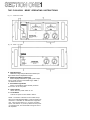
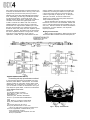
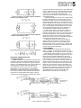
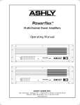
THE P-2200/2201 BRIEF OPERATING INSTRUCTIONS
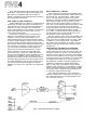
Fig. 1A - P-2200 Front Panel
Fig. 1B - P2201 Front Panel
A. Input Attenuators
Calibrated, stepped input attenuators lower input
signal levels ahead of amplification stages.
B. Peak Reading Meters (P-2200 only)
Meters display instantaneous (peak) power output
into an 8-ohm load over a full 50dB range; "0dB" =
100 Watts into 8 ohms.
C. Thermal Warning Indicator
Warns of overheating before thermal protection
circuit turns off the AC power.
D. Power Indicator
Glows when the power switch is "on."
E. On-Off Switch
Controls AC power to the P-2200 or P2201.
NOTE: The P2201 is identical to the P-2200 except
there are no Peak Reading Meters. Both are made to be
mounted in a standard 19" wide electronic equipment
rack. Each of them takes up 7" (17.6cm) of vertical
space, and extends 13" (33.0cm ) behind its front panel.
For portable racks, we recommend bracing the rear of
the amplifiers.
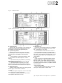
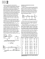
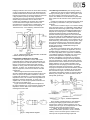
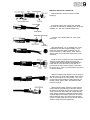
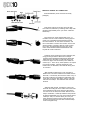
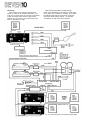
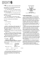
Fig. 2A - P-2200 Rear Panel*
Fig. 2B - P2201 Rear Panel*
A. Input Connectors
The two XLR input connectors on each channel are
unbalanced and are wired in parallel with each other
and with the two phone jacks (tip/sleeve type).
B. Input Polarity Switch
Determines the polarity of the two XLR input
connectors (Pin 2 or Pin 3 "hot"); does not affect the
two phone jacks. See diagram on the rear panel.
NOTES:
1. Input impedance is 25k-ohms minimum; +4dB
(1.23V) produces 230 watts output into 8 ohms
(44.7V).
2. Input channels may be parallelled by connecting
them together with phone to phone or XLR to XLR
cables as shown on Page SIX 7.
3. Input transformers for matching or isolation,
should be located several inches from the P-2200 or
P2201's power transformer for maximum hum rejection.
C. Output Connectors
Standard 5-way binding posts (3/4" spacing) accept
banana plugs or direct-wired connections.
D. AC Power Cord
For the U.S. and Canadian models, the P-2200/2201
require 117 VAC 50 or 60 Hz line ( 1 0 5 V min., 1 3 5 V
max.; 8 amps max. at 120 volts).
For the Australian model: 240V AC 50 or 60 Hz.
For other territories' models, an internal voltage
selector (220 V/240 V switchable) is provided near the
rear panel. In this case 220 V is factory-preset. If you
want to change into 240 V line, consult your nearest
Yamaha dealer.
E. Fuses
7 amp, 125 volt (x 2), type AGC (3AG); U.S. and
Canadian models only. 4 amp, 250 volt (x 2); other
territories models. Fuses should always be replaced
with same size and type. If the fuses blow consistently,
the amplifier should be checked by a qualified Yamaha
service technician.
F. AC Accessory Outlets
These convenience outlets are made for low power
cooling fans. Not provided in certain areas.
NOTES:
1. Maximum power output into 8 ohms is 230 watts;
power output rises at lower impedances.
2. Protection circuitry towers power output when
load impedance falls below 2.5 ohms.
The rear panels shown here are subject to U.S. specifications.
INTRODUCTION
The P-2200 is not just "another big amplifier;" it is
an exciting new approach to high power sound. Yamaha's
leadership is clearly demonstrated by the P-2200's professional features, sophisticated design, and uncompromising performance.
PEAK READING METERS*
Instead of the more common and slow responding
VU meters, the P-2200 has PEAK READING METERS
that accurately display a full five decades (50dB) of
output level. The peak meters have large, illuminated
faces marked with dB and with watts into 8 ohms. The
fast responding meters provide a better way to see the
program dynamics, the transient power demands placed
on the system, and the available headroom. By indicating
headroom, the meters help the operator avoid overdriving the system, thereby preventing the "clipped"
waveforms so dangerous to drivers and loudspeakers.
CALIBRATED INPUT ATTENUATORS
The P-2200 has log-linear INPUT ATTENUATORS to
complement its peak reading meters. The input attenuators are marked in 22dB-calibrated steps, detented for
extra accuracy. The attenuators provide a smooth, noise
free transition from the highest to the lowest audio level.
dB-calibrated input attenuators have numerous
advantages: on the road, they allow predictable and
repeatable setups; in commercial sound applications,
they allow easy, accurate input sensitivity adjustments;
in studios or discos, they let operators simultaneously
adjust the level of two channels (or two programs on
separate amplifiers) with precise tracking.
INPUT AND OUTPUT CONNECTIONS
INPUT CONNECTORS for each channel include one
"male" and one "female" XLR connector (unbalanced)
plus two parallel phone jacks. This provides the flexibility necessary for convenient bridging to another
amplifier, as well as for adapter-free connection to
almost any mixer. A POLARITY switch allows either
pin 2 or pin 3 of the XLR to be chosen as the "hot"
lead, satisfying DIN/JIS or USA standards. Outputs are
standard five way binding posts, usable with high current
"banana" plugs or direct wired connections.
MONAURAL OPERATION
The P-2200 may be converted to a monaural "super
amplifier" by inserting two matched transformers
ahead of the inputs, feeding the same signal to both,
and reversing the POLARITY switch on one input. This
creates a transformerless balanced output, the speaker
load "bridged" across the "hot" terminals of both
channels. In this mode, the P-2200 is suitable for
driving almost any load, including highly reactive 70-volt
commercial speaker lines. With a full 400 watts into
1 6 ohms, the P-2200 in mono mode eliminates the need
for several smaller 70-volt amplifiers.
PERFORMANCE
The P-2200's performance is as impressive as its
features. At a sustained output of 230 watts into 8 ohms
(for each channel), there is plenty of punch to reproduce
the powerful peaks essential to clean studio monitoring.
High power handling also makes the P-2200 an unbeatable choice for live rock or disco sound systems, where
an amplifier can really "cook" all night long. Power alone
is no virtue; the P-2200 has ultra-low distortion, less than
0.05% THD at full rated power - the kind of low
distortion that is undetectable by even the most critical
listeners.
A high damping factor of better than 300 at
frequencies below 1kHz reduces the tendency for
speaker cone overshoot, giving tighter and better defined
bass response. On the other end, the P-2200's frequency
response extends well beyond 100kHz, enabling it to
accurately reproduce the most complex musical waveforms — even the tortuous output of today's synthesizers. However, high frequency response has not been
achieved at the expense of stability; in fact, the P-2200
is rock steady. Even when connected to highly reactive
multi-speaker loads, there is no tendency to shut down
or "take off" into spurious oscillation.
MECHANICAL CONSIDERATIONS
The P-2200 is constructed to withstand the high "G"
forces encountered on the road. Its solid front panel
mounts in any standard 19-inch rack, and, for a large
amplifier, the P-2200 weighs a modest 44 pounds
(20kg)** Front panel controls and meters are recessed to
avoid damage or accidental setting changes, and are
further protected by a pair of sturdy carrying handles.
Inside and out, the P-2200 is extremely reliable. Still,
should service ever be required, the unit is designed for
easy access. Massive side-mounted heat sinks are
designed for efficient cooling, making fans unnecessary
in all but the most severe thermal operating conditions.
Four non-conductive feet ensure proper air flow when
the amplifier is shelf mounted, and avoid inadvertent
ground loops. Multiple protection circuits make the
amplifier nearly abuse proof and eliminate the need for
troublesome DC power supply fuses.
* The P2201 does not have the Peak Reading Meters.
* * The P2201 weighs 42 pounds (19kg)
GENERAL SPECIFICATIONS
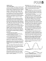
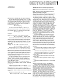
Phase Shift: (Refer to Figure 1 1 . )
20Hz to 20kHz, ± 1 0 degrees.
Offset Voltage:
Less than ±10mV DC.
Unit Step Function Response: (Refer to Figure 27.)
See scope photo (Page FOUR 4) and discussion,
Page FOUR 6.
Power Output Per Channel: (Refer to Figure 3. Ambient
room temperature for tests: 25-degrees Centigrade.)
200 Watts continuous average sine wave power into
8 ohms with less than 0.05% THD, (Total Harmonic
Distortion), over a bandwidth of 20Hz to 20kHz,
both channels driven.
230 Watts continuous average sine wave power into
8 ohms with less than 0.05% THD, at 1 kHz, both
channels driven.
Frequency Response: (Refer to Figure 5.)
+0dB, -0.5dB, 20Hz to 50kHz.
Total Harmonic Distortion: (Refer to Figure 6.)
Less than 0.005% @ 50 Watts, 8 ohms, 1kHz.
Less than 0.01% @ 150 Watts, 8 ohms, 20Hz to
20kHz.
Intermodulation Distortion: (Refer to Figure 7.)
Less than 0.01% using frequencies of 70Hz and
7kHz, mixed in a ratio of 4:1, single channel power
output of 150 Watts into 8 ohms.
Input Sensitivity:
An input of +4dB* (1.23V), ±0.5dB, produces an
output of 230 Watts into 8 ohms (maximum output
power), INPUT attenuator set for maximum level.
Input Impedance:
25k-ohms, minimum (unbalanced).
Damping Factor: (@ 8 ohms / (Refer to Figure 8.)
Greater than 300 at any frequency from 20Hz to
1kHz; greater than 70 at any frequency from 20Hz
to 20kHz.
Actual Output Impedance: (Refer to Figure 9.)
Less than 0.04 ohms, from 20Hz to 10kHz.
Hum and Noise:
At least 110dB signal-to-noise ratio (l.H.F./A.S.A.
No. Z24.3-1944).
Rise Time:
3.8 microseconds, or better (10%-90% of 1 volt @
1kHz square wave output).
Slew Rate:
45 volts per microsecond, or better (at 175 Watts into
8 ohms, 200kHz square-wave input).
Channel Separation: (Refer to Figure 10.)
At least 82dB at 1kHz, at least 75dB at 20kHz.
*In these specifications, when dB represents a specific voltage,
0dB is referenced to 0.775V. "dB" is a voltage level, whereas
"dBm" is a power level. 0dBm is referenced to 1mW (0.775V
driving a 600-ohm termination). For example, when 12.3V is
fed to a high impedance, the level is designated "+24dB." When
+24dB (12.3 volts) drives a 600-ohm termination, the level is
designated "+24dBm." The level in "dB" is specified, wherever
applicable, to avoid confusion when the input is fed by various
low and high impedance sources. See the APPENDIX beginning
on Page EIGHT 1 for a further discussion of dB.
Thermal Specifications:
Massive black anodized heat sinks are thermally
joined with the chassis, thereby utilizing the entire
amplifier as a heat sink.
Protection Circuits:
Thermal warning light turns on when heat sink
temperature reaches 100-degrees Centigrade.
A self-resetting thermal switch shuts down the AC
power if the power transformer winding temperature
reaches 130-degrees Centigrade. See Page SIX 13 for
power overload circuit specs.
Turn On/Turn Off Specs:
There is no turn off transient; the turn on transient
is minimal (see Page SIX 13). Warm up time is less
than 0.2 seconds.
Power Requirements:
For the U.S. and Canadian models: AC, 120 Volts
nominal, 50-60Hz (105V min., 135V max.); 8
amperes maximum at 120V AC; 960 volt-amperes
maximum at 120 Volts; approximately 57 voltamperes at idle.
For other territories models: 1,300 Watts, 220 or 240
Volts AC nominal, 50-60Hz.
Efficiency: (Refer to Figure 12.)
As high as 63%; see Page FOUR 2.
NOTE: All performance specifications are made on U.S.
and Canadian models at an AC line voltage of 120 Volts
±1%, using a ±1% nonreactive load resistor at an
ambient room temperature of 25-degrees Centigrade.
Also effective for other territories' models.
Input Connectors:
One "male" and one "female" XLR connector in
parallel, pin 2 "hot," pin 3 connected to pin 1
(shield); switchable for pin 3 "hot." XLR's are unbalanced and in parallel with two tip-sleeve
(standard) phone jacks.
Output Connectors:
Standard 3/4-inch spacing, "5-way" binding posts.
Meters and Indicators:
Two peak reading meters (one per channel) indicate
the instantaneous power output, over a 5-decade
(50dB) range. "0dB" represents 100 Watts into
8 ohms. (P-2200 only)
One "power ON" indicator LED; one "Thermal
Overload" indicator LED.
Meter Rise Time (P-2200 only):
Less than 10 milliseconds; (-40dB to 0dB
on the scale).
Meter Release Time (P-2200 only):
Less than 0.8 seconds; (0dB to -20dB on the
meter scale).
Meter Accuracy (P-2200 only):
See graph, Figure 13, Page FOUR 2.
Controls:
22-position, log-linear, detented, and dB-calibrated
INPUT ATTENUATORS (one per channel)
attenuate input signal in 2dB steps from 0dB
attenuation to -34dB, then steps of -37dB, -42dB,
-50dB, infinity; Power (ON-OFF) switch; INPUT
POLARITY switches.
MONAURAL MODE SPECIFICATIONS
Fuses:
AGC (3AG) type, 7-amps x 2 parallel fuses for the
AC line input (U.S. and Canadian models).
4-amps x 2 parallel fuses for the AC line input
(other territories' models).
Dimensions:
Mounts in a standard 19-inch (48cm) rack. 7" high
(17.6cm); maximum depth behind front panel is
13" (33.0cm); maximum depth including front
handles 14-1/2" (37.9cm).
Total Harmonic Distortion: (Refer to Figures 17 and 18.)
Less than 0.01% @ 300 Watts into 1 6 ohms at 1kHz.
Weight:
P-2200; 44 pounds (20kg), P2201; 42 pounds (19kg).
Color:
Semi-gloss black.
Input Impedance:
25K-ohms minimum (unbalanced).
Power Output: (Refer to Figures 14 and 15.)
400 Watts continuous average sine wave power into
16 ohms with less than 0.05% THD, 20Hz to 20kHz.
Frequency Response: (Refer to Figure 16)
+0dB, -1dB, 20Hz to 50kHz.
Intermodulation Distortion:
Less than 0.05% using frequencies of 70Hz and 7kHz,
mixed in a ratio of 4:1, at a power output of 200
Watts into 1 6 ohms.
Input Sensitivity:
An input of 0dB (0.775 Volts), ±0.5dB, produces an
output of 200 Watts into 16 ohms (INPUT attenuator
set for minimum attenuation, maximum level).
Damping Factor: (@ 16 ohms) (Refer to Figures 19
and20).
Greater than 220 at any frequency from 20Hz to
1kHz; greater than 100 at any frequency from 20Hz
to 20kHz.
Hum and Noise:
At least 110dB signal-to-noise ratio (I.H.F./A.S.A.
No. Z24.3-1944).
Slew Rate:
35 volts per microsecond, or better, at 100 Watts into
1 6 ohms, 200kHz square wave input.
Specifications subject to change without notice.
PERFORMANCE GRAPHS &
A DISCUSSION OF SPECIFICATIONS
NOTE: In the discussion beginning on Page FOUR 5,
references to specific specifications assume normal stereo
operation (not mono operation) unless otherwise indicated.
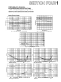
Normal (Stereo) Graphs
Fig. 3 - Power Bandwidth vs Load Impedance
Fig. 4 - Load Impedance vs Output Power
Fig. 5 - Frequency Response vs Load
Fig. 6A - T.H.D. vs Output Power at 8
(both channels driven)
Load Impedance
Fig. 7 - Intermodulation Distortion vs Power Output at
8 and 16 Load Impedance
Fig. 6B - T.H.D. vs Output Power at 16 Load Impedance
(both channels driven)
Fig. 8 - Damping Factor vs Frequency at 8
Impedance
Load
Fig. 9 - Actual Output Impedance vs Frequency
Fig. 1 1 - Phase Response vs Frequency
Fig. 10 - Crosstalk (Channel Separation)
Fig. 1 2 - Power Consumption
Fig. 1 3 - Peak Program Meter Accuracy (P-2200 only)
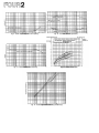
Mono Mode Graphs
Fig. 14 - Power Bandwidth vs Frequency (Mono Mode)
at 16 Load Impedance
Fig. 16 - Frequency Response (Mono Mode) at 16
Impedance
Load
Fig. 1 8 - T.H.D. vs Frequency (Mono Mode) at 16
Impedance
Load
Fig. 15 - Load Impedance vs Output Power (Mono Mode)
at 0.1% T.H.D., 1kHz
Fig. 1 7 - T.H.D. vs Power Output (Mono Mode) at 16
Load Impedance
16
Fig. 19 - Damping Factor vs Frequency (Mono Mode) at
Load Impedance
Fig. 20 - Actual Output Impedance (Mono Mode) vs
Frequency
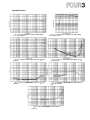
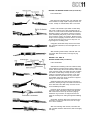
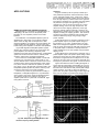
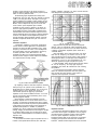
The following are actual oscilloscope photographs
made by an independent testing laboratory. The close
vertical alignment of input and output traces in Fig. 21
through 23 depicts very low phase shift, so the amplifier
will not alter musical wave shapes.
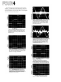
Fig. 24 - 1,000Hz Sine Wave, shown with HighlyMagnified Noise and Distortion Components
Even at full 230 watt output (8-ohms), the
P-2200's distortion is so low that it is almost
burried in the noise, which is at least 110dB
below the sine wave output. The sine wave is
clean and symmetrical.
Fig. 21 - 10Hz Square-Wave Response
The output waveform displays very respectable
low frequency response. The slight "tilt" shows
a DC gain of unity, which prevents damage to
speakers in the event any DC offset is fed to the
amplifier input.
Fig. 25-20,000Hz Sine Wave, shown with HighlyMagnified Noise and Distortion Components
While no amplifier should ever have to produce 230 watts continuous output at 20kHz,
the P-2200 does it with low distortion, and
symmetrical reproduction. As In Fig. 1 1 , the
noise (magnified here) is actually better than
110dB below the sine wave.
Fig. 22 - 1,000Hz Square-Wave Response
Near-perfect response is evident in the duplication of the input waveform by the output waveform. There are no "squiggles" or spikes, meaning there Is no ringing or overshoot.
Fig. 26 - Square-Wave Response into a HighlyInductive Load (at 1kHz)
The ability of the P-2200 to maintain a
sharply defined square wave output into a
reactive load demonstrates stability under the
worst conditions. There is still a complete lack
of unwanted ringing, as well as low phase shift.
Fig. 23 - 20,000Hz Square-Wave Response
The extremely fast and symmetrical rise and
fall times of the amplifier are evident, demonstrating the ability to accurately reproduce
musical waveforms and harmonics well beyond
the range of human hearing.
Fig. 27 - Unit-step Function Response
POWER OUTPUT
Types of Power Ratings
Peak power refers to the maximum undistorted power
output of an amplifier. Most amplifiers cannot sustain
their peak power ratings for long periods of time without
external cooling fans. Because there are many different
methods of rating an amplifier's peak power, it is hard to
objectively compare the peak power ratings of two
amplifiers. The peak power rating is primarily useful
for determining an amplifier's ability to reproduce the
peaks and transients in a musical program, peaks which
may be 20dB or more above the average power level.
The ability to accurately reproduce these high power
peaks in a musical program is one of the most important
advantages of the P-2200 as compared to a smaller
power amplifier.
"RMS"power is actually a misnomer for average
power. Average power is usually measured with a sine
wave input signal, and is equal to the amplifier's RMS
output voltage squared and then divided by the load
impedance (see Appendix). Because RMS voltage is used
in the formula, the resulting power rating is commonly
called "RMS power." While it means the same as "RMS
power," to be more accurate, the P-2200 is rated in watts
of "continuous average sine wave power."
Since the P-2200 is a professional power amplifier,
not sold for home hi-fi use, it is not required to meet the
power rating standard set by the FTC (Federal Trade
Commission), a standard meant for consumer power
amplifiers. However, the P-2200 is measured under
severe conditions which simulate the most demanding
professional usage. Thus, the P-2200 would easily meet
the FTC ratings for consumer amplifiers. In addition,
the P-2200 user has the benefits of professional features
and reliability.
Reasons for a High Power Amplifier
An interesting characteristic of the human ear is
described by the "Weber-Fechner" law. In its general
form, the law applies to all our senses:
The amount of additional stimulus needed to
produce a perceptible change is dependent on the
amount of stimulus already present.
In mathematical terms, the Weber-Fechner law
suggests that the human ear responds to changes in
sound level in a logarithmic manner. More simply this
means that for a sound to seem twice as loud, it requires
approximately ten times as much acoustic power (and
therefore ten times as much amplifier power). Thus, the
P-2200's high power output capabilities are extremely
valuable.
One of the other benefits of high power output is the
ability of the amplifier to easily reproduce high peak
power transients (which may be 100 times the average
program power, or even more). This subject is discussed
further on Pages FIVE 2 and FIVE 4.
DISTORTION (Refer to Figures 6A-B, 7, 17, 18)
The P-2200 is designed to have the lowest possible
distortion. There are many different forms of distortion,
however, and comprehensive distortion ratings offer a
means to compare the performance of different
amplifiers.
Harmonic Distortion, is characterized by the appearance at the amplifier output of harmonics of the input
waveform which were not present in the original input
waveform. Total Harmonic Distortion, or T.H.D. is the
sum total of all of these unwanted harmonics expressed
as a percentage of the total signal.
Harmonic distortion, in an amplifier, can be created
in any of several ways. The T.H.D. rating of a power
amplifier refers to creation of unwanted harmonics by
the amplifier during "linear" operation (normal input
and output levels, impedances, etc.). Harmonic distortion
is also created by "clipping," a form of "non-linear"
operation, which occurs when the signal level at an
amplifier's input is high enough to drive the amplifier
beyond its rated maximum output. The amplifier, in
attempting to reproduce this signal, reaches its maximum
output voltage swing before it reproduces the top of the
signal waveforms. Since the output voltage cannot rise
any farther, the tops of the waveform are "squared off,"
or clipped, as that shown in Figure 65. Clipping distortion adds odd upper harmonics (3rd harmonic,
5th, etc.) to the original signal. (Input clipping would
be similar, where the input stage of the amplifier is
overdriven by a high level input signal.) The P-2200 has
wide input headroom and extremely high peak power
output capabilities (headroom) to help avoid the problems of clipping distortion.
Another form of harmonic distortion that occurs in
some power amplifiers is called crossover distortion. *
Crossover distortion can be caused by improper bias in the
output transistors of an amplifier. The amount of crossover distortion stays the same whether the signal is large
or small, so the percentage of distortion goes down as
the signal level goes up. Thus, an amplifier with crossover
distortion may sound relatively distortion free at high
output levels, yet sound "fuzzy" at low levels. Some
amplifiers have internal adjustments which enable a
service technician to control the amount of output
transistor bias, and therefore control the distortion. The
P-2200 has automatic biasing circuitry which needs no
adjustment and avoids crossover distortion under all
operating conditions.
Power Output versus Load
Within its maximum limits, the P-2200 acts like a
perfect voltage source (see Appendix), that is, its power
output rises with decreasing load impedance. When the
load impedance drops below 2.5 ohms, the P-2200's
protection circuits begin to limit the power, resulting
in the curve shown in Figure 4 (normal operation) and
Figure 1 5 (mono operation).
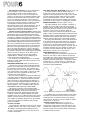
Fig. 28A - Large Amplitude Sine Wave with Crossover
(notch) Distortion.
Fig. 28B - Smaller Amplitude Sine Wave with same amount
(higher %) of Crossover (notch) Distortion.
"Crossover," in this case. refers to the transition between the
positive half and the negative half of the output voltage wave-
form in a "push-pull" class B or AB power amplifier: it has
nothing to do with the crossover used to divide frequencies in
a speaker system. See Figure 28.
Intermodulation Distortion, or I.M. is characterized
by the appearance in the output waveform of frequencies that are equal to sums and differences of
integral multiples of two or more of the frequencies
present in the input signal. The difference between intermodulation distortion and harmonic distortion is that
two or more different frequencies must be present to
produce intermodulation distortion (only one frequency
is needed for harmonic distortion to appear), and that
intermodulation distortion products may not be
harmonically related to the original frequencies. Like its
harmonic distortion figure, the intermodulation distortion in the P-2200 is low enough to be virtually
inaudible even in the most critical situations.
Dynamic Frequency Response Shift is related to both
harmonic and intermodulation distortion. When high-level
low and high frequency signals are present in the same
waveform, the high frequency signals "ride" on top of the
low frequency waveforms (see Figure 65, Page SEVEN 1 ) .
If amplifier headroom is inadequate, the low frequencies
may "push" the high frequencies above the output limits
of the amplifier, clipping them off the waveform (Figure
65C). The low frequencies may remain unaltered, but the
high frequencies are severely reduced. At the same time,
harmonics of the high frequencies are produced which
add to the super high frequency content of the signal.
Thus, along with the distortion created by the clipping,
the frequency response of the original signal is drastically
altered. This type of distortion can be reduced by increasing system headroom (using a more powerful
amplifier like the P-2200), and by biamplifying the
system as discussed on Page SEVEN 1 .
The extremely low distortion figures of the P-2200
indicate its overall quality and mean that its sound will
be precise and natural.
FREQUENCY RESPONSE (Refer to Figures 5 & 16)
The frequency response of the P-2200 describes the
variation in its output signal level with frequency when
the input signal is held constant. The extremely "flat"
frequency response curve of the P-2200 is an indication
of its overall quality and its ability to respond to upper
and lower harmonics of signals all the way to the
extremes of the audio spectrum.
Because extreme stability is necessary for some types
of commercial sound applications, notably 70-volt lines
(see Page SEVEN 1 1 ) , some manufacturers restrict frequency response or allow relatively high distortion in
return for increased amplifier stability. The P-2200, on
the other hand, has excellent frequency response and
ultra-low distortion, yet is inherently stable under the
UNIT STEP FUNCTION RESPONSE (Refer to Figure 27)
A unit step function is like the leading edge of a
square wave; it goes up, but never comes down. The
response to this input indicates the output of the P-2200
for a DC input signal which might come from a faulty
direct coupled preamplifier or mixer. Note that the
P-2200 will not reproduce a DC voltage fed to its input,
thus adding an extra measure of loudspeaker protection.
POWER BANDWIDTH (Refer to Figures 3 & 14)
The power bandwidth of the P-2200 is a measure of
its ability to produce high power output over a wide
frequency range. The limits of the power bandwidth are
those points where the P-2200 can only produce 1/2 the
power that it can produce at 1000Hz. While the
frequency response is measured at relatively low power
output (1 watt), the power bandwidth is measured at the
P-2200's full power output (before clipping). The power
bandwidth of the P-2200 is quite "flat," and extends to
200kHz, well beyond the limits of the audio spectrum.
The wide power bandwidth of the P-2200 means that
it can reproduce high level upper harmonics of a signal
as easily as it can reproduce mid-range fundamentals. It
means that you get full power performance from the
P-2200 over the entire audio frequency spectrum. This is
especially important when the amplifier is called upon
to reproduce musical material with high energy over a
wide frequency range, such as rock and roll.
PHASE RESPONSE (Refer to Figure 11)
The phase response of the P-2200 is a measure of the
amount of time delay it adds to different frequencies.
An amplifier with perfect phase response would introduce
equal time delay at all frequencies reproduced. The
P-2200's worst case phase shift of -10 degrees at 20kHz
corresponds to a 1.4 microsecond (1.4 millionths of a
second) delay period which is insignificant in even the
most critical audio applications.
most difficult loads, even in the "mono" mode.
The frequency response of the P-2200 has been
intentionally limited, however, at very low frequencies
(sub-audio). Because of this, severe low frequency
transients, or DC offset, appearing at the input to the
P-2200 are unlikely to damage a speaker load. Other
amplifiers which are DC coupled throughout may have a
"flatter" sub-audio frequency response, but this makes
them capable of amplifying dangerous DC input voltage
or sub-audio transients and delivering them (at high
power) to a speaker.
OFFSET VOLTAGE
This specification indicates the amount of DC voltage
naturally present at the output of the amplifier. A high
DC voltage could damage the loudspeaker load; the
±10mV ( 1 0 one-thousandths of a volt) level from the
P-2200 is insignificant.
Fig. 29 - Waveform of Amplifier with Poor Phase Response.
An amplifier with poor phase response would change
the shape of a waveform that was made up of a fundamental frequency and several harmonics by delaying
each harmonic differently. The effect might be similar
to that shown in Figure 29.
CHANNEL SEPARATION (Refer to Figure 10)
This specification indicates the output from one
channel when a signal is fed to the other channel. The
P-2200's channel separation is very good, which means
that even critical stereo programs will be unaffected by
crosstalk between channels.
HUM AND NOISE
Hum or noise from a power amplifier disrupts a
program, and is irritating to a listener. Hum and noise
could be considered a form of distortion. The P-2200's
hum and noise are so low that they are completely
inaudible under any normal listening circumstances.
RISE TIME
Rise time is a measurement of the amount of time an
amplifier requires to respond to a square wave at a
specified frequency. The rise time of an amplifier is an
indication of its frequency response. A fast rise time
corresponds to a wide frequency response. The P-2200's
rise time specification is measured with a 1000Hz square
wave output signal of one volt peak-to-peak amplitude.
The rise time is the time the amplifier requires to change
from 10% (0.1 volt) to 90% (0.9 volt) of its output. To
improve measurement accuracy, the first and last 10%
are normally not included in the test (any slight nonlinearities that occur in the test signal or the amplifier
could lead to measurement error).
SLEW RATE
Slew rate is a measure of a power amplifier's ability
to follow a fast rising waveform at higher frequencies
and higher power outputs than the rise time measurement. The P-2200's slew rate is measured with a 200kHz
square wave input signal, at 175 Watts output power
into 8 ohms.
It might seem reasonable to assume that the fastest
slew rate for an audio waveform occurs at 20kHz.
However, this is not the case. When one frequency is
superimposed upon another, the combined waveform
has a slew rate that is greater than the slew rate of
either signal by itself. The actual value of the slew rate
of one of these waveforms (or any waveform) depends
not only on the frequency, but on the amplitude of the
waveform as well. Thus, the criteria for a good slew rate
specification, which indicates that an amplifier can
reproduce these combination waveforms, varies with
the maximum power output capability of the amplifier.
The higher the power, the higher the required slew rate.
With a 45 volts/microsecond slew rate, the P-2200 can
easily reproduce even the most extreme audio waveforms at its full power output.
INPUT IMPEDANCE
The input impedance of the P-2200 is high enough
to allow it to be used with most semi-pro devices, or to
be used as a "bridging" load for a 600-ohm source.
Page SIX 2 details input impedance and level matching
for the P-2200.
INPUT SENSITIVITY
The P-2200's input sensitivity indicates the input
drive voltage needed for the P-2200 to produce its
rated output of 230 watts into 8 ohms (input attenuators are adjusted to maximum clockwise rotation for
minimum attenuation).
PROTECTION CIRCUITS AND
THERMAL SPECIFICATIONS
See the discussions under INSTALLATION, on
Page SIX 13.
GAIN
Gain is the ratio of the P-2200's output voltage to its
input voltage. Maximum gain occurs when the input
attenuators are set for minimum attenuation. If the input
and output voltage are specified in dB, the voltage gain is
equal to the difference of the two dB numbers. As stated
under INPUT SENSITIVITY, an input voltage of +4dB
(1.23 volts) produces an output power of 230 watts into
an 8-ohm load. 230 watts into 8 ohms implies an
output voltage of 43 volts which corresponds to +35dB
(referenced to 0.775 volts, as used in this manual). The
voltage gain of the P-2200, with its input attenuators set
for minimum attenuation, then, is 31dB [(+35dB)-(+4dB)].
OUTPUT IMPEDANCE (Refer to Figures 9 & 20)
The output impedance of the P-2200 is extremely
low. Thus, within its operating limits, the P-2200 is a
good approximation of a perfect voltage source and will
deliver increasing power levels into lower impedance
loads in a linear fashion according to Ohm's law. The
Appendix discusses Ohm's law and the concept of a
perfect voltage source.
DAMPING FACTOR
Damping factor is a term that is derived by
dividing the load impedance (speaker or other load) by
the amplifier's output impedance. Thus, a high damping
factor indicates a low output impedance at a specified
load.
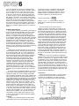
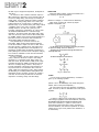
The cone/voice-coil assembly of a loudspeaker gains
inertia during its back and forth movements. This
inertia can cause it to "overshoot," that is, to continue
movement in one direction, even when the amplifier
is trying to pull it back in the other direction. An
amplifier with a low output impedance can "damp"
(reduce) unwanted loudspeaker motions, as explained
below.
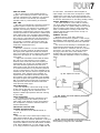
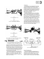
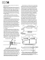
Fig. 30A - Speaker Cone at Rest
Fig. 30B - Speaker Cone moved outward by Postive-Going
Voltage from Amplifier.
Fig. 30C - Voltage from Amplifier has dropped to Zero but
Speaker Cone has moved back PAST its rest position (overshoot)
and is producing a voltage of its own: "Back EMF"
During the "overshoot" movement, the voice coil of
the loudspeaker interacts with the loudspeaker's magnetic
assembly to produce a voltage called "back E.M.F."
(electro-motive force). This action is similar to the
operation of a dynamic microphone. If the amplifier's
output impedance is low, this "back E.M.F." voltage is
shunted through the amplifier's output circuits to
ground, and back to the voice coil. Since the path from
the voice coil, through the amplifier's output circuits,
and back to the voice coil is a complete circuit, a
current flows in the voice coil. This current, causes
the voice coil to act like an electro-magnet; the electromagnet (voice coil) interacts with the magnetic assembly
of the loudspeaker, and the unwanted overshoot is
reduced (a magnetic braking action).
Fig. 31 - Current produced by "Back EMF" follows path
through Amplifier's Output Impedance to speaker-coil.
If the amplifier's output impedance is low (considerably less than the impedance of the loudspeaker
voice coil), this damping action is limited only by the
resistance of the voice coil combined with the resistance
of the speaker lead wires. While the value of a high
damping factor in reducing cone overshoot is disputed,
the P-2200's high damping factor is evidence of good
overall engineering design.
THE DISTINCTION BETWEEN
PROFESSIONAL AND HI-FI
EQUIPMENT
In most applications, a variety of auxiliary equipment
will be connected to the P-2200, including: mixers, tape
machines, compressors, graphic equalizers, echo, time
delay, and reverb units, and just about any other audio
electronics imaginable. Regardless of the function of
auxiliary equipment, it will undoubtedly fall into one of
two general categories, professional type or hi-fi type.
The following criteria place most "semi-pro" equipment
in the hi-fi classification.
The distinction between professional and hi-fi equipment is important primarily because it affects the way it
will be used with the P-2200. Brand name, size, panel
colors, durability and subtleties in function are not the
significant differences. What matters is that professional
equipment and hi-fi equipment usually operate at
different input and output levels, and require different
source and load impedances to function properly. The
P-2200 is designed to function well with other professional equipment, although it has high enough input
impedance and sensitivity to yield excellent results with
hi-fi type equipment if a few precautions are observed.
(These precautions are outlined in the Installation section of the manual.) The following paragraphs explain
how the specific requirements differ for professional and
hi-fi (or semi-pro) equipment.
IMPEDANCE
The inputs of a piece of professional audio equipment
are usually designed to be driven from a low impedance
source, nominally 150 to 600 ohms, and its outputs will
drive low impedance (600 ohm or higher) loads. (Power
amplifier outputs are not considered in this discussion.)
Professional input and output circuits may be
unbalanced, but they are often transformer isolated
(balanced or floating), and use dual conductor shielded
cables, with 3-pin XLR type connectors or Tip/Ring/
Sleeve phone plugs.
The P-2200's inputs are unbalanced due to cost and
adaptability factors. To internally balance the inputs of
the P-2200 would require two matched input transformers with heavy shielding (to avoid hum pickup from
the P-2200's power transformer). Induced hum in low
level circuits, especially in low level transformers, can
be a problem with any power amplifier, or other high
current device (such as a DC power supply). High quality
external transformers with less shielding can achieve the
same results with a substantial cost savings. In addition,
the user can choose the optimum impedance ratio for
a given situation, increasing the P-2200's adaptability.
Either the "matching transformer box" or "step up
transformer box" described on Pages SIX 3, and SIX 4
are suitable, so long as they are kept several inches
away from the P-2200.
Hi-fi (and semi-pro) equipment generally is designed
to be driven from a 5,000-ohm (or lower impedance)
source, and its output will drive 10,000-ohm (or higher
impedance) loads. Hi-fi input and output circuits are
usually unbalanced, and use single conductor shielded
cables with 2-conductor connectors, either standard
phone plugs or phono plugs (also called RCA or pin
plugs). Occasionally, the inputs of a piece of hi-fi or
semi-pro equipment are professional XLR connectors
which have been converted to a 2-wire, unbalanced
circuit by internally connecting either pin 2 or pin 3
to pin 1.
The nature of unbalanced, balanced, and floating
circuitry is discussed further in the Appendix of this
manual. For the purpose of this discussion, the most
significant point is that an unbalanced circuit is somewhat more susceptible to hum and noise, especially if
there is any irregularity in the grounding system.
NOTE: THERE IS NO CORRELATION BETWEEN
"BALANCED" OR "FLOATING" AND CIRCUIT
IMPEDANCE.
Low impedance and high impedance are relative
terms. A 150- to 250-ohm microphone is considered low
impedance, whereas a 10,000-ohm mic is considered
high impedance. A 600-ohm line is considered low
impedance, whereas 10,000-ohm, 50,000-ohm or
250,000-ohm lines are all considered high impedance.
Sometimes, mics and lines with an impedance of 600
ohms to about 2000 ohms are considered "medium"
impedance. NOTE: THE IMPEDANCE OF A CIRCUIT
SAYS NOTHING ABOUT ITS LEVEL.
While the exact transition between low and high
impedance is not clearly defined, the distinction is still
important, primarily because the output impedance of a
source determines the length of cable that can be
connected between it and a load before a serious loss
of high frequencies occurs. The losses occur because all
cables, and especially shielded cables, have some
capacitance between their conductors. Some guitar
coil cords may measure as high as 1000 picofarads total
capacitance! A source impedance (such as a high
impedance mixer output) and the capacitance of a
cable form a type of low-pass filter a filter that attenuates high frequencies. This filtering effect, can be
reduced by using low capacitance cable, by shortening
the length of the cable, by using a low impedance source
or by some combination of these methods.
Fig. 32 - The Source's Output Impedance and the Cable
Capacitance act as an "RC Lowpass" Filter which Attenuates
High Frequencies.
Cables from high impedance sources (5000 ohms and
up), should not be any longer than 25', even if low
capacitance cable is used; shorten the cables if the
impedance is higher. For low impedance sources of 600
ohms or less, cable lengths to 100' are relatively effective.
For very low impedance sources of 50-ohms or less,
cable lengths of up to 1000 feet are possible with
minimal loss. However, the frequency response of the
source, the desired frequency response of the system,
and the amount of capacitance and resistance in the
cable all play a role in any potential high frequency
losses. Thus, these values are meant as guide lines, and
should not be considered fixed rules.
For short runs and in smaller systems with fewer
components, the performance of an unbalanced circuit
may be adequate. In a long cable run, a balanced or
floating circuit tends to reject hum and noise pickup
better than an unbalanced circuit, and in complex
systems, with several components separated by some
distance and running on different AC outlets, balanced
or floating circuits make proper grounding much easier.
In any given situation, the decision to use a hi-fi
(semi-pro) device or a professional one should be based
on the specifications of the inputs and outputs of that
device and on the requirements of the application.
OPERATING LEVELS
Nominal professional line level is usually +4dBm or
+8dBm; that is, the average program level is approximately 1.23V rms (+4dBm), or 1.95V rms (+8dBm)
terminated by a 600-ohm line. The peak level may
extend to about +24dBm (12.3V rms). The line (high
level) input of professional audio equipment is
designed to accept levels on this order of magnitude
without overdrive (clipping distortion); most professional equipment can be driven to full output by
nominal +4dBm input (source) levels, although a few
units require +8dBm (1.95V rms) at their input to
yield full output. See the discussion of "Gain Overlap"
on Page FIVE 4.
Hi-fi type equipment operates at considerably lower
line levels than professional equipment (with exceptions),
usually at -16dB (0.123 volts) nominal levels. Notice we
use the expression "dB," not "dBm." This is because
"dBm" denotes a power level (relative to 1mW, or
0.775V rms across a 600-ohm impedance), whereas "dB"
denotes a voltage level (as defined in this manual) relative to 0.775V rms. This is a subtle distinction, and is
explained in greater detail in the Appendix on Page
EIGHT 1 , and on Page THREE 1 of the specifications.
The nominal -16dB (0.123 volts) level of hi-fi
equipment is equal to 123mV rms (123 one-thousandths
of a volt) across a 10,000-ohm or higher impedance line.
Peak program levels may reach or slightly exceed +4dB
(1.23V rms across a high impedance line). Note that a
hi-fi unit capable of +4dB (1.23 volts) maximum output
into a high impedance, does not possess adequate drive
for 600-ohm circuits with nominal +4dBm level requirements. Thus, hi-fi equipment is usually incapable of
driving professional equipment to its full rated output,
at least not without first reaching a high level of
distortion. Moreover, when the output of hi-fi equipment (which is almost always meant to be operated
into a high impedance) is connected directly to the low
impedance input of professional equipment, the hi-fi
unit "sees" a partial short circuit. This may overload the
hi-fi output, or it may simply drop the output level by a
few dB, depending on the circuitry. The P-2200's input
sensitivity and input impedance are high enough to allow
its use with some hi-fi or semi-pro equipment, however
it's a good idea to check the specifications for each
situation. The point of this discussion, is that impedance
and level are extremely important considerations when
connecting audio equipment.
DYNAMIC RANGE
Every sound system has an inherent noise floor
which is the residual electronic noise in the system
equipment (or acoustic noise in a room). The effective
dynamic range of a system is equal to the difference
between the peak output level of the system and its
noise floor.
A concert with sound levels ranging from 30dB SPL
to 120dB SPL has a 90dB dynamic range. The electrical
signal level in the sound system (given in dB of voltage)
is proportional to the original sound pressure level (given
in dB SPL) at the microphone. Thus, when the program
sound levels reach 120dB SPL, maximum electrical
levels (at the mixer's output) might reach +24dB (12.3
volts), and maximum power output levels (at the
P-2200's output) might reach 230 watts into an 8-ohm
load. Similarly, where sound levels drop to 30dB SPL,
minimum electrical levels will drop to -66dB (0.388
milli-volts) and power levels will drop to 230 nano-watts
(230 billionths of a watt; these levels are not uncommon). The program still has an electrical dynamic range
of 90dB: [+24dB (12.3 volts)] - [-66dBm (0.388
micro-volts)] = 90dB. This dB to dB correspondence is
maintained throughout the sound system, from the
original source at the microphone, through the
electrical portion of the sound system, to the speaker
system output. A similar correspondence holds for any
other type of sound system, a recording studio system,
disco system or a broadcast system.
Generally, the average electrical line level in the
above sound system is +4dB (1.23 volts) corresponding
to an average sound level of 100dB SPL. This average
level is usually called the nominal program level. The
difference between the nominal and the highest (peak)
levels in a program is the headroom. In the above
example, the headroom is 120dB SPL -100dB SPL =
20dB (not 20dB SPL). Similarly, the electrical headroom is [+24dB (12.3 volts)] - [+4dB (1.23 volts)] =
20dB (not 20dBm, see Appendix). This corresponds to a
power headroom which is also 20dB.
In the above example, if the system had an
electronic noise floor of -56dB (1.23 millivolts), and
a peak output level of +18dB (6.16 volts), its dynamic
range would only be 74dB. If the original program has
a dynamic range of 90dB, then 16dB of the program is
lost in the sound system. There may be extreme clipping
of program peaks, some of the low levels may be buried
in the noise, or some of the program may be lost in both
ways. Thus, it is extremely important to use wide
dynamic range equipment, like the P-2200 and Yamaha
PM-Mixers, in a professional sound reinforcement system.
In the special case of a tape recorder, where the
dynamic range is limited by the noise floor and
distortion levels of the tape itself, one way to avoid
these program losses due to clipping and noise is to
"compress" the program's dynamic range (see Page
SEVEN 3). A better way is to apply special "noise
reduction equipment" which allows the original program
dynamics to be maintained throughout the recording
and playback process. This improvement in the dynamic
range of recorded material again demands wide dynamic
range from every piece of equipment in the recording/
playback chain, including the power amplifier.
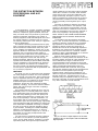
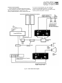
NOTE: The P-2200 actually has a maximum signal to noise ratio of 110dB
(which is its dynamic range!. The SYSTEM'S Dynamic Range is limited by
acoustic noise at the mic input, for the system shown, and by the maximum
signal to noise ratio of the PM-700 Mixer (93dB), a very respectable figure for
a high gain device.
Fig. 33 - Dynamic Range in an Audio System
The P-2200 is designed for these wide dynamic range
applications. It has exceptionally low noise figures, and
high headroom capabilities (high power output). In
addition, its operating levels and impedances correspond
with professional requirements.
GAIN OVERLAP AND HEADROOM
Yamaha PM-Mixers have +24dB (12.3 volts) maximum
output levels. This high output level is advantageous in
many situations. One reason is that it assures adequate
headroom for driving the input of any professional
device. High headroom is also important for a mixer that
feeds a professional tape recorder, and in a concert
sound reinforcement system.
Occasionally a "passive" device (no transistors or
tubes) is inserted between the Mixer and the power
amplifier in a sound reinforcement system, or in a
studio monitoring system. Examples of passive devices
are passive graphic equalizers, passive low level crossovers
(frequency dividing networks), pads and resistive isolation networks. Passive devices always attenuate the signal
level somewhat. For example, a passive low level crossover, when properly terminated, creates a 6dB loss
between the mixer and the power amplifier. Passive
graphic equalizers can create more than 6dB loss at
some frequencies. A mixer with +24dB output drive,
such as a Yamaha PM-Mixer, has considerably more output level than is needed to drive the inputs of most
amplifiers so that passive devices may be used as desired.
This extra output capability (above that needed to drive
the power amplifier) is known as "gain overlap," and is
one of the most important advantages of a Yamaha
PM-Mixer over other mixers, especially non-professional
mixers.
INPUT SENSITIVITY RATINGS
Some auxiliary devices have input sensitivities rated
like this: "nominal input sensitivity: +4dB." Others may
be rated like this: "input sensitivity: +4dB for rated
output." This later rating is typical of many power
amplifiers, including the P-2200. The difference between
these ratings is subtle, but very important. The first
device, has a nominal input sensitivity of +4dB (1.23
volts), and may be capable of peak levels far above +4dB
(1.23 volts); the actual headroom may be stated in
another specification. The second device (the P-2200 is
an example), has a peak input sensitivity of +4dB
(1.23 volts). A +4dB input signal to the P-2200 drives
it to full output. Thus, the user must be sure to carefully select the system's operating levels.
The gain overlap in mixer output drive capability and
power amp input sensitivity let the user choose a headroom figure for the P-2200; this will be typically 10dB
for speech or concert reinforcement, 1 5 to 20dB for
high quality music reproduction or recording. The discussion on Page SIX 5 illustrates the headroom adjustment process.
PROFESSIONAL EQUIPMENT ADVANTAGES
The many advantages of professional equipment
include: balanced lines for hum and noise rejection, low
impedance circuits for long cable runs, high operating
levels for maximum signal to noise ratio, high operating
headroom for low distortion and low noise, and reliable
XL-type connectors that are unlikely to be disconnected
accidentally and that tend not to hum or pop when
being attached. In addition, levels and impedances for
professional equipment are relatively standardized,
which, in many cases, eliminates the need for special
adapters, pads, transformers, or preamplifiers. For these
reasons, professional equipment, even though its initial
cost may be higher, will almost always benefit the user
on a long term cost/performance basis.
The P-2200 user realizes all of these professional
benefits. In addition the P-2200 can be used with many
hi-fi or semi-pro devices, such as guitar preamps, semipro or hi-fi tape machines.
Fig. 34 - Typical Gains and Losses in a System
INSTALLATION AND DETAILED
OPERATION
PHYSICAL MOUNTING
Shelf Mounting
The P-2200 can be used on any surface, so long as
there is adequate ventilation. Do not remove the
P-2200's feet, since this would prevent air flow below
the amplifier.
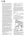
Permanent Installation Rack Mounting
Mount the P-2200 in any standard 19" electronic
equipment rack as shown to the right. Leave adequate
space between the P-2200 and other devices in the rack
for ventilation, and for expected cabling. Cooling fans
may be required when the P-2200 must produce
extremely high average power output, or when it is
located in a high temperature environment, such as a
closed outdoor building in direct sunlight.
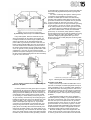
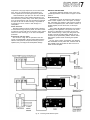
Rack Mounting for Portable Usage
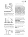
Road cases must be durable enough to survive heavy
cartage, and airline travel. Brace the rear of the P-2200,
and if the road case is small and ventilation is constricted, install cooling fans. One possible design is
shown in Figure 35.
Fig. 35 - P-2200 with Cooling Fans
Front fan panel view before folding.
Rear fan air containment panel front view, before folding.
P-2200 mounted in rack showing support brackets
made from bent pieces of 1/8" steel rod with nuts
welded to their ends.
Regarding Input Impedance and Terminations
There is sometimes a misunderstanding regarding the
nature of matching or bridging inputs, the use of terminating resistors, and the relationship between actual
input impedance and nominal source impedance. Most
electronic outputs work well when "terminated" by an
input (connected to an input) having the same or a
higher actual impedance. Outputs are usually overloaded
when terminated by an impedance that is lower than the
source impedance. When the actual input impedance of
the following device is nearly the same impedance as the
source, it is known as a "matching" input. When the
input of the following device is ten times the source
impedance, or more, the input is considered to be a
"bridging" input. There is hardly any loss of signal
level when an input bridges the source device, but a
matching input may cause a loss of 3 to 6dB in level.
Such losses, however, are normal and usually present
no problem.
It seldom is necessary to place a 600 ohm "terminating resistor" across any high impedance input (the
P-2200's input can be considered to be high impedance).
In fact, most 600-ohm outputs operate normally when
bridged by a high impedance; it is as though no load
were connected to the source device.
The only instance where a terminating resistor may
be required is when the manufacturer of the source
device specifically states that a terminating resistor is
necessary. In such cases, there is usually a special type
of output transformer in the source device, or the device
is constructed primarily of precision, passive components (no transistors or tubes), such as a passive
equalizer. In these cases, the terminating resistor assures
optimum frequency response in that device. Input
terminating resistors are not needed for the P-2200 to
operate correctly. If a 150 ohm or 600 ohm resistor is
specified for the source device, it should be installed at
the end of the cable nearest the P-2200 in order to
minimize possible hum, noise or signal losses in the cable.
CABLING AND IMPEDANCE MATCHING
Attenuation Pads
A "pad" is a resistive network that lowers the level in
an audio circuit. The most common professionally used
pads are "T-pads" and "H-pads." T-pads unbalance true
balanced lines (and floating lines), but work well in
unbalanced circuits. H-pads are best for balanced or
floating lines, but should not be used in an unbalanced
circuit since they will insert a resistance in the return
lead (ground). For a discussion of other types of pads,
refer to the AUDIO CYCLOPEDIA by Howard M.
Tremain (Pub. Howard W. Sams).
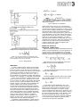
Fig. 37 - Where to Install a Pad when one is required.
Always install a T-pad near the input of the device it
feeds, with as short a length of cable as possible on the
low level side of the pad. This maintains a high signal
level in the longer transmission cable, minimizing any
induced hum and noise.
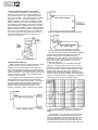
The low impedance pad values illustrated in Figure 38
are designed for 600-ohm lines. Commercially manufactured pads are available; consult your Yamaha dealer.
When connected between a 600-ohm or lower source
and a 600-ohm or higher termination, pad attenuation
values will remain fairly accurate. For higher impedance
circuits, resistor values must be changed. A 600-ohm pad
inserted in a high impedance circuit may overload the
device feeding the pad (the source device). Multiply the
given values by the output impedance of the source
device, and divide that answer by 600 to achieve the
desired value. The high impedance values listed for the
T-pads in Figure 38 are close approximations of average
hi-fi pads, based on 10,000-ohm nominal impedances.
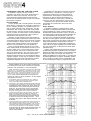
For low level circuits, use 1/4 watt resistors. For outputs with continuous sine wave levels above +24dBm,
use 1/2 watt resistors; for continuous sine wave levels
dB Loss
Fig. 36A - The Actual Voltage reaching the Load Device
is given by the Formula: (also see Appendix)
Fig. 36B - Where to Insert a Termination Resistor when one
is required.
0.5
1.0
2.0
3.0
4.0
5.0
6.0
7.0
8.0
9.0
10
12
14
16
18
20
22
24
26
28
30
32
34
36
38
40
50
R1 T (ohms)
R1 H (ohms)
300
560
1100
1710
2200
2700
3300
3900
4300
4700
5100
6200
6800
7500
7500
8200
8200
9100
9100
9100
9100
9100
10k
10k
10k
10k
10k
150
300
560
820
1100
1500
1600
2000
2200
2400
2700
3000
3300
3600
3900
3900
4300
4300
4700
4700
4700
4700
4700
4700
4700
5100
5100
16
33
68
100
130
160
200
220
270
270
300
360
390
430
470
510
510
510
560
560
560
560
560
560
560
560
620
8.2
18
33
51
68
82
100
110
130
150
150
180
200
220
220
240
240
270
270
270
270
300
300
300
300
300
300
R2
180k
82k
43k
27k
22k
10k
5.1k
2.7k
1.6k
1.2k
16k
1k
13k
11k
9100
8200
6800
5100
4300
3300
2700
2000
1500
1300
1000
820
620
510
390
330
240
200
62
820
680
560
470
430
360
240
200
150
120
91
75
62
47
36
30
22
18
15
12
3.6
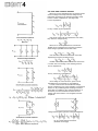
Fig. 38 - Attenuation Pad Construction and Resistor Values
for High Impedance (10K-ohm) and Low Impedance (600 ohm)
[shaded area) circuits.
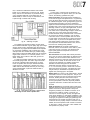
Transformers
Audio transformers (as distinguished from power
supply transformers, RF transformers or other transformers) are primarily used for ground isolation,
impedance matching and level matching. The following
paragraphs detail several applications of audio transformers at low signal levels. Speaker-level transformers
are discussed on Page SEVEN 6; the Appendix gives
further details on transformer operation.
Matching Transformer Box:
Impedance matching transformers can be used to
connect a high impedance source to a low impedance
load, or vice-versa (see Page SIX 5 for a discussion of
matching versus bridging inputs). The box shown below
may be used to run a 600-ohm balanced or floating line
to the P-2200 input, or it may be used between any
600-ohm source and high impedance input. Use a transformer capable of handling nominal +4dB (1.23V)
inputs with at least +24dB (12.3V) peak capability.
Fig. 39A - Pads Constructed in Mini-Boxes.
The transformer should be mounted in a mini-box,
wired to the XLR connectors with stranded wire, and
connected to the auxiliary equipment with one of the
cables previously illustrated. In line transformers, such
as those manufactured by Shure Brothers, Sescom, and
others may be used, with suitable adapters.
above +30dBm, use 1 watt, low inductance resistors.
10% tolerance is acceptable for most pads.
Fig. 39B - Pad Constructed in Switchcraft Model S3FM
It is possible to construct a pad within an XLR connector, but the extremely tight fit can adversely affect
reliability. The Switchcraft model S3FM is a tube with a
male A3M (XLR) at one end, and a female A3F (XLR)
at the other end. Pads using 1/4 watt resistors can be
constructed inside this device. Cover the entire pad with
insulation tubing before final assembly into the S3FM.
A "mini-box" fitted with male and female XLR connectors is an easy to build, rugged housing for a pad.
Use stranded wire for best results.
Illustrated are three typical pad construction techniques. For most applications, it will be sufficient to
construct only a few types of pads: 20dB, 24dB, and
40dB pads cover almost any requirement. Consult
Figures 37, 38 and 39 for schematic, construction and
resistor value information.
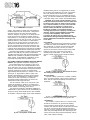
Fig. 40 - Matching Transformer Box
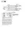
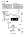
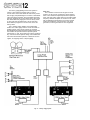
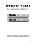
Step Up Transformer Box
The step up transformer box illustrated here is
similar to a pair of matching transformer boxes. This
configuration provides voltage step-up for optimum
drive levels when connecting the output of a low
impedance, low level source, such as the headphone
output of a mixer, to the two inputs of the P-2200. It
has a stereo phone jack input, but if the input source is
monaural, the transformer lead to the ring of the T.R.S.
input jack may be moved to the jack's tip so that a
standard T.S. phone plug input will feed both transformers. Alternately, the box may be built with separate
T.S. phone jack inputs, or with XLR inputs. Two
standard (2-wire) phone jacks outputs are provided for
connection to the "left" and "right" inputs of the
P-2200. Construct two cables from dual conductor,
shielded cable and T.S. phone plugs to connect the
transformer box output to the P-2200's input. Locate
the step up transformer box at least 5 feet from the
P-2200 to avoid hum pickup from the amplifier's power
transformer. However, the cables from the transformer
box to the amplifier should be no longer than 1 0 feet,
since this is a high impedance circuit. Use low
capacitance, coaxial, hi-fi type cable between the box
and the amplifier. Since the inputs of the P-2200 are
unbalanced, connecting two cables to its input forms
a short ground loop as shown in Figure 60 (see discussion of grounding on Page SIX 13). To keep hum
pickup at a minimum, run the two cables close
together; this minimizes the area (and therefore the
hum) enclosed by the loop.
The two diagrams show circuits using a Triad A-65J
transformer, and a UTC A-24 transformer. Similar 600
ohm to 15K-ohm transformers are acceptable. The 1/4
watt, 10%, 15K-ohm resistors are used to terminate the
transformers, for lower distortion, and improved
frequency response.
Bridging Transformer Box
When a single, low impedance, balanced source which
must remain balanced feeds several P-2200 inputs, the
TRANSFORMER AVAILABILITY
The matching and step-up transformers mentioned
in the preceding subsections are available from many
electronic parts dealers. Yamaha does not endorse
specific products by citing them herein; rather, these
transformers are mentioned for convenience only. If
you are unable to locate the transformers from your
local electronic parts dealer, contact the manufacturer
at the address shown below.
Sescom, Inc.
P. 0. Box 590, Gardena, CA 90247
Phone (800) 421- 1828 (213) 770-3510
Shure Brothers, Inc.
222 Hartrey Ave., Evanston, Illinois 60204
Phone 1 3 1 2 ) 323-9000 Cable: SHUREMICRO
Triad
305 N. Briant St., Huntington, Indiana 46750
Phone (219) 356-6500 TWX: 816-333-1532
UTC
150 Varick St., New York. NY 1 0 0 1 3
Phone ( 2 1 2 ) 255-3500 TWX: 710-581-2722
A line of very high quality transformers, suitable for the
most critical applications, is available directly from:
Jensen Transformer Company
10735 Burbank Blvd., North Hollywood, CA91601
Phone (213) 876-0059
Fig. 41 - Step-Up Transformer Box
bridging transformer box should be used. While matching
or step up transformers like those just described would
maintain a balanced feed, several such boxes could overload the source device. By using a transformer which has
a high impedance primary and a high impedance
secondary, the source can feed several P-2200 inputs
without being overloaded. Use one box for each
P-2200 input, paralleling the primaries (the primaries
are then fed from the single, balanced source; the
secondaries are connected to the P-2200 inputs). Construct the box in a similar manner to the Step Up
Transformer Box, or the Matching Transformer Box.
Fig. 42 - Bridging Transformer Box Schematic. Construction
is similar to Photos in Figures 40 or 41.
Input Impedance Matching for the P-2200
While the input impedance of the P-2200 varies
somewhat with the setting of the input attenuator, for
practical purposes, it is fixed at 25K-ohms. This means
that any source device feeding the P-2200 must be
capable of driving a 25K-ohm load without overload,
distortion, or failure. Any professional device, most
semi-pro equipment, and most hi-fi devices meet this
requirement.
When a single source device feeds the inputs of
several P-2200 amplifier sides, the effective load on the
source is equal to the parallel combination of all the
P-2200 input impedances. To avoid overloading a high
impedance source, use a resistor matching network, an
impedance matching transformer, or insert a line
amplifier with a lower output impedance between the
source and the P-2200's input.
Figure 43 shows the voltage division diagrams for
the output impedance of a source device and the input
impedance of the P-2200, when various impedance
matching devices are used.
Level Matching and Headroom (also see Page FIVE 2)
Headroom is the amount of level available above the
average (nominal) signal for peaks in the program. Noise
floor is the average noise level at any point in the
system. The difference in level between the peak output
of the system and its noise floor is the system dynamic
range.
Careful level matching can optimize the dynamic range
of the system (minimize the noise) and maximize the
headroom.
First choose a headroom figure. For maximum fidelity
when reproducing music, it is desirable to allow 20dB of
headroom above the average system output. While some
extreme musical peaks exceed 20dB, the 20dB figure is
adequate for most programs. A 20dB headroom figure
represents a peak level that is one hundred times as
powerful as the average program level. This means that
for an 8-ohm load, and a 20dB headroom figure, even an
amplifier as powerful as the P-2200 has to operate at an
average 2.3 watts output power. In some systems such as
studio monitoring, where fidelity and full dynamic range
are of utmost importance, this low average power may
be adequate. In other situations, such as 70-volt background music systems, a 20dB headroom figure is
undesirable and costly.
The choice of a headroom figure, then. depends on
the type of program material, the application, and the
available budget for amplifiers. For a musical application where high fidelity is the uppermost consideration,
1 5 to 20dB of headroom is desirable. For most sound
reinforcement applications, especially with large
numbers of amplifiers, economics play an important
role, and a 10dB headroom figure is usually adequate.
For these applications, a limiter will help hold program
peaks within the chosen headroom level, and thus avoid
clipping problems. For the extreme situation where
background music and paging must be heard over high
continuous noise levels, such as a factory, yet dangerously high sound pressure levels must be avoided, a headroom figure of as low as 5 or 6dB is not unusual. With
this low headroom figure, and the extreme amount of
compression and limiting necessary to achieve it without
distorting, the program may sound unnatural, but the
message will get through.
Fig. 44 - Headroom Adjustments
Fig. 43 - Voltage Division Diagrams
After choosing a headroom figure, next adjust the
incoming and outgoing signal levels at the various
devices in the system to achieve that figure. For the
simple system in Figure 44, the adjustments for a 20dB
headroom figure would be made as follows:
1. Initially, set the attenuators on the P-2200 at
maximum attenuation (maximum counter clockwise
rotation). Feed a sine wave signal at 1000Hz to the
mixer input at an expected average input level
approximately -50dB (2.45mV) for a microphone,
+4dB (1.23 volts) for a line level signal. The exact voltage is not critical, and 1000Hz is a standard reference
frequency, but any other appropriate frequency can
be used.
2. Set the input channel level control on the mixer
at its rated "nominal" setting, and adjust the master
level control so that the output level is 20dB below the
rated maximum output level for the mixer. For the
Yamaha PM-180 Mixer used in the example, the
maximum rated output level is +24dB (12.3 volts), so
the output level should be adjusted to +4dB (1.23
volts), as indicated either on an external voltmeter, or
on the mixer's VU meter (0VU).
3. Assume that the rated maximum input level for
the graphic equalizer in the example is +14dB (3.88
volts). Subtracting +4dB from +14dB leaves only 10dB
of headroom, so a 10dB resistive pad must be inserted
between the mixer output and equalizer input. Now, the
signal level at the input to the equalizer should be -6dB
(388mV), which can be confirmed with a voltmeter.
4. Assume that the maximum rated output level of
the equalizer in this example is +18dB (6.16 volts).
Adjust the master level control on the equalizer so that
the output level is 20dB below this rated maximum, or
-2dB (616mV). Since the equalizer has no VU meter,
you need an external voltmeter to confirm this level.
5. Finally, starting with the attenuators on the
P-2200 at maximum attenuation (maximum counter
clockwise rotation), slowly rotate them clockwise,
watching the peak reading meters. When the peak
reading meters indicate 2.3 watts output from the
P-2200, there is 20dB headroom left before clipping.
To operate this system, use only the controls on the
mixer, and avoid levels that consistantly peak the mixer's
VU meter above the "zero" mark on its scale, or that
peak the P-2200's meters above a safe power level for
the speaker system. Any adjustments of the other devices
in the system will upset the headroom balance. However,
the P-2200's calibrated attenuators allow easy setups
and quick changes, if you decide to change the headroom
figure. They also allow you to momentarily fade the
entire program or a single channel and to later bring it
back up to exactly the same level.
To use this technique with any system, first design
the required speaker system, and calculate the number
of power amplifiers needed to safely operate the
speaker system with adequate headroom. Then, choose
the mixer, and other devices that feed the power
amplifiers, and set up the system according to the above
instructions.
In some cases, it may be useful to set up different
headroom figures in different parts of a complex
system. For example, background music and paging
should be severely compressed in a noisy lobby area,
but the same program material would sound more
natural in less noisy office and auditorium areas of the
same installation if the headroom figure were increased.
By placing a compressor/limiter in the circuit just before
the P-2200 that feeds the lobby areas, the headroom
figure can be lowered for that section only, without
affecting other parts of the system.
Cabling the System
Audio circuits may be divided into the following
classifications (by signal level):
1. Low level circuits: any circuit carrying signals of
-80dB (77.5 microvolts) to -20dB (77.5 millivolts),
example: microphone lines.
2. Medium or line level circuits carrying signals of
-20dB (77.5mV) to +30dB (24.5 volts), example:
mixer outputs.
3. High level circuits carrying signals above +30dB
(24.5 volts), example: speaker lines.
4. AC power circuits, including lighting circuits.
5. DC control (or supply) cables to relays, from
batteries, etc.
Generally, each of these categories should be
physically separated from the others to avoid crosstalk,
oscillation, and noise spikes. One possible exception is
that DC control or supply cables and line level signal
cables can be routed together if the DC signal is
adequately filtered. Figure 45 shows the undesirable
results that can occur if line or speaker cables are placed
near microphone cables. This situation occurs in concert
sound when mixer outputs and mic inputs feed through
the same "snake" cable.
Fig. 45 - Example of Crosstalk
Figure 46 shows an equipment rack with a good
cable layout. Note that the different categories of cable
are carefully separated, and that where it is necessary
to cross two categories, they cross perpendicular to each
other. These suggestions apply to all types of systems,
portable as well as permanent.
Fig. 46 - Cable Routing in Equipment Rack. (Reprinted
from Sound System Engineering by Don & Carolyn Davis
published by H. W. Sams Co.)
Figure 47 shows the rear of a P-2200 amplifier with
its two inputs "chained" using a phone-to-phone cable.
In this mode, the signal fed to the first side is also fed to
the second side of the amplifier. This could also be
accomplished with an XLR-to-XLR cable.
For low and medium level balanced signal cables, use
good quality twisted pair shielded cable. For portable
use, a cable with rubberized insulation and braided
shield (such as Belden #8413 or #8412) will handle
easily and survive road abuse; for permanent wiring,
a vinyl insulated cable with a foil shield (such as
Belden #8451) is easier to strip for terminations, and
it pulls through conduits with less drag.
Fig. 47 - "Chaining" of Inputs
For unbalanced, signal level cables, use low capacitance shielded cable with a good quality (high percentage
density) shield. Again, rubberized types work best for
portable use, vinyl types with foil shields are acceptable
for permanent installations (the foil shield may crack
and split under the constant flexing of portable usage).
Many single conductor shielded cables have an extremely
fragile center conductor. To avoid this problem, use a
higher quality dual conductor cable and ground one
center conductor.
For high level speaker cables and DC control cables,
use heavier gauge cable. The chart in Figure 48 shows
the effects of different sized wired gauge on power
losses in speaker cable. Except in extreme RF fields
(radio frequency interference), speaker and control
cables will not need shields; when they do, use heavygauge shielded cable, or place the cables in steel or
aluminum conduit.
*Approximate. depends on wire type.
Fig. 48 - Chart showing the effects of different Sized
Wired Gauge on Power Losses in Speaker Cable.
Connectors
In many cases, connectors will be dictated by the
types of equipment in the system. When you can make
choices, the following guidelines may help.
Phone Connectors are an audio industry standard connector used for signal and speaker lines. T.S. (tip/sleeve)
types, like those used as inputs on the P-2200, are used
for unbalanced signals; T.R.S. (tip/ring/sleeve) types are
used for balanced signals, or for stereo unbalanced
signals such as stereo headphones. Phone connectors are
generally easy to wire, and the metal types provide good
shielding. However, for high power applications, such as
the output of the P-2200, many phone plugs do not
have rated current capacities high enough to avoid some
power loss. Also, some phone plugs have a brittle
insulator between the tip and sleeve which can break if
the connector is dropped, resulting in a tip to sleeve
connection which is a direct speaker line short circuit.
For this reason, phone jacks have not been used for the
P-2200 output. If you have an amplifier with a phone
jack output, military grade phone connectors, while
more expensive and somewhat harder to wire, are the
best choice for avoiding these problems.
Phono Connectors are not usually considered professional, and are not included on the P-2200. If phono
connectors are part of a system, they should be the
higher quality types with a separate cover such as
Switchcraft#3502.
XLR Connectors are another audio industry standard.
They come in several configurations for different types
of cabling, and can be used for either balanced or unbalanced connections. Three wire types, like those used
as inputs on the P-2200, are the most common. XLR
connectors are generally very durable, and are well
shielded. The three wire types have the added
advantage that pin#1 always connects before pin
#2 or #3 so that the ground or shield wire connects
before the signal carrying wires. This allows any static
charges built up on the shields to equalize before the
signals meet, reducing pops in the system.
Banana jacks are common in the audio industry, and are
a standard connector for test equipment. They do not
provide any shield, and can be reversed in their socket.
However, banana jacks, like those used as output
connectors on the P-2200, have high current ratings,
and are good speaker connectors, especially inside an
equipment rack where occasional disconnections must
be made.
Other Connectors are occasionally used in audio work.
Standard, electrical twist-lock types have been used for
speaker connections, although there is always the
dangerous possibility of a mistaken connection to an
AC power line. Multi-pin "snake" connectors are
common for low level signals, but may be fragile and
need careful handling. For permanent installations, and
for permanent connections in portable equipment racks,
crimp type (as opposed to solder type) spade lugs and
terminal strips may actually provide the best type of
connection since a properly crimped connection is more
reliable, and lower impedance than a solder connection.
A "hard wire" or direct connection is also reliable and
low impedance if properly made.
The preparation of complete cables, with connectors
properly installed, is the key to reliable and trouble-free
operation of any sound system. For this reason, the following illustrations are included. Experienced audio
technicians may wish to review these illustrations, even
if they already know how to wire connectors. A few
moments of extra care here can save hours of troubleshooting later on.
As a rule, the amount of insulation removed and the
length of exposed cable should be minimized. This
reduces the likelihood of short circuits and improves the
ability of the clamp to grip the cable firmly. Enough
heat should be used to obtain a free flow of solder, but
allow leads to cool quickly after solder flows to avoid
melting insulation. After each connector has been com-
pletely wired, the cable should be tested with an ohmmeter or a cable tester. Continuity between the various
conductors and their associated connector pins must be
established, and there should be infinite resistance (an
open circuit) between all connector pins. In most cases,
especially in portable installations, XLR connectors
should not conduct at all between the shell and pin 1.
This avoids grounding problems from inadvertent touching of the shell to other devices.
Cables to be connected to terminal strips should be
prepared by stripping the ends and installing crimp-on
or preferably, solder type lugs. If there is any chance
the cable will be strained, use a cable that is constructed
with internal strain relief cord, such as Belden No. 8412.
Crimp a lug onto the cord, and secure the lug to an unused terminal. (The cord should be drawn slightly
tighter than the wire leads in order to take the strain
first.)
WIRING AN RCA-TYPE PIN PLUG*
Parts identification and cable preparation.
Strip approximately 1/2" of outer insulation. Unwrap
or unbraid the shield and form a lead. Strip approximately 5/16" of insulation from the center conductor.
Tin both leads.
Solder the shield to the outer surface of the shell
connection, allowing enough free shield to wrap the
cable around to the center of the connector. Cool
the connection immediately with pliers.
Insert the center conductor in the hollow pin, and
fill that end with solder. Cool the connection immediately with pliers. Clean any solder splashes and inspect
for burned insulation. Pinch the clamp around the outer
insulation with pliers, firmly, but not so tight as to cut
the insulation.
Slide the shell forward and screw it tightly to the
threaded plug.
*Switchcraft No. 3502 connector illustrated. Many large
diameter cables are more easily wired to "simple" RCA
type pin plugs without a shell (Switchcraft No. 3501M, or
equivalent). The braid can then be soldered directly to the
shell of the plug.
WIRING A MALE XLR CONNECTOR
Pans identification (as the connector is usually
packaged).
Insert strain relief in rear of shell. Then slip shell
onto cable end, followed by insulating collar. Strip outer
insulation 1/2". (No. 8412 cable illustrated here.)
Cut tracer cord, unbraid shield, cut cotton strain
relief cords.
Strip approximately 1/4" of insulation from center
conductors, tin, and trim to approximately 1/8" exposed wire. Then twist shield, positioning it in the
correct orientation to mate with the insert. After tinning the shield, cut it to the same length as the center
conductors.
Solder the center conductors to their respective pins,
using just enough solder to fill the end of the pins.
Yamaha's wiring standard dictates that the black lead
mates with pin 3 and the white (or red) with pin 2
(see footnote on page 10 of this section). Then solder
the shield to pin 1 . Clean any solder splashes and inspect
for burned insulation.
Slide the insulating collar forward, up to the flange of
the male insert. The outer cable insulation must be flush
with, or covered by the end of the insert. If any of the
center conductors are visible, the cable clamp may not
be able to firmly grip the cable. Then slide the collar
back into the shell.
Slide the shell forward, orienting its internal keying
channel with the raised lip (key) on the insert. Secure
the insert in the shell with the set screw. Place the cable
clamp over the rear of the shell, with careful attention
to the clamp's orientation; a raised lip inside the clamp
should be aligned immediately over a lip in the shell for
thinner cable (No. 8451). The clamp should be turned
around for heavier cable (No. 8412) to provide clearance.
Insert the clamp screws and tighten fully.
WIRING A FEMALE XLR CONNECTOR
Parts identification (as the connector is usually
packaged).
Insert strain relief in rear of shell. Then slip shell
onto cable end, followed by insulating collar. Strip outer
insulation approximately 9/16". (No. 8451 cable illustrated here)
Pull off foil wrap. Strip approximately 5/16" of
insulation from the center conductors, leaving approximately 1/4" of insulation between the bare wire and
the outer insulation. Tin the center conductors, and
trim so that about 1/8" bare wire remains. Then tin the
shield conductor, orienting it with the center conductors so they are aligned with the proper pins of the
insert. Cut the end of the shield so that it extends 1/16"
beyond the center conductors.
Solder the center conductors to their respective pins,
using just enough solder to fill the end of the pin.
Yamaha's wiring standard dictates that the black lead
mates with pin 3, the white (or red) lead with 2 (see
footnote on page 10 of this section). Then solder the
shield to pin 1 . Clean off any solder splashes, and inspect
for burned insulation. Insert the locking tab in the
female insert, as illustrated, with small nib facing front
of connector.
Slide insulating collar foward, up to rear edge of
female insert. The outer insulation of the cable must be
flush with, or covered by the end of the insert. If any of
the center conductors are visible, the cable clamp may
not be able to grip the cable firmly, and the connector
leads will soon fatique. Then slide the collar back into
the shell.
Slide the shell forward, orienting the notch in the
shell with the locking tab in the insert. Secure the insert
in the shell with the set screw. Place the cable clamp
over the rear of the shell, with careful attention to the
clamp's orientation; a raised lip inside the clamp should
be aligned immediately over a lip in the shell for thinner
cables (No. 8451). For heavier cables (No. 8412), the
clamp should be turned around to offset the lips and
provide more clearance for the cable. Insert the clamp
screws and tighten fully.
WIRING A STANDARD PHONE PLUG (2-conductor)
Parts identification.
Slide shell, then insulating collar over cable end. Strip
outer insulation for length equal to length of sleeve connection. Unwrap or unbraid shield, twist to form lead.
Position outer insulation just ahead of cable clamp,
strip center conductor from point just behind tip connection. Tin center conductor and shield. Bend shield as
illustrated, solder to outer surface of sleeve connection.
(Cool immediately with pliers.) Insert center conductor
in tip connection, solder, cut end flush. Bend the end of
the tip connector (slightly) toward the sleeve connection
to help prevent the burr (from the cut wire) from cutting through the insulating collar.
Using pliers, bend cable clamp around outer insulation. Clamp should be firm, but not so tight as to cut
insulation.
Slide insulating collar forward, until flush with rear
of threads. Slide shell forward, screw tight to plug
assembly.
WIRING A TIP, RING &
SLEEVE PHONE PLUG (3-conductor)
Parts identification.
Slide shell and insulating collar over cable end. Strip
outer insulation for length equal to length of sleeve connection. Remove any tracer cords and strain relief cords.
Form lead from shield. Hold cable with outer insulation
just ahead of cable clamp, and strip the red (or white)
conductor just behind the tip connection. Then strip
the black conductor just behind the ring connection.
Tin all leads, and cut the center conductors so approximately 1/8" of bare wire remains.
Solder the shield to the outer surface of the sleeve
connection, allowing enough free shield to bend around
to the other side of the cable clamp. Cool the connection immediately with pliers.
Insert the center conductor leads in their respective
connection points, and solder in place. Trim the leads
flush. Bend the end of the tip connection (slightly)
toward the ring connection to help prevent the burr
(from the cut wire) from cutting through the insulating
collar.
Using pliers, bend the cable clamp around the outer
insulation. The clamp should be firm, but not so tight
as to cut the insulation.
Slide the insulating collar forward, until flush with
rear of threads. Slide the shell forward, and screw tightly
onto plug.
Use of the Input Polarity Switch on the P-2200
The XLR input connectors on the P-2200 are unbalanced. In one position, the switch beside the connectors attaches pin 2 to pin 1 (ground) leaving pin 3
"hot" (USA standard). In the other position, the switch
attaches pin 3 to pin 1 (ground) leaving pin 2 "hot"
(DIN/JIS standard). If the source feeding the P-2200's
input is unbalanced, the switch must be properly set to
avoid shorting out the source. If the source is balanced,
the P-2200's inputs will unbalance the source. In many
situations, this is acceptable, however, the input polarity
switch must still be set in the position corresponding to
the "hot" pin of the balanced source. If the switch is
set in the wrong position, the signal will be inverted at
the P-2200's output compared to the signal at the
source ("out-of-phase"),
Fig. 50B - Equivalent Circuit: Speaker Impedances in Series.
Fig. 50C - Circuit as seen by One Speaker of Series Pair.
Fig. 49 — Polarity Switch Use
Output Impedance Matching
Within its rated power and voltage limits, the P-2200
acts very much like a perfect voltage source (see
Appendix). Thus, as the impedance of the load goes
down, the total power delivered by the P-2200 goes up.
Figure 4, Page FOUR 1 illustrates this action. Note that
when the impedance of the load falls below 2.5 ohms, the
P-2200's protection circuitry begins to limit the total
amount of power delivered.
For purposes of calculating the total load impedance
that is presented to the P-2200, assume that speaker
impedances do not change with frequency. The Appendix shows various series and parallel combinations of
speakers and the effective loads they present to the
P-2200. Formulas for the power delivered to each
speaker in a parallel or series combination are included.
Fig. 50A - Speakers in Series
Note that a series connection of two speakers degrades
the damping factor (see Page FOUR 7) because each
speaker looks back at the amplifier through the
impedance of the other speaker. Thus the effective output impedance of the P-2200 as seen by one speaker is
equal to the actual output impedance of the other
speaker (see Figure 50).
Also, the impedance of most speakers lowers with
frequency, so that the effective load of two "8 ohm"
speakers in parallel across the output of the P-2200 may
be as low as 2.5 to 3 ohms at certain frequencies. Thus,
speaker loads much lower than 8 ohm nominal impedance could overload the amplifier, especially if the
actual impedance drops far below the nominal impedance.
Figure 51 shows the variation of impedance magnititude
with frequency for one type of speaker system.
Fig. 51 - Free-Air Impedance of Typical " 8 " Loudspeaker.
NOTE: Impedance changes when loudspeaker is installed in a
cabinet.
The impedance of 70-volt speaker transformers also
falls with frequency, especially in lower quality transformers. (Note that a "perfect" transformer would not
have any impedance of its own.) If low efficiency 70volt transformers are used, the system will need more
transformers and speakers to achieve the same SPL than
if higher quality transformers were used. Thus,
"economy" transformers, may actually cost more in
the long run than higher quality professional types.
For an existing system with lower quality 70-volt
transformers, a capacitor in series with the output of
the P-2200 can limit the current at low frequencies
(see Page SEVEN 6), and thereby avoid the possibility of
constant protection circuitry operation on the
P-2200, or damage to the 70-volt transformers from
excessive output power from the P-2200.
Transients and DC Protection
The P-2200 displays virtually no turn-off transient,
and the turn-on transient is minimal. A DC voltage at
the input will not be amplified (Figure 27, Page
FOUR 4), thus protecting speaker loads against damage
from DC at the output of the P-2200.
GROUNDING AND SHIELDING
Definitions
Ground: A general term, used in various ways throughout the audio industry. It can mean the same as "common," "earth," "chassis" or "return."
Earth: A connection made to the actual soil or dirt.
Also a connection made to a cold water pipe or any
other device that ultimately enters the soil (and that can
provide a very low impedance path to the soil).
Fig. 52 - Impedance of Poor Quality 70-Volt Speaker
Transformer (Connected to 8
looking into Primary).
Speaker, Tapped for "5 Watts,"
Common: The "return" wire of an audio pair; any
point where several such return wires connect with each
other. There can be "signal commons," "DC power
supply commons" or "AC power supply common"
(neutral). A common wire may or may not be connected to ground or earth. Similarly, the AC power
supply ground may or may not be connected to the
audio system common or to earth.
Shield: A metallic shell around a cable, amplifier, or
other device that helps prevent the entrance of unwanted interference.
ACTIONS OF THE P-2200 PROTECTION CIRCUITS
The P-2200 has several features that contribute to the
protection of the amplifier and its loudspeaker load:
Grounding: The process of careful connection of
common, shield, ground, and earth connections to
avoid unwanted hum and noise.
Fuses
The AC line fuses protect the P-2200 from excessive
AC line voltage and, in the unlikely event of an internal
failure, the AC line fuses protect the amplifier from
severe damage. Always replace blown fuses with the
same size and type. If the fuses blow consistently, the
P-2200 should be checked by a qualified technician.
Ground Loop: If a common or return signal can travel
from one point to another via two or more paths, the
resulting circular path is called a "ground loop."
Figure 53 shows two possible ground loops in an
audio system.
Grounding
The third wire on the AC line cord is a "ground" wire.
This wire connects the chassis of the P-2200 to AC
ground for safety. Do not defeat this safety feature
unless other methods have been employed to ensure a
good earth ground.
Thermal Protection
There is a thermal fuse, located inside the P-2200's
power transformer, that shuts down the AC power to
the P-2200 if the temperature of the transformer windings reaches 130° Centigrade. A thermal warning light,
on the front panel, turns on when the P-2200's heat
sink temperature reaches 100° Centigrade. Special heat
compensating circuits in the P-2200 insure that the
amplifier will perform properly within its operating
temperature limits.
Overload Protection
The P-2200's overload protection circuits limit the
maximum power available to drive any load. The effect
of these circuits is to smoothly limit the power to loads
below 2.5 ohms. The overload protection circuit action
is virtually inaudible, even when driving difficult, multispeaker loads. Figure 4, Page FOUR 1 and Figure 15,
Page FOUR 3 graph the power output of the P-2200 for
varying load impedances.
Fig. 53 - Two possible Ground Loops in an Audio System.
RFI: RFI (radio frequency interference) comes from
any number of sources, including radio stations, CB
radios, SCR (electronic) light dimmers, neon lights
and others, RFI may show up in a sound system as a
radio program, as a hum or buzz, or other noise. RFI
often enters a sound system at a low level preamplifier
stage. Many RFI problems can be cured by careful
grounding and shielding, and by the use of balanced,
twisted pair cables.
EMI: EMI (electro-magnetic interference) usually comes
from power transformers (either in a sound system, or
a building's electrical supply), motors, or cables carrying
large amounts of current. EMI usually shows up in a
sound system as a hum or buzz. Twisted pair, balanced
lines effectively reject most EMI. Whenever possible
avoid placing sensitive equipment near motors or transformers (keep input transformers several inches away
from the P-2200's power transformer), and use twisted
pair balanced lines.
Careful grounding and shielding can minimize
externally caused hum and noise. These techniques,
in essence, are to use balanced lines, use shielded cables,
and eliminate ground loops.
Use of Balanced Lines
Balanced lines are discussed in the Appendix. This
paragraph summarizes their advantages over unbalanced
lines for noise rejection. Balanced lines reject RF and
electro-magnetic interference by phase cancellation
between the conductors; twisted conductors aid the
rejection. Balanced lines help avoid grounding problems
because the shield does not carry any signal current
(this is explained further in following paragraphs). Also,
any noise currents entering the shield cannot directly
enter the signal path because the shield is not part of
the signal path (in contrast to an unbalanced line, where
the shield is the signal "return" wire).
Use of Shields
An effective shield also aids noise rejection. The
shield effectiveness of many types of cable is specified
in percentage of density. A close braided shield can be
highly effective, but may be more expensive and is
harder to work with than foil shields. Foil shields, in
most cases, are more suitable for permanent cable connections since they are easier to prepare. Many guitar
cables, especially the coiled type, have poor shields and
are the source of much of the hum common in guitar/
amplifier systems. A poor quality cable may also exhibit
"microphonics," a condition where movement of the
Ground loops, are a common source of noise pickup.
Figure 55 shows the way noise enters a system through a
ground loop. One common source of ground loops in a
sound system is the double grounding path between
equipment caused by AC grounding the chassis of each
piece of equipment, and then making a second ground
connection between the two chassis via the signal cable
shield. Figure 53, Page SIX 13 shows this problem. Figure
56 shows a method of avoiding this type of ground loop
in a system by using what is known as a "telescoping
shield" connection where each piece of equipment is
AC grounded for safety, but a potential ground loop is
avoided by connecting the signal shield at one
end of the cable only. Traditionally, the shield is connected at the "far" end of the cable, so that shield
currents "drain" in the same direction as the signals
flow. Figure 58 shows a similar connection using unbalanced lines. The AC grounds on each device have
been "lifted" so that the only ground connection
between two pieces of equipment is the shield of the
signal cable. Since, in an unbalanced cable, the shield
carries signal current, it cannot be disconnected. Moreover, in this type of unbalanced grounding scheme, if
the shield becomes disconnected inadvertently at some
point along the signal path, some pieces of equipment
will not have an AC ground, so safety is compromised.
Fig. 55 - Noise Entering System through Ground Loop
cable can cause noise in the sound system.
Fig. 56 - Telescoping Shield
Fig. 54 - Poor Quality Shielded Cable
Metal equipment racks, and metal electrical conduits
are also effective shields against RF noise. However, few
shields offer really effective protection against electromagnetic interference (EMI). Solid iron conduit and,
possibly to a lesser extent, steel conduits and racks do
offer some protection. Fortunately, however, most EMI
interference can be effectively avoided by keeping
sensitive wiring and equipment away from large power
transformers, electric motors, etc., and by using
balanced, twisted pair cabling whenever possible.
Fig. 57 - Feeding the Input of the P-2200 from a Balanced
Source without a Balancing (Bridging or Isolation) Transformer.
Unbalancing the source at the P-2200's input (CHAN A
Diagram) will usually result in lower hum levels than unbalancing
the source at the source (CHAN B Diagram).
Fig. 58 - Avoiding Ground Loops in an Unbalanced System.
In any audio system, there are numerous ways by
which ground loops can be created. For example, if a
microphone feeds two mixers through a splitter device,
and the two mixers are AC grounded through their
power cables, a ground loop is formed. In this case, it's
better to lift the shield leading from the microphone to
one of the mixers than to lift the AC ground of one of
the mixers. This procedure not only preserves the safety
of the AC ground, but may actually provide better noise
suppression. If you learn to look for these potential
problems as a system is designed, you can avoid much of
the last-minute troubleshooting that is so often necessary
to get rid of hum and noise.
a cold water pipe running through a water meter that has
been electrically bypassed does provide a good ground
connection.
It is worth mentioning that systems without ground
connections may be capable of interference-free
operation. Portable tape recorders and other batteryoperated, self-contained audio equipment are not earth
grounded. The electronics in airplanes are not grounded
to earth (at least not when they are flying), yet the
equipment operates well. The purpose of earth grounding
a sound system is to keep the chassis of all equipment
at the same potential as the AC mains ground for safety.
Connecting the same unbalanced input signal to both
inputs of the P-2200 causes a small, but unavoidable
ground loop. To avoid hum pickup problems, keep the
area enclosed by this loop as small as possible by running
the two cables to the input close together. If the two
inputs are "bridged" (tied together with a phone-tophone or XLR-to-XLR cable) keep the connecting cable
as short as possible.
Fig. 60 - Minimizing Hum with Unavoidable Ground Loops.
Fig. 59 - Avoiding a Potential Ground Loop when using two
Mixers and a Mic Splitter.
For safety reasons, the final ground point in a system
should actually be earth ground. Electrical codes always
require that the building's AC ground be connected to
earth ground (at the building's AC service entrance). By
connecting the sound system ground to earth, instead
of connecting it to some arbitrary three-prong AC outlet, you avoid any noise that may be traveling along the
building AC ground wire, and you are assured of a good
ground for safety, even if the AC ground wire at the
outlet is interrupted (see Page SIX 16). A good earth
connection can be obtained at a cold water pipe, or by
driving a long metal rod into moist ground. Hot water
pipes (which are usually disconnected electrically from
earth at the hot water heater), PVC pipes (which do not
conduct electricity), and connections to cold water pipes
which must travel through a water meter before entering
the earth are poor choices for earth grounding. However
Grounding on the Road
Many of the above procedures are difficult to use on
the road. For example, the telescoping shield concept is
nearly impossible to use on a portable cable. Similarly, it
is a difficult and time consuming process to search for a
water pipe ground every time the system is moved from
one performance to another. Yet portable systems can
be extremely complex, and may have major grounding
problems.
The telescoping shield concept can be extended to
portable systems by installing a "ground lift switch" on
the output of each device, and on the inputs of devices
after the mixer (since microphones are not grounded
except through the mixer, there is no need for an input
ground lift switch on most mixers). Figure 61 shows a
typical ground lift switch installation. By judicious use
of these switches, each piece of equipment can be AC
grounded for safety without causing ground loops.
Because of leakage currents from equipment in the
system, and in the house, some noise currents can ride
on the AC ground wire, and are able to enter the audio
Fig. 61 - Use of Ground Lift Switch
system. This problem is usually most noticeable with
sensitive equipment such as the mixer. Lifting the AC
ground at the mixer can often solve this problem.
However, lifting the AC ground on the mixer also lifts
the AC ground on the microphone chassis, causing a
safety hazard. Try connecting the mixer and any other
sensitive equipment to other AC circuits. The only other
apparent solution to this problem is to eliminate the
noise on the AC ground, which is not an easy task. A
portable AC power distribution system with its own
ground, connected to the house service entrance, may
be the most effective way to avoid all AC noises. Such
a system can be designed and constructed by a qualified
electrician; check local electrical codes before each use.
Perhaps the best answer to portable system grounding
problems, RFI, EMI, and AC noises, is to develop a
versatile grounding scheme with ground lift switches and
adapters, and, if possible, a portable AC power distribution system, so that different combinations can be
tried easily and quickly when a problem occurs.
AC: POWER, FUSES, ACCESSORY OUTLETS, WIRING,
SAFETY (Not applicable in 220/240 Voltage area.)
The P-2200 requires an AC voltage of 105V AC to
135V AC, 50 or 60Hz. If the voltage falls below 105V
AC or rises above 135V AC, the P-2200 will not operate
properly, and may be damaged. At full power with both
channels operating into 8 ohms, the P-2200 draws
approximately 960 volt-amperes, or 8 amps at 120V AC
(see Figure 12, Page FOUR 2). When a system uses
several P-2200 amplifiers, check the current capacity
of the AC line, and distribute the amplifiers among
several AC circuits, if necessary. It is extremely
important to always replace blown AC fuses in the
P-2200 with the same type and value.
The AC accessory outlets on the rear panel of the
P-2200 are provided for operation of cooling fans or
other low power equipment, not for the connection of
another P-2200, or other high power device.
The American Electrician's Handbook published by
IvlcGraw Hill is a good reference for an understanding of
proper AC wiring. Other smaller books, often available
in hardware or electrical supply stores, detail simplified
residential wiring. We do not suggest that you modify
the AC wiring in an auditorium or a club, or anywhere
else. Such work should be reserved for a qualified,
licensed electrician. But, if you understand proper AC
wiring, you will also understand the potential problems
of improper wiring, some of which are described below.
CAUTION: In any audio system installation, governmental and insurance underwriters' electrical codes must
be observed. These codes are based on safety, and may
vary in different localities; in all cases, local codes take
precedence over any suggestions contained in this
manual. Yamaha International Corporation shall not
be liable for incidental or consequential damages,
including injury to persons or property, resulting from
improper, unsafe or illegal installation of the P-2200
or of any related equipment; neither shall the
Corporation be liable for any such damages arising
from defects or damage resulting from accident, neglect,
misuse, modification, mistreatment, tampering or any
act of nature.
Lifted Ground
Broken, or disconnected AC ground wires in existing
AC outlets can create shock hazards; so can older, twowire sockets with no ground. Note that unless metal
conduit connects the older, two-wire AC outlet to
ground (an uncommon practice except in some public
buildings), the screw on the outlet cover plate is
probably not grounded either. In this case, an AC
ground, or earth ground must be located somewhere
else.
Fig. 62B - 110VAC Outlet with Disconnected AC Ground
Wire creating potential shock hazard.
Reversed Polarity
Improper polarity connections, or polarity modifications, can cause reversal of the "hot" and "neutral" AC
wires. This can cause shock hazards, and noise in some
equipment.
Fig. 62C - 1 1 0 V A C Outlet with Polarity (Hot and Netural)
Reversed creating shock hazard and causing possible noise.
Fig. 62A - Properly Wired 110VAC Outlet
Lifted Neutral
The "neutral," or return, wire of a 1 1 0 V AC circuit
should be connected to AC ground at the building
service entrance (where the main AC power enters).
However, this neutral is usually a center tap from a 220V
AC circuit; if it becomes disconnected at the service
entrance, a varying voltage will appear at the AC outlet,
which may rise as high as 220V AC, depending on the
load on each circuit. This poses shock hazards, and can
easily cause equipment damage.
Fig. 62D - 1 1 0 V AC Outlets with Lifted Neutral. Outlets will
operate with voltage varying from 0 to 220V AC creating shock
hazard and causing possible equipment damage.
220V AC on 1 1 0 V AC Outlet
It is possible (albeit, illegal and dangerous) for a
220V AC circuit to be connected to a 1 1 0 V AC outlet
as shown in Figure 62E. Fortunately, this rarely occurs.
In an older building, it may have been done to allow
1 1 0 V AC wiring to carry the 220V AC voltage needed
to run lighting equipment. If the P-2200, or some other
audio device, is plugged into such an outlet, the AC line
fuses will blow almost immediately, but some equipment
may still be damaged. In addition, this type of outlet
poses a shock hazard.
Fig. 62E - 1 1 0 V AC Outlet with a 220V AC Circuit
connected to it. This is a highly dangerous and illegal connection.
1 1 0 V AC Outlet Connected to Dimmer Circuit
Possibly more common than the 220V-wired 1 1 0 V
outlet is the connection of a 1 1 0 V AC stage outlet to a
lighting dimmer circuit. This may have been done to
allow lighting to be controlled on stage from a remote
location. An outlet connected to a dimmer is a poor, if
not illegal, practice and the light dimmer can decrease
the voltage in the circuit. Some dimmers are capable of
raising the AC voltage. In either case, audio equipment
connected to the circuit may suffer damage, and shock
hazards are also possible.
Fig. 62F - 1 1 0 V AC Outlet connected to a Light Dimmer
Circuit, a dangerous and illegal connection.
The best way to avoid all kinds of AC mains problems, for permanent or portable systems, is to check
the voltage and polarity of the outlet yourself - before
plugging in any audio equipment. Three wire AC circuit
testers are available at most hardware and electrical
stores, and will allow easy polarity and ground
continuity checking of all outlets. While these testers
may show that an outlet has an extreme over-voltage
condition (the tester may burn out), the tester may not
show less extreme, but still serious, over-voltage conditions. Also, even though such testers may display
continuity to ground at the third pin of the AC outlet,
the resistance in the ground may still be high enough to
warrant the use of a separate earth ground. Thus, it is
also a good idea to carry a small voltmeter for verifying
the actual voltage at an AC outlet, and to establish a
direct path to earth ground that does not rely on the
AC mains. Some commercially available AC plug
strips have an AC voltmeter built in, or you can install
a panel mount meter that reads voltage before equipment is connected to the AC circuits in an equipment
rack.
Even if the voltage and polarity of the AC outlet are
correct, the line may be "soft," that is, it may not be
capable of sustaining proper voltage under load. Monitor
the AC line voltage when the P-2200 is operating near
full power. If the AC line voltage falls below the
minimum rated for the P-2200 (105 volts RMS), the
P-2200 will not operate properly, and could conceivably
sustain damage.
Lifting the AC ground to an audio device, while it
may solve some noise problems, also lifts the safety
feature for which the AC ground was originally
designed. If you must lift the AC ground, be certain
that the AC ground is carried through to that piece of
equipment via the shield of a signal cable, or by some
other means.
Other Safety Considerations
While it may seem obvious, the P-2200 does weigh
44 Ibs (20kg), and should be adequately mounted to
prevent it from falling onto other equipment or people.
Also, while less obvious, the speaker output terminals
of the P-2200 can deliver as high as 57 volts RMS, and
under certain conditions, this could present a shock
hazard. It is common practice in the audio industry to
use "male" connectors to carry output signals, and
"female" connectors for inputs. For speaker level
signals, however, it may be safer to reverse this convention, or to use "recessed male" type connectors as
outputs to avoid the possibility of coming into contact
with the high voltage output of the P-2200.
MONO OPERATION
Connections
Connect a mono input signal, such as a single output
from a mixer or other source, through a splitter transformer to both of the P-2200's inputs as shown in
Figure 63A. Switch the POLARITY SWITCH on one
channel opposite that of the switch on the other channel
(one switch grounds pin 2 to pin 1 ; the other switch
grounds pin 3 to pin 1 ) .
This connection provides equal signals to each of the
P-2200's inputs with one input out of phase with the
other (reversed in polarity).
Connect the speaker load to the two red terminals
(+) on the P-2200's outputs as shown in Figure 63B.
Do not connect either speaker wire to ground as this
would short out one channel of the P-2200, and would
severely cut the power available to the speaker load.
Fig. 63A - Input Splitter Transformer Setup to Operate P-2200 in "Mono" Mode.
Fig. 63B - Output Connections for Operating P-2200 in
"Mono" Mode.
In the "mono" mode, the P-2200 will produce a full
400 watts into a 16-ohm load. The voltage output from
the P-2200 in the mono mode is approximately 75
volts RMS, and since it can drive even highly reactive
loads with complete stability, it is suitable for driving
70-volt (constant voltage) commercial sound speaker
lines. In all but very small systems, the P-2200 can offer
cost savings when compared to multiple, low-power
amplifier installations. In addition, the P-2200's performance specifications far exceed most commercial
sound amplifiers. Figure 76 illustrates a typical 70-volt
constant voltage system (also called a "distributed"
system since there are usually a number of speakers
distributed throughout a building).
APPLICATIONS
BIAMPLIFICATION AND TRIAMPLIFICATION
Biamplification, or "biamping," triamplification, or
"triamping," all refer to the use of separate power
amplifiers to cover separate portions of the audio
spectrum.
The traditional, non-biamplified speaker system is
diagrammed in Figure 64A. The crossover network,
which routes the high and low frequencies to their
respective speakers, is located in the circuit between the
power amplifier and the speakers. A large system may
contain many power amplifiers, crossovers, and speakers.
Figure 64B diagrams a biamplified speaker system,
showing the crossover located in the circuit before the
power amplifiers, and showing a separate power
amplifier for the high and low frequencies. A triamplified
system has an extra crossover section, another power
amplifier, and a woofer, midrange and tweeter.
The crossover for a biamplified system is a low level
crossover since it processes low power signals. It may
also be called an active or electronic crossover since it is
usually an active device (using transistors, tubes, and/or
IC's). Some low level crossovers are passive (no transistors, tubes, or IC's). All high level crossovers used in nonbiamplified speaker systems are passive, and they must
process the full power of the power amplifier.
There are any number of good reasons for taking a
biamplified or triamplified approach to a professional
sound system. One reason is that a biamplified system
can actually provide more headroom per watt of
amplifier power than a system with a traditional (high
level) passive crossover.
Headroom
Program material (music or speech) is made up of
many different frequencies and their harmonics. Most
music, especially popular music, is bass heavy; that is,
the low frequency material contains much more energy
than the high frequency material. When both high and
low frequency material, such as a flute and a bass guitar,
are present in a program, the high energy bass frequencies can "use up" most of the power in a power
amplifier leaving none for the high frequencies. The
result can be severe clipping (distortion) of the high
frequency material. With an electronic crossover, the
high frequency material can be routed to its own power
amplifier, avoiding the clipping problem. This results in
an effective increase in headroom that is greater than
would be obtained by simply using a larger, single
power amplifier.
Figure 65A shows a low frequency waveform from a
power amplifier output. The peak-to-peak voltage of
the waveform is 1 2 1 volts, corresponding to 43 volts
RMS. If this voltage were applied to an 8-ohm speaker
load, the power level would be 230 watts, which is equal
to the peak output of Yamaha's P-2200 professional
power amplifier into an 8-ohm speaker load just before
clipping occurs.
Figure 65B shows a high frequency waveform from a
power amplifier output. The peak-to-peak voltage, RMS
voltage, and power into an 8-ohm speaker load are less
than shown in Figure 65A and correspond to a 1 6 watt
output into an 8-ohm load. The levels of these high and
low frequency waveforms are typical of musical content.
Figure 65C shows the effect of adding the signals of
Figure 65A and Figure 65B, corresponding to a low frequency note and a high frequency note being played at
the same time. Note that the total peak-to-peak voltage
(which would be 153 volts if it were not clipped) is
greater than the peak-to-peak voltage of either signal by
itself. For an amplifier to produce this voltage into an
Fig. 64A - System using Conventional, Passive/High-Level
Frequency Dividing Networks.
Fig. 64B - Biamplified System using Yamaha F1030
Electronic Frequency Dividing Network.
Fig. 65 - Advantages of Biamplification
8-ohm load, it must be rated at 366 watts (power is
proportional to voltage squared). Since the P-2200 is
only capable of 230 watts, this waveform is clipped,
especially the high-frequency component.
If the same two waveforms in Figure 65A and
Figure 65B were reproduced by two separate amplifiers,
the total amplifier power capacity needed would only
be 246 watts (the sum of the two powers), not 366 watts.
This power could be provided by one P-2200 and one
smaller amplifier. Thus, using two power amplifiers to
produce these two waveforms reduces needed amplifier
power capacity. Or, if you use two P-2200 amplifiers,
there is a substantial increase in headroom.
Efficiency
A passive crossover is made up of resistors, capacitors,
and inductors. The resistors in the crossover "use up"
some power as do the losses in the capacitors and
inductors. By removing the passive crossover, these
losses are also removed.
Damping
Damping was discussed on Page FOUR 7. With reference to that discussion, any impedance inserted between
an amplifier's output terminals and a speaker's input
terminals reduces the damping factor; a passive crossover
is such an impedance. Thus, biamplification, by removing the passive crossover, improves the effective
damping factor.
Distortion
It is conceivable that a passive crossover could
introduce some distortion which could be avoided by
removing the crossover. However, the greatest reduction
of distortion comes with the increased headroom in biamplified systems, which means less peak clipping in
the amplifiers.
Dynamic Frequency Response Shift (also Page FOUR 6)
When the peaks of a complex waveform are clipped
off by inadequate headroom, two things happen. First,
since these peaks are usually high frequency information
(see Headroom discussion), the high frequencies are lost,
or reduced severely. At the same time, the clipping
creates new harmonics of the input frequencies. These
two factors can be considered to be changing the
frequency response of the system on a dynamic
(changing) basis, depending on the amount of clipping
present.
When to Use a Traditional, Passive Crossover
In small sound systems, where high sound levels are
not needed and economy is a major consideration, a
speaker system with a traditional, passive crossover network may be the best choice. For example, Yamaha's
S4115H and S0112T are excellent as stage monitors, or
as main speaker systems for small to medium sized clubs.
For larger installations, a biamplified or triamplified
system will not only perform better than a system with
passive crossovers, but will probably cost less too; the
increased efficiency and headroom allows fewer
amplifiers and speakers to produce the same sound
level, and fewer crossovers are required.
Realizing the Advantages
To realize the advantages of a biamplified or triamplified system, the electronic crossover must be able
to work well with a variety of different power
amplifiers and speaker systems. In addition, because it
plays a critical role in the sound system, the electronic
crossover must be highly reliable, and its performance
must be as good, or better than any other component
in the system. Yamaha's F1030 electronic frequency
dividing network (electronic crossover) meets these
needs. It is an excellent choice for any biamplified or
triamplified system.
Criteria for Biamped Systems
Crossover Frequency and Slope:
There is a freedom of choice available to the designer
of the biamplified (or triamplified) system that is not
available to the designer of a non-biamplified system. The
added advantage of being able to choose crossover frequency and slope means that the system can be carefully
optimized for a specific application, or it can be made
highly versatile for use in a wide variety of applications.
Most manufacturers of quality speaker components
carefully specify both power capacity and frequency
range. The choice of crossover frequency can be based on
this information. For example, if a high frequency
driver's power capacity is rated at 20 watts of pink noise
from 2kHz to 20kHz, a crossover frequency of 2kHz or
higher is a good choice. A lower crossover frequency
might allow over-excursion of the driver's diaphragm,
leading to premature failure. If the system is biamplified, the woofer will be chosen to complement
the high frequency driver's response. If the system is
triamplified, both a woofer and a midrange driver or a
super tweeter must be selected so that the frequency
ranges of all the components complement each other.
Preferably, there should be some overlap in the frequency range of each successive driver.
The choice of crossover slope involves a tradeoff
between speaker protection and phase shift. A low slope
rate of 6dB/octave will produce a smooth
system response with minimum phase shift,
but it may not adequately protect high frequency
drivers from excessive low frequency energy or low
frequency drivers from excessive high frequency energy.
A high slope rate of 24dB/octave or higher will protect
the drivers better, but can introduce more phase shift
than a crossover with a lower slope rate. 12dB/octave
and 18dB/octave are widely used, and are good compromises. 12dB/octave is the most common choice, but
18dB/octave can provide a little "extra protection" for
sensitive components, especially high frequency drivers.
Again, decisions should be based on a careful study of
the abilities of the individual components, and of the
system requirements.
One common method of designing a three way
system (with woofers, midrange, and high frequency
drivers) is to biamp the system between the woofers and
midrange, and to then use a passive, high level crossover
between the mid and high frequency drivers. Since there
is generally less energy in the high frequency range, the
extra headroom and efficiency that would be obtained
by triamping may not be needed. This compromise will
usually save money without adversely affecting performance or reliability.
Criteria for Selection of a Crossover (Dividing Network)
There are only a few passive, high level crossovers on
the market that are suitable for professional sound
systems. Those that are built into a finished speaker
system, such as Yamaha's S 4 1 1 5 H and S0112T, are
exceptions. Because of the limited selection, a custom
designed system with passive high level crossovers
usually has to be designed around the crossover instead
of around the drivers. Still, the crossover should meet
certain criteria. It should have an impedance equal to the
desired speaker system impedance (the impedance of the
woofer, midrange and tweeter must be the same for most
passive, high level crossover systems). If possible, choose
the crossover frequency and slope by the criteria
described in the previous paragraphs. Also, choose a
passive, high level crossover with adequate power
handling (for reliability), good quality components (for
low loss and low distortion) and with rugged physical
construction.
The designer of a biamplified (or triamplified)
system must choose an electronic crossover from an
expanded set of criteria. A professional electronic crossover should meet the professional criteria described on
Page FIVE 1 for balanced inputs and outputs, and for
input and output levels and impedances. In addition, in
order to be usable in a variety of professional systems, an
electronic crossover should give the designer a choice of
crossover frequencies and slopes. Some electronic crossovers restrict the choices, or require hardwired changes
or plug in cards to choose different frequencies or slopes.
Yamaha's F1030 is a two way or three way electronic
crossover which gives the designer a wide choice of
crossover frequencies selectable for each of three bands
by means of front panel controls. The controls are
recessed to avoid accidental setting changes. Either
12dB/octave or 18dB/octave slope rates can be selected
by internal switches. The F-1030 meets all the criteria
for a professional unit, and, in addition, has both XLR
and phone jack input and output connectors.
ECHO, REVERB, AND DELAY
Artifical echo is usually obtained in either of two
ways, with a tape delay (similar to a standard tape
recorder) or with a digital delay unit. Repeated echoes
are obtained by feeding some portion of the delayed
output back to the echo input (regeneration), or by using
multiple output taps along a tape or digital delay path.
In a tape recorder, the delay results from the time it
takes for the tape to travel from the record head to the
playback head (or heads). In a digital delay unit, the
audio is converted to a computer-like digital code (using
an analog-to-digital converter), delayed by shift
registers, and then reconverted to audio (using a digitalto-analog converter). Other methods of obtaining time
delay are available, from "bucket brigade" (analog) time
delay units to a simple, effective technique where a
microphone is inserted in one end of a length of tubing
and a speaker at the other end.
Besides its use as an effect, a time delay device can be
a very useful tool in commercial sound systems. If two
speaker systems, which are fed by the same signal, are
separated by more than about 30 feet, a listener can
hear a distinct echo. By slightly delaying the signal to
the speaker system nearest the listener, such echoes are
avoided. This situation is presented in the Applications
section, in the diagram for a typical system in a theatre
with a primary speaker system at the stage, and a
secondary system under a balcony (which cannot be
covered directly by the stage speaker system).
COMPRESSION AND LIMITING
Dynamic range (also see Page FIVE 2) is the difference in dB, between the highest and the lowest volume
levels in any audio program. A compressor is a device
that shrinks that dynamic range. The "threshold" of a
compressor is the level above which compression begins.
The "compression ratio" is the ratio of output level
change, to input level change, in dB, for any program
material above the threshold. A limiter is a compressor
with a high compression ratio (usually 1 0 : 1 or higher).
Often a single device can be used for either compression
or limiting, since the distinction depends mainly on the
threshold and ratio settings.
Radio stations use compressors and limiters. Limiters
keep audio peaks from overmodulating and distorting
their broadcast signal (an FCC requirement), and compressors keep their average modulation levels high (in
order to reach the maximum audience).
The dynamic range of better quality magnetic tape
recorders is about 65dB. Since much live program
material has a dynamic range of 90dB or greater, a
recording studio can use a compressor/limiter to restrict
the dynamic range of a program to fit the dynamic
range of the tape medium. Special "noise reduction"
devices are available for tape recording that make use of
complementary compression and expansion to lower
the noise levels on a tape recording and to retain the
original dynamic range of the program.
In a paging system, a compressor can keep the
average level of different announcers' voices more constant so that paging can reach noisy areas of a factory
or airport more consistently. In addition, because of
reduced dynamic range, peaks are lowered, reducing the
chance of clipping distortion.
In concert sound reinforcement, or other large sound
reinforcement systems, a compressor/limiter can reduce
the chance of peak clipping, and can thus help avoid
amplifier or speaker damage from large turn-on/turn-off
transients, or from sudden, loud feedback. These uses of
compressor/limiters are valid for recording studio
monitoring as well as for sound reinforcement (although
feedback should not be a problem in studio monitoring).
Fig. 66 - Biamplified System showing Placement of
Optional Limiters.
While useful, compressors (compressor/limiters) are
not cure-all devices. The compressor "makes its
decision" to begin compressing by continuously
monitoring the program level. Unfortunately, the
highest levels are usually low bass notes. Thus the compressor/limiter may compress the high frequencies
needlessly when it detects a bass note that is too loud.
One solution to this problem is to use a compressor on
each output of an electronic crossover on a biamplified
or triamplified system so that the compressor acts only
on the frequencies in each band. This method requires
two or three devices and is probably not applicable to
broadcast. Another solution is to use a separate compressor on each mixer input that receives excessive
program levels.
Another problem with a compressor is that if it is
over-used, it can reduce the quality of sound in a musical
performance. Reduced dynamic range is often audible
and a poor quality compressor can add appreciable
distortion to a program, especially at high compression
ratios.
EQUALIZATION, HIGH AND LOW PASS FILTERS
Equalization, originally, was the process of
"equalizing" the levels of the various audio frequency
bands for a "flat" system response. The term now
encompasses many different devices and techniques
that are used for effects purposes as well as to "smooth"
the response of a system.
Room Equalization
A room, whether it be a recording studio, concert hall,
airport lounge, or night club, has a frequency response of
its own. Carpeting, draperies, and padded furniture can
soak up sound, primarily at high frequencies. The high
reverberation time of large concert halls usually affects
the low frequency sounds more than the high frequency
sounds. For these, and other reasons, it may be desirable
to shape the frequency response of a sound system to
compensate for the response of the room.
Generally, acoustic solutions are the best answers to
these acoustic problems, especially for severe resonances
or excessive peaks or dips in the room response. However,
for final smoothing of system response, or for portable
systems where acoustic solutions may be impractical,
electronic room equalization can be a valuable aid.
There are several different methods of room equalization. Most methods use a specified sound source, such
as pink or white noise, or a tone burst which is played
through the system. The sound is monitored at some
point (or at several points) in the room using a real time
monitoring device (real time means that the monitor
displays the system response on an instantaneous basis).
A graphic equalizer, or other type of equalizer is used to
adjust the system response to compensate for response
irregularities displayed on the real time monitor.
Equalization can also help to smooth the response of
a speaker system, a microphone, or most any type of
audio device. However, this can cause problems, as
explained below. These frequency response shaping
techniques can also be used for special effects: to
increase the sizzle of a cymbal crash, to sweeten the
sound of a violin or to add warmth to a singer's voice.
Equalizers come in all types and varieties. Some are
most suitable for a specific task, others have more
general uses.
Graphic Equalizers
A "graphic" equalizer is a multi-frequency, band
reject filter or a bandpass/reject filter. Unlike the input
channel equalizers on a mixer, a graphic equalizer can
simultaneously operate at several 1-octave, 1/2-octave, or
1/3-octave frequency bands. Most graphic equalizers use
l.S.O. standardized center frequencies. (I.S.O. is an
acronym for the International Standards Organization.)
The units are called "graphic" because most have linear
slide controls, and when they are set they create a visual
image that resembles the overall frequency response
curve of the unit. Some so-called graphic equalizers use
rotary controls. A graphic equalizer may provide attenuation only (band reject), or attenuation and boost (band
pass/band reject).
Usually, each speaker feed requires its own channel of
professional-type graphic equalization which is installed
between the mixer output and the power amplifier input.
Stage monitor feeds, for example, may require very
different equalization than house feeds. In recording and
broadcast applications, the graphic equalization applied
to the recording is usually for tonal considerations, and
to avoid exceeding the frequency response limits of the
Graphic Equalization can be used to reduce resonant peaks
in the overall sound system (which consists of the microphones,
instruments, room and speakers. 1-octave EQ illustrated.)
NOTE: Shaded area represents sound level above which feedback will occur. If any frequency is reproduced at a level in the
shaded zone. then either the overall sound level must be turned
down (lower volume), or the graphic equalizer must be used to
reduce the level of the frequency band where the excess level
occurs. Proper selection and placement of microphones and
speakers can reduce the need for equalization. "He who equalizes
least equalizes best" (anon.).
A. A microphone picks up a vocal peak at 1kHz, making it
necessary to reduce the average level (horizontal dotted
line) to some 5dB below the feedback point.
B. Lowering the 1 kHz Graphic EQ slider about 5dB pulls down
the resonant peak and allows the overall volume to be raised
several dB. Any further increase of the volume control may
cause feedback to occur at several frequencies where lesser
peaks occur: an electric bass at 125Hz an acoustic guitar
resonance at 500Hz, and a stage monitor speaker peak at
2kHz that is being picked up by a nearby microphone.
C. To allow the average level to be raised further, the 125Hz,
500Hz, and 2kHz Graphic EQ sliders are pulled down
slightly. This smooths the overall frequency response and
allows maximum loudness throughout the audio spectrum.
A natural roll-off at the low and high ends remains, and is
preferred by many users. If flatter response is required, it can
be achieved.
D. If the input channel tone controls were used to bring up the
high and low ends of the spectrum, too much lift would
occur toward the middle, causing feedback. Also. too much
overall bass boost would waste amplifier power and might
lead to burned out speakers or excess distortion. By lifting
the 62.5Hz, 8kHz and 16kHz Graphic EQ sliders slightly, the
response is flattened without unwanted distortion, and
without creating feedback.
Fig. 67 - How to Use 1-Octave Graphic Equalization
medium. At the same time, the studio monitors or
audience foldback system might require graphic equalization to suit very different ends.
Professional graphic equalizers are usually more
durable than hi-fi type units, and they operate at nominal
+4dB (1.23 volts) line levels. The input of a hi-fi type
graphic equalizer will probably require padding for use
with professional type mixers such as the Yamaha PMMixers, and its output level may be too low to drive
some common power amplifiers (the P-2200's
sensitivity is high enough to allow it to be driven by
most hi-fi type graphic equalizers). Aside from level
and impedance criteria, some graphic equalizers have
characteristics that cause the overall response curve to
change drastically when one frequency band is adjusted,
so two or more bands must be adjusted to preserve a
smooth response. Other equalizers maintain a smooth
transition to adjacent bands when just one control is
adjusted.
Parametric Equalizers
A parametric equalizer is one whose "parameters"
can be varied to suit the application. The parameters
include such factors as filter bandwidth ("Q"), center
frequency, and amount of boost or cut. Usually there
are several filters, and some "parametrics" are set up
for stereo operation. Each filter section in the
equalizer can either cut or boost frequencies within
its band, and the ranges of center frequencies available
from adjacent filters usually overlap.
pedals," "phasers," "flangers," etc. Each of these devices
was designed for a special purpose.
Fig. 69 - Actions of Tone Controls
High pass and low pass filters are special purpose
devices. They are sometimes called "horizontal" filters
because they do not boost or cut in the same manner as
a graphic or parametric equalizer (which would be a
"vertical" filter).
High pass filters, which pass frequencies only above
their "cut off" frequency, are used to cut low or subsonic frequencies from a sound system. Using a 40Hz or
80Hz high pass filter, for example, reduces dangerous
dropped-mic, or turn-on, turn-off transients, etc., but
allows all significant program frequencies to pass.
A low pass filter, which passes frequencies only below
its "cut off" frequency, can stop high frequency
oscillations and certain RF interference from reaching
the speakers.
In commercial sound systems, high and low pass
filters cut unneeded frequencies from the system, and
thus increase the total capacity of the system to
reproduce the frequencies of interest.
Fig. 68 - Actions of a Parametric Equalizer
By adjusting a filter for wide band rejection characteristics (low Q), it can perform room equalization in a
similar manner to a graphic equalizer, or it can act as a
variable frequency cut or boost tone control. In a
narrow band reject mode (high Q), a parametric
equalizer can be used for feedback control, or to notch
out hum frequencies without subtracting much of the
adjacent program material.
Used carefully, a parametric equalizer can be an
extremely helpful tool for sound reinforcement or for
recording. It should be remembered that, like a graphic
equalizer, excessive boost may reduce system headroom,
create clipping and make extreme power demands on
amplifiers and speakers. In addition, a parametric
equalizer may "ring" at high-Q (narrow bandwidth)
settings. Ringing is caused when a filter begins to act like
an oscillator. While ringing may be useful as an effect,
it may cause unwanted peaks in the system's frequency
response curve.
Other Equalizers
Tone controls are another type of equalizer. So are a
number of the special effects devices, like "wah-wah
Fig. 70 - Actions of High and Low-Pass Filters
Equalizer Problems
The previous discussions illustrate some of the many
uses of the various types of equalizers. Like any signal
processing device, equalizers can also cause problems.
From the power amplifier's viewpoint, the most
significant problem that can be caused by an equalizer
is clipping of frequencies that have been boosted to
extremes. If these boosted frequencies are in the treble
range, the clipping may sound like an irritating sizzle
that only happens on certain sounds. Similarly, clipping
in the low frequencies can cause bass notes to sound
fuzzy or muddy, or it can cause mid-range frequencies
to be harsh. Yet because the clipping only takes place
on certain sounds, it may not be immediately apparent
that clipping is the source of the problem. With graphic
equalization, the choice of a cut-only device (rather than
a boost and cut device) may help solve the problem
because, since boost is not available, clipping problems
are reduced. With cut and boost graphics, parametrics, or
other types of equalizers, the system operator must be
aware of the potential clipping problem, and attempt to
avoid it.
SPEAKER PROTECTION
The maximum sustained output power of the P-2200 into an 8-ohm load is at least 230 watts. Few, if any, single
speaker systems are capable of absorbing that much
power on a continuous basis. Most speaker systems,
however, are capable of absorbing short duration peaks
of considerably higher power than their rated continuous
power capacity. The ability to produce these peaks without distortion is a major advantage of a large power
amplifier like the P-2200. The speaker, however, must
be protected against the abuses of excessive average
power, sudden large peaks, DC current, and frequencies
outside its range. The following are methods of achieving
some degree of protection against these abuses.
Fuses
Yamaha does not recommend the use of any type of
fuse as speaker protection. Fuses are slow-acting devices
of inconsistent quality, and do not offer adequate protection for speaker systems. They are mentioned here
only because they are used in some systems. Standard
fuses may be capable of protecting a speaker against
excessive average power, but they are too slow to
successfully protect a speaker against sudden peaks.
Fast-blow, instrumentation fuses, with improved time
response, may blow on normal program peaks and
needlessly disrupt the program. Slo-blo fuses, on the
other hand, may not blow quickly enough to prevent
loudspeaker damage due to voice coil overheating. If
fuses are used, whenever possible fuse each loudspeaker
separately so that a single fuse failure will not stop the
show.
A fuse will protect a loudspeaker against one common
fault of a DC coupled amplifier: DC at the output. The
slightest DC offset from a direct coupled preamplifier
will be amplified and appear at the power amplifier's output as a larger voltage with the power amplifier's large current capacity behind it. Even though there is no immediate
audible affect (the extra power draw may cause some
amplifiers to hum slightly), the loudspeaker is forced to
absorb the DC power output of the amplifier. Since it
cannot convert this DC power into acoustic power, the
speaker overheats. Small amounts of DC voltage can
shorten the life of a loudspeaker, and any large amount
of DC will cause sudden, catastrophic failure. Fortunately, the input of the P-2200 is not DC coupled so any DC
voltages from preamplifiers, etc. are not amplified, and
cannot reach the speaker. The only time DC voltage
could appear at the P-2200's output would be in the
event of a severe electronic failure inside the amplifier,
a very unlikely event.
Capacitors
Inserting a non-polarized capacitor in series with a
high frequency driver can protect it against excessive
low frequency energy. The capacitor acts as a 6dB/
octave high pass filter. Especially on a biamplified
system, this kind of protection is desirable. For a biamplified system (or triamplified system), choose a
protection capacitor by the following formula:
Value (in microfarads) =
(Where " p " =3.14, "f" is the crossover frequency
divided by two, and Z is the nominal impedance of
the driver.)
The same formula can be used to choose a
capacitor to insert in series with a low quality 70-volt
speaker transformer to avoid excessive current flow at
low frequencies (see Page SIX 13). Measure the impedance of the transformer primary at the lowest frequency
of interest (which will probably be somewhere around
100Hz) with a speaker load connected to the secondary.
Choose the protection capacitor by the above formula
with Z = the measured impedance of the transformer,
and f = the lowest frequency of interest divided by two.
The voltage rating of the capacitor chosen must be
greater than the maximum expected total peak to peak
voltage that will ever appear at the driver's terminals.
For the P-2200, this is equal to the sum of its positive
and negative supply voltages, which is 160 volts. The
most common types of capacitors used for driver protection are non-polarized electrolytics. Because of the
inductance associated with an electrolytic capacitor, it
may be paralleled with a mylar capacitor of about 1 / 1 0
the value in microfarads to reduce high frequency losses.
Limiters
A limiter is not normally considered a loudspeaker
protection device, but it may be one of the best and most
practical. A "squared up" or "clipped" waveform causes
a loudspeaker cone or driver diaphragm to move to one
position and stay there, then move back to the extreme
opposite position, and stay there, etc. Because there is
still power flowing through the voice coil, but there is no
voice coil movement, the power is converted to heat. If
a limiter is placed before the power amplifier in a system,
it can be adjusted to prevent peaks from reaching a level
that would cause the power amplifier to clip, which may
avoid burned out loudspeakers.
Transformers
The 70-volt transformers used in "constant voltage"
commercial sound systems lend a certain amount of
protection to a loudspeaker. They will not pass DC
current, and most of them will not even pass subsonic
Fig. 71 - Typical use of Auto-Transformer for Speaker
Impedance Matching which also helps protect the Speaker
from damage caused by DC at the Amplifier's Output.
frequencies or very high frequencies, such as RF oscillations. Some 70-volt transformers have attached protection capacitors for use with high frequency drivers.
"Auto-transformers" (all taps from the same winding)
are sometimes used to match speaker impedances. The
auto-transformer provides many of the same protections
as a 70-volt transformer, with the exception that because
the taps are all from the same winding, it is possible for
a small amount of DC current to leak through to a
loudspeaker.
Passive Crossovers
Because a passive crossover usually inserts a capacitor
in series with the high frequency driver, and often inserts
an inductor in series with the low frequency driver (which
limits the current reaching it), it can aid in loudspeaker
protection.
High Pass and Low Pass Filters
The functions of high and low pass filters were discussed on Page SEVEN 5. Because these filters limit the
subsonic and supersonic frequencies reaching the loudspeakers, they can help prevent loudspeaker damage.
SPECIFIC APPLICATIONS
The following diagrams illustrate a few of the many
possible applications of the P-2200 in all types of sound
systems.
Studio Monitoring
The diagram in Figure 72 shows the P-2200 used as a
studio monitor amplifier. Part of the system is biamplified. Alternately, the Yamaha F1030 crossover could be
used for a triamplified system, with another P-2200 or a
smaller amplifier, such as the P-2100, for the super
tweeter.
The P-2200's dB-calibrated attenuators are a distinct
advantage in this application. The operator can reduce
the level of a particular set of monitors (such as the
studio monitors during a "take") and bring them back
up later to exactly the same setting. Settings can be
confirmed by the peak reading meters, and the meters
also help the operator avoid overdriving the speaker
systems.
Its high power output, exceptionally low distortion,
wide bandwidth and low phase shift, combined with its
high reliability make the P-2200 an ideal choice for a
studio monitor amplifier.
Fig. 72 - Recording Studio Monitor System
Concert Sound
Figure 73 illustrates the P-2200 in a typical setup for
concert reinforcement. Note that there are a number of
completely separate feeds, with separate limiters,
equalizers, electronic crossovers, and power amplifiers.
The P-2200's peak reading meters are a special
advantage in concert sound systems. They indicate the
amount of headroom left in the system, and help the
operator avoid clipping distortion, and possible speaker
system damage. Individual parts of the system can be
easily checked during setup, by turning down the calibrated attenuators on all other parts of the system. When
check out is finished, it's easy to bring back the levels
to previous settings.
Due to its high power output capability, the P-2200
is less likely to damage speaker systems as a result of
peak clipping. At the same time, the P-2200's AC
coupled input will not pass dangerous DC signals,
further protecting speakers.
Besides having exceptional specifications, the P-2200
is extremely reliable, and is built to take the abuses of
the road. Bracing the rear of the P-2200 in a portable
rack will "ruggedize" it for the most extreme cartage
requirements. In addition, the P-2200's protection
circuits smoothly limit power during severe thermal
and power demands (see Page SIX 13).
Fig. 73 - Concert Sound System
Portable Instrument Amplifier
Figure 74 details possible connections for a portable
setup for an electric bass. Ideal for this application, the
P-2200 can easily reproduce the high power bass notes
that may be clipped off by lower power instrument
amplifiers. Thus, it will "clean up" a bass sound, and,
because clipping is dangerous to speaker systems, the
P-2200's high power output may be easier on a speaker
system than a low power amplifier. In addition, the
P-2200 is sensitive enough (and its input is high
impedance) that it can be driven by the output of many
hi-fi or semi-pro type preamps. Its peak reading meters
help the musician avoid overdriving a speaker system,
and the calibrated attenuators allow the instrument
amplifier system to be turned down during a "break"
without modifying any of the preamp settings.
All of these advantages hold true when the P-2200 is
used as a keyboard amplifier, with the additional
advantage of true stereo operation.
Fig. 74 - Instrument Amplifier
Discotheque
Disco systems, such as the one diagrammed in
Figure 75, really test an amplifier's endurance. The
music from a record album may be highly compressed
so that its average power content is high, and the
amplifier may not get even a short rest during many
hours of operation each night.
With its massive heat sinks, and high average
power output capabilities, the P-2200 is an ideal amplifier for disco use. In addition to reliability, the P-2200's
low distortion will produce clean sound, the kind of
sound that avoids listening fatigue - an important
consideration for high sound level operation.
Fig. 75 - Combination Disco/Live Club Sound System Setup
Commercial Sound Systems
Figure 76 diagrams a theatre reinforcement system
from the viewpoint of its power amplifier. Note the time
delay device that feeds the P-2200 for the underbalcony distributed speakers. This P-2200 is connected
for "mono" 70-volt operation; the main P-2200 is
connected for biamplified operation. In a smaller
theatre, a single P-2200 might cover both areas, feeding
speaker systems with passive crossovers.
Fig. 76 - Theatre Reinforcement System
The factory paging/background music system in
Figure 77 also shows the P-2200 used in "mono"
70-volt mode. One P-2200 feeds the main factory areas
with a highly compressed signal. The other P-2200 feeds
office areas with a separate, less compressed signal that
has been equalized for a more natural sound. This setup
also allows selective paging into office or factory areas,
or into both areas simultaneously, and it could also
allow different programs to be fed to the office and
factory areas.
The P-2200 is highly reliable, and exceptionally
stable, even under highly reactive 70-volt line loads. In
smaller systems and in larger systems, the P-2200's
dB-calibrated attenuators and peak reading meters help
the installer and operator achieve optimum system
performance. In fact, the P-2200 can improve just about
any commercial sound system design, from auditoriums
and other reinforcement systems, to electronic church
organs, to shopping center or airport paging.
Other Uses
The P-2200 is a basic tool for all types of sound
systems. Yet its uses are not limited to sound systems
alone. The P-2200's exceptional performance specifications, and high power output make it an excellent audio
frequency oscillator amplifier for test bench use, which
will not degrade the performance of even the highest
quality test oscillators, noise generators, tone burst
generators, function generators or other equipment.
Fig. 77 - Factory Paging System
APPENDIX
dB SPL expresses an acoustic pressure (not power).
The 0dB SPL reference is 0.0002 dynes/square cm,
which is the approximate threshold of human hearing
at 1kHz.
NOTE: Since SPL values in dynes/square cm are uncommon, an example is not given.
DEFINITION OF TERMS: dB, dBV, dBm and dB SPL
The term dB, which means decibel ( 1 / 1 0 t h of a Bel)
expresses a ratio. The dB notation allows us to represent
very large ratios with small numbers which are easier
to understand and use. The ratio in dB of two power
levels is equal to 1 0 times the (base 10) logarithm of
their simple numeric ratio:
d B = 1 0 log P1 / P2
The ratio in dB of two voltages (V 1 and V 2 ) or
sound pressure levels (P1 and P 2 ) is equal to 20 times
the logarithm (base 10) of their simple numeric ratio:
d B = 2 0 l o g V 1 / V2
Examples:
Power: The ratio in dB of 100 watts and 50 watts.
dB = 10 log 100/50
Answer: +3dB
Note that this means that 100 watts is 3dB above 50
watts. If we had compared 50 watts to 100 watts (dB =
1 0 log 50/100), the answer would have been -3dB.
Similarly, any time the ratio of two powers is 2:1, their
ratio in dB is +3dB. When the ratio is 1:2, the ratio in
dB is -3dB.
Voltage: The ratio in dB of 100 volts to 50 volts.
dB = 20 log 100/50
Answer: +6dB
Note that a ratio of 2:1 in voltage means a ratio in
dB of +6dB. If the ratio is 1:2, the ratio in dB is -6dB.
SPL: SPL ratios, expressed in dB, are similar to voltage
ratios. For example, two SPL levels with a numeric ratio
of 2:1 would have a ratio in dB of +6dB. SPL ratios are
seldom given as numeric ratios. Simple numeric SPL
levels would have the units of dynes per square centimeter (pressure per unit area).
The term "dB" implies a ratio. To express a single,
specific quantity in dB, there must be a reference
quantity. There are standard reference quantities for
SPL, voltage, and power, which extend the usefulness
of the dB notation system.
dBV expresses a voltage. It is not directly related to
current or circuit impedance. 0dBV is usually referenced
to 1 volt rms.
Example: The level in dBV of 10 volts rms:
dBV =20 log 10/1 =20 x 1
Answer:+20dBV
dBm expresses a power. It is related to the voltage
or current across a low impedance. The 0dBm reference
is 1 milliwatt, which is equal to 0.775V rms in a 600-ohm
circuit.
Example: The level in dBm of 1 watt:
dBm = 10 log 1/0.001 = 1 0 x 3 Answer: +30dBm
dB expresses the difference between two levels (power,
voltage, sound pressure, etc.) and is a relative term.
The difference between +10dBm and +4dBm is 6dB.
The difference between -20dBV and -10dBV is 10dB.
dBV and dBm are not numerically equal when dealing
with 600-ohm circuits, although they are close (OdBV is
+2.2dBm at 600 ohms). As the impedance is changed to
other than 600-ohms (given a constant voltage), the
value of dBV remains constant while the value of dBm
changes. For example, consider a +4dBm output terminated by 600 ohms. The voltage level is +1.8dBV.
This circuit has a voltage drop of 1.23V rms, and a power
dissipation of 2.5 milliwatts. Assume that the voltage
now remains constant, but the termination is changed
to 1200 ohms. The voltage level remains +1.8dBV, but
the power dissipation drops to 1.23mW, +1dBm, Continuing this illustration, we raise the termination
to 47,000 ohms. The voltage level remains +1.8 dBV
(1.23V rms), but the power level drops to a mere 32
microwatts, -15dBm.
The above illustration points out that the power
dissipation in high impedance circuitry is negligible.
Therefore, dBV is most often reserved to express signal
levels in high impedance lines. The term dBm is commonly used to express signal (power) levels in low
impedance lines, roughly between 4 ohms and 1200
ohms. However, dBm is also widely used to express
levels in high impedance lines, rather than dBV. This is
because at 600 ohms the voltage for a given dBV value
is not the same as the voltage for the same number of
dBm, so the use of the term dBV could be misleading.
Summary:
An increase of 3dB is equivalent to double the power.
An increase of 10dB is equivalent to ten times the
power.
A decrease of 3dB is equivalent to half the power.
A decrease of 10dB is equivalent to 1 / 1 0 the power.
An increase of 6dB is equivalent to double the
voltage or SPL.
An increase of 20dB is equivalent to ten times the
voltage or SPL.
A decrease of 6dB is equivalent to half the voltage
or SPL
A decrease of 20dB is equivalent to 1 / 1 0 the voltage
or SPL.
SPECIAL USE OF dB (volts) IN THIS MANUAL
Assume that a Yamaha PM-Mixer has a constant
input voltage, such as the sinewave signal from a test
generator. The mixer output then acts very much like
a perfect sinewave voltage source because the mixer's
output impedance is much lower than the load
impedance. That is, even when the load impedance
varies from the lowest rated load to an extremely high
impedance, the output voltage from the mixer will
remain relatively constant. However, the mixer's output
power does vary with the load impedance. dBm is a
power rating, and if the PM-Mixer's maximum output
were rated in dBm, that rating would change with the
load impedance. Thus, a dBm-rated output level would
be valid only at a single load impedance, usually 600 or
150 ohms.
It's common to rate a mixer's maximum output in
dBm referenced to 600-ohms, and to treat this rating as
if it were a voltage rating, even though it is actually a
power rating. If a mixer's maximum output is rated at
"+24dBm," the rating really means "12.3 volts" (the
voltage produced by a power level of +24dBm into a
600-ohm load). If you realize that by this rating method,
"+24dBm" means "12.3 volts," (and that "+4dBm"
actually means "1.23 volts," etc.), then you can
accurately interpret the specification. Of course, there
are mixers that will deliver 12.3 volts into a high
impedance, but cannot sustain this voltage with a 600ohm load, and such mixers could not be honestly rated
at +24dBm. (NOTE: If the mixer's output impedance is
600 ohms or lower, it should be able to sustain the
rated output voltage into 600-ohm loads.)
One possible way to avoid the common, but
inaccurate, "dBm" output rating method would be
to rate the maximum output of a mixer in dBV. Since
the mixer acts like a voltage source, this would be an
accurate rating regardless of the load impedance. Unfortunately, the dBV rating is relatively uncommon in
audio (although it is used for some microphone ratings),
so it would be unfamiliar to most users and therefore
difficult to interpret.
To avoid confusion, we have rated outputs in "dB
(volts)," where the dB value is equal to the voltage
produced by a numerically equal "dBm" rating in a
600-ohm circuit. By this method, "0dB (0.775 volts)"
is exactly the same as "0dBm" for a 600-ohm circuit.
Since it is a voltage rating, however, "dB (volts)" is
accurate regardless of the mixer's load impedance, so
long as the mixer is not overloaded. Also, since the
actual output level, expressed in volts, always follows
the dB rating, it is unlikely that the rating will be misinterpreted. By this convention we have not created a
new unit, we have merely endeavoured to avoid the
imprecision of existing, widely used dB ratings.
OHM'S LAW
Ohm's law relates voltage, current and resistance in a
DC circuit by the following equation:
V = IR
(Where V is voltage, I is current and R is resistance.)
Other forms of Ohm's law, derived by simple
algebraic manipulation, are:
For this Simple Circuit, the Voltage produced by the Source
VS equals the Voltage across the Resistor V R
The Voltage across and Current through the Resistor are
related by Ohm's law:
The Power Dissipated in the Resistor is:
Fig. 78 - Ohm's Law
POWER
In a DC circuit, the power absorbed by a resistor is
given by the following equation:
(Where V and I are the voltage and current through the
resistor, and P is the power dissipation.)
By using Ohm's law and some algebraic manipulation
again, we come up with two alternate forms of the power
equation:
A "perfect" voltage source would always produce the
same voltage, regardless of the load resistance, and would
be capable of an infinite current into a short circuit
(zero ohms resistance). A "perfect" current source
would always produce the same current, regardless of
the load resistance, and would be capable of an infinite
voltage into an open circuit (infinite ohms resistance, or
no connection).
An "Impedance" is some combination (one, two, three or
more components connected together in a circuit) of Resistors,
Capacitors and Inductors.
Fig. 80 - Elements of an Impedance.
simple ohmic value, so long as only one frequency is
used. However, single frequencies are not representative
of audio sources (except for test tones), so this is a good
place to make a simplifying assumption: the impedances
that we work with in audio can be treated like pure
resistances over the entire audio frequency range. This is
a good assumption, in most cases, and we have used it
throughout this manual. When the occasional exception
shows up, we have treated it separately. If we had to
deal with an actual impedance value (made up of a pure
resistance and a reactance), most of the formulas we use
would be the same, but we would have to deal with
complex numbers (with a real and imaginary part)
instead of simple ohmic values.
The Voltage across the Resistor is Less Than the Source
Voltage due to the voltage drop across the output resistor R O :
SERIES AND PARALLEL
IMPEDANCE CONNECTIONS
Figure 81 diagrams the differences between series and
parallel connected impedances. The total impedance, ZT,
of a set of series connected impedances is simply their
algebraic sum. The total impedance of a set of parallel
connected impedances is given by the following formula:
NOTE: X is the output resistance (or impedance) of the
source. Y is the voltage drop across the output resistance which
varies depending on other circuit parameters.
Fig. 79 - Voltage Sources.
IMPEDANCE
A "pure" resistance would maintain the same value,
in ohms, even if the voltage or current source changed
from a DC source to an AC source at any frequency. On
the other hand, an impedance is made of a pure resistance
connected to a reactance (a capacitor, an inductor, or
some combination of the two). The value, in ohms, of
the magnititude of an impedance changes with frequency,
making it more challenging to manipulate mathematically.
"Pure" circuit components (a perfect voltage source,
perfect current source or pure resistance) do not exist
in the real world, and audio circuits seldom deal with DC
sources, except for occasional batteries and DC power
supplies. However, the P-2200 can be considered to be
a perfect voltage source because it behaves in this
manner within its specified operating limits. Similarly,
a source such as a mixer that is feeding the P-2200 can
be considered to be a perfect voltage source in series
with a pure resistance, the resistance being equal to the
mixer's output impedance. Even a speaker impedance
can be considered to be a pure resistance in some cases,
though in other cases the variation of a speaker's
impedance with frequency must be considered. The
behavior of audio circuits is more easily explained by
making these and other, similar assumptions.
To illustrate a typical assumption, consider that any
impedance can be treated as a pure resistance having a
When there are only two impedances connected in
parallel, the formula can be simplified to:
If the two impedances are the same ohmic value, the
formula further simplifies to:
This final simplified formula is valid for any number
(N) of parallel impedances provided that their ohmic
values are a/I the same:
To calculate the power dissipated in any of the
impedances (any branch) of the circuits of Figure 81,
simply find the voltage across that impedance or the
current through the impedance, (using the voltage
and current division rules that follow). Alternately, find
both the voltage and the current in that branch, and use
the power formulas developed on Page EIGHT 2. Note
that if all the impedances shown in any one of the
circuits in Figure 81 are the same, the power dissipated
in each of those equal impedances is also the same:
one-fourth of the total power dissipated.
VOLTAGE AND CURRENT DIVISION
When two or more impedances are connected in series
across a voltage source they share the voltage among
themselves according to the following formulas, where
N is the number of impedances: (see Figure 82)
For two impedances:
For any number (N) of impedances:
If the ohmic value of all the impedances is the same,
they share the voltage equally:
When two or more impedances are connected in
parallel across a voltage source, they each receive the
same voltage, regardless of their ohmic value.
If the source is a current source, series connected
impedances all receive the same current:
Parallel connected impedances share the current from
a current source according to the following formula:
For two impedances:
For any number (N) of impedances:
Once voltage or current is known, power can be
calculated from the formulas on Page EIGHT 2.
In audio, most sources can be treated as voltage
sources, whether they are power amplifiers, microphones,
mixers, etc. By considering them as voltage sources in
series with an impedance (the "output impedance" of
the device), all of the formulas for Ohm's law and
voltage and current division can be applied, with few
exceptions.
Voltage Division between Two Series Connected Impedances:
Fig. 82 - Voltage and Current Division.
(Continued on next page)
Fig. 81 - Series and Parallel Impedances.
to ground. Electronic balancing, done with "differential"
input or output circuits, can replace transformers, with
similar results. For example, the output of the P-2200
in the "mono" mode is balanced electronically.
Figure 83 shows transformer created balanced, floating,
and unbalanced lines.
Consider what happens if an RF source (radio station,
CB radio, SCR dimmer, etc.) causes a noise current in
the wires of a balanced circuit. Provided that the source
is physically distant from the circuit (compared to the
distance between the two wires), RF will cut across both
wires, creating equal noise voltages in both wires. However, since the signals (wanted voltage) in the two wires
are out of phase with each other, the in-phase noise
(unwanted noise voltage) is effectively canceled.
A balanced line may or may not have a shield. If it
does have a shield, the shield is usually at the same
potential (voltage) as the common or ground wire. Since
the phase cancellation of noise currents in a balanced
line is never perfect in the real world, most low level
balanced circuits (mic or line) are shielded. Twisting the
two internal wires also helps cancel noise.
A floating line is also a two wire circuit, which is
usually created by a transformer. However, unlike a
balanced line, the common or ground voltage has no
direct connection to the circuit. Even so, a floating line
will reject hum and noise as well as a balanced line, and
is often used for audio applications.
BALANCED, UNBALANCED, AND
FLOATING CIRCUITS
Unbalanced, balanced and floating circuits may all be
transformer isolated. The distinction between them lies
in the way the circuits are referenced to ground (audio
common). A FLOATING circuit has no ground reference,
as illustrated by the Yamaha PM-180, PM-430 and
PM-700 Mixers' Channel Inputs and XLR outputs. A
BALANCED circuit requires either a center tapped
transformer, or resistors from each side of the transformer to ground; either condition places both sides of the
transformer at equal potential with respect to ground.
In other words, the transformer is balanced with respect
TRANSFORMERS
Several applications of audio transformers are discussed, in specifics, on Pages SIX 4 and SIX 5, the following paragraphs concern general transformer operation.
A transformer changes electrical energy at its input
(primary winding) into magnetic energy in its core. This
magnetic energy is transformed back into electrical
energy at the transformer's output (secondary winding).
If the transformer is wound with a greater number of
turns on its primary side than on its secondary side, the
voltage level at the secondary will be lower than on the
primary, and the current level on the secondary will be
higher than on the primary. Since the impedance of a
circuit is equal to the ratio of that circuit's voltage level
divided by its current level, a transformer can transform
impedances as well as voltages and currents. These
actions take place in a precise, mathematical way
described by the equations on the next page:
Fig. 83 - Balanced vs Floating Circuits
NOTES:
"N1 " is the number of turns on the primary side of
the transformer, " N 2 " is the number of turns on the
secondary side of the transformer.
"V 1 " is the voltage level on the primary side of the
transformer, " V 2 " is the voltage level on the secondary
side of the transformer.
Fig. 84 - Typical Audio Transformer
"I 1 " is the current level on the primary side of the
transformer, " I 2 " is the current level on the secondary
side of the transformer.
"Z 1 " is the impedance of the circuit seen at the
primary side of the transformer, "Z2" is the impedance
seen at the secondary side of the transformer.
Equations:
1.V1/V2=N1/N2
2.l/I2=N2/N1
3.Z1/Z2=
[N1/N2]2
Equation 1 shows that the voltage ratio between the
primary and secondary windings of a transformer is
directly proportional to the transformer's turns ratio.
This equation is applicable to voltage level matching
between two circuits.
Equation 2 shows that the current ratio between the
two windings of the transformer is inversely proportional
to the turns ratio.
Equation 3 describes the impedance matching action
of a transformer. Note that the impedance ratio between
the primary and secondary of the transformer is directly
proportional to the square of the turns ratio.
Often, the transformer spec sheet gives its impedance
ratio, but not its turns ratio. A simple manipulation of
Equation 3 solves the problem:
Consider the following example:
A transformer has a primary impedance of 15K-ohms,
and a secondary impedance of 600 ohms. If the input
(primary) voltage is -16dB (0.123 volts), what is the
output voltage?
5=(0.123
cussion on Page SIX 13 expand this concept.
Speaker level transformers (70-volt transformers,
and auto-transformers) are discussed on Page SEVEN 6.
From Equation 4 : N 1 / N 2 =
Since N 1 / N 2 = V 1 / V 2
OTHER CONSIDERATIONS
A transformer actually doesn't have any impedance
of its own. It merely transforms an impedance at its
primary (according to Equation 3) to a corresponding
impedance at its secondary. Thus, the transformer in the
above example has an impedance ratio of 15,000-to600 = 25-to-1. If a 150K-ohm circuit is connected to its
primary, the impedance seen at the secondary will be
150,000/25 = 6000 ohms. Since this impedance transformation works in both directions, if a 6000-ohm
circuit is connected to the secondary of the transformer,
the impedance seen at the primary will be 150,000ohms. Voltage and current matching also work in both
directions.
However, a transformer that is specified as having an
impedance ratio of 15,000 ohms-to-600 ohms has been
manufactured specifically to transform those impedances. If it is used with circuits having considerably
greater or smaller impedances, its frequency response
may be degraded, or it can "ring" (resonate). One way
to overcome this problem is to terminate the transformer
with its rated impedance as discussed on Page SIX 2.
It is also important to use a transformer at the
voltage and power level for which it was planned. For
example, a mic level transformer will probably saturate
(distort) if it is used for line level circuit matching. Also,
a line level transformer will not perform properly if it is
used for mic level circuit matching (the magnetic fields
are so weak that non-linearity occurs). Whenever possible,
pick a transformer for each use according to the voltage
levels, power levels, and the impedances of the circuits
under consideration.
One other significant use of audio transformers is to
isolate the ground wire of one circuit from another to
prevent ground loops and reduce hum. The discussion of
balanced lines on Page EIGHT 5, and the grounding dis-
(Equation 1), then:
volts) / V 2 , o r V 2 = ( 0 . 1 2 3
volts) / 5
Answer: V 2 =24.6mV=-30dB
From this example, transforming a -16dB (0.123
volts) hi-fi output, with a source impedance of 15K-ohms,
to a professional input with an input impedance of
600-ohms also drops the level a full 14dB to -30dB
(24.6mV).
SINCE 1887
YAMAHA
YAMAHA
Yamaha Corporation of America
P2200/2201 OM
6600 Orangethorpe Avenue, P.O. Box 6600, Buena Park, CA 90622-6600
11/17/98 98109