1
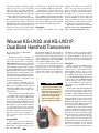
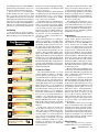
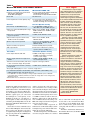
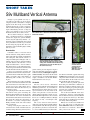
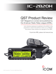
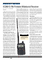
PRODUCT REVIEW ICOM IC-R6 Portable Wideband Receiver Reviewed by Steve Ford, WB8IMY QST Editor My very first receiver, the one that introduced me to the strange noises being generated by people who called themselves “hams,” was a monster. The Hallicrafters S-40B was a hulking black box that tipped the scales at something in excess of 25 pounds. Fast forward 40 years and the breakneck evolution of technology has turned the S-40B and radios like it into little more than beloved curiosities. Over the years we’ve seen radios become ever smaller thanks to astonishing progress in semiconductor technology combined with ultra-miniature surface-mount components. The new ICOM IC-R6 portable receiver is an example of how far we’ve come. My S-40B has effectively shrunk to a pocket sized box that weighs less than 8 ounces. Moreover, its frequency coverage has expanded from the depths of longwave to the rarified atmosphere of microwaves. And then there are the IC-R6 memories, multiple scanning functions and … well, at least the S-40B still retains its nostalgia value! Tiny Package, Large Feature Set frequencies by MHz to speed the process. From a convenience standpoint, it’s fortunate that the IC-R6 is loaded with memory channels — more than 1300 of them. It is easier to flip through these channels, which can also be organized by band or activity, than it is to rely on VFO tuning. The radio arrives with weather, marine and a slew of shortwave broadcast frequencies preprogrammed. You can populate the remaining memory slots in several ways. One method is to manually dial up your desired frequency and write it to memory. You can add an alphanumeric tag for easy reference later. Another approach is to allow the IC-R6 to scan a given frequency range and automatically fill the memory channels with any signals it finds. The IC-R6 offers extremely fast scanning, on the order of 100 channels per second. My preference was to invest in the ICOM OPC-478UC USB “cloning cable” and do the memory programming from my laptop computer. This turned out to be the easiest method by far. Using the ICOM CS-R6 software for Windows (Figure 1), I was able to The ICOM IC-R6 is a wideband AM and FM receiver that covers 100 kHz to 1300 MHz (cellular telephone frequencies blocked, of course). At first glance it looks like a handheld transceiver complete with a rubberized PTT button on the side. That actually serves as the FUNCTION and SQUELCH/MONITOR switches. The antenna connector is a female SMA; it sits next to an earphone jack that doubles as the data port. The knob on top is normally used to change frequencies or memory channels. UP and DOWN buttons on the front panel control the audio volume, although you can use the IC-R6 menu options to switch the volume adjustments to the knob and assign frequency tuning to the UP/DOWN buttons. The IC-R6 offers a variable frequency oscillator (VFO) tuning function, but this works best when you’re navigating a limited range of spectrum within a given band. There is no way to easily enter a specific frequency directly. Instead, you must first navigate to the desired band, then twist the VFO knob until you see the desired frequency on the liquid crystal display (LCD) — you can step Mark J. Wilson, K1RO 48 November 2010 Bottom Line Product Review Editor Power Options The IC-R6 is supplied with two AA size NiMH rechargeable batteries and a small wall charger. If you wish, you can swap the rechargeable cells for AA alkaline batteries, but I found that the NiMH cells provided plenty of listening time. When it comes to charging batteries in the IC-R6, it is important to read the manual. If the batteries are being charged for the first time, or if you’ve removed the batteries for longer than two seconds, you have to go through a multi-step process to place the receiver in the charging mode. I skipped this page in the manual and found myself frustrated with what I thought was a defective charger! It is worth noting that there is a drop-in charger option for the IC-R6 — the ICOM BC-194. However, I didn’t have the unit to test for this review. Surfing the Ether with the IC-R6 One of the first things I discovered about the IC-R6 didn’t come as a surprise. The radio is supplied with a 6 inch flexible rubber antenna. This antenna is fine for local VHF/UHF signals, but woefully inadequate for shortwave listening. If you confine yourself to the stock antenna, you may hear a few of the louder shortwave broadcasters, but not much more. Adding a longer antenna makes a world of difference. I had a 4 foot telescoping whip antenna that I attached to the IC-R6 by way of a connector adapter to go from the whip’s BNC connector to the radio’s SMA connector. Such adapters are available from many dealers. Alternatively, you can use the IC-R6 option menus to switch the external antenna from the SMA jack to the earphone cable. That’s right; the IC-R6 has the ability to turn your earphone or headphone cord into an antenna. If you don’t have a longer antenna at hand, this option is vastly superior to the flexible antenna for shortwave listening. The IC-R6 portable wideband receiver packs a lot of performance into a tiny package. read the contents of the receiver’s memory, modify the contents (or add new frequencies) and then write everything back to the radio. You can organize the entire memory array any way you desire, add alphanumeric channel labels, select tone squelch frequencies and designate particular channels to be skipped while scanning. [email protected] Be warned that if you take the antenna possibilities to their logical conclusions and connect the IC-R6 to something much bigger, such as an HF dipole antenna, you’ll be treated to horrendous overload. Fortunately, the IC-R6 has an attenuator option that goes a long way toward reducing the cacophony. Speaking of antennas, I was pleasantly surprised to discover that the IC-R6 features an internal ferrite bar antenna for AM broadcast listening. That is something you don’t find often in receivers of this type. It isn’t a large ferrite, but it made a substantial difference in AM broadcast listening. Once the radio was fully programmed, listening was pure pleasure. I was eavesdropping on everything from air traffic control to local police and fire, to railroad chatter and, of course, shortwave broadcast. The receiver’s triple conversion design is remarkably sensitive. With the IC-R6 connected to my 2 meter mobile antenna, I enjoyed listening to Radio Bulgaria and the BBC on my way to and from the office. The speaker in the IC-R6 is about an inch in diameter, so audio fidelity is mediocre at best, especially when you have to crank up the volume to overcome local distractions. The IC-R6 listening experience is much better with headphones, even though the design provides audio in one ear only. It doesn’t have to be stereo, but having audio in both earpieces of typical stereo headphones would have been nice. [A simple adapter could be fabricated to solve that problem. — Ed.] I had only one minor nit to pick with this radio, one that will probably bother few other listeners. If you’re cruising the longwave frequencies (153 to 269 kHz), you quickly discover that the IC-R6 does not allow you to tune in 1 kHz steps. This is a problem because frequency tuning is critical and most longwave stations broadcast on odd-numbered frequencies such as 153 or 161 kHz. Without the ability to tune in 1 kHz steps, you can’t zero in on the correct frequencies. The only solution I found was to set up the frequencies in software and write them to dedicated longwave memory channels. Table 1 ICOM IC-R6, serial number 16001018 Manufacturer’s Specifications Measured in the ARRL Lab Frequency coverage: 0.01-821.995, 0.01-823.995, 849-868.995, 851-866.995, 896-1309.995 MHz. 894-1309.995 MHz. Modes of operation: AM, FM, WFM As specified. Power requirement: 130 mA (rated audio), 124 mA (max audio, no signal, lights on), 65 mA (standby), 30 mA (power save) 61 mA (standby), 20 mA (power save) at 3 V dc. at 3 V dc. AM sensitivity: 10 dB S/N; 1 kHz tone, 10 dB (S+N)/N, 1-kHz, 30% modulation: 30% modulation: 0.150 MHz, 3.12 µV; 0.205 MHz, 1.78 µV; 0.495-4.995 MHz, 1.3 µV; 0.290 MHz, 1.30 µV; 0.530 MHz, 1.16 µV; 5.0-29.995 MHz, 0.89 µV; 118-136 MHz, 1.710 MHz, 0.93 µV; 3.300 MHz, 0.68 µV; 0.63 µV; 222.0-246.995 MHz, 0.63 µV; 7.350 MHz, 0.71 µV; 11.875 MHz, 0.59 µV; 247.0-329.995 MHz, 0.63 µV. 15.315 MHz, 0.69 µV; 21.650 MHz, 0.65 µV; 25.885 MHz, 0.59 µV; 50.4 MHz, 0.5 µV 120.0 MHz, 0.52 µV; 366.0 MHz, 0.48 µV. FM sensitivity, for 12 dB SINAD: For 12 dB SINAD: 1 kHz tone, 3 kHz deviation: 1.625-4.995 MHz, 0.32 µV; 29.0 MHz, 0.18 µV; 40.0 MHz, 0.15 µV; 5.0-29.995 MHz, 0.25 µV; 52.0 MHz, 0.15 µV; 72.0 MHz, 0.15 µV; 30.0-469.995 MHz, 0.18 µV; 146.0 MHz, 0.18 µV; 162.5 MHz, 0.17 µV; 470.000-832.995 MHz, 0.32 µV; 223.0 MHz, 0.15 µV; 440.0 MHz, 0.16 µV; 833.0-1029.995 MHz, 0.28 µV; 465.0 MHz, 0.16 µV; 800.0 MHz, 0.32 µV; 1030.995-1309.995 MHz, 0.35 µV. 902.0 MHz, 0.24 µV; 1280.0 MHz, 0.14 µV. WFM sensitivity, for 12 dB SINAD: For 12 dB SINAD: 1 kHz tone, 50 kHz deviation; 76.000-108.000 MHz, 1.1 µV, 88.1 MHz, 1.00 µV; 98.1 MHz, 1.05 µV; 175.000-221.995 MHz, 1.1 µV; 107.9 MHz, 1.03 µV; 200.0 MHz, 1.10 µV; 470.000-770.000 MHz, 1.8 µV. 600.0 MHz, 1.61 µV. IF rejection: Not specified. 29.0 MHz, 76 dB; 52.0 MHz, 19 dB; 72.0 MHz, 19 dB; 146.0 MHz, 82 dB; 223.0 MHz, 22 dB; 440.0 MHz, 63 dB; 902.0 MHz, 84 dB; 1280.0 MHz, >133 dB. Image rejection: Not specified. 29.0 MHz, 64 dB; 52.0 MHz, 52 dB; 72.0 MHz, 74 dB; 146.0 MHz, 76 dB; 223.0 MHz, 51 dB; 440.0 MHz, 82 dB; 902.0 MHz, 77 dB; 1280.0 MHz, >133 dB. FM adjacent channel rejection: 20 kHz offset, 29 MHz, 47 dB; 52 MHz, 52 dB; Not specified. 146 MHz, 46 dB; 223 MHz, 47 dB; 440 MHz, 49 dB; 902 MHz, 46 dB; 1280 MHz, 46 dB. FM two-tone third order dynamic range: 20 kHz offset, 29 MHz, 71 dB*; 52 MHz, 71 dB*; Not specified. 146 MHz, 74 dB*; 223 MHz, 76 dB*; 440 MHz, 73 dB*; 902 MHz, 72 dB*; 1280 MHz, 77 dB*. 10 MHz offset, 29 MHz, 106 dB; 52 MHz, 72 dB; 146 MHz, 78 dB; 223 MHz, 75 dB; 440 MHz, 74 dB; 902 MHz, 81 dB; 1280 MHz, 93 dB. Squelch sensitivity: Not specified. 29 MHz, 0.34 µV; 52 MHz, 0.34 µV, 146 MHz, 0.38 µV; 223 MHz, 0.36 µV; 440 MHz, 0.30 µV, 902 MHz, 0.66 µV; 1280 MHz, 1.08 µV. IF/audio response: Not specified. Range at –6 dB points, AM: 128-5190 Hz. Audio output power: 80 mW typical into 8 W external speaker at 10% THD. 75 mW at 8.5% THD. Size (height, width, depth): 4 × 2.3 × 1.3 inches; weight, 7.1 oz. Price: IC-R6, $200; CS-R6 Windows programming software, $50; OPC-478UC USB cable and Windows drivers, $60; BC-194 charger stand, $35. *Measurement was noise limited at the value indicated. A Handy Handheld The ICOM IC-R6 packs an awful lot of performance into a minuscule package. I found that it was also very convenient for hunting down spurious signal sources around the house; it might be a good foxhunting receiver as well. With its extreme portability, the IC-R6 is the kind of receiver you can just drop into your pocket whenever you head out the door. Manufacturer: ICOM America, 2380 116th Ave NE, Bellevue, WA 98004; tel 800-872-4266; www.icomamerica.com. Figure 1 — The ICOM CS-R6 software for the IC-R6. November 2010 49 Hamtronics R303-137 Weather Satellite Receiver Board Reviewed by Mark Spencer, WA8SME ARRL Educational and Technology Program Coordinator I have been a user of the NOAA polar orbiting satellites sending automatic picture transmission or APT imagery for years. Additionally, during the ARRL Teachers Institutes, I encourage teachers to use these NOAA satellite signals and their imagery in their classrooms. A number of TI graduates have installed satellite ground stations at their schools and share imagery and weather observations across the county. For hams interested in exploring the satellite facet of the hobby, the NOAA satellites are an excellent resource because their VHF signals at 137 MHz are relatively strong. They are easy to receive with basic equipment, and a variety of computer software packages (many freely available) make the display of the imagery from space a snap. The typical received image is illustrated in Figure 2, which was produced during this review. Though you can receive the NOAA signals with a regular 2 meter FM radio or police scanner tuned to the 137 MHz channels, quality reception of the APT signals requires a wider receiver bandwidth than FM voice. A receiver designed for APT reception gives far better results. Overview The Hamtronics R303-137 receiver is a replacement for the successful R139 weather satellite receiver that I have used for many years. It’s is a weather satellite adaptation of the Hamtronics commercialgrade VHF FM receiver. The R303-137 has four frequency synthesized channels that cover the NOAA satellite frequency plan and it has an IF bandwidth that is optimized to receive APT imagery. The receiver is not a plug-and-play unit and comes as a circuit board only. The user installs and solders interconnecting cables and wires to connect the board to a 12 V power source, antenna, speaker and computer sound card. (You can mount it in a suitable enclosure if desired, but that’s not necessary.) Putting the receiver on the air re1The eight element Yagi antenna is detailed online at www.arrl.org/ariss-trackinginterface. Though the dimensions are for 2 meters, the antenna is easily scalable for 137 MHz. Contact WA8SME at mspencer@ arrl.org if you would like the dimensions for the weather satellite version of the antenna. 50 November 2010 quires only basic soldering skills and would be a good first project for those interested in hands-on construction. The Review Setup I tested the receiver using two antenna systems. The first was a high end antenna system that consists of a homemade eight element, right hand circularly polarized Yagi with an antenna mounted preamp and low loss hardline coax from the antenna to the shack.1 The antenna is mounted on a computer controlled azimuth/elevation (az/el) rotator system that automatically tracks the satellite. This antenna system has been developed over the years and gives consistent horizon to horizon, noise free imagery. The second antenna was a starter system that consisted of a homemade turnstile antenna with a run of 75 feet of RG-8X coax with and without an antenna mounted preamp.2 The display software was WXTOIMG running on a typical laptop computer.3 tional power supply cube and a few pages of documentation. The documentation, though it appears Spartan, is well written and contains all the information you need to set up and connect the receiver to the external parts required for operation. Following the directions, it doesn’t take long to solder the required wires to the through hole solder pads and make connections to the power supply, speaker, computer sound card and antenna. Channel selection is made by jumper- From the Box to First Image The review receiver came with the op2The documentation refers to the turnstile antenna design as published in the ARRL Weather Satellite Handbook (unfortunately this excellent resource is no longer in print). If you would like the details of the turnstile antenna referenced and used in this review, contact WA8SME at [email protected] and request an extract that includes the information. 3The display software used in the review can be downloaded from www.wxtoimg.com. Bottom Line With a little work, the R303-137 weather satellite receiver board offers a great way to receive fascinating weather satellite images. Figure 2 — This image was received with the R303-137 connected to a Yagi antenna and mast mounted preamp. QS1011-ProdRev03 Figure 3 — Image received using a simple turnstile antenna with no preamp. Note how noise bars in the image correlate with nulls in the antenna pattern. Table 2 Hamtronics R303-137 Weather Satellite Receiver Manufacturer’s Specifications Measured in the ARRL Lab Frequency coverage: 137.9125, 137.620, 137.100, 137.500 MHz. As specified. Power requirement: 13.6 V dc at 38-100 mA. Full volume, no signal, 90 mA. Minimum operating voltage: Not specified. 6.9 V dc. Mode of operation: FM. As specified. FM sensitivity: 0.2 µV. For 12 dB SINAD, 9 kHz deviation: 137.100 MHz, 0.27 µV; 137.5-137.9125 MHz, 0.23 µV. FM adjacent channel rejection: Not specified. 100 kHz offset, 46 dB. FM two-tone, third-order IMD dynamic range: Not specified. 100 kHz offset, 46 dB.* Squelch sensitivity: 0.15 µV. 137.5 MHz, 0.12 µV. Speaker audio output: 1 W, 8 W load. Full volume, 926 mW at 7.6% THD. THD at 1 Vrms, 2.1%. Size (width, depth): 4.0 × 1.5 inches; weight, 3 ounces. Price: R303-137 PC board, $229; ac adapter, $9.50, LNK-137 preamp, $99. *Measurement was noise limited at the value indicated. ing the appropriate pads to ground. The documentation suggests using a rotary wafer switch connected to the frequency select pads through 1N914 or similar switching diodes. During my satellite operations, I use only the newest birds (N19 and N18) of the constellation, requiring only two frequencies. Therefore an SPDT switch is all that’s required. The receiver SQUELCH and VOLUME controls are mounted on the circuit board and there is no scan function. This may seem like a limitation, but in reality it is not. In practice, the only time I listen to the audio during a satellite pass is while I am giving a demonstration; otherwise the speaker is switched out or the volume turned down so that it is not audible. Likewise, since I am not monitoring the satellite audio, I leave the squelch wide open. Finally, there are times when multiple satellites are within range at the same time, so a scan function might cause the receiver to lock on the wrong satellite. Consequently, on my R139, which does have a scan function, I leave the scan off and manually select the desired frequency. Once wired up, I connected the R303137 to the antenna and waited for the first pass. The receiver worked the first time and the results were identical to those obtained with my old R139 receiver as illustrated in Figure 2. Throughout the day I jumpered the frequency selection pads to the other three channels and captured similar results from the other birds. The only surprise was that the audio out of the COMPUTER INTERFACE port, E1, was at too high a level to be controlled by the Windows sound card control panel. The receiver produced more than adequate audio to drive the speaker and the squelch functioned as advertised. Next I connected the receiver to the temporary turnstile antenna. The receiver produced acceptable results, consistent with the limitations of the antenna, as illustrated Figure 4 — Schematic of the pad used to reduce the receiver audio output for better compatibility with computer sound cards. in Figure 3. I modeled the turnstile and displayed the elevation plot (rotated 90°) next to the imagery. There is remarkable correlation between the nulls of the antenna and the bars of noise in the image. I inserted an antenna mounted preamp, but there was little improvement in the image quality. The preamp may help with coax line loss, but it does little to make up for marginal antenna performance. There is ample sensitivity in the R303-137 to compensate for reasonable coax line losses. The simple turnstile antenna offers respectable results and I know of schools that produce excellent quality images with these fixed antennas (though it takes some tweaking to optimize the installation). I Wish They Had... In working with the R303-137 receiver, I found a few things that would improve the product. The documentation mentions that the power cube positive and negative leads are identified by ribbing on the positive lead (both leads are white). These ribs are a bit subtle and could be easily missed. If the power leads happen to be connected backward, the receiver will not work and there is a good possibility that the audio amplifier IC will be damaged by the reversed voltage. I wish that there were a protective diode installed in the positive voltage line to prevent damage. The through hole pads used to make off board connections are well marked and easy to get to. There is, however, a lack of convenient and easily identifiable ground pads for completing the interconnections. I wish that there were ground through hole pads right next to the off board connection pads to make ground returns more convenient. The documentation addresses two ways to feed the audio from the receiver to the computer sound card — connecting to the speaker audio output line, or connecting to a dedicated audio line that samples the audio before the audio output IC. The audio November 2010 51 level to the computer is critical for quality imagery. If you elect to use the speaker audio, any change in speaker volume will affect the imagery. Therefore I prefer to use a dedicated computer audio connection that is independent of the speaker volume. The output level of the dedicated audio line, however, is fixed and at too high a level to be handled by the Windows sound card VOLUME control. The voltage divider circuit depicted in Figure 4 was inserted between the E1 pad on the receiver board and the computer sound card. I wish the receiver provided a way to adjust the audio output for the computer sound card connection. The antenna connector mounted on the receiver board is a phono jack, I would prefer a more traditional coax connector such as a BNC jack. The phono jack works, but I found that the plugs that I had on hand in the shack would not seat all the way into the connector. Hamtronics sells an optional phono plug that probably fits just fine. Conclusion The last of the NOAA series of APT satellites was launched a few months ago (N19). Once the existing four birds go silent, we will lose a wonderful resource. However, I estimate that the birds will last for another 12 to 15 years, so any investment in accessing these birds is well worth the effort. The R303-137 receiver works well and is a good choice. In my view, not being plug-and-play is a plus and will encourage the development of construction skills. Manufacturer: Hamtronics, Inc, 65 Moul Rd, Hilton, NY 14468; www.hamtronics. com; e-mail [email protected]. Wouxun KG-UV2D and KG-UVD1P Dual Band Handheld Transceivers Reviewed by Bob Allison, WB1GCM ARRL Test Engineer Wouxun (pronounced, “Oh Sheng”), is a new name on the market. Undoubtedly, many radio amateurs have seen Chinese VHF/UHF handheld transceivers offered via on-line auction services directly from China with a temptingly low price. However tempting, these handheld transceivers transmitted throughout their entire frequency range and lacked basic FCC certification for use in the USA. Wouxun was granted FCC certification for the KG-UVD1P under Part 90 rules for commercial radios, clearing the way for use in the amateur bands. In this review, we will look at the per formance of Wouxun’s KG-UVD1P and KG-UV2D, and ARRL General Counsel Chris Imlay, W3KD, will clear up misconceptions about the use of these radios in the amateur bands. Over the summer I tested the KG-UVD1P at the ARRL Lab and had completed my review when, to my surprise, the KG-UV2D was released to the market. Wouxun’s US distributor, Ed Griffin, W4KMA, informed me that the KG-UV2D is identical to the KG-UVD1P, except for a slightly different case and an improvement to one of the display functions. I got the new model, and Lab test results showed identical performance. This review covers the 2 meter/70 cm version. A 2 meter/1.25 meter version is available as well. Out of the Box After a successful day instructing kit builders at ARRL Expo at the 2010 Dayton Hamvention®, I eagerly checked out the 52 November 2010 KG-UVD1P handheld I had purchased. Inside the box, I found the radio, flexible antenna, battery pack, hand strap, belt clip and a drop-in battery charger. The radio shipped with a charged battery, and soon I heard the locals chatting about the day’s events. As always, read the manual first. You’ll need some time to understand what the manual is trying to say, as the Chinese to English translation is at times puzzling and at other times amusing. For example, the transceiver has two receive frequencies, Bottom Line Wouxun has produced a fully functional dual band handheld transceiver for a lower than usual price. The KG-UV2D has its quirks and as long as the user purchases the programming cable and software, it should provide trouble-free operation. the “Master” frequency (channel A) and the “Vice” frequency (channel B). Needless to say, Wouxun’s English is a lot better than my Chinese. The manual includes a useful Shortcut Operation Sheet for 30 functions. Look Over Unlike most current handheld transceivers, the Wouxun uses a female SMA connector on the 7 inch flexible antenna, which tightens snugly to the top of the body (adapters for other connector types are available). To the right of the antenna is a very bright LED flashlight. Next in line are the rotary encoder and ON/OFF/VOLUME controls. In front of the rotary controls are a green LED that lights when the squelch opens and a red LED indicating TRANSMIT. The left side features the PUSH-TO-TALK switch and two “side keys.” SIDE KEY 1 is used for momentarily turning on the dial lamp, enabling FM broadcast band reception, scanning functions and the SOS channel. SIDE KEY 2 opens the squelch for monitoring weak signals or turns on the flashlight. The right side features speaker (8 W) and mic jacks. Both jacks are used with the optional programming cable. Each side has a battery latch, and both must be pressed firmly downward to detach the battery. There is provision for operating this transceiver with an external dc supply using an optional 12 V battery eliminator. The 1 inch speaker opening on the front panel greets the user with a V shaped grille design. Below that is the A/B button to shift transmit from Channel A to B. You can listen to two frequencies at once, but both receivers are muted upon transmit so this is not a full duplex transceiver. The TDR button just below the speaker switches the receiver from single band to dual band operation. The easy to read 9⁄16 × 11⁄2 inch display is backlit automatically when you press SIDE KEY 2 or any key on the front panel and it stays illuminatred for about 4 seconds. The 16 button keypad includes the function button and shortcuts to some features. The number, # and * keys are fully functional DTMF keys; odd tones are emitted through the speaker if other keys are pressed during transmission. Lab Testing Lab test results are shown in Table 3. These results are for the KG-UV2D, but the KG-UVD1P I tested was virtually identical. Key Measurements Summary 0.11 0.12 0.1 SINAD 0.25 Receiver Sensitivity (12dB SINAD, µV) 86@10 MHz , 82@10 MHz 90 Rx 60 Receiver 3rd-Order Dynamic Range (dB) 69@20 kHz* , 60@20 kHz* 70 Rx 40 Receiver 3rd-Order Dynamic Range (dB) 69 ChRej 50 60 90 Adjacent Channel Rejection (dB) 136** IF 60 136** 110 IF Rejection (dB) 44** 30** Img 60 Image Rejection (dB) 110 720 800 Snd 100 Audio Output (mW) 240 T-R 250 PR052 240 50 Tx-Rx Turnaround Time (ms) Key: ** Off Scale * Measurement noise limited at value shown. 2M 70 cm There were no unexpected problems during testing, but I will note a few things I would like to see improved. While the minimum squelch threshold was 0.05 µV (good), the maximum squelch threshold was 0.15 µV — not useful to block out weak co-channel users. I’d like to see at least 5 µV maximum. I found the S meter to be virtually useless. The radio shows full scale S-meter readings with a very low level signal input, making received signal level comparisons difficult. A more useful sensitivity range would be helpful, especially if working satellites or while participating in radio direction finding activities. I’ve owned handhelds with no S meter, so I didn’t consider this to be a major drawback. The other testing issue was a rather poor ability to reject images, especially on the 70 cm band. While this isn’t a problem with the flexible antenna, images may be an issue if the radio is used with a higher gain external antenna in RF congested areas. Tests showed the KG-UV2D to be very sensitive, with respectable dynamic range figures and good IF rejection. RF output was slightly higher than specified on both bands at full charge, as was audio output from the external speaker jack. The KG-UVD1P and KG-UV2D both meet FCC requirements for spurious signal and harmonic suppression. Spectrally, the KG-UV2D tested even better than the KG-UVD1P. On the Air: It Talks! The Wouxun KG-UV2D can speak either in English or Chinese to announce pressing the key pad numbers or while programming functions, though it does not announce the specific selection made for each function. For example, if I’d like to adjust my RF output power, I press the MENU button and function select is announced. I then rotate the encoder knob around to read TXP (function 04), I then press the menu button again and power select is announced. I rotate the encoder knob to read LOW and press menu again and unfortunately, it announces enter. Still, this transceiver is useful for visually impaired hams. Buddy Brannan, KB5ELV has written, “Tips and Hints for Eyes Free Operation” of the KGUVD1P. It’s available on the Wouxun.US Web site. I made many contacts on 2 meters and 70 cm and received reports of good voice clarity and correct modulation level. Receive audio quality is very good, with plenty of extra volume to overcome background noise. An icon on the display indicates a signal is being received on the “Vice” (B) channel, eliminating confusion as to what frequency or channel is active. I noticed no unusual heating of the case during high power operations. The battery takes about 5 hours to fully charge. One feature I almost missed was a 12 V dc input jack at the base of the charging stand to charge the battery pack with an external 12 V supply, such as a car battery, if needed. During three days of normal use, the batteries held up very well. I cannot call this device a battery hog. The lightweight polycarbonate case is very comfortable to use. I made it a point to use the KG-UVD1P nearly every day for a period of two months. While long-term reliability is still unknown, my initial impression is that with care, durability problems shouldn’t be encountered. Programming The slightly older KG-UVD1P has three display modes, but the nomenclature is confusing. For example, frequency mode is called VFO mode on other VHF FM transceivers. Channel mode is normally called memory mode. Function #21 selects the working mode (display mode), which selects frequency mode, channel mode and name display mode. While the user can quickly toggle between frequency and channel mode by pressing MENU + TDR, Function 21 must be used to get back into the name display mode. The KG-UV2D solved this issue by allowing the MENU + TDR toggle to change the display from frequency to channel mode with name included in the display, a much needed improvement. My first attempt at programming channel memories into the KG-UVD1P resulted in frustration. Manually programming this radio is cumbersome and not intuitive, but can be done with practice. My advice is to purchase the optional USB programming cable. The instructions that came with the programming cable were clearly written and included the necessary information to download USB drivers and programming software. There are several USB driver choices. Although Wouxun. US suggested the Prolific driver for my Windows XP system, I could not get that one to work so I tried the Wouxun driver, which worked the first time. You can also download a program called FindComPort (you need to assign a port number before programming). The Wouxun software is easy to use but basic. I soon had most of the 128 available channels programmed and named. Channel numbers are announced while in either the channel or name display modes. I programmed my favorite repeaters and simplex frequencies in channels 1 to 5. I found that I could change memory channels without looking at the radio while driving. Other Features Other popular and more expensive handheld transceivers are packed with use November 2010 53 Table 3 Wouxun KG-UV2D, serial number J08-8772 Manufacturer’s Specifications Measured in ARRL Lab Frequency coverage: Receive and transmit, Receive, 136.0-174.995, 350.0-470.995 MHz, 136-174 MHz; 350-470 MHz, 76-108 MHz (FM broadcast); 76-108 MHz (“FM Digital”). transmit 144.0-147.995, 420-449.995 MHz. Modes: FM. FM, FM narrow. only).† Power requirements: 7.4 V dc (battery Receive, battery power, 287 mA (max vol, no signal, lights on), 30 mA (power save); transmit, 1.43 A high, 0.77 A low (8.4 V dc). Receiver Receiver Dynamic Testing FM sensitivity: 12 dB SINAD, 0.16 µV. For 12 dB SINAD, 146 MHz, 0.11 µV; 162.4 MHz, 0.11 µV, 440 MHz, 0.12 µV. FM two-tone, third-order IMD dynamic range: 20 kHz offset: 146 MHz, 69 dB,* 440 MHz, Not specified. 60 dB*; 10 MHz offset: 146 MHz, 86 dB, 440 MHz, 82 dB. FM two-tone, second-order IMD dynamic range: Not specified. 146 MHz, 84 dB; 440 MHz, 99 dB. Adjacent-channel rejection: 25 kHz offset, 20 kHz offset: 146 MHz, 69 dB; 70 dB; 12.5 kHz offset, 60 dB. 440 MHz, 60 dB. Spurious response: Not specified. IF rejection, 146 and 440 MHz, >136 dB; image rejection, 146 MHz, 44 dB; 440 MHz, 30 dB. Squelch sensitivity: Not specified. At threshold, 0.05 µV; 0.15 µV (max). Audio output: 0.5 W. 0.72 W at 10 % THD into 8 W (external speaker). THD at 1 V RMS, 1.8%. Transmitter Transmitter Dynamic Testing Power output: VHF, 5 W, UHF 4 W. 146 MHz, 5.2 W (high), 1.3 W (low); 440 MHz, 4.3 W (high), 1.4 W (low) at 8.4 V dc (full charge). Spurious signal and harmonic suppression: 146 MHz, >70 dB; 440 MHz, >70 dB, >60 dB. meets FCC requirements. Transmit-receive turnaround time (PTT release Squelch on, S9 signal, 240 ms. to 50% of full audio output): Not specified. Receive-transmit turnaround time (“tx delay”): 146 MHz, 30 ms; 440 MHz, 50 ms. Not specified. Size (height, width, depth): 4.1 × 2.3 × 1.5 inches, weight, 8.8 oz. Price: KG-UV2D (146/440 or 146/222 MHz), $107. KG-UVD1P (146/440 MHz), $107. USB programming cable, $18; speaker mic, $14. †7.4 V, 1300 mAh Li-ion battery and drop-in charger supplied. Available options: 1700 mAh Li-ion battery, $24; 12 V battery eliminator, $12; dual slot charger, $24; 12 V car charger, $10; AA battery pack, $8. *Measurement was noise limited at the value indicated. ful functions. While the KG-UV2D is not nearly as sophisticated, it does have a few useful added features. The LED flashlight, for example, is very effective. While effective, the flashlight is not always functional. With the squelch open, you cannot turn the flashlight on. Consequently, if the flashlight is already on, you must have a closed squelch to shut it off. Strange, but considering the flashlight button is also the momentary SQUELCH OPEN button, I’m not surprised. Both radios include an FM broadcast tuner. Called “FM Digital” in the manual, the tuner is analog only. Frequency selection is accomplished by turning the encoding knob or by pressing either the UP or DOWN button. 54 November 2010 Audio is clear but some of the strongest stations overload the receiver, causing crackles in the sound. Reorienting the antenna reduces this unwanted effect. It appears that in China, the FM broadcast band is 76 to 108 MHz. I was reminded of this regularly since it reverts to 78 MHz each time the radio is turned on. While it’s cumbersome to crank the knob to reach our FM broadcast band starting at 88 MHz, I’m still pleased that this inexpensive transceiver has this feature. Other features include a stopwatch, an SOS function, a VOX and the ability to switch from high to low power and back while transmitting by pressing the TDR button. It is interesting to have a handheld transceiver that can speak Chinese. I’ve learned Is It Legal? The FCC doesn’t require equipment authorization for any “Amateur Radio” transmitter to be operated under Part 97, except those that incorporate scanning receivers, which require a grant of certification. If an Amateur Radio transmitter also includes frequencies allocated to other services, and if the device is intended to operate in those other services as well as the Amateur Service, then the transmitter must be certified for all non-Part 97 radio services for which it is intended to operate. The FCC uses the term “intended to operate” as being equivalent to “capable of operation.” Wouxun is able to legally market a device that operates in the bands specified and that has a scanning receiver, because it has a certification grant (for Part 90 operation) which satisfies the certification requirement with respect to the scanning receiver. It can be operated by Part 97 licensees and by Part 90 licensees in their respective frequency bands. Wouxun US chooses to limit the frequency range of the amateur version of the device to ham bands only. Restricting the frequency range of the device to ham bands only is okay as a Class I permissive change (without recertification) as long as the means for restricting the frequency range in the amateur version of the device is not done with hardware changes and without any denigration of the characteristics of the device as reported to the FCC. Wouxun US presumably wants to make sure that Part 97 licensees do not operate the device on Part 90 channels, and vice-versa. It is good practice for them to market the ham band only version to hams, and to market the Part 90 band only version to Part 90 licensees. Good fences make good neighbors. — Chris Imlay, W3KD, ARRL General Counsel how to count from zero through nine and words such as enter and function. Most of the time, I use the English mode and I have to admit, I have grown fond of the young lady with the Chinese accent inside my radio. Distributor: Wouxun.US, PO Box 451, New London, NC 28127; tel 704-463-5820; www.wouxun.us. SHORT TAKES S9v Multiband Vertical Antenna Change is good, painful as it may occasionally be. Recently my local electric company decided to undertake a sweeping upgrade of the lines along our street. This entailed replacing the ac drop to our house with a new line arriving from a very different angle. Unfortunately, the new ac drop was going to pass entirely too close to my short inverted L antenna. It was time to move. The fact that I’m living on a tiny bit of land — and that I’m married to a wonderful woman who, despite her general affability, doesn’t enjoy the sight of my antennas — reduced my options considerably. After a quick survey, I decided it was time to go vertical in the trees along the properly line. To accomplish this I needed something light, stealthy and easy to erect. The S9v arrives as a 45 inch collapsed fiberglass tube assembly. The radiator wire is drawn into the bottom of the tube as you extend the sections. Enter the S9v I decided to order a 31 foot S9v vertical from S9 Antennas. Along with the antenna, I also ordered the S9 portable ground mount and radial plate. The antenna arrived as a collapsed multisegment fiberglass tube assembly only 45 inches in length. Dangling out of the bottom of the tube was a 31 foot length of insulated wire — the S9v radiator. The antenna doesn’t come with instructions, so before I got started I had to download and print the manual from the S9 Web site. I chose a spot among the vegetation and pounded the mount into the rocky Connecticut soil. The mount is little more than a spike within a steel tube. After a few minutes of hammering with a mallet, it was securely in place. The antenna telescopes easily. You simply pull each section forward and then twist and lock. A stainless steel screw makes sure each section stays in place. The radiator wire is drawn into the tube from the bottom as you extend the sections. Deploying the S9v took all of 15 minutes and with its forest green camouflage the fiberglass tube blended perfectly among the leaves. With the last section extended and locked, I lowered the antenna onto the mount. The mount fits snugly into the bottom of the antenna — no screws or clamps needed. Finally, I fished out the end of the radiator wire as instructed. Cutting and laying the radial wires involved an hour’s worth of work. I had to be careful to arrange them away from my wife’s The S9 radial plate. The antenna fits over the mount and rests on the saddle clamp (also available from S9 Antennas). The antenna can also rest directly on the soil if necessary. garden and her precious Japanese maple. I used some nifty little radial staples available from Ross-Radio (radialstaple.wordpress. com/ross-radio/). You stretch out the radials on top of the grass, secure them with the Ross staples, and within a few months Mother Nature buries the wires for you. On the Air The S9v can be used as a monoband 40 meter antenna without a tuner, but I wanted multiband performance. So, I installed an RF-sensing remote antenna tuner in a weatherproof enclosure at the base. Back at the station, I was pleased to see that the tuner quickly found an impedance match on every band from 40 through 6 meters. It even tuned the S9v to a 1:1 SWR on 80 meters, although the antenna is only 1⁄8 wavelength at that frequency. The “secret” of the S9v is that it is basically a wire vertical antenna with the radiator enclosed within a tube. The tube provides support (otherwise you’d have to attach the wire to a 31 foot tall tree branch) as well as insula- Steve Ford, WB8IMY 60 November 2010 QST Editor Thirty-one feet of vertical antenna soaring into the branches. It is difficult to see, but that’s the idea! tion. The S9v is flexible, capable of surviving 40 MPH sustained winds. If you’re expecting a big storm with near-hurricane force blasts, the antenna slides off the mount in seconds. You just lift the tube and lay it down. The S9v seemed to perform quite well. Even with poor summertime conditions on 40 meters, I worked a Serbian station as my first contact. Others gave good signal reports and some were astonished to learn that I was using a vertical antenna. One of the best hallmarks of the S9v’s “performance,” however, occurred when my wife strolled into the back yard and asked if I had “set up the new antenna yet.” She didn’t realize that she was standing just 15 feet from it. I merely smiled and pointed. Manufacturer: S9 Antennas, PO Box 524, Royse City, TX 75189; tel 469-426-8554; www.s9antennas.com. $89.95. Radial plate with stainless steel hardware; $24.95. Portable ground mount; $21.95. [email protected]