1
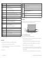
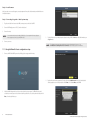
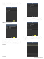
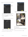
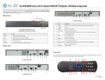
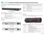
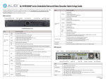
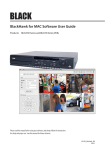
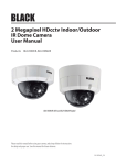
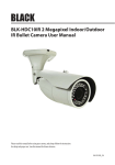
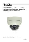
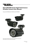
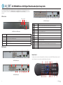
ALI-DVR3000H Series 960H Digital Video Recorder Quick Setup Guide
This quick setup guide provides instructions to initially setup and use your new digital video recorder. For additional information on the
extensive capabilities of your DVR, refer to the ALI-DVR3000H Series 960H Digital Video Recorder User Manual provided on CD with
your system.
1
2
3
4
DVR Front Panel
Status
5
TX / RX
Power LED
USB Interface
9
10
Item
Description
VIDEO IN
BNC connectors for camera video channels in. Number of channels is dependent on the model of the DVR.
2
Monitor Out (CVBS)
BNC connector for CVBS video monitor.
11
12
3
AUDIO IN
RCA connector for audio in cable.
4
ON / OFF switch
Switch for powering the DVR on and off
5
USB
This port can be used for a USB mouse or USB memory device such as a flash drive or DVD burner. An additional USB port is located on
the front panel.
Usage
Power LED
Indicator turns green when DVR is powered up.
6
HDMI
Connector HDMI monitor cable.
Status
STATUS indicator lights in red when HDD is reading/writing.
7
VGA
Connector VGA monitor cable.
TX / RX
LED indicator blinks green when network connection is functioning properly.
8
AUDIO OUT
RCA connector for audio out cable.
IR Receiver
Sensor for the remote control.
9
LAN
RJ-45 connector for Ethernet drop cable.
USB Interface
This port can be used for a USB mouse or USB flash memory devices.
DVR Backpanels
3
8
1
Item
2
7
ALI-DVR3016H backpanel
IR Receiver
ALI-DVR3000H series DVR front panel
1
6
10
RS-485 terminations
Connector for RS-485 devices. Connect the D+ and D- terminals to T+ and T- of PTZ receiver respectively.
11
12 Vdc
Plug for 12 Vdc power adapter.
12
GND terminal
Ground terminal post.
4
Remote Control
5
6
7
8
9
10
11
12
The enter key on the remote control or the front panel has the same function as a mouse left click. The IR Range of the remote control is 10
meters. The buttons on the remote control correspond with the buttons on the front panel.
ALI-DVR3004H backpanel
1
17
2
5
3
6
7
8
13
12
10 8 6
4
11 9 7
5
1
4
9
10
11
12
ALI-DVR3008H backpanel
18
1
16
15
14
3
2
ALI-DVR30xxH_SQ
1/22/14
Item
Name
Function
1
POWER
Power on/off the device.
2
DEV
Enables/Disables Remote Control.
3
Alphanumeric Buttons
Switching to the corresponding channel in Live view or PTZ Control mode.
Inputting numbers and characters in Edit mode.
Switching between different channels in All-day Playback mode.
4
EDIT Button
Editing text fields. When editing text fields, it will also function as a Backspace button to delete the character in front of the
cursor. On checkbox fields, pressing the EDIT button will tick the checkbox.
In Playback mode, it can be used to generate video clips for backup.
5
A Button
Switching between input methods (upper and lowercase alphabet, symbols and numeric input).
6
REC Button
Entering the Manual Record settings menu.
In PTZ control settings, press the REC button and then you can call a PTZ preset by pressing Numeric button.
7
PLAY Button
Playback, for direct access to playback interface.
8
INFO Button
Reserved.
9
VOIP button
Selecting all items on the list;
In live view or playback mode, it can be used to switch between main and spot video output
10
MENU button
Press the button will help you return to the Main menu (after successful login).
Press and hold the button for 5 seconds to turn off audible key beep.
11
PREV button
Switch between single screen and multi-screen mode.
12
DIRECTION/ENTER buttons
Navigating between different fields and items in menus.
In Playback mode, the UP and DOWN button are used to speed up and slow down recorded video.
The LEFT and RIGHT buttons select the next and previous day of recordings.
In LIVE view mode, these buttons can be used to cycle through channels.
13
PTZ button
Enter the PTZ Control mode.
14
ESC button
Return to the previous menu.
Press for Arming/disarming the device in Live View mode.
15
RESERVED
Reserved for future usage.
16
F1 button
Selecting all items on the list when used in a list field.
In PTZ Control mode, it will turn on/off PTZ light.
17
PTZ Control buttons
Buttons to adjust the iris, focus and zoom of a PTZ camera.
18
F2 button
Cycle through tab pages.
Action
Effect
Right click
Live view: Show menu.
Menu: Exit current menu to upper level menu.
Single click: Live view: Select channel and show the quick set menu.
Menu: Select and enter.
Left click
Scroll wheel
Double click: Live view: Switch between single-screen and multi-screen.
Click and drag: PTZ control: pan, tilt and zoom.
Tamper-proof, privacy mask and motion detection: Select target area.
Digital zoom-in: Drag and select target area.
Live view: Drag channel/time bar
Scroll up: Live view: Previous screen.
Menu: Previous item.
Scroll down: Live view: Next screen.
Menu: Next item.
Soft keyboard
An on-screen QUERTY keyboard appears when you click in a field that accepts a text entry, such as a password or name. The keyboard is
shown in the following picture. Some control keys toggle their function when they are clicked.
Symbols /
Numbers
Uppercase /
Lowercase
Backspace
Escape / Exit
Soft keyboard
Step 1. Install the DVR and monitor
For the following steps, refer to the back panel photo above for the location of connectors.
1.
Place the DVR in a location that is secure, well ventilated and clean. The DVR should be positioned such that the back panel connectors
are accessible and the ventilation holes on the sides are not blocked.
2.
Install and setup your monitor in accordance with the instructions provided with the monitor. Do not power it on at this time.
3.
Cable the HDMI or VGA connector to your monitor’s VGA or HDMI input. The HDMI interface provides the best performance.
4.
Plug the mouse into the USB connector on the front or back of the DVR.
5.
If you plan to access your DVR remotely, or configure your DVR to transmit alerts, email, etc. to external servers, plug a drop cable
from your local area network (LAN) into the RJ-45 LAN connector on the back of the DVR. (By default, the DVR automatically acquires
network settings using DHCP.)
6.
Connect the power cord to the power connector on the back panel of the DVR, and then into a UPS (preferred) or surge protector.
Mouse Control
A standard 3-button (left/right/scroll-wheel) USB mouse can also be used with this DVR. To use a USB mouse:
1.
Plug USB mouse into the either the front panel or backpanel USB connector of the DVR.
2.
The mouse will be automatically detected. If the mouse is not detected, the mouse may not be compatible with the DVR. Please refer
to the recommended device list from your provider.
The operation of the mouse:
2
www.Observint.com
© 2014 Observint Technologies, Inc. All rights reserved.
Step 2. Install cameras
Install your security cameras as needed to support your security requirements. Always refer to the documentation provided with the camera
for installation instructions.
Step 3. Connecting it together – initial system setup
1.
Plug the coaxial cables from the cameras into the BNC camera input connectors on the back of the DVR.
2.
Power on the DVR using the power on / off (I / O) switch on the back panel.
3.
Power on the monitor.
NOTE
4.
Some monitors have multiple inputs such including VGA ,HDMI, BNC, etc. If you are using this kind of monitor, configure your
monitor to display the input connected to your DVR (HDMI or VGA).
3.
The Setup Wizard can assist you in making important configuration settings in DVR. Click Next button on the Wizard window to open
the Login window.
Power on your cameras.
NOTE
The configuration settings presented in the setup Wizard can also be made and changed using the Menu system. See the
ALI-DVR3000H Series 960H Digital Video Recorder User Manual provided on CD with your system for more information.
1.1.1 Using the Wizard for basic configuration setup
1.
Power on your DVR. When the DVR is powered on, an Alibi logo splash screen appears within 2 minutes.
4.
2.
3
Enter the admin password in the appropriate field. To do that, click inside the Admin Password field to open the virtual keyboard.
Click the appropriate icons to enter the password, then click the Enter icon. The default admin password is 1111.
After the initial Alibi loading window (see above), a monitor resolution selection screen appears. The DVR will offer the optimal
resolution for your monitor, but you can select another resolution if you prefer. At this screen, select the preferred resolution, then click
Next, or allow the setup Wizard to open.
www.Observint.com
© 2014 Observint Technologies. All rights reserved.
Observint strongly recommends that you change the default admin user password to improve the security of your surveillance system.
To change the admin password, check the New Admin Password box, then enter the new password in the New Password and
Confirm fields. Record your new password and save it in a secure place for reference later.
Generally, it is preferable to setup the DVR with a fixed network settings, if possible, to assure the DVR has an unchanging IP address
for remote logins. To enable fixed network settings, uncheck the Enable DHCP box, then edit the appropriate fields to change the
settings. Consult with your network administrator to determine the best network settings for your DVR. When finished, click Next.
5.
Click the Next button to open the date and time settings window.
8.
6.
In the date and time setup window, click the field you want to change, then use the drop-down list or setup aid to select the
appropriate values. Click Next to confirm your settings or Cancel to discard them and open the network setup Wizard window.
7.
In the Network setup Wizard window, click the field value you want to change, then use the pop-up aid to enter a new value. By
default, the DVR uses DHCP (Dynamic Host Configuration Processor) to acquire compatible (dynamic, changeable) network settings
from a network DHCP server.
4
www.Observint.com
Click Next after you configured the network parameters. The HDD management Wizard window will open. If a new DVR is shipped
with a pre-configured HDD, nothing needs to be done in this window. If you installed an HDD or replaced the HDD, select (check the
box for) the HDD, then click Init to setup the disk for the DVR. NOTE: Init will erase all data from the disk. When the initialization is
complete, click Next to continue.
© 2014 Observint Technologies. All rights reserved.
9.
In the camera setup wizard, you can initially select the recording mode for each camera attached to the camera input BNC connectors.
To use this menu:
Click here to open
the camera
graphical menu
10. Click OK when the recording mode for each camera is selected. The Wizard will close and the DVR will present the Live View display.
For more information about the Live View display, refer to the user manual.
a.
In the Camera menu shown above, open graphical menu select the camera to configure. “1” (Analog 1) identifies the camera
plugged into the camera input BNC connector 1, “2” (Analog 2) identifies the camera on BNC connector 2, etc.
b.
To configure the camera for recording, click the Start Recording box to check it, then click the bullet for either Normal
(continuous) mode recording or Motion Detection mode recording.
c.
Do one of the following:
*
To copy these recording settings to other cameras connected to the DVR, click Copy, then select the other cameras to you
want to apply the settings to.
4-channel Live View display
Step 4. Using the Menu system
*
d.
5
To configure another camera differently, open the Camera graphical menu and select the next camera to configure. Then
repeat the steps above to configure the recording mode for that camera. You can also Copy these settings to other cameras.
After configuring the recording mode for each camera, click OK to confirm your settings and close the Wizard.
www.Observint.com
After the initial setup of your DVR using the Wizard, the Menus interface enables you to refine your configuration settings and expand the
functionality of the system. To use most menus, the user must log into the DVR system, either locally or remotely, with administrative
privileges.
To open the Menu system from the Live View screen, right click anywhere in the screen, then select Menu
© 2014 Observint Technologies. All rights reserved.
Specifications
Section
Item
Video/Audio Input
Video Compression
Video Input
ALI-DVR3004H
ALI-DVR3008H
4 channels
8 channels
Video Input Interface
BNC (1.0 Vp-p, 75 Ω)
Audio Compression
G.711u
Audio Input
If ID Authentication is not disabled (see the General Settings), a login window will open. In the Login window, select a User Name with
administrative privileges, enter its password, then click OK. NOTE: A window of Menu icons will open. The default user “admin” has the
default password of “1111”.
Video/Audio Output
1 channel, RCA (2.0 Vp-p, 1 kΩ) (using the audio input)
CVBS Output
1 channel, BNC (1.0 Vp-p, 75 Ω), resolution: 704 × 480
1 channel, resolution: 1920 × 1080 × 60Hz , SXGA: 1280 × 1024 × 60Hz. 1280 × 720 × 60Hz ,
1024 × 768 × 60Hz
Video Loop Out
4 channels, BNC (1.0 Vp-p, 75 Ω)
Frame Rate
Synchronous Playback
960H / 4CIF / 2CIF @ /15 fps;
CIF / QCIF @ 30 fps
4 channels
8 channels
32 kbps ~ 3072 kbps, or user defined (max. 3072 kbps)
Stream Type
Video / Video & audio
Audio Output
1 channel RCA (linear, 1 kΩ)
Audio Bit Rate
64 kbps
Dual Stream
Supported; sub-stream: CIF / QCIF @ 30 fps
External Interface
Capacity
Up to 4TB
2, USB 2.0
1, RS-485 interface, half-duple
Power supply
Consumption
Working temperature
Working humidity
Chassis
Dimension (w × d × h)
Weight
www.Observint.com
1, RJ-45 10M/100M adaptive Ethernet
USB Interface
General
6
1 SATA interface
Network Interface
Serial Interface
16 channels
WD1 / 4CIF / 2CIF / CIF / QCIF
SATA
For additional information about using your system, refer to the ALI-DVR3000H Series 960H Digital Video Recorder User Manual
provided on CD with your system.
960H @ 8 fps;
4CIF / 2CIF @ 10 fps;
CIF / QCIF @ 30 fps
Video Bit Rate
Encoding resolution
Hard Disk
16 channels
1 channel, RCA (2.0 Vp-p, 1 kΩ)
Two-way audio input
HDMI / VGA Output
ALI-DVR3016H
H.264
1, RS-485 interface, half-duplex
12 Vdc
< 10 W
< 10 W
< 15 W
14°F ~ 131 °F (-10 °C ~ +55 °C)
10 % ~ 90 %
Standalone 1U chassis
12.4" × 9.1" × 1.8" (315 mm × 230 mm × 45 mm)
≤ 4.4 lb (≤ 2 kg) w/o hard disk and DVD-R/W
© 2014 Observint Technologies. All rights reserved.