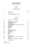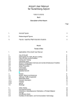
1
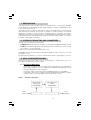
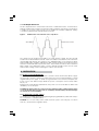
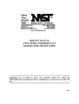
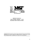
12VDC TO 230VAC INVERTERS
MODEL Nos:
CI-200 • CI-400 • CI-600 • CI-800 • CI-1000• CI-1500
OPERATION & MAINTENANCE
INSTRUCTIONS
0706
Thank you for purchasing this CLARKE Power Inverter.
Before attempting to use the Inverter, please read this manual thoroughly and follow the instructions
carefully. In doing so you will ensure the safety of yourself and that of others around you, and you
can look forward to the machine giving you long and satisfactory service.
CLARKE GUARANTEE
This CLARKE product is guaranteed against faulty manufacture for a period of 12
months from the date of purchase. Please keep your receipt as proof of purchase.
This guarantee is invalid if the product is found to have been abused or tampered
with in any way, or not used for the purpose for which it was intended.
Faulty goods should be returned to their place of purchase, no product can be
returned to us without prior permission.
This guarantee does not effect your statutory rights.
Waste electrical products should not be disposed of with household waste.
Please dispose of at your local recycling facility
Specifications
Model No
Part No
Power
CI-200 ...................................... 6013005 ................................. 100 watt
CI-400 ...................................... 6013008 ................................. 200 watt
CI-600 ...................................... 6013010 ................................. 300 watt
CI-800 ...................................... 6013015 ................................. 400 watt
CI-1000 .................................... 6013020 ................................. 500 watt
CI-1500 .................................... 6013025 ................................. 750 watt
• Output Connection: Standard Receptacles
• Output Voltage: AC (RMS)
• Output Waveform: Modified Sine Wave
• Input Voltage Range: 11 to 15 VDC
• Low Voltage Alarm: approx. 10.5 VDC
• Low Voltage Shutdown: approx.10.0 VDC
• Input Cables: Cigarette Lighter Plug (up to 150 watts) Battery Clip Cable
• Additional Protection: Overload, Over voltage, Over temp.
Please note that the details and specifications contained herein, are correct at the time of going to print. However,
CLARKE International reserve the right to change specifications at any time without prior notice.
• THERE ARE NO USER SERVICEABLE COMPONENTS WITHIN THIS PRODUCT
• THIS PRODUCT EMPLOYS MOSFET TECHNOLOGY, AND CARE MUST BE TAKEN
TO AVOID SUBJECTING COMPONENTS TO A STATIC CHARGE - WHEN
SERVICING ETC., AS THIS COULD CAUSE IRREPARABLE DAMAGE.
-2-
Safety Precautions
WARNING:
To ensure reliable service from your power inverter, you must ensure it is installed
and used according to these operator instructions, please read these instructions
thoroughly before attempting to use the inverter.
Pay particular attention to the WARNING and CAUTION statements in this manual.
CAUTION statements advise against certain conditions and practises that could result
in damage to your inverter.
WARNING statements identify conditions or practises that could result in personal
injury.
CAUTIONS
1. DO NOT use with positive earth systems (the majority of modern vehicles’s, lorries, boats
etc., are negative earth). Reverse polarity connection will result in a blown fuse and
may cause permanent damage to the inverter.
2. This inverter will not operate high wattage appliances.
3. DO NOT use if it is wet.
4. DO NOT install inside an engine compartment - inverter MUST be installed in a well
ventilated area.
5. This inverter is not tested for use with medical devices.
WARNINGS
TO REDUCE THE RISK OF FIRE, ELECTRIC SHOCK, EXPLOSION OR INJURY:
1. DO NOT connect to an AC supply.
2. Before making adjustment etc., to the appliance being run by the inverter, ALWAYS
disconnect the appliance from the inverter beforehand.
3. DO NOT make or break any electrical connections in explosive areas such as garage
forecourts etc. This applies to all types of connection including cigarette lighter type
plugs.
IMPORTANT CABLE INFORMATION
Attention must be paid to the cable used between the appliance and the inverter. It must
be of the correct diameter and length, otherwise power loss or reduced operating time
may occur.
Marine installations are also subjected to vibration and stresses that exceed those of other
mobile installations. Therefore ensure all connections are tight, water resistant and have
suitable strain relief for DC cables etc.
Cable installation must be the correct type for the environment.
-3-
1. INTRODUCTION
Your new inverter is one in a series of the most advanced DC to AC inverters available
today. With proper care and appropriate usage, it will give you years of dependable service
in your car, truck, RV or boat.
The inverter supplies continuous 230V, 50Hz power via a standard 3-pin socket whenever
and wherever it is required. The inverter is capable of running a range of household
appliances, including colour TV’s, TV/VCR combinations, laptop computers, camcorders,
cellular phone, power tool chargers, lamps etc., depending upon the rating of the converter.
Added safety features include automatic shutdown and a low battery alarm - to avoid the
possibility of damaging your battery.
2. CONTROLS. INDICATORS AND CONNECTORS
Two LED’s are provided on the front panel.
• The GREEN LED illuminates when the converter is connected, switched ON, and working correctly.
• The RED LED , when illuminated, indicates that the inverter has shutdown - from overload,
over voltage or over temperature.
230V Power is provided via a standard 3-pin socket.
An ON/OFF switch turns the inverter circuitry On and Off. The switch is used to force reset
the inverter circuits.
The back panel provides DC connectors, either battery clamps or cigar lighter connector.
3. HOW YOUR INVERTER WORKS
The inverter converts a 12V direct current - from a battery or other power source, to a
230V 50Hz AC (alternating current) output.
3.1. Principle of Operation
The inverter converts power in two stages. The first stage raises the low voltage DC
input to high voltage DC. The second stage is the actual inverter stage that converts
the high voltage DC into AC. See figure 1.
The inverter stage uses advanced power MOSFET transistors in a full bridge
configuration. This ensures excellent overload capability and the ability to operate
reactive loads such as lamp ballasts and small induction motors.
Figure 1
Principle of Operation
I2VDC TO high
voltage DC
CONVERSION
High voltage DC
TO AC
CONVERSION
To AC
Appliance
I2VDC
Input
-8-
3.2. The Output Waveform
The AC output waveform of the inverter is known as “modified sine wave”. It is a waveform
that has characteristics similar to the sine wave shape of utility power. This type of waveform
is suitable for most AC loads, but may not be suitable for scientific equipment. Always
consult the manufacturers manual where necessary.
Figure 2
Modified sine wave and sine wave comparison
Sine Wave
Modified Sine Wave
The output from this inverter has an RMS (root mean square) voltage, the same as that
found in a normal standard household - 230V. It should be noted, that most AC voltmeters
(both digital and analog) are sensitive to the AVERAGE value of the waveform rather
than the RMS value, and are calibrated for RMS voltage under the assumption that the
waveform measured will be a pure sine wave. These meters, therefore, will not read the
RMS voltage of a modified sine wave correctly, and will read about 20 to 30 volts lower
than the true voltage, when measuring the output of the inverter.
4. INSTALLATION
4.1. Power Source Requirements
The power source must provide between 11 and 15 volts DC and must be able to supply
the necessary current to operate the load. The power source may be a battery or a well
regulated DC power supply. To obtain a rough estimate of the current (in amperes) the
power source must deliver, simply divide the power consumption of the load (in watts
AC) by 10.
Example: if a load is rated at 300 watts AC, the power source must be able to deliver: 300
divided by 10 = 30 amperes
CAUTION: the inverter must, be connected only to batteries with a nominal output voltage
of 12 volts. The unit will not operate from a 6-volt battery and will sustain permanent damage
if connected to a 24-volt battery.
4.2. Connection to Power Source
The inverter is provided with a fused cigarette lighter plug and battery cables with clamps
for connection to a suitable battery:
CAUTION: Do not use with positive earth electrical systems (The majority of modern
vehicles, , and lorries are negative earth).
-5-
Connecting to source using cigarette lighter plug:
The cigarette lighter plug is suitable for operating the inverter at power outputs up to 150
watts. The tip of the plug is positive and the side contact is negative. Connect the inverter
to the power source by inserting the cigarette lighter plug firmly into the cigarette lighter
socket of a vehicle or other DC power source.
Connect directly to power source when operating above 150 Watts.
NOTE: Most vehicle cigarette lighter circuits use fuses rated at 15 to 20 Amps or greater. To
operate at full power output, either use the battery clamp cable (supplied) or directly wire
to the power source with user-supplied wire and fuse.
CAUTION: Reverse polarity connection will result in a blown fuse and may cause permanent
damage to the inverter.
Connecting to a Power Source Using Cables Connectors Provided:
If the inverter is to be used for extended periods at power levels above 150 watts, direct
connection to the power source is necessary. Use the cables provided to connect the
inverter directly to the 12 volt power source using the following guidelines:
1.
Check to be sure the inverter’s power switch is turned OFF and that no flammable
fumes are present.
2.
Connect the black cable to the black post marked “(-)” on the back of the inverter.
Connect the black battery clip to the negative terminal of the battery.
3.
Connect the red cable to the red post marked “(+)”on the back of the inverter.
Connect the red battery clip to the positive terminal of the battery.
4.
Check to ensure that all connections between battery clips and terminals are
clean and secure.
CAUTION: Loose connectors may cause overheated wires and melted insulation. Check
to make sure you have not reversed the polarity.
4.3. Connection to Load
With the inverter connected to the power source, but switched OFF, plug the cable, from
the appliance you wish to operate, into the AC receptacle on the inverter. Switch ON and
the green LED will illuminate to indicate that the inverter is functioning. Make sure the
combined load of your equipment does not exceed the rated output of the converter
(Watts).
The Inverter is engineered to be connected directly to standard electrical and electronic
equipment in the manner described above.
WARNING:
DO NOT UNDER ANY CIRCUMSTANCES connect the Inverter to household AC circuits
CAUTION: RECHARGEABLE APPLIANCES
Certain rechargeable devices are designed to be recharged by plugging them directly
into an AC receptacle. Do not use the inverter to recharge these devices as they could
damage the inverter.
This problem does not occur with the majority of battery operated equipment. Most of
these devices use a separate charger or transformer that is plugged into an AC receptacle.
The inverter is capable of running most chargers and transformers.
-6-
4.4.
Placement of the Inverter
For best operating results, the inverter should be placed on a flat level surface. 3 feet (1.0
meter) cables are provided allowing for easy positioning of the inverter. The inverter should
only be used in locations that meet the following criteria:
DRY - Do not allow water and/or other liquids to come into contact with the inverter.
COOL - Ambient air temperature should be between -1OC (30O F) and 40OC, (105OF). Do not
place the inverter on or near a heating vent or any piece of equipment which is generating
heat. Keep the inverter away from direct sunlight.
VENTILATED - Keep the area surrounding the inverter clear to ensure free air circulation
around the unit. Do not place items on or over the inverter during operation. A fan is helpful
if the inverter is operating at maximum power outputs for extended periods of time. The unit
will shut down if the internal temperature exceeds 65OC. The unit will restart after it cools.
SAFE - Do not use the inverter near flammable materials or in locations that may accumulate
flammable fumes or gases.
5. OPERATING TIPS
5.1.
Rated Versus Actual Current Draw of Equipment
Most electrical tools, appliances and audio/video equipment have labels that indicate
the power consumption in watts. Be sure that the power consumption of the appliance
you wish to operate is rated at the specified wattage, or less.
The inverter is provided with thermal overload protection. If the temperature increases to
60OC, the buzzer will sound for 1 minute, then the unit will shut down, when the temperature
reaches 65OC. It will restart once the temperature drops sufficiently. Investigate the cause
of the overload and rectify before restarting the appliance.
Resistive loads are the easiest for the inverter to run. However, larger resistive loads, such as
electric stoves or heaters, usually require more power than the inverter can deliver on a
continuous basis. Inductive loads, such as TV’s and stereos, require more current to operate
than do resistive loads of the same wattage rating. Induction motors, as well as some televisions,
may require 2 to 6 times their wattage rating to start up. The most demanding in this category
are those that start under load, such as compressors and pumps. Testing is the only definitive
way to determine whether a specific load can be started and how long it can run. The unit
will simply shut down if it is overloaded. To restart the unit after a shutdown due to overloading,
disconnect the load and if necessary turn the power switch OFF then ON.
CAUTION: This inverter will not operate high wattage appliances.
5.2.
Battery Operating Time
Battery operating time depends upon how much is drawn to operate the particular appliance.
A 120 ampere hour battery for example, can, theoretically, provide 40 amps for a period of 3
hours. However, we recommend that the battery be charged (start the engine) regularly in
order to maintain sufficient output. This will guard against any unexpected shutdown of the
equipment and will ensure that there is always sufficient battery capacity to start the vehicle’s
engine. The inverter will sound its alarm when DC voltage drops to 10.5V.
The inverter may be used whether or not the vehicle’s engine is running. However, the
inverter may not operate while the engine is starting since the battery voltage can drop
substantially during cranking.
In most instances, the inverter can be left connected to the battery when not in use since
it draws little current. However if the vehicle is to remain unused for several days, then
disconnect it from the battery.
-7-
6. PROTECTION FEATURES OF INVERTER
Your inverter monitors the following potentially hazardous conditions:
Low Battery Voltage - This condition is not harmful to the inverter but could damage the
power source. An audible alarm will sound when input voltage drops to 10.5 volts. The
inverter automatically shuts down when input voltage drops to 10.0 volts. When the
condition is rectified, the unit may be restarted.
Over Voltage Protection - The inverter will automatically shut down when the input
voltage exceeds 15 volts DC.
Short Circuit Protection - The inverter will shut down. Remove the short circuit and inverter
will auto reset.
Overload Protection - The inverter will automatically shut down when the continuous
draw exceeds the specified watts.
Thermal Overload Protection - When the temperature sensor reaches 65OC (150OF),
the unit will automatically shut down. Allow the unit to cool for at least 15 minutes before
attempting to restart. Unplug unit while cooling.
Low Battery Alarm - An alarm will sound when the voltage from the battery drops to
10.5 volts. The user should stop operation of the appliance at this time since the inverter
will shut down automatically shortly thereafter, when the battery voltage drops to 10 volts.
Start your engine to recharge the battery.
If the low voltage alarm sounds when the battery is fully charged, follow the steps for
solving lack of output power in the Troubleshooting Guide.
The alarm will sound when the inverter is overloaded, in thermal shutdown, or if there is an
excessive voltage drop between the battery and inverter.
7. COMMON PROBLEMS
“Buzzing” sound in audio systems:
Some inexpensive stereo systems and ‘boom boxes’ emit a buzzing sound from their
speakers when operated from the inverter. This occurs because the power supply in the
electronic device does not adequately filter the modified sine wave produced by the
inverter. The only solution to this problem is to use a higher quality sound system that
incorporates a higher quality power amplified supply.
Television Interference:
The inverter is shielded to minimize interference with TV signals. However, in some instances,
some interference may still be visible, particularly with weak TV signals. Try the following
corrective measures:
•
Position the inverter as far as possible from the television, the antenna and the
antenna cables. Use an extension cable, if necessary
•
Adjust the orientation of the inverter, the antenna cables and the TV power cord
to minimize interference
•
Make sure that the antenna feeding the television provides an adequate (“snow
free) signal and that high quality, shielded antenna cable is used.
-8-
8. TROUBLESHOOTING
FAULT
No AC output - red LED
illuminated
POSSIBLE CAUSE
DC input below 10Volts
Excessive load - thermal
shutdown
REMEDY
Recharge or replace battery
Reduce load - wait for
inverter to cool. Turn Off, then
turn On
No AC output
Inverter cold
Disconnect load from
inverter. Operate inverter
without load for a few
minutes. Reconnect load.
No AC output - Green LED
not illuminated
Inverter fuse blown
Remove fuses from their holders
and replace with those of the
same type and rating
Low battery alarm sounds
continuously
Bad wiring connections
Tighten all DC connections
Low battery alarm sounds
Low battery voltage
Recharge battery
Remove load from inverter
and recharge battery
Motorised power tool
won’t start
Excessive start-up load
If appliance does not start,
then appliance is drawing
excessive wattage and will
not work with inverter
Motorised power tool
does not operate at
correct speed
Purely inductive load
Make the load not purely
inductive. Operate an
incandescent lamp at same
time as motor, ensuring the
combined load does not
exceed that of the inverter.
Television/Radio
interference
Snow in picture, buzz in
speaker
Keep inverter and antenna
distant from each other. Use
shielded antenna cable.
Connect antenna to amplifier
9. FUSE REPLACEMENT
If the external fuse blows, then there is most likely a short or overload in the DC wiring. Find
and fix the problem before replacing the fuses. After fuse replacement, reconnect the
inverter, if fuse continues to blow, contact your Clarke dealer, or telephone Clarke
International on 020 8998 7400.
This power inverter is equipped with an external fuse. Normally, this fuse will not blow
unless there is a serious problem inside the unit. DO NOT open the unit, there are no user
serviceable parts inside the unit.
-9-