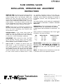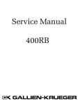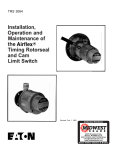
1
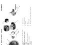
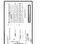
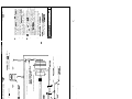
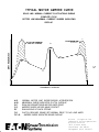
PP 3000 Warning Forward this manual to the person responsible for Installation, Operation and Maintenance of the product described herein. Without access to this information, faulty Installation, Operation or Maintenance may result in personal injury or equipment damage. Installation, Operation and Maintenance of the Airflex® FSPA Applications Caution: Use Only Genuine Airflex Replacement Parts The Airflex Division of Eaton Corporation recommends the use of genuine Airflex replacement parts. The use of non-genuine Airflex replacement parts could result in substandard product performance, and may void your Eaton warranty. For optimum performance, contact Airflex: In the U.S.A. and Canada: (800) 233-5890 Outside the U.S.A. and Canada: (216) 281-2211 February, 1981 203673 PDF Format © Copyright Eaton Corp., 1998.All rights reserved. 9. AIR TUBES 3. INNER TIMKEN BEARING CONE 3A. OUTER TIMKEN BEARING CONE 7. COMBINATION CLUTCH BRAKE DRUM 6. REACTION PIN 5. AIRFLEX CS OR CTF TYPE BRAKE 15. ROTORSEAL 14. AIR TUBES 13. ROTORSEAL ADAPTER 10. AIRFLEX TIMING ROTORSEAL 8. AIRFLEX QUICK RELEASE VALVE AVAILABLE WITH OR WITHOUT MUFFLER 2. OIL SEAL 4. AIRFLEX CB OR VC TYPE CLUTCH 7A. SEPARATE CLUTCH BRAKE DRUM 1. NEW FLYWHEEL OR BULLGEAR 9or14 FSPA EXPLODED VIEW 37. TIMlNG ROTORSEAL DRIVE SCREW 36. END PLATE 20. KEY 19. SHIMS 18. CAP SCREWS 17. END PLATE PP3003 I.OPERATION A. DESCRIPTlON B. HOW IT WORKS The Airflex FSPA is a self-contained clutch-brake package designed primarily for power press applications. The standard FSPA sizes available are ideally suited for and can be easily adapted to practically all OBI, straight-side and like presses from two ton capacity and up. It can also be used on other types of machines requiring high cyclic operation. The major components of the FSPA package are: The combination or separate clutch and brake drums are keyed to the shaft. The bearing mounted flywheel or bullgear mounts and rides on the outside diameter of the clutch drum hub. The clutch element is attached to the flywheel or bullgear. Air to engage the clutch is introduced through a timing rotorseal or standard rotorseal. The brake is attached to and reacted by the press frame. 1. Starting and stopping is accomplished by the simultaneous action of the clutch and the brake. Air to engage the clutch simultaneously releases the brake, allowing the press crankshaft to rotate. When the air pressure to the clutch and brake is exhausted, the clutch disengages rapidly and the spring applied brake is engaged, thus stopping the crankshaft. The timing rotorseal or separate timer signals the solenoid valve, which controls the air to the clutch and brake, at the proper point during crankshaft rotation. Airflex “CB” or "VC” clutch. 2. A new flywheel or bullgear with anti-friction bearings. 3. Airflex spring applied air released brake. 4. Clutch and Brake Drums 5. Airflex quick release valves. 6. Timing rotorseal or standard rotorseal. II. INSTALLATION All Airflex FSPA applications are shipped from the factory partially assembled so that a minimum amount of work is necessary for installation on the press. NOTE: One exception to this is on the small size FSPA No. L-l where a relatively small shaft diameter limits the number of mounting holes to one in the center of the shafts. See tabulation on “Dimensional Data” sheet. A. MOUNTING 2. Before inserting the key (20) into the shaft, remove all burrs or nicks from the key, keyway and shaft. The following instructions are provided to guide you through the recommended assembly sequence. Please read these instructions thoroughly prior to performing the actual work. See exploded view. 3. W ith key in p lace, coat t he shaft and key with oil, or Prefera bly with white lead and oil. Customers who rework their own shafts will require all the instructions contained herein for assembly o f t h e p a r t s . Customers who send their shafts to Airflex for machining and assembly should disregard items one through fourteen. 4. Heat the combination clutch and brake drum (7) either in oil or with a torch to approximately 275°F. It is best to heat in oil if possible; however, if a torch is used, be sure the drum and hub are heated uniformly. 1. Machine the shaft on which the FSPA unit is to be mounted according t o d i m e n s i o n s s h o w n o n “Dimensional Data” sheet. This entails turning the shaft to a specified diameter and distance from the press frame bearing as well as cutting the keyway or keyways as shown. 5. Have hydraulic press or driving bars available for driving the heated drum and hub home on the shaft. The heat transferred from the combination drum and hub to the shaft will be rather rapid which will cause the shaft to expand and possibly create interference during assembly. Because of this, it is very important to drive the drum and hub home as rapidly as possible. If the drum and hub has been heated sufficiently, it should slide on the shaft relatively easy. If separate clutch and brake drums (7A) are used, repeat steps two through five for the brake drum. NOTE: For Special bores not listed, machine the shaft diameter to provide an interference fit of approximately .0005" per inch of shaft diameter. When a timing rotorseal (10) is used, the end of the shaft must be drilled and tapped for the timing rotorseal drive screw (37). (See note 5 on “Dimensional Data” sheet.) 6. Allow time for the drum and hub to cool to room temperature. Where the standard rotorseal adapter (13) is used, two holes must be drilled and tapped in the end of the shaft 180 degrees apart to secure the end plate ( 17). 7. When the drum and hub has cooled sufficiently, install the inboard Timken Bearing Cone (3). Preheat this bearing cone in hot oil to facilitate easier assembly. -1- NOTE: Once assembled, the bearing should be “held” against the shoujder of the drum, while cooling. 13 . M.ount the component parts for air distribution to the! (zlutch’as follows: Timing Rotorseal Mounting IMPORTANT: After bearing has cooled thoroughly, hand ‘@ack it wtih grease before installing flywheel or .bullgedr. assembly. Use Mobilux # 2 or equivalent non-fibrous grease. Install the timing rotorseal drive screw (37). Tighten the screw and then tie-wire to the four end plate mounting screws. Do not distort end plate while tightening screws. 8. Install the factory-assembled unit consisting of the flywheel 01 .buIlgcear (I 1, clutch (41, oil seal (2) and outer Timken bearing.,race. When sliding the assembly into position, CARE MUST BE TAKEN so as not. to damage the oil.seal (2). - Install the timing rotorseal (10) on flywheel ( 1’) or bullgear hub.. Align the tan@ of the drive shaft with the slot in the mating drivescrew, AND SIMULTANEOUSLY ALIGN THE GREASE HOLES IN THE ADAPTER FLANGE WITH THOSE IN THE FLYWHEEL. Tighten the mounting bolts uniformly so the adapter flange will fit squarely against the register face. 9. With flywheel in position, pack flywheel cavity with grease (approximately half full) before installation of outer Timken bearing cone (3A). Next, hand pack bearing cone w5th grease and carefully place’in position. This is a loose fit and does not requite preheating. ‘Screw tne quick release valves (8) into the flywheel or bullgear web and position them so that the .exhaust ports are tangent to the direction of rotation. ‘See Fig. B. IO. Securethe end plate (17) or (36) with cap screws (18)tothed rum hub without shiinming. Gently tighten the cap screws uniformly while slowly rotating the flywheel until- flywheel bearings stati to drag. When tightening, exercise reasonable cares0 not to distort the quick re lease valve bodies. 1 1. Insert a depth gauge in the 5/ 16 hole provided the end plate and measure the distance to the drum hub -(A). Subtract the end plate thickness from thisdepth gauge reading and thenadd -005” to .007” which determines the shim pack thickness required to provide adequate running clearance. See Fig. A. EX-HAUST PORT TANGENT DIRECTION OF ROTATION in END PLATE FIG. B d Install multiple iniet air tubes (9) into timing rotorseal and quick release ‘valves. Check for air leaks. e) Adjust the timing rotorseal in accordance with form TRS 3064. Use flexible duit when wiring. FIG. A electiical con- ‘Rotorseal Mounting 12. Remove the end plate and . add the appropriate shims (19) to provide recommend ed running cI.earance. a) Tie-wire end p!ate cap screws. b) Install the rotorseai adapter (13) on thefiywheel hub. BE SURE THE GREASE FITTING HOLES IN THE ADAPTER FLANGE ARE PROPERLY A L I G N E D WITH T H E M A T I N G. F L Y W H E E L GREASE HOLES. CAUTION: Secure flywheel before removing end plate and hold outer Timken Bearing in p!ace while end plate is removed. With shims in place, secirre the end plate . with cap screws. -2 - - c) Screw the quick release valves (8) into the flywheel or bullgear web and position them so that the exhaust ports are tangent to and away from the direction of rotation. See Fig. B. Be careful so as not to distort the aluminum quickrelease valve bodies. 17. With the clutch, brake and flywheel (or bullgear) mounted, the electrical controls and air piping can be installed and completed. d) install multiple inlet air tubes (14) into rotorseal adapter and quick release valves. Refer to the enclosed control and pneumatic piping drawing and follow closely the instructions provided. Full size rigid piping should be used. Use full size air line components such as regulators, filters, etc., and install them ahead of the air receiver tank. The dual solenoid valve is mounted between the air receiver tank and the clutch and brake. Be sure to use the flexible hose furnished between the piping and the brake and between the piping and the rotorseal. Ail piping must be full size to avoid restrictions. e) if an Airflex cam limit switch is used, adjust in accordance with form TRS 3064. f) The cam limit switch is available for shaft mounting or foot mounting. The shaft mounted cam limit switch has a mounting flange with four equally spaced 13/32 diameter mounting holes on a 3-1/4 bolt circle. It is directly attached to the crankshaft end. Drill a 3/8 diameter by I-1/4 deep pilot hole in the crankshaft to pilot the timer. This hole must be square and concentric with crankshaft. Refer to TRS 3064 for specifics. The foot mounted cam limit switch has a mounting base with four mounting slots. This switch is used where shaft mounting is impossible. A bracket must be fabricated or a surface prepared for mounting the switch. it has a chain and sprocket drive. One sprocket must be attached to the crankshaft and one to the switch shaft. The sprocket ratio must be 1:1. Chain must be furnished by customer. if sprockets are furnished by Airflex, 3/8 pitch chain is required. 14. Mount the spring applied brake (5) on the brake drum as described in form CS 8000. If other designs or Airflex brakes are used, follow appropriate instructions. 15. Install the shaft, clutch and flywheel assembly on the machine and secure the shaft bearings. 16. Select a suitable location for anchoring the brake reaction pin and bracket. See brake instructions. B. AIR SYSTEM On certain Air-flex clutch-brake applications the user may desire low operating air pressure to the clutch for overload protection. Since the brake is spring applied and air released, reduced air pressure may cause sluggish brake action and result in overlap between clutch and brake. Extremely low air pressure may not actuate the brake. This condition may be alleviated by reducing the brake spring tension; however, this solution is also limited because light spring tension will affect brake torque. A two pressure air system may be necessary to provide this overload protection. To comply with OSHA a second dual valve is required for the brake and should be mounted close to the brake and fed by air at supply line pressure. Reduced air pressure would be supplied to the clutch dual valve through a pressure regulator. The solenoid coils of both dual valves are wired in parallel. Under extremely humid conditions, or where excessive moisture in the air lines is not completely filtered out, a lubricator may be used if desired. When used, the lubricator should then be the oil mist type. After the electrical controls have been properly installed and wired and the air piping completed, follow the clutch and brake synchronizing instructions on form CP 3083. III. MAINTENANCE The various components of the Airflex FSPA require periodic maintenance to keep them in good working condition. For detailed maintenance instructions see the respective manual as listed below: Component CB Element VC Element CS Brake CTF Brake DB Brake Rotorseal Quick Release Valve Timing Rotorseal Press Controls Dual Valve ManuaI Number CB 4000 VC 5000 CS 8000 CTF 8030 DB 8060 RS 9010 QRV 9090 TRS 3064 CP 3080 CP 3082 This folder does not contain all the manuals listed here. Only the manuals pertaining to this particular application have been included. Lubrication - With proper grease packed in bearings at time of installation, they should not require lubrication for several months under normal operating conditions. Lubrication should then be done at regular Intervals established by similar equipment. Air line lubricators are not required for this equipment. The clutch tube and solenoid valve do not need lubrication, and the "CS" brake cylinder IS packed with grease at the factory. For further information call or write Eaton Corporation, Industrial Drives Operations. Airflex Division, 9919 Clinton Road, Cleveland, Ohio 44144, telephone (216) 281-2211. \ \ 7 . TOP STOP BUTTON (USED ONLY WITH CONTINUOUS) \ r--i M J -- S - LEVER TYPE LIMIT SWITCH USED TO MONITOR ROTATING CYCLE TIMER - SEE ALRFLEX WIRING DLAGRAM B” OR “VC” TYPE CIaUTCH. - FOOT SWITCH (OPT IONA L) I- QUIC K RELEASE VALVE TIMING ROTORSEAL OR STANDARD ROTORSEAL TO TUlING ROTORSEAL OR CAM LIMIT SWITCH FLOW CONTROL VALVE FREE FLOW IN DIRECTION SHO WN (NOT REQ’D. FOR CTF BRAKE) rREssuRE swp ~$i;iYtk;;;;%VE “CS” OR “CTF” SPRING n APPLLED AIR RELEASE I\ 1 EMERGENCY ST0 PBUTTONf AIRFLEX CONTROL PANEL SEE CP-3080 I----\ TO DIS S CHECK VALVE FREE \ FLOW IN DIRECTION SHOWN /TO PLANT AIR SUPPLY FILTER-i PRESSURE REGULATOR AIR RECEIVER TANK CONTROLS AND PNEUMATIC PIPING FOR “CB” OR “VC” CLUTCH AND “CS” OR “CTF” BRAKE. PROPER INSTALLATION AND ADJUSTMENT OF FLOW CONTROL VALVE IS OF EXTREME IMPORTANCE. SEE CP 3084. 7) SYSTEM DESIGNED TO COMPLY WITH . AIRFLEX INTERPRETATION OF 0. S. H. A. REQULREMENTS PERTAINING TO EQUIPMENT SHOWN THIS DRAWING ALSO APPLICABLE FOR BRAKE MOUNTED AT OPPOSITE END OF SHAFT, QUICK RELEASE VALVES AT THE CLUTCH SHOULD BE CHECKED FOR EXHAUSTING FOLLOWING PIPING INSTALLATION. FOREIGN MATERIAL CAN INHIBIT QUICK RELEASE VALVE PLUNGER ACTUATION WHEN AIR IS FIRST APPLIED. SEE QUICK RELEASE VALVE INSTRUCTION FORM QRV 9080. MOUNT DUAL SOLENOID VALVE AS CLOSE AS POSSIBLE TO RESPECTIVE CLUTCH AND BRAKE. SPLIT APPLICATIONS REQUIRE THAT THE VALVE BE MOUNTED CLOSER TO THE CLUTCH. NORMAL OPERATING AIR PRESSURE IS 75 P.S. I. MAXIMUM AIR PRESSURE IS 110 P.S. I. IF REQUIREMENTS EXCEED 110 P. S. I. CONSULT WITH FACTORY, INSTALL AN AIR FILTER AHEAD OF PRESSURE REGULATOR TO PREVENT CONTAMINATION OF AIR SYSTEM COMPONENTS. USE PIPE DOPE SPARINGLY, EXCESSIVE AMOUNTS MAY CLOG PNEL~MATTC COMPONENTS AND RESTRICT AIR FLOW. USE CLEAN PIPE, WHICH IS FREE OF RUST, CHIPS, DBT, E T C . THE PIPING & AIR SYSTEM COMPONENTS MUST BE FULL SIZE, WITH A MINIMUM NUMBER OF ELBOWS ANDQTHER RESTRICTIONS. 6) 1) FORM CP 3086 I I CHECK VALVE FREE FLOW IN DIRECTION SHOWN JI . O0 ROTORSEAL SINGLE SOLENOID VALVE AIR RECEIVER TANK SIZE 1 AIRFLEX PT. NO. PORT SIZE 1 AIRFLEX PT. NO. 1 SIZE 1 AlRFLEX PT. NO. I I . 10 c2 145 t07-AA 3/4 63x305 24 DIA. LG 156x4 , . , 3/4 16 DIA. 145487-D 63x305 3/I 38 LG 156x2 RH 1” 16 DtA. 145488-D I II 63x31 I 156x2 RI1 38 LG 1-l/4 16 DIA. 145489-H I I, 63x311 156X2 RH 38 LG L TOP STOP BUTTON tUSED ONLY WtTH CONTINUOUS) \- 2-RUN BUTTONS --/ P USE 3/4” VALVE FOR 18DB 61 2408 BRAKE. USE l- I/$” VALVE FOR 30DB BRAKE AIR RECEIVER TANK - SEE TAB. ESSURE SWlTCH EMERGENCY STOP BUTTON - LlMIT SWITCH CHAIN DRIVEN BY CRANKSHAFT. OPTIONAL SWITCH AVAILABLE. FOR MOUNTING TO CRANKSHAFT. , CAM R’SEAL SIZE DETERMINES SINGLE SOLENOID VALVE AND AIR RECEIVER TANK SIZE *TO PLANT AIR SUPPLY PRESSURE REGULATOR ‘MICRO-FOG LUBRICATOR REQ’D. WITH AIRFLEX STRADDLE SEAL. USE 1” OR LARGER I CONTROL AND PNEUMATIC PIPING FOR “CB” OR “VC” CLUTCH AND “DB” BRAKE TO SAFETY &ITCH 8I c -OPTIONAL- AIRFLEX CONTROL PANEL SEE CP- 3080 - 3-WAY PILOT OPERATED DUAL SOLENOID AIR VALV E NORMALLY CLOSED - MOUNT CLOSE TO BRAKE . .. I MSTALL AN AIR FILTER AHEAD OF PRESSURE REGULATOR TO PREVENT CONTAMINATION OF AIR SYSTEM 3. PROPER INSTALLATION AND ADJUSTMENT OF FLOW CONTROL VALVES IS OF EXTREME IMPORTANCE. SEE CNSTRUCTION FORM CP-3084. 6. . QUICK RELEASE VALVES AT THE CLUTCH SHOULD BE CHECKED FOR EXHAUSTING FOLLOWING PIPmG INSTALLATION. FOREIGN MATERLAL CAN INHIBIT QUICK RELEASE VALVE PLUNGER ACTUATION WHEN AIR IS FIRST APPLIED. SEE QUICK RELEASE VALVE INSTRUCTION FORM QRV 9080. 5. SYSTEM DESIGNED TO COMPLY WITH AIRFLEX INTERPRETATION OF O.S. H. A. REQUKREMENTS PERTAINING TO EQUIPMENT SHOWN THtS DRAWING ALSO APPLtCABLE WHERE CLUTCH AND BRAKE ARE MOUNTED IN OTHER LOCATfONS ALONG THE SHAFT, . - NORMAL OPERATING AIR PRESSURE IS 75 P.S. 1. MAXIMUM AIR PRESSURE Is 110 P.S. t. IF REQUIREMENTS EXCEED t 10 P.S. 1. CONSULT WITH FACTORY. 4, COMPONENTS. USE PIPE DOPE SPARINGLY: EXCESSIVE AMOUNTS MAY CLOG PNEUMATIC COMPONENTS AND RE$TRtCT AIR F USE CLEAN PIPE, WHICH tS FREE OF RUST, CHIPS, DIRT. ETC. THE PIPMG’ AIR SYSTEM COMPONENTS MUST BE FULL SIZE WITH A MINIMUM NUMBER OF ELBOWS AND OTHER RESTRICTIONS. 2. 1. FORM CF’ 3087 CP3083 SYNCHRONIZING INSTRUCTIONS FOR AIRFLEX CLUTCHES AND BRAKES REQUIREMENT: Rapid response is only one of the advantages of the Air-flex air applied clutch and spring applied brake combination, and there are some applications which require a degree of control over the actuation of the clutch or brake to prevent the occurrence of OVERLAP. Engagement of the clutch prior to full brake release, or brake engagement prior to full clutch release produces OVERLAP. Harmful effects, such as overheating and accelerated lining wear are the results of this condition. When OVERLAP exists, clutch-brake synchronization, by means of flow control, is required. DETECTION OF OVERLAP: Whenever OVERLAP is suspected, it is a simple matter to detect its occurrence as well as its magnitude. Using a “Clamp on Ammeter” around one of the motor leads, observe the motor current as the clutch and brake are cycled normally on Single Stroke. NOTE: On high speed *machines, the motor current fluctuation may be to rapid to take an accurate reading, so under these conditions the machine should be operated on “Continuous” t o m a k e t h e c h e c k f o r “ O V E R L A P ” . I n either case, if the motor inrush current exceeds normal ampere readings at the beginning or end of a cycle, an OVERLAP condition exists. NOTE: See typical motor current curve attached. The amplitude of the curve may deviate somewhat from the illustration, but the important sections of the curve to observe are the shaded, dotted line areas. This represents either clutch overlapping the brake or the brake overlapping the clutch as indicated. While it is possible for both or either of these conditions to exist, the most common is the brake overlap curve. The greater the amplitude of this curve, the more severe the overlap. CAUSES OF OVERLAP: SYNCHRONIZING PROCEDURE: If it is determined that overlap does exist and is not caused by any of the conditions listed above, it is necessary to flowcontrol either the air to the clutch or exhaust air from the brake. If the motor current surge is noted at the beginning of the cycle, the clutch engagement must be slightly delayed by using a clutch solenoid valve. If the surge is at the completion of the cycle, the flow control valve will be used to restrict. the brake air exhaust and dampen brake engagement, to permit complete disengagement of the clutch prior to setting the brake. FLOW CONTROL VALVE: The proper size flow control valve must be used, in accordance with the pipe line size, or larger. During installation observe the “Free Flow” direction of the valve, normally indicated by an “ a r r o w ” stamped on the valve body. When used for controlling the clutch, the “Free Flow” direction must be away from the clutch. On a spring applied brake, it must point “Towards” the brake. NOTE: Flow control valve shou Id be installed as close as poss ible to clutc h or brake. ADJUSTMENT: Normal procedure is to set the Flow Control Valve at some reduced setting and by experimentation, gradually increase the opening until the desired results are obtained. Using the clamp on ammeter, adjust the flow control valve until the overlap is eliminated, or reduced to an absolute minimum. After final adjustment, lock the valve in position. CAUTION: Excessive flow control will produce sluggish reaction of the clutch or brake and erratic stopping characteristics. TIMING: W ith proper Flow Control adjustment, the 1. Low air pressure, air leaks, or insufficient air supply will cause sluggish release of spring applied brakes. Top Stop position may require adjustment. This must be accomplished with the Timer. 2. Plugged up air line filters or lubricators, and undersized pipe lines can all offer restrictions, which will cause sluggish clutch-brake action. DO NOT attempt the Top Stop adjustment with the 3. Quick Release Valve malfunction on the clutch can delay clutch release. NOTE: For more detailed instructions on Flow Control Valves, refer to Form CP3084. Flow Control Valve. TYPICAL MOTOR AMPERE CURVE SOLID LINE- NORMAL CURRENT FLUCTUATIONS DURING COMPLETE CYCLE DOTTED LINE-ABNORMAL CURRENT SURGES INDICATING OVERLAP Bl Fl BRAKE OVERLAP\7 D 0 360' 180" CRANKSHAFT ROTATION A-B A-B1 B-C C-D E-F F-G F-F1-G NORMAL MOTOR AMP SURGE-DURING ACCELERATION ABNORMAL SURGE INDICATES CLUTCH OVERLAP RAM ON DOWNSTROKE-MOTOR AMPS DROP AMPERE SURGE AS DIES MAKE CONTACT RAM MOVING UP BACK STROKE CLUTCH RELEASE, BRAKE SET-NORMAL DROP TO NO LOAD AMPS AMPERE SURGE INDICATES BRAKE OVERLAP F~T~Nsystems PowerTransmission Eaton Corporation Industrial Drives Operations Airflex Division 9919 Clinton Road Cleveland, OH 44144 Telephone (216) 2814211 CP3084 FLOW CONTROL VALVES INSTALLATION, OPERATlON AND ADJUSTMENT INSTRUCTIONS WHEN TO USE: The primary function of a Flow Control Valve when used with air clutches and brakes is to provide “delayed action” and eliminate “OVER LAP” between the clutch and brake. (See Note) The Flow Control Valve provides adjustable restricted flow in one direction and unrestricted “FREE FLOW” in the opposite direction. It can also be used to provide “soft” or slow engagement of the clutch or brake to eliminate motor overloads, and shock induced by fast starts. NOTE: Overlap refers to simultaneous engagement of the clutch and brake either at the beginning or the end of the cycle. Overheating and excessive wear are the results of overlap. INSTALLATION: A Flow Control Valve should be installed as close as possible to the unit being controlled. Full size piping should be used, according to valve size, to avoid unnecessary restrictions. IMPORTANT: When used with a clutch, the FREE FLOW direction must be “Away” from the clutch. When used with a spring-applied brake, the FREE FLOW direction must be “Towards” the brake. HOW TO SET: To establish the desired clutch and brake action, it may be necessary to experiment with various settings on the Flow Control Valve. Normal procedure is to start at some reduced setting and gradually increase the opening until the desired results are obtained. When making these adjustments the motor current should be observed with a “clamp o n ” ammeter. Excessive surging of the motor current either at the beginning or end of a cycle indicates OVERLAP, which should be eliminated or reduced to an absolute minimum. After final adjustment lock in position. THE FLOW CONTROL VALVE DOES NOT COMPENSATE FOR CHANGES IN PRESSURE. IT IS NOT A PRESSURE REGULATOR. I OPERATION: AFTER THE PROPER SETTING IS ESTABLISHED, LOCK THE ADJUSTMENT IN POSITION. THERE SHOULD BE NO REASON TO READJUST THE VALVE. Airflex furnishes the Westinghouse Flow Control V alve (FLOREG) in four sizes as follows: Size Airflex Part No. 3/8” l/2" 3/4” 1" I 42 x 222 42 x 223 42 x 224 42 x215 Vendor’s Part No. P P P P 53020-2 53010-2 55010 54986 ADJUSTMENT: Loosen lock nut on adjusting screw and turn screw CLOCKWISE TO INCREASE the controlled flow and COUNTERCLOCKWISE TO REDUCE the flow. After final adjustment, tighten lock nut. NOTE: CTF Brakes are flow controlled by a valve with a permanent orifice. No adjustment required. Eaton Corporation Power Transmission Industrial Drives Operations Airflex Division 9919 Clinton Road Cleveland, OH 44144 Telephone (216) 281-2211 Form ML-318 Revised September 3, 1997 PDF format EATON PRODUCT WARRANTY Subject to the conditions stated herein, Eaton Corporation warrants to the Purchaser that each new Airflex Product manufactured by Eaton will be free from failures caused by defects in material and workmanship, and will deliver its rated capacity, for a period of twelve (12) months from the date of shipment to Purchaser, provided such Product is properly installed, properly maintained, operated under normal conditions and with competent supervision. Warranty claims shall be made in writing and the part or parts shall, if requested by Airflex Division, be returned prepaid to the Airflex Division for inspection. Upon a determination that a defect exists, Eaton shall thereupon correct any defect, at its option either by repairing any defective part or parts or by making available at Eaton’s plant a repaired or replacement part. This warranty does not extend to normal wear parts or components of the Product, such as friction material and friction surfaces. LIMITATION OF WARRANTY THE FOREGOING WARRANTY IS EXCLUSIVE AND IN LIEU OF ALL OTHER WARRANTIES WHETHER WRITTEN, ORAL OR IMPLIED. ANY IMPLIED WARRANTY OF MERCHANTABILITY OR FITNESS FOR A PARTICULAR PURPOSE ARE SPECIFICALLY EXCLUDED. In no event shall Eaton be liable for special, incidental or consequential damages. Eaton’s liability arising out of the supplying of such Product, or its use, whether in warranty, contract or otherwise, shall in no case exceed the cost of correcting defects in the Products as herein provided. Upon expiration of the twelve (12) month period, all such liability shall terminate. THE FOREGOING SHALL CONSTITUTE THE SOLE REMEDY OF PURCHASER AND THE SOLE LIABILITY OF EATON. Eaton Corporation Airflex Division 9919 Clinton Road Cleveland, Ohio 44144 Printed in U.S.A.