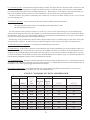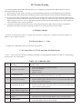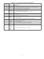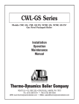
1
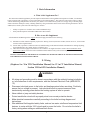
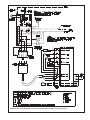
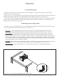
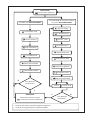
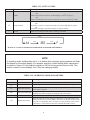
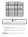
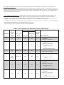
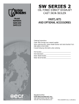
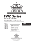
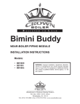
D E S I G N E D T O L E A D TWZ/CT/ODV Series Oil-Fired Hot Water Boilers (Less Tankless Heater) Installation Supplement for boilers equippEd with honeywell L7248L “2012 Compliant” boiler control These instructions must be affixed on or adjacent to the boiler Warning: Improper installation, adjustment, alteration, service or maintenance can cause property damage, injury, or loss of life. For assistance or additional information, consult a qualified installer, service agency or the oil supplier. Read these instructions carefully before installing. Manufacturer of Hydronic Heating Products P.O. Box 14818 3633 I. Street Philadelphia, PA 19134 www.crownboiler.com I Basic Information A. What is this Supplement For? This instruction manual supplement provides important information on the installation and operation of TWZ, CT and ODV boilers equipped with a proprietary version of the Honeywell L7248L Aquastat®. This control is being used in order to comply with the 2007 Energy Independence and Security Act (EISA). The L7248L-based system saves energy using a “thermal purge” feature which first attempts to satisfy a heating demand by using residual heat in the boiler before allowing the burner to fire. In addition, this control system offers the following new features: • • Ability to operate two circulator zones without additional relays. Easily installed optional 120V FWZ/TWZ LWCO Kit #411000 B. How to use this Supplement All information and Warnings in the original manual still apply EXCEPT for the following: a) Information in this manual completely replaces the “Wiring” Section (Section X in TWZ, Section IV in CT , Section VIII in ODV) in the original manual b) Section XII (“Operation”) and Section XIV (Troubleshooting) in this manual includes information for reading, adjusting, and troubleshooting the L7248L which is completely new. c) TWZ Series boilers equipped with tankless coils continue to be supplied with an L7224A. These instructions do not apply to this control; refer to the boiler installation manual and the Honeywell instructions provided with the L7224A. INSTALL AND SERVICE THE BOILER IN ACCORDANCE WITH THE ORIGINAL INSTRUCTIONS EXCEPT FOR THOSE SECTIONS LISTED ABOVE. X. Wiring (Replaces Sec. X in TWZ Installation Manual, Sec. IV in CT Installation Manual, Section VIII in ODV Installation Manual) WARNING • All wiring and grounding must be done in accordance with the authority having jurisdiction or, in the absence of such requirements, with the National Electrical Code (ANSI/NFPA 70). • Disconnect electrical power to the boiler and heating system before servicing. Positively assure that no voltage is present. Lock electrical boxes to prevent someone from inadvertently restoring power before the heating system is safe to operate. • Never defeat or jump out safety devices. • Protect each boiler circuit with a properly sized over-current protection device. • Make electrical connections carefully according to the boiler’s wiring diagram and instructions. • Wire additional field supplied safety limits, such as low water cutoffs and temperature limit devices, in series with the 120V circuit used to power the boiler. Do not alter the boiler’s factory wiring when adding an additional limit device. 1 1) 120 Volt Wiring - The boiler should be provided with its own 15A branch circuit with fused disconnect. 120VAC power connections are made inside the L7248L as follows (also see Figures. 10.0 or 10.2 as appropriate for boiler model): • • • Hot (“black”) - Terminal “L1” Neutral (“white”) - Terminal “L2” Ground (“green” or bare) - Ground screw on case of L7248L. The circulator is either factory wired to the L7248L or the boiler is provided with a flexible conduit “whip” that is factory wired to the L7248L circulator connections. If the circulator is not already wired to the control, connect it as follows: • Circulator “Hot” - Black wire lead from “whip” • Circulator “Neutral” - White wire lead from “whip” • 2) Low Voltage Connections – Low voltage field connections are located as shown in Figure 10.0/10.2 and are as follows: • T-T - Connect to a 24 volt heating thermostat or other “dry contacts” (such as a zone panel end switch) that close upon a call for heat. Follow thermostat manufacturer’s instructions. To insure proper thermostat operation, avoid installation in areas of poor air circulation, hot spots (near any heat source or in direct sunlight), cold spots (outside walls, walls adjacent to unheated areas, locations subject to drafts). Provide Class II circuit between thermostat (or zone controls) and boiler. • 1,2,3 - Used to connect EnviraCom thermostat, or other EnviraCOM device, approved by Crown for use with this boiler (refer to instructions provided with EnviraCOM device). 3) Adding a Second Circulator Zone - The L7248L provided with this boiler can be used to control a second heating or DHW circulator zone. If this is done, make the following 120VAC connections in addition to those described above (also see Figure 10.0 or 10.2): • • Connect a 120VAC heating or DHW thermostat for the second zone between L1 and ZR. Connect the circulator for the second zone between ZC and L2. See Part XII of this manual for information on configuring the control to respond properly to this second zone. 4) Low Water Cut-offs - A properly installed low water cut-off (LWCO) prevents burner operation in the event that there is insufficient water in the boiler. Many jurisdictions require the installation of a LWCO, as does NFPA-31. Install the LWCO in the supply piping immediately above the boiler with no intervening valves. If a probe type LWCO is used, observe the LWCO manufacturer’s required clearances around the probe. Use a LWCO that is wired so as to interrupt 120volt power to the boiler in the event of a low water condition. Crown 120V FWZ/TWZ LWCO Kit #411000 includes the LWCO, fittings, and wiring needed to meet the above requirements. CAUTION • When making low voltage connections, make sure that no external power source is present in the thermostat circuits. If such a power source is present, it could destroy the boiler’s control. One example of an external power source that could be inadvertently connected to the low voltage connections is a transformer in old thermostat wiring. • Do not attempt to use EnviraCOM connections for any purpose not explicitly permitted by Crown Boiler Company. Attempting to do so may result in unreliable operation and/ or damage to controls. • Do not use the transformer provided on the boiler to power external devices such as zone valves. Doing so may cause damage to the transformer. 2 FIGURE 10.0: TWZ, CT BOILERS: CONNECTIONS DIAGRAM FOR L7248L AQUASTAT® 3 Riello 530SE: Beckett 7505: Carlin 40200: FIGURE 10.1: TWZ, CT BOILERS: CONNECTIONS DIAGRAM FOR BURNER PRIMARY CONTROLS 4 FIGURE 10.2: ODV BOILERS: CONNECTIONS DIAGRAM FOR L7248L AQUASTAT® 5 XII Operation A. General Information This boiler uses a proprietary version of the Honeywell L7248L Aquastat® to regulate water temperature and to manage demands from up to two circulator zones. Crown offers a low water cut-off kit that may be used with this control (PN 411000). Specific information on this kit, along with installation and operating instructions, are available through Crown distributors and at www.crownboiler.com. In accordance with the 2007 Energy and Independence Security Act, this control first attempts to use residual heat in the boiler to satisfy a space heating demand before firing the burner. In this manual, this function is referred to as a “thermal purge”. For additional information see Part C of this section. B. Reading Status and Using Menu The boiler’s status, as well as all parameters, are viewed and adjusted using the 3 digit LED and three buttons shown in Figure 12.0. The L7248L has four basic modes of operation (also see Figure 12.1): 1. Status Mode - This is the default mode of operation for the control. In it, the display alternates between StA and a number indicating the current status of the boiler. A list and description of these status numbers is shown in Table 12.2. 2. Operating Mode - Provides additional information about the current status of the boiler. Operating mode is entered by pressing the I button shown in Figure 12.0. When this button is first pressed in Status mode, the display will alternately display bt and the current boiler water temperature as shown in Figure 12.3. Pressing the I button again will display the next line item shown in Table 12.2. In the same manner it is possible to advance through all of the “parameters” shown in Table 12.2. To return to Status mode, press I repeatedly until StA once again appears on the display. Alternatively, the control will return to Status mode if no key is touched for 1 minute. 3. Error Mode - In Error mode, the control alternately displays Err and an error code. A list of these error codes is found on the inside of the control cover, as well as in Section XIV of this manual (along with suggested corrective actions). 4. Adjustment Mode - Used to change parameters, such as high limit setting. See Part C for using Adjustment Mode. FIGURE 12.0 LOCATION/APPEARANCE OF LED, BUTTONS 6 FIGURE 12.1: BOILER CONTROL MENU STATUS MODE: 6W$=Current Status (Table 12.2) Press and Hold I, ↑, and ↓ for at least 3 sec to enter ADJUSTMENT MODE Press I to enter OPERATING MODE +/= High Limit Setting EW= Current Boiler Temp. +G) = Limit Differential &=Use of 2nd Zone 63= Current Set Point 2U=Circulator Overrun +/= High Limit Setting 33=Thermal Purge Time +G) = Limit Differential 6W=Thermal Purge Temp KU=Call for Heat? (On/Off) 3W=DHW Priority (ON/OFF) GK=Call for DHW? (On/Off) )&=Temperature Units N E$F=Return to Status Mode Error Detected by Aquastat®? Press I Press ↑ or ↓ Y Y ERROR MODE (Visible when Lockout is Present) (UU = Code for Error Present (Table 14.0) Error Detected by Aquastat®? N Except as shown above, press I to navigate through menu. Use ↑,↓ to change parameters in Adjustment Mode 7 Status # TABLE 12.2: STATUS CODES Meaning Description 1 Standby 8 Burner Demand No call for heat or DHW OR Call for heat present , but boiler is in thermal purge (See PP on page 11) OR Call for heat/DHW present but boiler temperature is above set point (SP) setting. The burner is running OR The burner is off due to an open limit (such as an external high limit or LWCO) OR The burner is being prevented from firing by its primary control. Self test 17 Boiler was just energized and control is running a self check. 1 sec. 1 sec. 1 sec. FIGURE 12.3: TYPICAL OPERATING MODE DISPLAY (BOILER TEMP SHOWN) NOTE In operating mode, holding either the ↑ or ↓ button while viewing a given parameter will keep the display on the actual reading. For example, pressing ↑ while reading boiler temperature as shown in Figure 12.3 will keep the display on 180 for as long as this button is held. This makes it easier to view readings “live” if they are changing rapidly TABLE 12.4: OPERATING MODE PARAMETERS Parameter # bt SP HL HdF hr dh Description Meaning Boiler Temperature Current boiler water temperature measured by the control’s sensor. Boiler water set point Current target temperature (always the same as the high limit setting) Boiler will stop firing if boiler water temperature exceeds this value (Circulator/s will continue to operate) If high limit setting is reached, boiler water temperature will need to drop by this High Limit Differential amount before boiler will again fire during the same call for heat. High Limit Set point Heat Request Status Shown as either ON or OFF. Indicates whether there is a call for heat. DHW Request Status Shown as either ON or OFF. Indicates whether there is a demand from the ZR terminal for domestic hot water (DHW). Note that if the dh zone on the L7248L is used as a second heating zone (see Table 12.5), this parameter will be shown as OFF and hr will be shown as ON when a demand from ZR is present. 8 TABLE 12.5: ADJUSTMENT MODE PARAMETERS Factory Status # Description Setting Permissible Range High Limit Set point 180F 140-220F HL High Limit Differential 15F 10-30F HdF ZC ZC and ZR Terminal Function dh dh (DHW) OR Zr (2nd Heating Zone) OR ELL (“External Low Limit” NOT RECOMMENDED) Or PP Circulator overrun 0 min 0-10 minutes Thermal Purge time 2 min 2-20 minutes St Thermal Purge Start Temp 140F 140-180F Pt DHW Priority ON ON or OFF F-C Temperature Units F F or C bAc Exit Adj. mode N/A N/A C. Using Adjustment Mode WARNING Improper adjustments to control parameters could result in unreliable boiler operation, property damage, personal injury, or loss of life. Adjustments should only be made by a qualified heating technician. A list of parameters which can be changed on this control are shown in Table 12.5. To enter Adjustment mode and change parameters: 1) Press and hold I, ↑, ↓ together for at least 3 seconds. 2) Use I to advance to the parameter which is to be changed. 3) Use the ↑ or ↓ buttons to change the setting or select from possible choices. See below for additional information on the use of these parameters. 4) If other parameters are to be changed, use the I button to advance to the next parameter needing adjustment and change it in the same way. 5) After all parameters have been changed, use the I button to advance until bAc is shown on the display. 6) Press either the ↑ or ↓ key to return to Status mode. Alternatively, the control will return to Status mode if no key is touched for 5 minutes. HL (High limit Set point) - Burner shuts down if the boiler water temperature exceeds this setting. The circulator will continue to run. The high limit setting also serves as the water temperature set point (SP) during calls for both heat and DHW. 9 HdF (High limit differential) - If the boiler shuts off on high limit, the water temperature must fall by an amount equal to the differential during the same call for heat before the burner will again start. For example, with HL=180 and HdF=15, the burner will shut off if the water temperature exceeds 180F and stay off until the temperature falls to 165F (180 - 15). Note that if all calls for heat end while the burner is off on high limit, the burner will not restart during the next call for heat until the thermal purge requirements described below are met. ZC (ZC and ZR Terminal Functions) - Terminals ZC and ZR can be used to control a second DHW or heating circulator zone using a 120VAC thermostat (see Section X). When ZC=dh, the L7248L assumes that an indirect water heater circulator is connected to ZC and no thermal purge occurs upon a call for DHW before the boiler fires (see thermal purge description below). In addition, a call for DHW will turn off the circulator connected to C1 and C2 if DHW priority (Pt) is ON. Setting ZC = Zr allows the second zone to be used as a heating zone. In this mode, there is no zone priority and a thermal purge occurs regardless of whether the call for heat originates from T-T or ZR. The use of the ZC=ELL (“External Low Limit”) is not recommended. TABLE 12.6 EXAMPLES OF THERMAL PURGE OPERATION Thermal Purge Settings Boiler Example # Call for Heat From 1 T-T N/A 2 min. 140F 130 2 T-T N/A 2 min. 140F 150 3 ZR DHW (ZC=dh) 2 min. 140F 150 4 Heat T’stat on ZR terminals Use of “ZC” Start Temp Zone Time (Pt) (St) Heat (ZC=Zr) 2 min. 140F Temp at Begin Call Boiler Behavior • • • • 2 minutes have passed OR Temperature falls below 140 • • “ZC” Circulator starts immediately Burner fires immediately • • “ZC” Circulator starts immediately Burner fires when either: 150 • 5 T-T N/A 2 min. 145F 150 • • 6 T-T N/A 3 min. 140 10 150 “C1-C2” Circulator starts immediately Burner fires immediately “C1-C2” Circulator starts immediately Burner fires when either: • 2 minutes have passed OR Temperature falls below 140 “C1-C2” Circulator starts immediately Burner fires when either: 2 minutes have passed OR Temperature falls below 145 “C1-C2” Circulator starts immediately Burner fires when either: 3 minutes have passed OR Temperature falls below 140 Or (Circulator Overrun) - Determines how long the Heating Circulator will operate after the call for heat ends. In some cases, this can help reduce energy consumption by sending heat stored in the boiler out into the system. At the same time, caution should be exercised before setting this value to something other than zero. Before doing so, verify that the system will permit flow (e.g. flow is not completely cut-off by closed zone valves) and that the overrun will not cause overheating problems. Circulator overrun is only possible on the heating zone controlled by T-T. The ZC Circulator will not over-run, even if it is used as a second heating zone. PP (Thermal Purge Time) - Upon a call for heat, the boiler will prevent burner operation until either: • • The water temperature drops below the Thermal Purge Start Temperature (St) OR: The thermal purge time has passed For some examples of this operation, see Table 12.6. If the “ZC” zone is used for space heating (ZC=Zr), this thermal purge function will also keep the burner off at the beginning of a call from the thermostat connected to the “ZR” terminal in the manner described above. If the “ZC” zone is being used for DHW (ZC=dh), the burners will immediately come on upon a call for DHW as long as the water temperature is below the high limit setting. Thermal purge is only invoked when a call for heat first appears and the boiler is not already firing. For this reason, if the boiler is already firing in response to an call for heat, and a call for heat appears at the second zone, the boiler will continue to fire. St (Thermal Purge Start Temperature) - See description for Thermal Purge Time above. Pt (DHW Priority) - If this feature is turned on, and simultaneous calls for heat and DHW are present, the heating circulator will be forced off for as long as it takes the boiler to satisfy the call for DHW. This feature is sometimes useful when the boiler size is marginal for the peak DHW demand, but should be used with caution as it can result in lack of heat if the DHW call is very long, or if there is a problem with the DHW zone which causes the DHW demand to be indefinite. Figure 12.7 describes the behavior of both the Heating and DHW Circulators with Pt turned both ON and OFF. F-C (Temperature Units ) - Determines whether temperature units on the L7248L are displayed in F or C. Note that this selection only applies to the temperature displayed on the LED shown in Figure 12.0. Temperature units must be selected independently on the displays of any control options plugged into the EnviraCOM port. bAc (Return to Status mode) - Exits adjustment mode. Any changes made to the parameters described above are saved, and become effective, as soon as they are made; bAc only exits adjustment mode. TABLE 12.7 SUMMARY OF CIRCULATOR BEHAVIOR Thermostat Inputs Parameters Circulator Outputs Use of DHW “ZC” 2nd Zone Priority T-T “DHW” Zone (Zc) (Pt) “C1-C2” “ZC- L2” ON OFF DHW Zc=dh ON ON OFF OFF ON DHW Zc=dh ON OFF ON ON ON DHW Zc=dh ON OFF ON ON ON DHW Zc=dh OFF ON ON ON OFF DHW Zc=dh OFF ON OFF OFF ON DHW Zc=dh OFF OFF ON ON OFF Heat Zc=Zr ON or OFF ON OFF OFF ON Heat Zc=Zr ON or OFF OFF ON ON ON Heat Zc=Zr ON or OFF ON ON 11 XIV Trouble Shooting The following tables contain trouble shooting tables for use in diagnosing control problems. When using these tables the following should be kept in mind: 1) This information is only meant to be used by a professional heating technician as an aid in diagnosing boiler problems. 2) Where applicable, follow all precautions outlined in the Start-up and Checkout Section of the boiler installation manual. 3) In general, these tables assume that there are no loose or miswired electrical connections. Before using these tables inspect all electrical connections on the boiler to make sure that they are tight. Also, check the wiring on the boiler against the wiring diagram in Figures 10.0/10.1 or 10.2, as appropriate for the boiler model. Ensure that incoming 120 VAC power polarity is correct and that the boiler is properly grounded. 4) All controls on the boiler are tested at least once in the manufacturing process and a defective control or component is generally the least likely cause. Before replacing a component, try to rule out all other possible causes. A. If Display is Blank Check for 120 VAC across L1 and L2. If voltage not present turn on system power. If voltage is present check polarity. If polarity is correct replace the control. B. If Control Shows Err Code Use Table 14.0 to help identify and correct the cause of the problem. C. If Control Shows StA Code, but Other Problem Present If no Err Code is observed (even after repeatedly pressing I to cycle through Operation Mode), use Table 14.1 to help identify and correct the cause of the problem. TABLE 14.0 - ERROR CODES Error Code Meaning Possible Cause 1 Temperature Sensor Fault 2 Communication Fault 3 Internal electronics failure • • • • • • • • 4 Burner Output (B1) Fault • • 5 Line voltage error (Supply voltage too high or low) • Loose connection between sensor and control Sensor wire damaged Defective Sensor Defective control EnviraCOM wiring is shorted to ground or line voltage Field wiring to external Enviracom device is incorrect. AC power supply frequency problem Possible internal problem with boiler control. Cycle power to the boiler and replace control if problem persists. Application of power to B1 from external source (control miswired) Possible internal problem with boiler control. Cycle power to the boiler and replace control if problem persists. Power supply voltage is incorrect (should be 120VAC nominal) 6 Open fuse in L7248L • Incorrectly wired burner primary control (See Section X). 7 8 User settings lost (reset to factory • defaults) • L7248L Lockout Clear error by entering and exiting the Adjustment mode (and changing settings back to user values as needed). Replace control if problem persists. Set if Err 4 was invoked four times in a row. Check wiring and clear Lockout by pressing all three user keys for 30 seconds. 12 TABLE 14.1 - FAULTS WITHOUT ERROR CODE PRESENT Displayed Codes Problem Possible Cause Burner and Circulator Off • • • • Thermostat/s not calling for heat Loose connection in thermostat, zone valve end switch, or zone panel wiring. Thermostat, zone valve, or zone panel miswired Defective thermostat, zone valve, or zone panel StA 1 hr On Burner Off Circulator On Boiler Warm • • Boiler off on high limit (normal operation) Boiler off on thermal purge (normal operation - See Table 12.6) hr On Heating Circulator Off • • • • • Heating Circulator is being forced off on DHW priority (normal operation if Pt=ON see Table 12.7). See causes for “DHW Circulator off “ below Loose connection in circulator wiring Defective circulator Circulator is running, but system problem is preventing circulation • • • • External Limit or LWCO is open. Burner is unplugged Loose connection between B1-B2 on L7248L and burner Loose or missing T-T jumper on burner primary control. • Consult burner documentation for cause of problem. StA 1 hr OFF dh OFF dh On StA 8 StA 8 DHW Circulator Off Burner Off No LEDs illuminated on Burner Primary control Burner Off LED is illuminated on Burner Primary control 13 Manufacturer of Hydronic Heating Products P.O. Box 14818 3633 I. Street Philadelphia, PA 19134 www.crownboiler.com PN: 980200 08/12