1
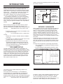
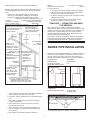
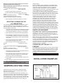
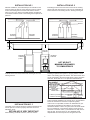
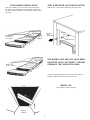
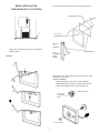
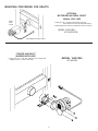
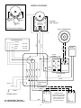
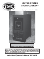
UNITED STATES
STOVE COMPANY
Keeping America Warm Since 1869
MODEL: 1600 / 1800
THE WOOD AND COAL FURNACE
SAFETY NOTICE: IF THIS FURNACE IS NOT PROPERLY INSTALLED, A HOUSE FIRE
MAY RESULT. FOR YOUR SAFETY, FOLLOW THE INSTALLATION DIRECTIONS.
CONTACT LOCAL BUILDING OR FIRE OFFICIALS ABOUT RESTRICTIONS AND
INSTALLATION REQUIREMENTS IN YOUR AREA.
Installation/Operator's Manual #851062E
TABLE OF CONTENTS
Introduction ..........................................................................1
Locating Your Furnace .........................................................1
Clearances ...........................................................................1
Chimney Requirements .....................................................1-2
Smoke Pipe Installation .....................................................2-3
Dampers on Stove Pipes ......................................................3
Installation Examples ........................................................3-4
Assembly Instructions .......................................................5-8
Electrical installation .............................................................9
Draft Wiring Diagram ..........................................................10
Testing and Operating Procedures.................................11-12
Trouble Shooting and Problem Solving .............................13
Parts Lists
Model 1600/1800 .....................................................14-16
Motorized Natural Draft ................................................17
Forced Air Draft............................................................18
Optional Electronic Control System
Installation ....................................................................19
Parts List Model 1600 ..................................................19
Wiring Diagrams.......................................................20-23
Installation of Optional Equipment
Domestic Hot Water Coil ..............................................24
Back Draft Damper ......................................................25
Filter Boxes..............................................................26-27
TC
chimney connector and extending at least 2" on either side of
the chimney connector.
INTRODUCTION
CLEARANCES
Thank you for your purchase of a U.S. Stove Woodburning
furnace. Your decision to buy a Hotblast Furnace was
undoubtedly reached after much careful thought and consideration. We are very proud you chose the U.S. Stove furnace
and trust you
will receive the comfort and economy that
others realize when heating with a U.S. Stove product.
Your dealer is important in your experience with the Furnace
not only in your purchase, but in his recommendations
for professional installation in your home. The qualified
professional installer (as recommended by your dealer) has
been expertly trained in solid-fuel furnace installation to
assure the safety and comfort for your family while saving you
money. Trust your experienced installer. He is a specialist in
his field.
FLAMMABLE WALL
MODEL 1600 - 20"
MODEL 1800 - 25"
(TOP VIEW)
MODEL
1600 - 22"
1800 - 19"
MODEL
1600 - 12"
1800 - 8"
MODEL 1600 - 15"
MODEL 1800 - 18"
‰
FLUE
‰
MINIMUM
CLEARANCE TO
FLAMMABLE WALLS
CAUTION: Do not
store combustible or
flammable material
near furnace.
IMPORTANT
Before installing and using your Hotblast Furnace, please
read the following pages thoroughly and carefully. If you
follow the instructions, your Hotblast furnace will give you safe
and more
dependable service in the years to come.
REDUCED CLEARANCES
NFPA guidelines and most codes permit reduced clearances
to combustible walls and ceilings if adequate protection is
added. A common mistake is to assume that sheet metal,
masonry, or asbestos board placed directly against a wall
protects it. Materials installed in this manner give very little
protection. These materials are good heat conductors, so they
will be almost as hot on their back side as they are on the
exposed side. Therefore, the combustible wall behind is still a
fire hazard.
A wall can be kept cool using these items but only if they're
mounted and spaced out from the wall by an inch or two to
allow free circulation of room air behind the protective panel.
The protective panel should start within a few inches of floor
level.
The three rules to follow when constructing wall protectors:
1. Non-combustibility of all materials including mounting
or supporting.
2. A well ventilated air space between protector or wall.
3. Sufficient strength and rigidity so that the protector and
2" FROM
CEILING
air space
will be durable.
✑First step; check your local codes. This installation must
comply with their rulings.
✒
or trailer.
Do not install this furnace in a mobile home
✓ Always have a smoke or ionization detector installed in
your home.
4 To prevent injury or damage, do not allow anyone who is
unfamiliar with the furnace to operate it.
✕ Spend some time with your furnace to become well
acquainted with different settings and how each will
affect its burning patterns. It is impossible to state just
how each setting will affect your furnace because of
the variations in each installation.
DISCLAIMER NOTICE
The BTU ranges and heating capacity specifications are
provided as a guide only and in no way guarantee the output
or capacity of the units. The actual BTU output depends on the
type of fuel being burned and its conditions, the thermostat
setting, the draft adjustment and the chimney that the unit is
hooked up to. The actual area that the unit will heat depends
on factors such as the conditions of the building, heat loss,
type of construction, amount of insulation, type of air movement, and the location of the unit.
CONSTRUCTING
NON-FLAMMABLE
WALLS
PROTECTIVE COVERING
AND ALL SUPPORTS MUST
BE NON-COMBUSTIBLE.
1" AIR SPACE
2" FROM FLOOR
LOCATING YOUR FURNACE
CHIMNEY REQUIREMENTS
The furnace is to be installed maintaining clearances as
shown in illustration.
Do not place the furnace directly on a combustible floor.
If you're placing it on a combustible floor, an approved fire
retardant material equivalent to 3/8" asbestos millboard
should be placed under the furnace. The material must extend
at least 16" in front of and 8" on either side of the fuel-loading
and
ash-removal doors, and underneath the
A masonry or Class A All-Fuel Metal Insulated Chimney must
be used in all airtight wood furnace installations. The minimum recommended flue size for the U.S. Stove Hotblast
Furnace is 6" (inside diameter) for round flues, and 7" x 7" for
square flues. When making new chimney installations,
1
always follow the chimney manufacturers instructions.
highest
point of the house, or 2'
above the point at which the
chimney
is 10' from the roof.
7. The chimney should be relatively straight and vertical.
8. The portion of an all-fuel metal chimney that extends
above the roof should be well secured.
9. A masonry chimney should be built on footings and not
attached to the house.
10. A rain cap, complete with an animal or bird screen,
should be installed on top of the chimney.
NOTE: Type of chimney: Class A All-Fuel also referred to as
Low-Heat appliance type chimney per Uniform Mechanical
Code:
Chimney, low-heat appliance type is a factory built,
masonry or metal chimney suitable for removing the
products of combustion from fuel-burning low-heat
appliances producing combustion gases not
in excess
of 1000°F under normal operating
conditions but capable
of producing combustion
gases of 1400°F during
intermittent
forced firing for periods up to one hour.
All
temperatures are measured at the appliance flue outlet.
TOP OF CHIMNEY MUST BE
2 FT. ABOVE HIGHEST
POINT OF ROOF
2 FT.
MINIMUMS
APPROVED
CHIMNEY
When wood is burned slowly, it produces tar and other
organic vapors, which combine with expelled moisture to form
creosote. The creosote vapors condense in the relatively cool
chimney flue of a slow-burning fire. As a result, creosote
residue accumulates on the flue lining. When ignited, this
creosote makes an extremely hot fire.
The chimney connector and chimney should be inspected at
least twice monthly during the heating season to determine if
a creosote build-up has occurred. If creosote has accumulated,
it should be removed to reduce the risk of a
chimney fire.
CAP SHOULD HELP
PREVENT DOWNDRAFT
WHILE STILL PROVIDING
ADEQUATE EXHAUST.
3 FT.
MINIMUM
RECOMMENDED
MINIMAL
20 FT. HEIGHT
MINIMAL 3 FT.
FROM TOP OF
CHIMNEY TO POINT
AT WHICH IT PASSES
THROUGH THE ROOF.
CHIMNEY FLUE
SHOULD BE
CONSTANT DIAMETER
THROUGHOUT ITS
ENTIRE HEIGHT.
CREOSOTE — FORMATION AND NEED
FOR REMOVAL
SMOKE PIPE INSTALLATION
Clearances to combustible materials (i.e. paneling, ceiling tile,
sheet rock, plaster, draperies, casements or wood trim, etc.)
will vary with the type of flue connection used. Be sure to
maintain the specified clearances for your type of installation.
TYPE OF FLUE
REQUIRED
CONNECTION
CLEARANCE
24 Gauge or Heavier
18"
Single Wall Stainless Steel
CHIMNEY FLUE
MUST BE AS
LARGE OR
LARGER THAN
FURNACE FLUE
PIPE
COMBUSTIBLES
CLEANOUT DOOR
SHOULD HAVE
AIRTIGHT FIT. DO
NOT LEAVE OPEN
WHEN FURNACE IS
IN OPERATION.
SMOKE PIPE
CHIMNEY THIMBLE SHOULD BE
CONSTRUCTED OF FIRE CLAY, AND
SHOULD FIT TIGHTLY TO FLUE PIPE.
or Black Pipe
Double Wall Stainless Steel
1. The wood furnace should be the only heating appliance
using a chimney flue. One furnace per flue.
2. A masonry chimney should have a tile or stainless steel
liner.
3. The masonry chimney should not have any missing
mortar or loose bricks.
4. There should be no mortar or parts of the chimney
blocking the chimney flue.
5. There should be a two inch clearance between any
chimney (masonry or metal) and combustibles (such
as the house).
6. The chimney should extend at least 2' above the
6" Model 1600
8" Model 1800
Class A All-Fuel or Equivalent 2"
According to NFPA standards, single wall stove pipes can be
within 9" of combustibles provided an approved fire retardant
material covered with 28 gauge sheet metal, spaced out 1" on
18"
9"
18"
CEILING OR WALL
non-combustible spacers, is utilized. See illustration.
2
When using a Class A or double wall flue pipe connection,
follow the manufacturer's instructions.
When constructing a single wall smoke pipe, the following
guidelines must be observed.
1. The smoke pipe should be 24 gauge or heavier
stainless
steel or black pipe.
heating season.
DO NOT CONNECT TWO HEATERS TO THE SAME CHIMNEY FLUE. The National Fire Prevention Association recommends that woodburning appliances vent into a separate
chimney from gas or oil furnaces. If such an installation is
contemplated, first check with a local building inspector to find
out if a separate flue for a woodburner is required.
If codes allow, use extreme care in making such installations.
Be sure that one pipe is higher than the other so that the two
openings will not be opposite each other. Also, when connecting two heaters into the same chimney flue, the flue size
should be large enough to handle both heaters. Very few
codes and standards allow same flue connection. Such
installations can cause severe problems. Gas hoods and
barometric dampers allow excess air into the chimney
causing cooling of the flue gases and a greater creosote
build-up potential. If the same flue connections are used,
chimneys must be inspected more frequently and the chimney
should be cleaned any time the creosote deposits exceed 1/4"
thickness. A creosote fire in such a chimney can burn out of
control because of the air leak through the barometric damper
or gas hood. Keeping the chimney clean and burning wellseasoned wood is absolutely necessary. This type of installation does require more frequent inspection and maintenance.
2. Secure all joints with three #8 screws.
3. If the smoke pipe must pass through a wall, an approved
insulated or ventilated
thimble, at least three times the
diameter
of the smoke pipe must be used. (i.e. a 6"
diameter smoke pipe needs an 18" thimble).
4. The smoke pipe should not be used as a chimney.
IMPORTANT INFORMATION FOR
ALL SMOKE PIPES
The smoke pipe must be constructed and installed so that it
maintains clearances, keeps condensation and creosote
within the pipe, and is capable of withstanding a two to three
thousand degree chimney fire.
1. The smoke pipe should slant down toward the furnace a
minimum of 1/4" to the foot. At no time should the pipe
turn downward toward the chimney or run horizontal.
HEATED AIR DISCHARGE
The Hotblast furnace is designed for use as a supplemental
heating source. When used as a supplementary furnace, the
1600/1800 is connected in conjunction with an oil, gas, or
electric furnace to the existing duct work which distributes the
heated air into several rooms and/or areas.
When used as a space heater, heated air from the 1600/1800
furnace is expelled directly into the room in which the furnace
is located. In installations of this type, the flow of heated air
from the furnace must not be blocked. It is recommended that
an elbow be attached to the heated air discharge to divert the
heated air away from combustibles. All other criteria for
installation remains unchanged.
2. There should be no more than two 90 degree elbows.
3. The smoke pipe should never be longer than six feet.
If it is absolutely necessary to make a run of more than
six feet (not recommended) use extra support brackets
every 3 feet.
4. The smoke pipe should never be reduced to a smaller
size than flue opening on the furnace.
5. The smoke pipe should not block the flue of the
chimney
or extend into it in any
way.
CONNECTING HOT AIR DUCT TO
FURNACE
6. A good airtight thimble should be used to hold the
smoke
pipe in the chimney. It
should be constructed so the
smoke
pipe can be removed for cleaning.
We strongly recommend that the hot air duct work be installed
by a home heating specialist. If doing the installation yourself,
before you decide which installation will best suit your needs,
consult a qualified heating technician and follow his recommendations as to the safest and most efficient method of
installation.
The following illustrations are the only acceptable configurations when installed with existing oil or gas furnaces.
7. The smoke pipe should not leave the heated portion of
the building to reach the chimney.
8. The smoke pipe should not pass from one story to the
next before entering the chimney, nor should it pass
through any closed or enclosed space.
9. Heat reclaimers should not be installed or used in the
smoke pipe.
INSTALLATION EXAMPLES
10. The smoke pipe should not be located near or in a walk
way or well traveled area.
11. All male ends of smoke pipe should run or point
towards
the furnace.
DAMPERS ON STOVE PIPES
BACK
DRAFT
DAMPER
When burning coal, we recommend a Barometric Draft
Damper be installed at a safe convenient place between
chimney and your furnace.
When you have installed the smoke pipe connecting your
furnace to the chimney, tap the pipe hard with your fingernail.
Remember the sound it makes - it will be a "ting" echoing
inside the stove pipe. If later you tap and hear a muffled thud,
you are building up soot in the pipe and should clean it. This
pipe should be cleaned at least once or twice during the
HOTBLAST
FURNACE
3
EXISTING
FURNACE
INSTALLATION NO.1
INSTALLATION NO. 2
With this installation, a back draft damper is inserted into the
heat run before the plenum of the existing furnace to prevent
air from the existing furnace to blow back into the furnace
when it is not in use. When a back draft damper is employed,
it should be located as close to the existing furnace plenum as
practical.
Extending the hot air duct from the furnace into the existing
plenum will help direct the flow of air from the 1600/1800 as
well as the flow in the existing furnace. Ducting entering the
BAFFLE
EXISTING
FURNACE
HOTBLAST
FURNACE
HOTBLAST
FURNACE
EXISTING
FURNACE
2" MIN.
1" MIN.
9 FEET
9 FEET
HOT AIR
PLENUM
EXISTING
FURNACE
(if used)
1" MIN.
HOTBLAST
FURNACE
HOT AIR DUCT
MINIMUM CLEARANCES
TO COMBUSTIBLES
existing plenum at an angle (approximately 45 degrees) will
facilitate air flow from the furnace while diverting air from the
existing furnace.
incorporated into the system. Return air can be provided by
installing a separate duct system or by tying into the cold air
return of an existing gas or oil furnace. The cold air return duct
can be connected to the furnace with either a factory manufactured U.S. Stove filter box or an equivalent fabricated from
sheet metal (See pages 21-23).
INCORRECT
When installing a cold air return, the following minimum
INSTALLATION
size should be maintained to insure proper furnace
performance.
NO RETURN
Model 1600 — 16" x 20" or equivalent
AIR PROVIDED
Model 1800 --- 16" x 20" or equivalent
HOTBLAST
Failure to provide return air ducts
of the specifiedEXISTING
size
FURNACE
FURNACE
voids the furnace warranty.
A filter should be installed in the cold air return. Furnace filters
should be checked and cleaned or replaced regularly.
If return air is not provided, the warm air distributed into your
home will be restricted and the efficiency of the furnace
decreased. Without a return air system, warm air will be drawn
into your basement, unnecessarily heating unused areas of
the home. In extreme cases, if your basement or utility room is
fairly air tight, the large blower on the 1600/1800 could
depressurize the room and pull toxic flue gases from the
INSTALLATION NO. 3
The baffle on this system should be made the full width of the
furnace plenum in order to properly direct the air into the
distribution ducts.
RETURN AIR IS VERY IMPORTANT
When installing a Hotblast Furnace, return air must be
4
furnace, a gas water heater, or gas furnace. The fumes could
then be distributed throughout the house.
ASSEMBLY INSTRUCTIONS
Three 1/2" Lock Nuts
One 1/2" x 2 1/2" Carriage Bolt
Six 1/4" x 3/4" Hex Bolts
Smoke Door
Two 1/4" x 1-1/4" Carriage Bolts
to make sure there is no
shipping
damage, and that
COMBUSTION
AIR
all necessary
parts are
All fires need air (specifically oxygen)
to burn. Furnaces,
locatedneed
in the
firebox.
See
fireplaces, and wood-burning furnaces
enough
oxygen
parts The
list below.
for complete combustion of their fuels.
incomplete
combustion that takes place whenIfayou
furnace
is "air starved"
find shipping
damage
causes carbon monoxide (CO) to or
beany
formed
in parts
quantities
that
of the
missing,
can be dangerous inside a well-sealed
Having
a
contacthouse.
the dealer
immedisource of combustion air from outside prevents this "air
starvation" of the furnace.
MODEL 1600 - (6) BRICKS ON EACH SIDE
FIREBOX LEFT SIDE
Your furnace is shipped from the factory in four (4) packages.
1) the furnace, 2) the blower, 3) draft kit, 4) fan limit kit or
electronic circuit board . Before assembling the furnace, check
ately. He will take the necessary steps to correct the problem.
BRICK RETAINING STRIP
SLIDE 4th BRICK BACK
BEFORE INSTALLING 5th
AND 6th BRICK
Parts List
All models include the following:
Two Door Handles
One Fuel Door Latch
One Ash Door Latch
One Shaker Grate Handle
Two 1/2" Washers
Four 1/4" Hex Nuts
Four Lock Washers
Spin Draft
Five 1/4" Lock Nuts
One Pivot Bracket
Four Brass Coil Knobs
One 1/4" x 1" Hex Bolt
MODEL 1800 - (8) BRICKS ON EACH SIDE
FIREBOX LEFT SIDE
FUEL DOOR
ILLUSTRATION
BRICK RETAINING STRIP
ASH DOOR
ILLUSTRATION
Two Smoke Door Clips
Rod Extension
Manual
LOCK
WASHER
HEX
NUTS
5
DOOR HANDLE INSTALLATION
FUEL & ASH DOOR LATCH INSTALLATION
Insert door handle into door. From rear side of door place
1/2" washer over threaded part of door handle. Then attach
1/2" lock nut, being careful not to over tighten. Handle should
turn freely.
With two 1/4" x 3/4" hex bolts, attach the door latch to the
BAFFLE
ROD
EXTENSION
2
MODEL 1600
(41/2) BRICKS
1
BAFFLE
ROD
1-1/2"
HEX COUPLING
1/2 BRICK
3
5
4
6
THE MODELS 1600 AND 1800 HAVE BEEN
EQUIPPED WITH DIFFERENT PLENUM
OPENINGS, THEY ARE AS FOLLOWS:
2
MODEL 1800
(6) FULL BRICKS
1
4
3
5
6
door latch mounting bracket on the left side of door frame as
illustrated. Adjust latch until door closes securely.
7
TOP
MODEL 1800
18"x18" Square Plenum Opening
REAR OF
FIREBOX
6
The firebrick must be inserted on each side resting on the
BRICK INSTALLATION
(PRE-INSTALLED AT FACTORY)
SMOKE DOOR CLIPS
1/4" LOCK
NUTS
1/4" X 1-1/4"
CARRIAGE BOLTS
FRONT
OF
FURNACE
NOTE: Prior to operation, be sure to remove brick
retaining strips.
SMOKE DOOR
FUEL
LOADING
DOOR
FRAME
FIREBOX:
1
grate frame. First, place cut brick in each back corner. Place
remaining brick in place.
SMOKE CHAMBER:
1. Place #1 firebrick in the back of smoke chamber.
2. Slide baffle plate into smoke chamber, flat side down.
3. Place remaining firebrick in smoke chamber as
2
SPIN DRAFT CAP
1/2" X 2-1/2"
CARRIAGE
BOLT
3
1/2" LOCK NUT
7
MOUNTING PROCEDURE FOR DRAFTS
OPTIONAL
MOTORIZED NATURAL DRAFT
Models 1600 / 1800
DRAFT
TUBE
CLAMP
1. Using (2) 1/4" x 1" bolts, lock washers and nuts,
attach draft to furnace with draft tube clamp.
2. Plug draft power cord into receptacle on front of furnace.
MODEL 1600/1800 KIT #C60357M
MOTORIZED NATURAL DRAFT
FORCED AIR DRAFT
(SHIPPED WITH UNIT)
MODEL 1600/1800
1. Using (2) 1/4" x 1" bolt, lock washer and nut, attach draft
adapter bracket to furnace draft tube.
KIT #69189
8
ELECTRICAL INSTALLATION
Predrilled holes are provided on the back of the furnace
for mounting the fan center electrical box. Mounting
holes and knockouts are also provided to accommodate
mounting the high limit control in either the upper left or
upper right corner.
ALL WIRING MUST
BE DONE BY A
QUALIFIED
ELECTRICIAN
THERMOSTAT
The flexible conduit connecting the high limit control to
the fan center electrical box has been sized longer for
the model 1800. This conduit may be cut shorter to
provide a cleaner installation on model 1600.
HIGH
LIMIT
CONTROL
FAN
CENTER
CONDUIT
TO HOUSE
CURRENT
REAR VIEW
Wired to "G" on
fan center front
BLACK
DRAFT WIRING DIAGRAM
Wired to "G" on
fan center front
BLUE
ELECTRICAL BOX
BLACK
TO DRAFT
RED
BLUE
BLK
RedTo Draft
BlackTo High Limit
FLEXIBLE CONDUIT
TO HIGH LIMIT
CONTROL
BLK
RED
BLUE
BLK
TO
THERMOSTAT
GND
GR
BLK
2
SWITCH
LABEL
1
3
PUNCH
W
TO
"R"
W
L1
NUT
SET
SCREW
W
TO
"G"
WIRES TO
BLOWER
MOTOR
FAN
CENTER
W
3-SPEED SWITCH
MODEL "B" SHOWN
(SEE WIRING DIAGRAM
ON PAGE 10 FOR
WIRING OF MODEL "A"
SWITCH)
9
HOUSE
CURRENT
PLASTIC
KNOB
WIRING DIAGRAM
LIMIT
INDICATOR
(200)
FAN "ON"
INDICATOR
(150)
FAN "OFF"
INDICATOR
(100)
LOAD
FAN
LINE
Honeywell
LIMIT SWITCH
LOAD
LIMIT
BREAK OFF
JUMPER FOR LINE
LOW VOLTAGE
SETTING LIMIT CONTROL
WALL THERMOSTAT
BLACK
BLOWER MOTOR
1400 CFM
BLUE
1250 CFM
RED
1100 CFM
BLUE
BLACK
RED
WHITE
TO
"R"
DRAFT
MOTOR
TO
"G"
BLACK
WHITE
BACK VIEW
R
W
C
G
Y
RED
BLACK
FRONT VIEW
FAN CENTER
BLACK
WHITE
ELECTRICAL
BOX
BLACK
WHITE
BLACK
BLUE
GREEN
RED
3
POWER SUPPLY
ALL WIRING MUST BE DONE
BY A QUALIFIED ELECTRICIAN
RED
4
5
2
Model "A"
10
3-SPEED SWITCH
(Two Models are available
Model "A" and Model "B".
Check your switch to see
which model you have
and wire accordingly)
2
1
3
L1
Model "B"
TESTING AND OPERATING PROCEDURES
TESTING:
established, you are ready to load the furnace.
CAUTION: To prevent flame and smoke spillage, the slide
baffle must be pulled out and the fuel door must be cracked
for ten seconds before being fully opened.
Do not over fire your furnace! After you have become familiar
with its operating, you should know how much wood to use.
4. Load the furnace, close the load door and push the
slide Baffle rod to rear.
5. Close the spin draft cap on ash door.
6. The forced air draft cycles on demand from the
wall thermostat. Setting the U.S. Stove thermostat four
degrees higher than your existing thermostat is
recommended. In operation, the power draft blower will
run until the U.S. Stove thermostat temperature setting
is reached. The draft regulator on the forced air draft is
preset at the factory and should require no adjustment.
1. If using an optional power draft, check the draft blower
by turning the room thermostat up high enough so that
the draft blower turns on. Then lower the thermostat
setting until you hear it shut off.
2. Use a sheet of newspaper to test your draft by placing it
inside the furnace and lighting it.
With completion of the tests above, you are ready to light the
furnace. Follow the operating steps.
STARTING A WOOD FIRE
Using Motorized Natural Draft
CAUTION: Never use gasoline, gasoline-type lantern fuel,
kerosene, charcoal lighter fluid, or similar liquids to start or
"freshen up" a fire in the furnace. Keep all such liquids well
away from the furnace while it is in use.
1. Turn up thermostat to open motorized damper.
2. Open spin draft cap on ash door.
3. Pull the slide baffle rod to the front position.
4. Open the fuel load door and light fire using kindling and
several sheets of newspaper, then close the furnace
door. The furnace door should remain closed for 5 to
10 minutes in order to establish the fire. If the fire has
established, you are ready to load the furnace.
CAUTION: To prevent flame and smoke spillage, the slide
baffle must be pulled out and the fuel door must be cracked
for ten seconds before being fully opened.
Do not over fire your furnace! After you have become familiar
with its operation, you should know how much wood to use.
4. Load the furnace, close the load door and push the
slide baffle rod to rear.
5. Close the spin draft cap on ash door.
6. The motorized natural draft cycles on demand from the
U.S. Stove wall thermostat. Setting the thermostat
four degrees higher that your existing thermostat is
recommended.
During operation, the motorized natural draft remains
open until the thermostat temperature setting is
reached.
CAUTION: To avoid excessive temperatures, do not
operate with fuel door or ash pan open.
STARTING A COAL FIRE
If you burn coal a Forced Air Draft is required.
Shut off FAD when fuel door is open.
✓ Open smoke pipe damper all the way. Open all draft
controls on your 1600/1800. Pull the slide baffle forward.
✓ Place about 10-15 lbs. of coal in on the shaker grates.
It should come up to about half of the first firebrick level.
✓ Place crumpled paper over the coal and criss-cross a
couple handfuls of dry kindling wood 3/4" in thickness on
top of paper.
✓ Ignite the paper and close loading door. Wait about 30
minutes until coal fire is established before adding more
coal. NOTE: NEVER load coal over the level of firebrick.
✓ Close by-pass damper and set all draft controls to your own
needs. It may take 3 to 4 coal fires to determine how your
local coal and the Hotblast Furnace reacts together —
adjusts drafts accordingly.
✓ Loading with a good bed of coals in the morning — open
by-pass damper.
1. In normal shaking, only rock the grates a small amount
to sift ash through.
2. Remove all ashes every day from ash pit.
CAUTION: Ashes should be placed in a metal container
with a tight fitting lid. The closed container of ashes should
be placed on a non-combustible floor or on the ground
well away from all combustible materials pending final
disposal. If the ashes are disposed of by burial in soil or
otherwise locally dispersed, they should be retained in the
closed container until all coals have thoroughly cooled.
3. With your poker, push hot burning embers to the rear of
the unit and add green coal in front. NEVER load over
height of firebrick. This can result in damage to your
furnace and home.
4. Close by-pass damper.
✓ Too much draft air will cause clinkering of coal and will
waste heat up the chimney. Shut draft down to as low a
point as you can and still heat your home.
1. NOTE: Never stand in front of loading door when
opening it. Stand to the side.
CAUTION: To avoid excessive temperatures, do not
operate with fuel door or ash pan open.
STARTING A WOOD FIRE
Using Forced Air Draft
Shut off FAD when fuel door is open.
CAUTION: Never use gasoline, gasoline-type lantern fuel,
kerosene, charcoal lighter fluid, or similar liquids to start or
"freshen up" a fire in the furnace. Keep all such liquids well
away from the furnace while it is in use.
1. Open spin draft cap on ash door.
2. Pull the slide baffle rod to the front position.
3. Open the fuel load door and light fire using kindling and
several sheets of newspaper, then close the furnace
door. The furnace door should remain closed for 5 to 10
minutes in order to establish the fire. If the fire has
11
2. NEVER completely cover the live fire with fresh coal.
Always leave a generous area of burning coal at the top
of the fire and at the rear.
furnace any more than necessary early in the fall and late
spring, as you cannot keep the firebox hot enough (without
overheating your home) to burn gases. Slow fires can
cause excessive creosote build-up in smoke pipe, chimney
and firebox.
3. Always keep the ash pit clean.
✓ If the fire goes out or does not hold overnight, look for:
Wood should be placed directly onto the cast iron shaker grate
of the U.S. Stove furnace. Do not use additional grates and/or
irons.
1. Poor draft.
2. Incorrect damper settings.
In the event of a power failure, you may operate the 1600/1800
furnace provided the following instructions are followed:
3. Improper firing methods for coal being used.
4. More combustion air needed.
1. Any air filter should be removed.
5. Coal not sized to the furnace. We recommend 1" to 3"
diameter pieces of coal.
2. If the motorized natural draft is used, the draft cap is to
be set at a 1/2 inch opening. If the forced air draft is used,
the damper on the built-in draft regulator will automatically
open to the preset factory spacing.
6. Ashes, if allowed to accumulate in the ash pit, will not allow
the passage of required air for combustion. Keep ash pit
clean.
3. Do not burn garbage, plastics, gasoline, drain oil or other
flammable liquids. Plastics, when burned, form hydrofluoric and hydrochloric acids which will damage and destroy
your furnace pipe and chimney. The burning of trash or oil
can result in an extremely hot fire and is sometimes a
cause of chimney fires.
7. This furnace is not to be used with an automatic stoker
unless so certified.
OPERATING NOTES
NEVER BURN GREEN WOOD OR TIRES.
Do not over draft the furnace! It is designed to operate at .06
inches of water column and must be set with a draft gauge to
maintain a steady draft. (Barometric Damper recommended.)
Do not store fuel or other combustible material within marked
installation clearances.
Do not allow ashes to build up higher than 2" above grates.
NOTE: For further information on using your furnace safely,
obtain a copy of the National Fire Protection Association publication "Using Coal and Wood Stoves Safely." NFPA NO. NW-81974. The address of the NFPA is 470 Atlantic Ave., Boston,
Massachusetts 02210.
Be extremely careful when removing furnace ash pan; it can
get very hot.
With new steel, there is a small amount of oil or dirt on the
metal. You may smell an odor. This is normal during the first
operation. You may want to assemble the furnace out of doors
and build a small fire in it to "burn off" this dirt and oil
before installing the unit.
The furnace is designed to burn air dried wood and coal at a
predetermined firing rate. Over firing could result in damage
to the heat exchanger and cause dangerous operation. Over
firing occurs when the ash door is left open during operation
or a highly volatile fuel, i.e. large amounts of small kindling,
is used.
THIS IS A WOOD AND COAL
BURNING FURNACE AND
SHOULD NOT BE ALTERED
IN ANY WAY!
When tending the firebox always pull the baffle slide rod out
prior to opening load door. Open load door slowly to avoid a
"flash back". After closing load door, push the baffle slide rod
to the rear.
Equip your home with fire extinguishers and smoke
detectors appropriately located.
Inspect air filters regularly. The air filter in the filter box
should be changed at least every 30 days.
Oil motor on forced air draft every 90 days with a few drops
of 30 wt. oil.
The distribution blower motor motor may be one of two types.
If the motor has sealed bearings, no oiling is required.
If the motor is equipped with fill holes, the motor should be
oiled every 90 days with several drops of 30 wt. oil.
Check the fit on the load door. It must fit tightly. If it does not,
check for deterioration or wear of the ceramic rope seal.
Replace defective seals.
Inspect and clean your chimney and stove pipe regularly.
In event of chimney fire, shut all draft controls and call your
fire department immediately. Alert everyone in the house. If
the fire is still burning vigorously, throw baking soda into firebox
or discharge a fire extinguisher into the firebox. After chimney
fire is over, completely inspect system for damage before
further use.
Slow fires: It is not recommended burning the U.S. Stove
12
TROUBLE SHOOTING AND PROBLEM SOLVING
1. Problem:
Smoke puffs from furnace
Solution:
A. Check chimney draft. Check for blocked chimney
or flue pipe. Use mirror to check chimney
clearance.
B. Check ash pit — if it is too full, empty.
C. Make sure furnace room is not too airtight.
D. Make sure all of chimney mortar connections are
airtight.
E. Check ash drawer. Make sure it's airtight.
F. Check chimney for possible down-draft caused by
taller surrounding trees or objects. Correct with
proper chimney vent cap.
G. Check the possibility of a cold chimney forcing cool
gases backward. Remedied by properly insulating
chimney with non-combustible liner —
non-combustible insulation.
H. Fuel may be too green.
I. Make sure no other fuel burning devices are
connected to the chimney impairing the draft.
J. Check chimney draft, it should be .06 inches of
water column.
D. Check chimney draft — make sure chimney flue
pipe is clean and chimney is of adequate height.
E. Make sure you're not suffocating the fire with
excessive amounts of unburned wood.
F. Slide baffle should be pulled out prior to load door
opening.
4.Problem:
Distribution blower vibrating
Solution:
A. Tighten blower wheel to motor shaft.
B. Check for bad fan bearings.
5. Problem:
Distribution blower continues to run or will not run
Solution:
A. Check fan limit or heat sensor and cable.
B. Check to see that blower is properly wired.
(See Wiring and Assembly Instructions).
C. Check fuse box or power source.
D. Check power supply.
6. Problem:
Draft blower continues to run or will not run
Solution:
A. Check wiring.
B. Check thermostat or thermostat wire for short.
C. Make sure temperature is calling for heat.
2. Problem:
Inadequate heat being delivered to your home
Solution:
A. Check home insulation — is it adequate?
B. Check hook-up to furnace — is it installed
correctly?
C. Cool air inlet may be inadequate or furnace room
too airtight.
D. Your wood fuel may be too low grade. Hardwoods
are recommended.
E. Make sure your hot air duct (and other duct work)
is airtight.
F. If furnace room is warm but your home isn't, check
back draft dampers.
G. Is air to the blower available?
7. Problem:
Odor from first fire
Solution:
A. The odor from new steel should disappear in a
few hours.
B. If the odor remains, call you dealer immediately.
A bad weld can cause a fume leak.
8. Problem:
Excessive Creosote
Solution:
A. Check the grade of wood you are burning.
B. Make sure your unit is serviced by its own proper
chimney.
C. Check length of flue pipe and its connections.
D. Make sure you are burning the smallest, hottest fire
to adequately heat your home.
E. Also see Solutions to Problem one.
3. Problem:
Excess smoke or flames coming out door when
refueling
Solution:
A. Wait 15 seconds and open door SLOWLY —
then refuel.
B. Check length of flue pipe to chimney. Your unit
should be within six (6) feet of your chimney.
C. Make sure chimney cap is not too close to the top
of the chimney.
13
PARTS LIST
15
3 16
19 6
MODEL 1600/1800
13
17
4
1
11
12
22
9
18
10
8
!! IMPORTANT !!
When ordering repair
parts, a "G" must be added
to the end of the part
number of any part painted
GREEN on the furnace.
ITEM
1
DESCRIPTION
Left Side Front Assy.
2
Right Side Front Assy.
3
Top Wrapper
4
Back Weldment
5
Side Insulation (2ea.)
6
Back Insulation
7
Ash Pan Weldment
8
9
Carrying Handle
Shaker Grate Section
10
Shaker Bar
*
Snap in Receptacle
24
7
21
20
MODEL
1600
1800
1600
1800
1600
1800
1600
1800
1600
1800
1600
1800
1600
1800
1800
1600
1800
1600
1800
BOTH
23
5
14
2
PART#
68821
68962
68822
68961
69088
68964
68823
68963
C98771
23977
C98971
23978(2)
68882
68919
24233
23852
68914
C000047
23961
80351
* = NOT SHOWN
14
ITEM
11
12
13
14
DESCRIPTION
Full Brick
Full Brick
Slide Baffle Plate
Grate Retainer
15
Baffle Rod S/S
16
Top Insulation
17
Front Filler
18
Draft Cover
19
Top Flue Ring
20
21
22
Draft Cap
1/2" x 2-1/2" Bolt
Back Liner
23
Front Liner
24
Cabinet Side Back
NOTE:
1600 = 16 - FULL BRICK
1- HALF BRICK
1800 = 22 - FULL BRICK
MODEL
BOTH
1600
BOTH
1600
1800
1600
1800
1600
1800
1600
1800
1600
1800
1600
1800
BOTH
BOTH
1600
1800
1600
1800
1800
PART#
89066
23887
24231
40312(2)
40337(2)
C10871
89704
C98871
23979(2)
23817
24190
23818
24508
22761
23958
23859
C20599
40313
40339
40344
40338
69002
PARTS LIST
43
45
MODEL 1600/1800
33
42
27
34
26
32
44
33 31
29
50
37
28
30
35
40
38
36
39
50
47
46
49
48
ITEM
26
27
28
29
30
31
32
33
34
35
36
37
38
DESCRIPTION
Top Safety Latch
Feed Door (Drilled)
Ash Door (Drilled)
Door Latch Handle
Ash Door Latch
1/2" Flat Washer
1/2" Lock Nut
5/16" x 1" Hinge Pin
1/2" Rope for Fire Door 52"
1/2" Rope for Ash Door 32"
Aqua-Siphon Cover
Shaker Grate Handle
Hinge Bracket
PART#
23786
69091
68880
24179(2)
23823
83835(2)
83444(3)
C21399(4)
88057
88057
23819
C000177
24204
ITEM
39
40
41
42
43
44
45
46
47
48
49
50
15
DESCRIPTION
1/4" x 3/4" Hex Bolt
1/-20 Kep Nuts
1/4" x 1" Hex Bolt
1/4" x 1-1/4" Carriage Bolt
1/4-20 Kep Nut
Smoke Door Curtain
Smoke Door Clip
1/2" x 1-1/2" Hex Connector
Baffle Rod Extension
1/2" Hex Nut
1/2" Coupling
Brass Coil Knob
Feed Door Assembled
Ash Door Assembled
40
41
PART#
83339(6)
83250(8)
83379
83445(2)
83250(2)
23800
23787(2)
C21899
C000089
83276(2)
C21899
89574(4)
68829
68880
PARTS LIST
MODELS 1600 / 1800
Fan Limit Kit #C68399
ITEM
1
2
3
4
DESCRIPTION
High Limit Control
3-Speed Switch
Plastic Knob
Fan Center
PART#
80145
80361
C9267M
80130
1
4
3
2
MODEL 1600
Blower Kit #C60471 (1400CFM)
6
MODEL 1800
Blower Kit #C6137M (1800CFM)
ITEM
5
6
DESCRIPTION
3-Speed Motor 1/3 hp
Blower Housing (1600)
Blower Housing (1800)
5
PART#
C45799
C46799
C45899
16
MOTORIZED NATURAL DRAFT PARTS LIST
PRE-ASSEMBLED AT FACTORY
(OPTIONAL KIT)
6
5
1
7
12
11
2 2
10
9
8
11
3
MODEL 1600 / 1800
4
3
ITEM DESCRIPTION
1
Draw Band
4
MODEL 1600/1800
MND KIT #C60357M
2
3
4
5
6
1/4" x 1" Bolt
1/4" Lock Washer
1/4" Hex Nut
Erie Motor-120v
Draft Cap
83379
83414
83072
C45099
23859
7
Draft Tube Weldment
68872
8
Flipper Tube
23899
9
Flipper
23898
1/2" - 13 Hex Lock Nut
#8 x 1/2" Tek Screw
1/2 x 2-1/2 Carriage Bolt
Thermostat
83444
83455
C20599
80129
10
11
12
*
17
PART#
23888
FORCED AIR DRAFT PARTS LIST
PRE-ASSEMBLED AT FACTORY
MODEL 1600/1800
KIT #69189
ITEM
1
2
3
4
5
6
DESCRIPTION
Draft Blower
Power Supply Cord
FAD Bracket
10-24 Kep Nut (3ea.)
1/4-20 x 1" Bolt (2ea)
1/4-20 Lock Nut
18
PART#
80422
C40899
69192
83244
83379
83261
OPTIONAL ELECTRONIC CONTROL SYSTEM
INSTALLATION INSTRUCTIONS
1. Remove top of furnace.
2. Attach heat sensor "L" bracket to pins located on
underside of furnace top (see illustration).
3. Mount heat sensor in "L" bracket and run cable from
sensor between insulation and furnace top.
4. Feed cable down behind back insulation and pull cable
through hole on back of furnace.
5. Attach control box to back of furnace and wire per
instructions.
MOUNTING
PINS
"L" BRACKET
10
1
2
PIN TABS
3
6
5
4
7
8
9
8
PARTS LIST
MODEL 1600 / 1800
ITEM
1
2
3
4
5
DESCRIPTION
Heat Sensor
Heat Sensor Mounting Clip
3/8" Hex Nut
Electronic Circuit Board - 1988
Circuit Board Box
ITEM
6
7
8
9
10
PART#
C47314
CL00084
C20699
C45599
CL00087
19
DESCRIPTION
Box Cover
Utility Box Cover
10 Amp Fuse - W10 Fast Blow
Raco Box
Pin Tabs
PART#
CL00085
C40399
C40499
C40299
C99799
WIRING INSTRUCTIONS
ELECTRONIC CONTROL CENTER
All electrical wiring should be performed by a qualified electrician.
PLUG IN CONNECTION
FROM DRAFT RECEPTACLE.
PLUG IN CONNECTION
FROM HEAT SENSOR.
(SMALL BLACK PLUG.)
24V
A/C
AC
OPTIONAL
OPTIONAL
ONCE ALL CONNECTIONS
HAVE BEEN MADE,
REPLACE BOX COVER
AND SECURE WITH (4)
- 8 X 1/2" TEK SCREWS.
MATCH COLOR OF
WIRES AND JOIN
WITH WIRE NUTS.
TO THERMOSTAT
PLUG IN CONNECTOR FROM
DISTRIBUTION BLOWER
RED
BLUE
BLACK
BLACK
WHITE
WHITE
BLUE
RED
1988
CIRCUIT
BOARD
1987
CIRCUIT
BOARD
FUSE
BOX
TO 110 VAC POWER
NOTE: DAMAGE TO HEAT SENSOR WILL PREVENT
UNIT FROM OPERATING PROPERLY.
HEAT SENSOR
THERMOSTAT
DRAFT
RECEPTACLE
CAUTION
USE NO MORE
THAN A 10 AMP
FAST-BLO FUSE
CONTROL CENTER
20
BLOWER
3-SPEED BLOWER ADJUSTMENT
Refer to the following chart to select the blower speed options.
The control center is equipped with three adjustments that
allow you to select the temperature at which the blower starts
operating and automatically switches from one speed to the
next.
With the three controls you can set the blower for single (high
speed operation), two speed operation, or three speed
operation.
The High-Only setting is usually recommended for larger
structures where the maximum air flow is required to achieve
efficient, uniform heating. (Improper adjustment can cause
undesirable cycling.)
The two or three speed settings are more applicable to smaller
or medium sized structures and generally make more efficient
use of the available heat. Because the blower speeds can be
set to automatically change as the plenum temperature
increases or decreases, the heat output can be maintained at a
more uniform level throughout the cycle of the fire.
The temperature range shown on each control corresponds to
the air temperature as measured at the furnace plenum.
BLOWER OPERATION
CONTROL
One Speed (HIGH)
1
All 3 board wires connected to
high speed wire of blower. Tape
off low and medium wires to
avoid accidental shorting.
Turn to temperature
where you wish
blower to start.
2
3
Set at 150°
Set at 150°
1
Turn to temperature
where you wish
blower to start.
2
Set at least 5°
higher than Control 1.
3
Set at 150°
1
Turn to temperature
where you wish
blower to start.
Set at least 5°
higher than Control 1.
Set at least 5°
higher than Control 2.
(Initial factory setting:
Control 1 - 110°
Control 2 - 120°
Control 3 - 140°
Two Speed
(MEDIUM AND HIGH)
Connect low speed board wire to
medium speed blower wire. Connect
medium and high speed board wires
to high speed blower wire. Tape off
low speed blower wire to avoid
accidental shorting.
Three Speed
(LOW,MEDIUM,
AND HIGH)
2
INITIAL FACTORY SETTING FOR 3 SPEED OPERATION.
(For any other blower setting see chart)
SETTING
3
If you find the air from the heat registers is too cool, turn
Control 1 to a higher temperature setting. The setting of
Control 3 for two speed operation and Controls 2 and 3 for
three speed operation may also be adjusted up or down to
maintain a more constant temperature output.
OPTIONAL
BLOWER
ADJUSTMENTS
3 Speed Distribution Blower Operation
● when thermostat calls for heat: L-M-H, H-M-L
● when thermostat isn't calling forhear: H, H-M-L
LOW 1
MED 2
HIGH 3
USE SMALL SCREWDRIVER (SUPPLIED)
TO MAKE FURTHER ADJUSTMENTS
NOTE: BLOWER MOTOR CFM'S FOR THE 1600/1800 ARE:
BLUE-1250 CFM
BLACK-1400 CFM
RED-1100 CFM
21
WIRING DIAGRAMS FOR ELECTRONIC CONTROL SYSTEM
For Model 1600 / 1800
HEATING OPTION
(Diagram #2)
STANDARD WIRE
(Diagram #1)
WALL
THERMOSTAT
(WOOD)
W
R
SEE
TABLE 1
FOR CB
SIZE
CB
POWER
SUPPLY
DRAFT
FAN
OR
MOTORIZED
DRAFT
240V HEATER
POWER INPUT
NOTE:
SEE PLENUM
HEATER
INSTRUCTIONS
SEE TABLE 1 FOR
CONTACTOR SIZE
OPTIONAL DOUBLE
FEED METHOD
CB
PLENUM
HEAT
SENSOR
ELECTRICAL
SERVICE
PANEL
CB
ELECTRIC WALL
THERMOSTAT
MOUNT UNIT IN
PLENUM
DIRECTLY
ABOVE WOOD
WIRES MUST BE
CONNECTED TO
FURNACE FOR
BLOWER CONTROL
ELECTRONIC
CONTROL BOARD
THERMOSTAT
R
W
Y
AUX.
FAN
WALL
THERMOSTAT
(WOOD)
G
"G" IS
FOR
MANUAL
FAN
OPTION
BLUE
WHITE
BLACK
RED
G W R
POWER
SUPPLY
DRAFT
FAN
OR
MOTORIZED
DRAFT
BLOWER MOTOR
PLENUM
HEAT
SENSOR
ELECTRONIC
CONTROL BOARD
THERMOSTAT
R
W
Y
AUX.
FAN
G
BLUE
WHITE
BLACK
RED
BLOWER MOTOR
22
WIRING DIAGRAMS
For Model 1600 / 1800
AIR CONDITIONING OPTION
(Diagram #3)
HEATING & AIR CONDITIONING OPTION
(Diagram #4)
WALL
THERMOSTAT
(WOOD)
SEE
TABLE 2
FOR CB
SIZE
24V
TRANSFORMER
ELECTRIC PLENUM HEATER
240V HEATER
POWER INPUT
NOTE:
SEE PLENUM
HEATER
INSTRUCTIONS
POWER
SUPPLY
GYWR
"G" IS
FOR
MANUAL
FAN
OPTION
ELECTRICAL
SERVICE
PANEL
CB
A/C
CONTACTOR
SEE TABLE 1 FOR
CONTACTOR SIZE
OPTIONAL DOUBLE
FEED METHOD
DRAFT FAN
OR
MOTORIZED
DRAFT
CB
PLENUM
HEAT
SENSOR
CB
AC 24V
ELECTRONIC CONTROL
BOARD
THERMOSTAT
R
W
Y
RW
ELECTRIC WALL
THERMOSTAT
MOUNT UNIT IN
PLENUM
DIRECTLY
ABOVE WOOD
WIRES MUST BE
CONNECTED TO
FURNACE FOR
BLOWER CONTROL
WALL
THERMOSTAT
(WOOD)
AUX.
FAN
G
24V
TRANSFORMER
POWER
SUPPLY
G YW R
NOTE:
REQUIRES SPECIAL CIRCUIT BOARD
BLUE
WHITE
BLACK
RED
"G" IS
FOR
MANUAL
FAN
OPTION
BLOWER MOTOR
DRAFT FAN
OR
MOTORIZED
DRAFT
PLENUM
HEAT
SENSOR
AC 24V
ELECTRONIC CONTROL
BOARD
THERMOSTAT
R
W
Y
AUX.
FAN
G
NOTE:
REQUIRES SPECIAL CIRCUIT BOARD
BLUE
WHITE
BLACK
RED
BLOWER MOTOR
23
INSTALLATION OF OPTIONAL EQUIPMENT
INSTALLING DOMESTIC HOT WATER COIL
1. Remove access panel at rear of enclosure.
2. With a utility knife cut out the section of fiberglass insulation
directly behind the access panel.
3. Remove cover plate from rear of firebox.
4. Place one nut on each end of the coil and thread each as
far as they will go.
5. Place the coil through the holes from the inside of the
firebox and run a washer and nut down each leg on the
outside of the stove. Before tightening the nuts down completely, wrap a piece of hi-temp fiberglass rope gasket,
provided with the kit, around each threaded leg between the
washer and the outside of the firebox. Tighten the nuts down
securely to insure an airtight installation. The installation is
now ready to be plumbed to your existing domestic hot water
system. Choose one of the three methods described in the
Hot Water Kit Installation Instructions.
6. Remove knockouts from access panel and attach to furnace
enclosure.
7. Have a qualified plumber connect your domestic hot water
pipe to the coil with appropriate fittings.
2
ACCESS
PANEL
1
3
4
5
REAR WALL OF FIREBOX
DOMESTIC HOT
WATER COIL
1. NUT
2. WASHER
3. GASKET
24
TURN INSIDE NUTS UP
TO END OF THREADS
6
INSTALLING BACK DRAFT DAMPER
The back draft damper may be installed in either a vertical or horizontal section of the hot air duct. It should be positioned as close to
the plenum opening of the furnace as practical. Press female end of the back draft damper over Hotblast Furnace collar or male end
of the duct pipe. When properly placed the arrows on the air flow decal should point away from the furnace.
MEDIUM BACKDRAFT DAMPER KIT #C62145
LARGE BACKDRAFT DAMPER KIT #C62299
SEE PRODUCT
LABEL.
HORIZONTAL
INSTALLATION
NOTE: POSITION SO
THAT AIR FLOW WILL
OPEN DAMPER FROM
BOTTOM.
NOTE: POSITION SO
THAT AIR FLOW
WILL OPEN DAMPER
IN DIRECTION OF
DUCTWORK.
VERTICAL
INSTALLATION
25
FILTER BOX OPTION MODEL 1600 / 1800
20" x 20" x 1" Filter Required
Assemble filter box sections in the order shown in the
illustration and secure with sheet metal screws provided.
1. Assemble parts B and C to partAE - bottom.
2. Attach to back of furnace.
B
3. Assemble part D to parts B and C.
4. Assemble part A - top, after you have attached filter box to
furnace and blower is inside filter box on furnace.
D
2
Notched both sides
for Blower Wire.
NOTE: The side with the 18" square hole can be used
as the right or left side. If you want filter on left side of
furnace, part "B" should be as shown. If you want filter
on right side of furnace, parts "B" and "C" should be
reversed.
3
LARGE FILTER BOX KIT #C61899
4
C
B
D
4
A
B
D
1
B
C
E
Insert the filter and slide the filter cap into place.
The 18" square air intake can be fitted with a collar
to accept a return cold air duct.
26
OF EITHER SIDE AT THIS POINT.
4. Attach filter holders to sides of enclosure with sheet metal
screws.
16" x 20" opening
DELUXE FILTER BOX
KIT #C61999
Model 1600 / 1800 (see service bulletin #2)
16" x 20" x 1" Filter Required
1. Attach sides
of filter box to
bottom with
(4) sheet metal
screws per
side.
Be sure sides
are inside
bottom lips
and positioned
with predrilled
holes as
illustrated.
Side with no
lip
faces
back of
furnace.
5. Position filter filler
between side filter
holders and secure
to back of furnace
with two self-tapping
screws.
2" Lip
2. Position top so 2" wide lip is
turned toward furnace. Place
top over sides and secure
with (4) sheet metal screws
per side.
6. Attach blower access
cover to enclosure with
sheet metal screws.
3. Center assembly from left to right on back of furnace with
bottom of filter box resting on edge of furnace bottom.
Insert filter (not supplied).
7. Attach handle to filter
cover and slide into
position.
8. Connect cold air return
duct to top flange of
filter box.
Be sure filter
box is perfectly
square. Mark
position of screw
holes on back of
furnace. Drill
starter holes and
secure assembly
to back of furnace
with self-tapping
screws.
NOTE: Drill, punch, or
cut access holes as
necessary for entrance
of power cables,
thermostat wire and
domestic hot water coil
NOTE: DO NOT PLACE A SCREW IN THE MIDDLE HOLE
27
Notes
Notes
HOW TO ORDER REPAIR PARTS
THIS MANUAL WILL HELP YOU OBTAIN EFFICIENT, DEPENDABLE SERVICE FROM
THE HEATER, AND ENABLE YOU TO ORDER REPAIR PARTS CORRECTLY.
KEEP IN A SAFE PLACE FOR FUTURE REFERENCE.
WHEN WRITING, ALWAYS GIVE THE FULL MODEL NUMBER WHICH IS ON THE
NAMEPLATE ATTACHED TO THE BACK OF THE HEATER.
WHEN ORDERING REPAIR PARTS, ALWAYS GIVE THE
FOLLOWING INFORMATION AS SHOWN IN THIS LIST:
1.
2.
3.
4.
The PART NUMBER
The PART DESCRIPTION
The MODEL NUMBER: 1600 / 1800
The SERIAL NUMBER: ____________________
UNITED STATES STOVE COMPANY
227 Industrial Park Road
P.O. Box 151
South Pittsburg, TN 37380
(423) 837-2100