1
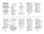
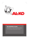
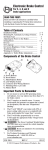
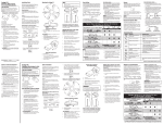
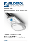
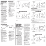
®
VOYAGER ELECTRONIC BRAKE CONTROL
Instructions for Voyager® Brake Control
For 2, 4, 6* and 8* brake applications
READ THIS FIRST:
Read and follow all instructions carefully
before installing or operating the Brake
Control. Keep these instructions with the
Brake Control for future reference.
Installation Guide
Leveling the Sensor
WARNING The Brake Control must be
mounted from -20 degrees nose down to 70
degrees nose up. (See Below.) Failure to install
brake control within these constraints may
cause your control to become inoperable.
After the brake control has been securely mounted
the level adjustment must be set.
NOTE:
1.
70°
Components of the Brake Control
2.
D
A
E
1.
C
0°
B
A.
B.
C.
D.
E.
Connect trailer to tow vehicle, Bi-Colored
Light should glow GREEN.
Set power knob to maximum by fully
rotating clockwise.
Depress tow vehicle’s brake pedal and hold.
Rotate the Level Knob counter-clockwise
(towards the back of the control) until the
Bi-Colored Light starts to change colors
from GREEN to RED.
Carefully rotate the Level Knob clockwise
(towards the front of the control) until
a shade of ORANGE is visible.
Bi-Colored Light should show:
• DIM ORANGE for a typical setting.
• BRIGHT ORANGE for an aggressive setting.
• DIM RED for a more aggressive setting.
2.
3.
4.
-20°
Traditional Bracket Mount
Power Knob
Manual Slide Knob
Bracket Mounting Holes
Bi-Colored Light
Level Knob
A
B
5.
Important Facts to Remember
1.
Do not mount or activate RF generating items
(cell phones, two way radios) near (less than
12") the Brake Control.
2. CAUTION Reversing the connection to a
breakaway battery on the trailer will destroy
the Brake Control.
3. CAUTION Disconnect trailer plug from the
tow vehicle prior to testing a breakaway
switch or you may destroy the Brake Control.
4. The light is:
• GREEN when trailer is connected.
• RED when brake pedal or manual is
activated and trailer is connected.
5. The GREEN light draws 5 milliamperes of
current from tow vehicle. It would take over
10,000 hours to drain the tow vehicle battery.
6. WARNING The level adjustment is
CRITICAL. The level adjustment
determines whether automatic braking
response is delayed or aggressive.
7. This brake control is activated by inertia.
It senses deceleration and generates an
output that reflects the inertia sensed.
In a stationary state, the brake control
will not apply the trailer brakes unless
the Manual Slide Knob is actuated.
8. WARNING The Gross Combined Weight
Rating (GCWR) must never exceed the
vehicle manufacturers recommendation.
9. This control specfically designed for use
with electric trailer brakes.
10. For Technical Assistance and Warranty
Information call: 1-888-785-5832 or
www.tekonsha.com
1
A. Mounting Bracket
B. #6 x 3/8” Screws
1.
2.
3.
4.
CAUTION Drilling or use of longer
screws may damage unit.
Securely mount bracket to a solid surface.
Insert supplied #6 x 3/8” screws on each
side into the mounting holes.
Adjust control to desired position and
tighten screws until snug.
NOTE:
1. Front of the Voyager must be horizontal,
see below.
2. The Voyager must be parallel to direction
of travel, see below.
Correct
Incorrect
WARNING This brake control is
activated by inertia and requires the
level to be set properly, or the braking
response will be too harsh or ineffective.
To properly level the sensor, the trailer
and tow vehicle must be parked on
a level surface and trailer must be
connected to tow vehicle.
NOTE: Range of adjustment for the level
knob from DIM ORANGE to DIM RED
is 20 degrees of rotation.
6.
Release brake pedal.
NOTE: When the brake control is leveled
properly there will be very little current
flowing through the brake magnets in a
static state with the foot pedal depressed.
The brake magnets will hum when there is
current flowing through them. Anytime the
Bi-Colored Light shows any color other than
GREEN, there is current flowing through
the brake magnets.
Adjusting the Power to the
Trailer Brakes
Once the control has been installed and properly
leveled, it is necessary to set the power needed
to stop the trailer during a braking event.
1.
Connect trailer to tow vehicle.
2.
Set Power Knob to the 12 o’clock position.
3.
Drive tow vehicle and trailer on a dry level
paved surface at 25 mph and apply manual
slide knob.
✓ If trailer brakes lock up:
❑ Turn power down using power knob.
(Rotate power knob toward the 8 o’clock
position, counter-clockwise.)
D i r e c t i o n o f Tr ave l
D i r e c t i o n o f Tr ave l
✓
If braking was not sufficient:
❑ Turn power up using power knob.
(Rotate power knob toward the 5 o’clock
position, clockwise.)
Technical Assistance Call Toll-Free: 1-888-785-5832 or www.tekonsha.com
P/N 3840 REV J 08/03
®
VOYAGER ELECTRONIC BRAKE CONTROL
Instructions for Voyager® Brake Control (CONTINUED)
4.
5.
Repeat Step (3) until power has been set
to a point just below wheel lock up or at
a sufficient force as to achieve maximum
braking power.
Using the brake pedal, make a few low
speed stops to check the Power and Level
adjustments. The automatic response
(brake pedal) is initiated and terminated
via the stoplight switch. When the brake
pedal is released, trailer braking will cease.
NOTE:
1.
2.
Fine Tuning
Now that the Power has been set, it is time
to fine tune the level setting for the majority
of the stopping that you will be doing.
1.
Make several slow (25 MPH) stops as
if coming up to a stop sign and take
notice of how the trailer brakes respond:
✓ Brakes Grab Too Much
❑ You have an Aggressive Setting:
To correct this condition rotate level
knob clockwise, toward you, see below.
✓ Trailer Tending to Push Tow Vehicle
❑ You have a Delayed Setting:
To correct this condition rotate level
knob counter-clockwise, away from
you, see below.
2.
Repeat until desired trailer braking
is achieved.
3.
Always warm the trailer's brakes before
setting the power. Warm trailer brakes tend to
be more responsive than cold brakes. To warm
trailer brakes, drive a short distance (1/4 mile)
at 45 MPH with manual lever engaged enough
to cause trailer braking at a low level.
WARNING The power should never be set
high enough to cause trailer brakes to lock up.
Skidding trailer wheels can cause loss of
directional stability of trailer and tow vehicle.
The power may need to be adjusted for
different load weights and road conditions.
A.
B.
C.
Delayed
Normal
Aggressive
C
6.
Situation
Tow vehicle connected to trailer,
NO GREEN light.
Tow vehicle connected to trailer, light is
GREEN. When Manual Slide Knob is activated:
A. No RED light.
C. Light glows dim RED and gets brighter
as POWER Knob is decreased.
A
5.
Not all trailer brakes will lock up due to
various conditions. However, inability to lock
up the brakes generally indicates the need for
an inspection to determine the cause.
When the power is set correctly you should
feel unified braking between the trailer and
tow vehicle.
When in doubt of the proper setting procedures
review the above steps starting at LEVELING
THE SENSOR through FINE TUNING or
consult your tow card included with your
brake control.
Troubleshooting Chart
B. Light is dim RED or flashing RED.
B
4.
Probable Cause
1. Corrosion on trailer plug contact.
2. Loose POWER or GROUND connection.
1. POWER set at or near minimum.
2. Short on BRAKE line (BLUE wire).
3. BLACK & WHITE wires reversed,
control destroyed.
4. 12 volts from external source on BRAKE
line (BLUE wire).
1. Open on GROUND line (WHITE wire).
2. Short on BRAKE line (BLUE wire).
1. Short on BRAKE line (BLUE wire).
2. Defective brake magnets.
Braking with foot pedal is too aggressive.
1. Sensor set too aggressive,
see LEVELING SENSOR.
2. Power set too high.
Braking is delayed for extended period.
1. Sensor set improperly,
see LEVELING SENSOR.
2. Power set too low.
Tow vehicle connected to trailer, brake
pedal depressed:
A. No RED light.
1. Vehicle not moving, need to be moving
for brakes to apply.
2. No signal from brake light, test voltage
on RED wire.
3. Sensor set improperly,
see LEVELING SENSOR.
4. Bad connection on RED wire.
5. Blown stoplight fuse.
Appendix A: Trailer Brake Adjustment**
Brakes should be adjusted after the first 200 miles of
operation when the brake shoes and drums have “seated”
and at 3000 mile intervals, or as use and performance
requires. The brakes should be adjusted in the
following manner:
1. Jack up trailer and secure on adequate capacity
jack stands. Follow trailer manufacturers
recommendations for lifting and supporting the
unit. Check that the wheel and drum rotate freely.
WARNING Do not lift or support trailer on any
part of the axle or the suspension system.
2. Remove the adjusting hole cover from the adjusting
slot on the bottom of the brake backing plate.
3. With a screwdriver or standard adjusting tool, rotate
the starwheel of the adjuster assembly to expand the
brake shoes. Adjust the brake shoes out until the
pressure of the linings against the drum makes the
wheel very difficult to turn.
Note: With drop spindle axles, a modified adjusting
tool with about an 80 degree angle should be used.
4. Then rotate the starwheel in the opposite direction
until the wheel turns freely with a slight lining drag.
5. Replace the adjusting hole cover and lower the
wheel to the ground.
6. Repeat the above procedure on all brakes.
WARNING Never crawl under your trailer unless
it is resting on properly placed jack stands.
Follow the trailer manufacturers recommendations
for lifting and supporting the unit. Do not lift or place
supports on any part of the suspension system.
**Note: Trailer Brake Adjustment procedures courtesy
Dexter Axle.
2
Technical Assistance Call Toll-Free: 1-888-785-5832 or www.tekonsha.com
P/N 3840 REV J 08/03