1
User’s Guide
Part Number: E3631-90002
April 2000.
For Safety information, Warranties, and Regulatory information,
see the pages behind the Index.
© Copyright Agilent Technologies, Inc. 2000
All Rights Reserved.
Agilent E3631A
Triple Output
DC Power Supply
Remote Interface Reference
• SCPI Command Summary, page 65
è
• Simplified Programming Overview, page 70
• Using the APPLy Command, page 73
• Output Setting and Operation Commands, page 74
• Triggering Commands, page 79
• System-Related Commands, page 82
• Calibration Commands, page 85
• RS-232 Interface Commands, page 87
• The SCPI Status Registers, page 88
• Status Reporting Commands, page 98
è
• An Introduction to the SCPI Language, page 102
• Halting an Output in Progress, page 107
• SCPI Conformance Information, page 108
• IEEE-488 Conformance Information, page 111
If you are a first-time user of the SCPI language, you may want to refer to
these sections to become familiar with the language before attempting to
program the power supply.
64
Chapter 4 Remote Interface Reference
SCPI Command Summary
SCPI Command Summary
This section summarizes the SCPI (Standard Commands for Programmable
Instruments) commands available to program the power supply over the
remote interface. Refer to the later sections in this chapter for more
complete details on each command.
Throughout this manual, the following conventions are used for SCPI
command syntax.
• Square brackets ([ ]) indicate optional keywords or parameters.
• Braces ({ }) enclose parameters within a command string.
• Triangle brackets (< >) indicate that you must substitute a value or a code
for the enclosed parameter.
• A vertical bar ( | ) separates one of two or more alternative parameters.
4
First-time SCPI users, see page 102
65
Chapter 4 Remote Interface Reference
SCPI Command Summary
Output Setting and Operation Commands
APPLy
{P6V|P25V|N25V}[,{<voltage>|DEF|MIN|MAX}[,{<current>|DEF|MIN|MAX}]]
APPLy? [{P6V|P25V|N25V}]
INSTrument
[:SELect] {P6V|P25V|N25V}
[:SELect]?
:NSELect {1|2|3}
:NSELect?
:COUPle[:TRIGger] {ALL|NONE|<list>}
:COUPle[:TRIGger]?
MEASure
:CURRent[:DC]? [{P6V|P25V|N25V}]
[:VOLTage][:DC]? [{P6V|P25V|N25V}]
OUTPut
[:STATe] {OFF|ON}
[:STATe]?
:TRACk[:STATe] {OFF|ON}
:TRACk[:STATe]?
[SOURce:]
CURRent[:LEVel][:IMMediate][:AMPLitude] {<current>[MIN|MAX}
CURRent[:LEVel][:IMMediate][:AMPLitude]?[MIN|MAX]
CURRent[:LEVel]:TRIGgered[:AMPLitude]
{<current>[MIN|MAX}
CURRent[:LEVel]:TRIGgered[:AMPLitude]? [MIN|MAX]
VOLTage[:LEVel][:IMMediate][:AMPLitude] {<voltage>|MIN|MAX}
VOLTage[:LEVel][:IMMediate][:AMPLitude]?[MIN|MAX]
VOLTage[:LEVel]:TRIGgered[:AMPLitude]
{<voltage>[MIN|MAX}
VOLTage[:LEVel]:TRIGgered[:AMPLitude]? [MIN|MAX]
Triggering Commands
INITiate [:IMMediate]
TRIGger[:SEQuence]
:DELay {<seconds>|MIN|MAX}
:DELay?
:SOURce {BUS|IMM}
:SOURce?
*TRG
66
Chapter 4 Remote Interface Reference
SCPI Command Summary
System-Related Commands
DISPlay[:WINDow]
[:STATe] {OFF|ON}
[:STATe]?
:TEXT[:DATA] <quoted string>
:TEXT[:DATA]?
:TEXT:CLEar
SYSTem
:BEEPer[:IMMediate]
:ERRor?
:VERSion?
*IDN?
*RST
4
*TST?
*SAV {1|2|3}
*RCL {1|2|3}
Calibration Commands
CALibration
:COUNt?
:CURRent[:DATA] <numeric value>
:CURRent:LEVel {MIN|MAX}
:SECure:CODE <new code>
:SECure:STATe {OFF|ON}, <code>
:SECure:STATe?
:STRing <quoted string>
:STRing?
:VOLTage[:DATA] <numeric value>
:VOLTage:LEVel {MIN|MAX}
67
Chapter 4 Remote Interface Reference
SCPI Command Summary
Status Reporting Commands
STATus:QUEStionable
[:EVENt]?
:ENABle <enable value>
:ENABle?
:INSTrument[:EVENt]?
:INSTrument:ENABle <enable value>
:INSTrument:ENABle?
:INSTrument:ISUMmary<n>[:EVENt]?
:INSTrument:ISUMmary<n>:CONDition?
:INSTrument:ISUMmary<n>:ENABle <enable value>
:INSTrument:ISUMmary<n>:ENABle?
SYSTem:ERRor?
*CLS
*ESE <enable value>
*ESE?
*ESR?
*OPC
*OPC?
*PSC {0|1}
*PSC?
*SRE <enable value>
*SRE?
*STB?
*WAI
RS-232 Interface Commands
SYSTem
:LOCal
:REMote
:RWLock
68
Chapter 4 Remote Interface Reference
SCPI Command Summary
IEEE-488.2 Common Commands
*CLS
*ESE <enable value>
*ESE?
*ESR?
*IDN?
*OPC
*OPC?
*PSC {0|1}
*PSC?
*RST
*SAV {1|2|3}
4
*RCL {1|2|3}
*SRE <enable value>
*SRE?
*STB?
*TRG
*TST?
*WAI
69
Chapter 4 Remote Interface Reference
Simplified Programming Overview
Simplified Programming Overview
First-time
SCPI users,
see page 102
This section gives an overview of the basic techniques used to program the
power supply over the remote interface. This section is only an overview
and does not give all of the details you will need to write your own
application programs. Refer to the remainder of this chapter and also
chapter 6, Application Programs, for more details and examples. Also refer
to the programming reference manual that came with your computer for
details on outputting command strings and entering data.
Using the APPLy Command
The APPLy command provides the most straightforward method to
program the power supply over the remote interface. For example, the
following statement executed from your computer will set the +6V supply to
an output of 3 V rated at 1 A:
"APPL P6V, 3.0, 1.0"
Using the Low-Level Commands
Although the APPLy command provides the most straightforward method to
program the power supply, the low-level commands give you more flexibility
to change individual parameters. For example, the following statements
executed from your computer will set the +6V supply to an output of 3 V
rated at 1 A:
70
"INST P6V"
Select +6V output
"VOLT 3.0"
Set output voltage to 3.0 V
"CURR 1.0"
Set output current to 1.0 A
Chapter 4 Remote Interface Reference
Simplified Programming Overview
Reading a Query Response
Only the query commands (commands that end with “?”) will instruct the
power supply to send a response message. Queries return either output
values or internal instrument settings. For example, the following statements
executed from your computer will read the power supply's error queue and
print the most recent error:
dimension statement
Dimension string array (80 elements)
"SYST:ERR?"
Read error queu
bus enter statement
Enter error string into computer
print statement
Print error string
Selecting a Trigger Source
The power supply will accept a “bus” (software) trigger or an immediate
internal trigger as a trigger source. By default, the “BUS” trigger source is
selected. If you want the power supply to use an immediate internal trigger,
you must select “IMMediate”. For example, the following statements
executed from your computer will set the +6V supply to an output of 3 V/1 A
immediately:
"INST P6V"
Select the +6V output
"VOLT:TRIG 3.0"
Set the triggered voltage level to 3.0 V
"CURR:TRIG 1.0"
Set the triggered current level to 1.0 A
"TRIG:SOUR IMM"
Select the immediate trigger as a source
"INIT"
Cause the trigger system to initiate
71
4
Chapter 4 Remote Interface Reference
Simplified Programming Overview
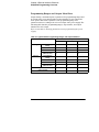
Programming Ranges and Output Identifiers
Output setting commands require a parameter for programming ranges and
an output name or an output number as the identifier of each output and
most queries will return a parameter. The programming range for a
parameter varies according to the selected output of the power supply. The
following table lists the programming ranges, output names, and output
numbers for each output.
Refer to this table to identify parameters when programming the power
supply.
Table 4-1. Agilent E3631A Programming Ranges and Output Identifiers
Output
+6V output
Voltage
Programming
Range
72
0 to +25.75 V
-25V output
0 to -25.75 V
MAX value
6.18 V
25.75 V
-25.75 V
MIN value
0V
0V
0V
0V
0V
0V
0 to 5.15 A
0 to 1.03 A
0 to 1.03 A
*RST value
(DEFault value)
Current
0 to 6.18 V
+25V output
Programming
Range
MAX value
5.15 A
1.03 A
1.03 A
MIN value
0A
0A
0A
*RST value
(DEFault value)
5A
1A
1A
Output identifier
P6V
P25V
N25V
Output number
1
2
3
Chapter 4 Remote Interface Reference
Using the APPLy Command
Using the APPLy Command
The APPLy command provides the most straightforward method to program
the power supply over the remote interface. You can select the specific
output, output voltage, and output current all in one command.
APPLy
{P6V | P25V | N25V}[,{<voltage>| DEF | MIN | MAX}[,{<current>| DEF | MIN | MAX}]]
This command is combination of INSTrument:SELect, [SOURce:]
VOLTage, and [SOURce:]CURRent commands. The values of voltage and
the current of the specified output are changed as soon as the command is
executed.
You can identify each output by the output name (P6V, P25V or N25V) as
described in Table 4-1. For the voltage and current parameters of the APPLy
command, the ranges depend on the output currently selected. You can
substitute “MINimum”, “MAXimum”, or “DEFault” in place of a specific
value for the voltage and current parameters. MIN selects the lowest voltage
and current values allowed for the selected output. MAX selects the highest
voltage and current values allowed. The default voltage values are 0 volts
for all outputs. The default current values are 5 A for +6V output and 1 A for
±25V outputs. The default voltage and current values are exactly the same as
the *RST values. See Table 4-1 for details of parameters.
If you specify only one value for the parameter, the power supply regards it
as voltage setting value. If you do not specify any value for the parameter,
the APPLy command only selects the output specified and acts as the
INSTrument command.
APPLy? [{P6V | P25V | N25V}]
This command queries the power supply's present voltage and current
values for each output and returns a quoted string. The voltage and current
are returned in sequence as shown in the sample string below (the quotation
marks are returned as part of the string). If any output identifier is not
specified, the voltage and the current of the currently selected output are
returned.
"5.000000,1.000000"
In the above string, the first number 5.000000 is the voltage limit value and
the second number 1.000000 is the current limit value for the specified
output.
73
4
Chapter 4 Remote Interface Reference
Output Setting and Operation Commands
Output Setting and Operation Commands
This section describes the low-level commands used to program the power
supply. Although the APPLy command provides the most straightforward
method to program the power supply, the low-level commands give you
more flexibility to change individual parameters.
See page 102 for programming ranges, output identifiers, and MIN / MAX
values in the following commands.
Output Selection Commands
INSTrument[:SELect] {P6V | P25V | N25V}
This command selects the output to be programmed among three outputs by
the output identifier. The outputs of the power supply are considered three
logical instruments. The INSTrument command provides a mechanism to
identify and select an output. When one output is selected, the other outputs
are unavailable for programming until selected. The commands which are
affected by the INSTrument command are output setting commands
(SOURce), measurement commands (MEASure), and calibration commands
(CALibration). “P6V” is the identifier for +6V output, “P25V” is for +25V
output and “N25V” is for -25V output.
INSTrument[:SELect]?
This query returns the currently selected output by the INSTrument
[:SELect] or INSTrument:NSELect command. The returned
parameter is “P6V”, “P25V”, or “N25V”.
INSTrument:NSELect {1 | 2 | 3}
This command selects the output to be programmed among three outputs by
a numeric value instead of the output identifier used in the INSTrument
[:SELect] command. “1” selects +6V output, “2” selects +25V output, and
“3” selects -25V output.
INSTrument:NSELect?
This query returns the currently selected output by the INSTrument
:NSELect or INSTrument[:SELect] command. The returned parameter
is “1” for +6V output, “2” for +25V output or “3” for -25V output.
74
Chapter 4 Remote Interface Reference
Output Setting and Operation Commands
INSTrument:COUPle[:TRIGger] {ALL | NONE |<list>}
This command defines a coupling between various logical outputs of the
power supply. The couple command consists of an optional subsystem node
followed by a single parameter. The only valid parameter for the optional
subsystem node is TRIGger subsystem. If no node follows the couple
command, TRIGger subsystem is assumed to be coupled.
The parameter indicates to which logical outputs the specified coupling is
to apply. “ALL” indicates that specified coupling is to apply to all outputs.
“NONE” indicates that specified coupling is to be removed. A list of outputs
specifies a particular set of logical outputs to be coupled. At *RST, all
outputs are uncoupled. Notice that TRACk must be off before the ±25V
supplies can be coupled.
INST:COUP
Example (1)
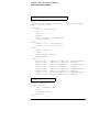
The following program segment shows how to use the INSTrument:
COUPle command to couple two outputs between the +6V and the +25V
outputs with voltage and current triggered levels. The power supply is set
to the newly programmed values as set by the VOLTage:TRIGgered and
CURRent:TRIGgered commands.
"INST:SEL P6V"
"VOLT:TRIG 5"
"CURR:TRIG 3"
"INST:SEL P25V"
"VOLT:TRIG 20"
"CURR:TRIG 0.5"
"INST:COUP P6V,P25V"
"TRIG:SOUR IMM"
"INIT"
Note
4
Select the +6V output
Set triggered level to 5 V
Set triggered level to 3 A
Select the +25V output
Set triggered level to 20 V
Set triggered level to 0.5 A
Couple the +6V and +25V supply
Set trigger to immediate
Trigger the power supply to
output the trigger values for
the +6V and the +25V supplies
If you select the bus trigger source in the above program (see page 79 for
the detailed information), you must send the *TRG or Group Execute
Trigger (GET) command to start the trigger action after sending the
INITiate command.
75
Chapter 4 Remote Interface Reference
Output Setting and Operation Commands
INSTrument:COUPle[:TRIGger]?
This query returns the currently coupled output. Returns “ALL”, “NONE”, or
a list. If any output is not coupled, “NONE” is returned. If all of three
outputs are coupled, “ALL” is returned. If a list of outputs is coupled, the list
is returned.
Measurement Commands
MEASure:CURRent[:DC]? [{P6V | P25V | N25V}]
This command queries the current measured at the output terminals of the
power supply. The physical outputs of measurement are specified by the
output identifier. If any output identifier is not specified, the current of the
currently selected output is returned.
MEASure[:VOLTage][:DC]? [{P6V | P25V | N25V}]
This command queries the voltage measured at the output terminals of the
power supply. If any output identifier is not specified, the voltage of the
currently selected output is returned.
76
Chapter 4 Remote Interface Reference
Output Setting and Operation Commands
Output On/Off and Tracking Operation Commands
OUTPut[:STATe] {OFF | ON}
This command enables or disables all three outputs of the power supply. The
state of the disabled outputs is a condition of less than 0.6 volts of opposite
polarity with no load and less than 60 mA of opposite direction with a short
circuit. At *RST, the output state is off.
OUTPut[:STATe]?
This command queries the output state of the power supply. The returned
value is “0” (OFF) or “1” (ON).
OUTPut:TRACk[:STATe] {OFF | ON}
This command enables or disables the power supply to operate in the track
mode. When the track mode is first enabled, the -25V supply will be set to
the same voltage level as the +25V supply. Once enabled, any change of the
programmed voltage level in either +25V supply or -25V supply will be
reflected in the other supply. The TRACk OFF command returns the power
supply to the non-track mode. The ±25V supplies must not be coupled to
enable “Track”. At *RST, the track mode is disabled.
4
OUTPut:TRACk[:STATe]?
This command queries the track mode state of the power supply. The
returned value is “0” (OFF) or “1” (ON).
Output Setting Commands
[SOURce:]CURRent[:LEVel][:IMMediate][:AMPLitude]
{<current>|MINimum | MAXimum}
This command directly programs the immediate current level of the power
supply. The immediate level is the current limit value of the output selected
with the INSTrument command.
[SOURce:]CURRent[:LEVel][:IMMediate][:AMPLitude]?
[MINimum | MAXimum]
This query returns the presently programmed current limit level of the
selected output. CURRent? MAXimum and CURRent? MINimum return
the maximum and minimum programmable current levels of the selected
output.
77
Chapter 4 Remote Interface Reference
Output Setting and Operation Commands
[SOURce:]CURRent[:LEVel]:TRIGgered[:AMPLitude]
{<current>| MINimum | MAXimum}
This command programs the pending triggered current level of the power
supply. The pending triggered current level is a stored value that is
transferred to the output terminals when a trigger occurs. A pending
triggered level is not affected by subsequent CURRent commands.
[SOURce:]CURRent[:LEVel]:TRIGgered[:AMPLitude]?
[MINimum | MAXimum]
This query returns the presently programmed triggered current level. If no
triggered level is programmed, the CURRent level is returned. CURRent
:TRIGgered? MAXimum and CURRent:TRIGgered? MINimum return the
maximum and minimum programmable triggered current levels.
VOLTage[:LEVel][:IMMediate][:AMPLitude]
{<voltage>| MINimum | MAXimum}
This command directly programs the immediate voltage level of the power
supply. The immediate level is the voltage limit value of the selected output
with the INSTrument command.
[SOURce:]VOLTage[:LEVel][:IMMediate][:AMPLitude]?
[MINimum | MAXimum]
This query returns the presently programmed voltage limit level of the
selected output. VOLTage? MAXimum and VOLTage? MINimum return
the maximum and minimum programmable voltage levels of the selected
output.
[SOURce:]VOLTage[:LEVel]:TRIGgered[:AMPLitude]
{<voltage>| MINimum | MAXimum}
This command programs the pending triggered voltage level of the power
supply. The pending triggered voltage level is a stored value that is
transferred to the output terminals when a trigger occurs. A pending
triggered level is not affected by subsequent VOLTage commands.
[SOURce:]VOLTage[:LEVel]:TRIGgered[:AMPLitude]?
[MINimum | MAXimum]
This query returns the presently programmed triggered voltage level. If no
triggered level is programmed, the VOLTage level is returned. VOLTage
:TRIGgered? MAXimum and VOLTage:TRIGgered? MINimum return
the maximum and minimum programmable triggered voltage levels.
78
Chapter 4 Remote Interface Reference
Triggering Commands
Triggering Commands
The power supply's triggering system allows a change in voltage and current
when receiving a trigger, to select a trigger source, and to insert a trigger.
Triggering the power supply is a multi-step process.
• First, you must select an output with the INSTrument:SELect
command and then configure the power supply for the triggered output
level by using CURRent:TRIGgered and VOLTage:TRIGgered
commands.
• Then, you must specify the source from which the power supply will
accept the trigger. The power supply will accept a bus (software) trigger
or an immediate trigger from the remote interface.
• Then, you can set the time delay between the detection of the trigger on
the specified trigger source and the start of any corresponding output
change. Notice that the time delay is valid for only the bus trigger
source.
4
• Finally, you must provide an INITiate[:IMMediate]command. If the
IMMediate source is selected, the selected output is set to the triggered
level immediately. But if the trigger source is the bus, the power supply is
set to the triggered level after receiving the Group Execute Trigger (GET)
or *TRG command.
Trigger Source Choices
You must specify the source from which the power supply will accept a
trigger. The trigger is stored in volatile memory; the source is set to bus
when the power supply has been off or after a remote interface reset.
Bus (Software) Triggering
• To select the bus trigger source, send the following command.
TRIGger:SOURce BUS
• To trigger the power supply from the remote interface (GPIB or RS-232)
after selecting the bus source, send the *TRG (trigger) command. When
the *TRG is sent, the trigger action starts after the specified time delay if
any delay is given.
79
Chapter 4 Remote Interface Reference
Triggering Commands
• You can also trigger the power supply from the GPIB interface by
sending the IEEE-488 Group Execute Trigger (GET) message. The
following statement shows how to send a GET from a Agilent Technologies
controller.
TRIGGER 705 (group execute trigger)
• To ensure synchronization when the bus source is selected, send the
*WAI (wait) command. When the *WAI command is executed, the power
supply waits for all pending operations to complete before executing any
additional commands. For example, the following command string
guarantees that the first trigger is accepted and is executed before the
second trigger is recognized.
TRIG:SOUR BUS;*TRG;*WAI;*TRG;*WAI
• You can use the *OPC? (operation complete query) command or the
*OPC (operation complete) command to signal when the operation is
complete. The *OPC? command returns “1” to the output buffer when the
operation is complete. The *OPC command sets the “OPC” bit (bit 0) in
the Standard Event register when the operation is complete.
Immediate Triggering
• To select the immediate trigger source, send the following command.
TRIGger:SOURce IMM
• When the IMMediate is selected as a trigger source, an INITiate
command immediately transfers the VOLTage:TRIGgered
[:AMPLitude] and CURRent:TRIGgered[:AMPLitude]values to
VOLTage[:LEVel][:IMMediate][:AMPLitude] and CURRent
[:LEVel][:IMMediate][:AMPLitude]values. Any delay is ignored.
80
Chapter 4 Remote Interface Reference
Triggering Commands
Triggering Commands
INITiate[:IMMediate]
This command causes the trigger system to initiate. This command
completes one full trigger cycle when the trigger source is an immediate and
initiates the trigger subsystem when the trigger source is bus.
TRIGger[:SEQuence]:DELay{<seconds>| MINimum | MAXimum}
This command sets the time delay between the detection of an event on the
specified trigger source and the start of any corresponding trigger action on
the power supply output. Select from 0 to 3600 seconds. MIN = 0 seconds.
MAX = 3600 seconds. At *RST , this value is set to 0 seconds.
TRIGger[:SEQuence]:DELay?
This command queries the trigger delay.
TRIGger[:SEQuence]:SOURce {BUS | IMMediate}
4
This command selects the source from which the power supply will accept
a trigger. The power supply will accept a bus (software) trigger or an internal
immediate trigger. At *RST, the bus trigger source is selected.
TRIGger[:SEQuence]:SOURce?
This command queries the present trigger source. Returns “BUS” or “IMM”.
*TRG
This command generates a trigger to the trigger subsystem that has selected a
bus (software) trigger as its source (TRIGger:SOURce BUS). The
command has the same effect as the Group Execute Trigger (GET)
command. For RS-232 operation, make sure the power supply is in the
remote interface mode by sending the SYSTem:REMote command first.
81
Chapter 4 Remote Interface Reference
System-Related Commands
System-Related Commands
DISPlay[:WINDow][:STATe] {OFF | ON}
This command turns the front-panel display off or on. When the display is
turned off, outputs are not sent to the display and all annunciators are disabled
except the ERROR annunciator.
The display state is automatically turned on when you return to the local
mode. Press the Local key to return to the local state from the remote
interface.
DISPlay[:WINDow][:STATe]?
This command queries the front-panel display setting. Returns “0” (OFF) or
“1” (ON).
DISPlay[:WINDow]:TEXT[:DATA] <quoted string>
This command displays a message on the front panel. The power supply will
display up to 12 characters in a message; any additional characters are
truncated. Commas, periods, and semicolons share a display space with the
preceding character, and are not considered individual characters.
DISPlay[:WINDow]:TEXT[:DATA]?
This command queries the message sent to the front panel and returns a
quoted string.
DISPlay[:WINDow]:TEXT:CLEar
This command clears the message displayed on the front panel.
SYSTem:BEEPer[:IMMediate]
This command issues a single beep immediately.
82
Chapter 4 Remote Interface Reference
System-Related Commands
SYSTem:ERRor?
This command queries the power supply's error queue. When the front-panel
ERROR annunciator turns on, one or more command syntax or hardware
errors have been detected. Up to 20 errors can be stored in the error queue.
See “Error Messages” in chapter 5.
• Errors are retrieved in first-in-first-out (FIFO) order. The first error
returned is the first error that was stored. When you have read all errors
from the queue, the ERROR annunciator turns off. The power supply
beeps once each time an error is generated.
• If more than 20 errors have occurred, the last error stored in the queue
(the most recent error) is replaced with -350, “Too many errors”. No
additional errors are stored until you remove errors from the queue. If no
errors have occurred when you read the error queue, the power supply
responds with +0, “No error”.
• The error queue is cleared when power has been off or after a *CLS
(clear status) command has been executed. The *RST (reset) command
does not clear the error queue.
4
SYSTem:VERSion?
This command queries the power supply to determine the present SCPI
version. The returned value is of a string in the form YYYY.V where the “Y’s”
represent the year of the version, and the “V” represents a version number for
that year (for example, 1995.0).
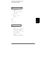
*IDN?
This query command reads the power supply's identification string. The
power supply returns four fields separated by commas. The first field is the
manufacturer's name, the second field is the model number, the third field is
not used (always “0”), and the fourth field is a revision code which contains
three numbers. The first number is the firmware revision number for the
main power supply processor; the second is for the input/output processor;
and the third is for the front-panel processor.
The command returns a string with the following format (be sure to
dimension a string variable with at least 40 characters):
HEWLETT-PACKARD,E3631A,0,X.X-X.X-X.X
83
Chapter 4 Remote Interface Reference
System-Related Commands
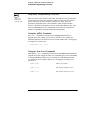
*RST
This command resets the power supply to its power-on state as follows:
Command
State
CURR[:LEV][:IMM]
CURR[:LEV]:TRIG
DISP[:STAT]
INST[:SEL]
INST:COUP
OUTP[:STAT]
OUTP:TRAC
TRIG:DEL
TRIG:SOUR
VOLT[:LEV][:IMM]
VOLT[:LEV]:TRIG
Output dependent value*
Output dependent value*
ON
P6V
NONE
OFF
OFF
0
BUS
0
0
*The reset operation sets the current of +6V output to 5 A and the current of
+25V and -25V outputs to 1 A.
*TST?
This query performs a complete self-test of the power supply. Returns “0” if
the self-test passes or “1” or any non-zero value if it fails. If the self-test fails,
an error message is also generated with additional information on why the
test failed.
*SAV { 1 | 2 | 3 }
This command stores the present state of the power supply to the specified
location in non-volatile memory. Three memory locations (numbered 1, 2
and 3) are available to store operating states of the power supply. The state
storage feature “remembers” the states or values of INST[:SEL],
VOLT[:IMM], CURR[:IMM], OUTP[:STAT], OUTP:TRAC, TRIG:SOUR, and
TRIG:DEL. To recall a stored state, you must use the same memory location
used previously to store the state.
*RCL {1 | 2 | 3 }
This command recalls a previously stored state. To recall a stored state, you
must use the same memory location used previously to store the state. You
recall *RST states or values of the power supply from a memory location
that was not previously specified as a storage location.
84