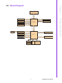
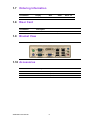
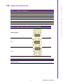
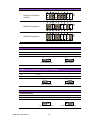
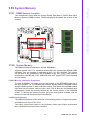
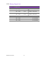
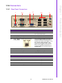
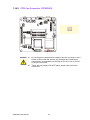
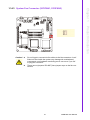
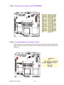
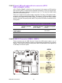
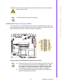
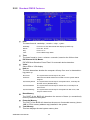
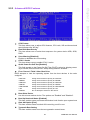
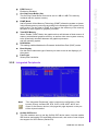
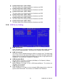
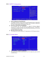
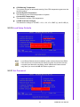
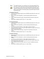
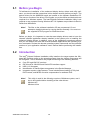
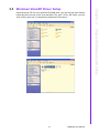
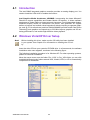
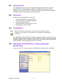
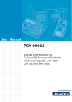
1
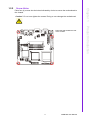
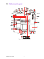
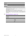
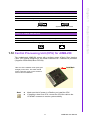
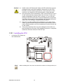
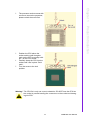
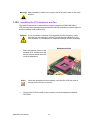
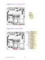
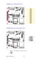
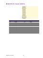
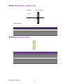
User Manual
AIMB-258
Intel® GM45 µFC-PGA 478
Core™2 Duo Mini ITX Motherboard
with VGA, DVI, LVDS, 6 COM, Dual GbE, 8 USB, 2 SATA II, PCIe x 16
Version June 2009
Data Modul AG - www.data-modul.com
Safety Information
Electrical safety
!
!
!
!
!
!
To prevent electrical shock hazard, disconnect the power cable from the electrical outlet before relocating the system.
When adding or removing devices to or from the system, ensure that the power
cables for the devices are unplugged before the signal cables are connected. If
possible, disconnect all power cables from the existing system before you add a
device.
Before connecting or removing signal cables from the motherboard, ensure that
all power cables are unplugged.
Seek professional assistance before using an adapter or extension cord. These
devices could interrupt the grounding circuit.
Make sure that your power supply is set to the correct voltage in your area. If
you are not sure about the voltage of the electrical outlet you are using, contact
your local power company.
If the power supply is broken, do not try to fix it by yourself. Contact a qualified
service technician or your retailer.
Operation safety
!
!
!
!
!
!
Before installing the motherboard and adding devices on it, carefully read all the
manuals that came with the package.
Before using the product, make sure all cables are correctly connected and the
power cables are not damaged. If you detect any damage, contact your dealer
immediately.
To avoid short circuits, keep paper clips, screws, and staples away from connectors, slots, sockets and circuitry.
Avoid dust, humidity, and temperature extremes. Do not place the product in
any area where it may become wet.
Place the product on a stable surface.
If you encounter technical problems with the product, contact a qualified service
technician or your retailer.
Caution! The symbol of the crossed out wheeled bin indicates that the product
(electrical and electronic equipment) should not be placed in municipal
waste. Check local regulations for disposal of electronic products.
AIMB-258 User Manual
Part No. 2006025801
Edition 2
Printed in Taiwan
June 2009
ii
Certifications
This device complies with the requirements in part 15 of the FCC rules: Operation is
subject to the following two conditions:
! This device may not cause harmful interference,
! This device must accept any interference received, including interference that
may cause undesired operation.
This equipment has been tested and found to comply with the limits for a Class A digital device, pursuant to Part 15 of the FCC Rules. These limits are designed to provide reasonable protection against harmful interference when the equipment is
operated in a commercial environment. This equipment generates, uses, and can
radiate radio frequency energy and, if not installed and used in accordance with the
instruction manual, may cause harmful interference to radio communications. Operation of this device in a residential area is likely to cause harmful interference in which
case the user will be required to correct the interference at his/her own expense. The
user is advised that any equipment changes or modifications not expressly approved
by the party responsible for compliance would void the compliance to FCC regulations and therefore, the user's authority to operate the equipment.
Caution! There is a danger of a new battery exploding if it is incorrectly installed.
Do not attempt to recharge, force open, or heat the battery. Replace the
battery only with the same or equivalent type recommended by the manufacturer. Discard used batteries according to the manufacturer's
instructions.
iii
AIMB-258 User Manual
Technical Support
If a problem arises with your system and no solution can be obtained from the user’s
manual, please contact your place of purchase or local distributor. Alternatively,
please try the following help resources for further guidance. Visit the Advantech website for FAQ, technical guide, BIOS updates, driver updates, and other information:
http://support.advantech.com.tw/Support/default.aspx
Packing List
Before you begin installing your single board, please make sure that the following
materials have been shipped:
! 1 x AIMB-258 Intel® µFC-PGA 478 Core 2 Duo Mini ITX Motherboard
! 2 x SATA HDD cable
! 2 x SATA Power cable
! 1 x Serial port cable 1 to 4
! 1 x I/O port bracket
! 1 x Startup manual
! 1 x Driver CD
! 1 x Warranty card
If any of the above items is damaged or missing, please contact your retailer.
AIMB-258 User Manual
iv
Contents
Chapter
1
Product Introduction ...........................1
1.1
1.2
Before You Proceed.................................................................................. 2
Motherboard Overview.............................................................................. 2
1.2.1 Placement Direction...................................................................... 2
1.2.2 Screw Holes.................................................................................. 3
Motherboard Layout .................................................................................. 4
Figure 1.1 Motherboard Layout ................................................... 4
Specifications ............................................................................................ 5
Operating System support list ................................................................... 6
Board Diagram .......................................................................................... 7
Ordering Information ................................................................................. 8
Riser Card ................................................................................................. 8
Bracket View ............................................................................................. 8
Accessories............................................................................................... 8
Layout Content List ................................................................................... 9
Table 1.1: Jumper Setting List..................................................... 9
Table 1.2: JSETCOM1: COM1/+5 V/+12 V Selection ................. 9
Table 1.3: JSETCOM2: COM2 RS232/422/485 Mode Selection 9
Table 1.4: CMOS1: Clear CMOS .............................................. 10
Table 1.5: J1:LCD Power 3.3 V/5.5 V Selection........................ 10
Table 1.6: PSON1: ATX, AT Mode Selection ............................ 10
Table 1.7: JWDT1: Watchdog Timer Output Option.................. 11
Table 1.8: JOBS: HW monitor ................................................... 11
Central Processing Unit (CPU) for AIMB-258 ......................................... 11
1.12.1 Installing the CPU ....................................................................... 12
1.12.2 Installing the CPU Heatsink and Fan .......................................... 14
1.12.3 Uninstalling the CPU Heatsink and Fan...................................... 16
System Memory ...................................................................................... 17
1.13.1 DIMM Sockets Location .............................................................. 17
1.13.2 System Memory .......................................................................... 17
1.13.3 Memory Support List................................................................... 18
Table 1.9: SODIMM DDR3 ........................................................ 18
Connectors.............................................................................................. 19
1.14.1 Rear Panel Connectors............................................................... 19
Table 1.10: Rear Panel Connectors ............................................ 19
Table 1.11: LEDs......................................................................... 19
1.14.2 CPU Fan Connector (CPUFAN1) ............................................... 20
1.14.3 System Fan Connector (SYSFAN1, SYSFAN2) ......................... 21
1.14.4 Serial Port Connector 3456 (COM3456)..................................... 22
1.14.5 Front Headphone Connector (HD1)............................................ 22
1.14.6 Front Panel Connector (JFP1/JFP2/JFP3) ................................. 23
1.14.7 ATX soft power switch (JFP1 / PWR_SW) ................................. 23
1.14.8 Reset (JFP1 / RESET)................................................................ 23
1.14.9 HDD LED (JFP2 / HDDLED)....................................................... 23
1.14.10External speaker (JFP2 / SPEAKER) ......................................... 23
1.14.11Power LED and keyboard lock connector
(JFP3 / PWR_LED&KEY LOCK) ................................................ 24
Table 1.12: ATX power supply LED status
(No support for AT power) ........................................ 24
1.14.12USB 2.0 Connector (USB56, USB78)......................................... 24
1.14.13ATX Power Connector (ATX1).................................................... 25
1.14.14LCD Inverter Connector (VP1).................................................... 26
1.14.15LVDS Connector (LVDS1) .......................................................... 26
1.14.16Digital I/O Connector (DIO_CN1)................................................ 27
1.3
1.4
1.5
1.6
1.7
1.8
1.9
1.10
1.11
1.12
1.13
1.14
v
AIMB-258 User Manual
1.14.17Serial ATA Connector 1 & 2 (SATA1, SATA2) ........................... 27
1.14.18PCIe x 16 Slot (PCIE X 16)......................................................... 28
1.14.19SPI Flash Connector(SPI_CN1) ................................................. 28
1.14.20Memory Connector Channel A/B(DIMM1/2) ............................... 29
1.14.21SPDIF1 out connector(SPDIF1) ................................................. 29
1.14.22CF connector .............................................................................. 30
Chapter
2
BIOS Operation ................................. 31
2.1
2.2
BIOS Introduction.................................................................................... 32
BIOS Setup ............................................................................................. 32
2.2.1 Main Menu .................................................................................. 33
2.2.2 Standard CMOS Features .......................................................... 34
2.2.3 Advanced BIOS Features ........................................................... 35
2.2.4 Advanced Chipset Features ....................................................... 36
2.2.5 Integrated Peripherals ................................................................ 37
2.2.6 USE Device Setting .................................................................... 39
2.2.7 Power Management Setup ......................................................... 40
2.2.8 PnP/PCI Configurations.............................................................. 42
2.2.9 PC Health Status ........................................................................ 42
2.2.10 Load Setup Defaults ................................................................... 43
2.2.11 Set Password.............................................................................. 43
3
Chipset Software Install Utility ........ 45
3.1
3.2
3.3
Before you Begin .................................................................................... 46
Introduction ............................................................................................. 46
Windows Vista/XP Driver Setup.............................................................. 47
4
VGA Setup ......................................... 49
4.1
4.2
Introduction ............................................................................................. 50
Windows Vista/XP Driver Setup.............................................................. 50
5
LAN Configuration ............................ 51
5.1
5.2
5.3
5.4
Introduction ............................................................................................. 52
Features.................................................................................................. 52
Installation............................................................................................... 52
Windows Vista/XP Driver Setup (Realtek RTL8111C)............................ 52
Appendix A
Programming the Watchdog Timer . 55
A.1
Programming the Watchdog Timer ......................................................... 56
A.1.1 Watchdog timer overview ........................................................... 56
A.1.2 Programming the Watchdog Timer............................................. 56
Table A.1: Watchdog Timer Registers....................................... 58
A.1.3 Example Program ....................................................................... 59
Appendix B
Pin Assignments............................... 63
B.1
USB Connector (USB56,USB78)............................................................ 64
Table B.1: USB5/USB6 Connector (USB56) ............................. 64
VGA Connector (VGA1A) ....................................................................... 64
Table B.2: VGA Connector (VGA1A)......................................... 64
Chapter
Chapter
Chapter
B.2
AIMB-258 User Manual
vi
B.3
B.4
B.5
B.6
B.7
B.8
B.9
B.10
B.11
B.12
B.13
B.14
B.15
B.16
B.17
B.18
B.19
DVI Connector (VGA1B) ......................................................................... 64
Table B.3: DVI Connector (VGA1B)........................................... 64
RS-232 Serial Port (COM1~COM2) ........................................................ 65
Table B.4: RS-232 Serial Port (COM1~COM2) ......................... 65
RS-232 Serial Port (COM3 ~ COM6) ...................................................... 66
Table B.5: RS-232 Serial Port (COM23).................................... 66
PS/2 Keyboard/ Mouse Connector (KBMS1) .......................................... 67
Table B.6: PS/2 Keyboard/ Mouse Connector (KBMS1) ........... 67
CPU Fan Power Connector (CPUFAN1) ................................................ 67
Table B.7: CPU Fan Power Connector (CPUFAN1).................. 67
Power LED & Keyboard Lock Connector (JFP3) .................................... 68
Table B.8: Power LED and Keylock Connector (JFP3) ............ 68
HDD LED and External Speaker Connector
(JFP2/HDD LED and SPEAKER)............................................................ 68
Table B.9: External Speaker Connector (JFP2/SPEAKER)....... 68
ATX Soft Power Switch and Reset Connector
(JFP1/ PWR-SW and RESET) ................................................................ 69
Table B.10:Audio Front Panel Connector (JFP1/ RESET) ......... 69
Audio Front Panel Connector (FPAUD1) ................................................ 69
Table B.11:Audio front panel connector (FPAUD1) .................... 69
GPIO Pin Header (GPIO1)...................................................................... 70
Table B.12:GPIO Pin Header (GPIO1) ....................................... 70
LVDS Connector (LVDS1) ...................................................................... 71
Table B.13:LVDS Connector (LVDS1)........................................ 71
LVDS Power Jumper (J1) ....................................................................... 72
Table B.14:LVDS Power Jumper (J1)......................................... 72
LVDS Invert (VP1)................................................................................... 72
Table B.15:LVDS Invert (VP1) .................................................... 72
System I/O Ports ..................................................................................... 73
Table B.16:System I/O Ports ...................................................... 73
DMA Channel Assignments .................................................................... 73
Table B.17:DMA Channel Assignments...................................... 73
Interrupt Assignments ............................................................................. 74
Table B.18:Interrupt Assignments............................................... 74
1st MB Memory Map ............................................................................... 74
Table B.19:1st MB Memory Map ................................................ 74
vii
AIMB-258 User Manual
AIMB-258 User Manual
viii
Chapter
1
1
Product Introduction
This chapter describes the main
board features and the new technologies it supports.
1.1 Before You Proceed
Take note of the following precautions before you install motherboard components or
change any motherboard settings.
Caution! !
!
!
!
!
Unplug the power cord from the wall socket before touching any
component.
Use a grounded wrist strap or touch a safely grounded object or a
metal object, such as the power supply case, before handling components to avoid damaging them due to static electricity
Hold components by the edges to avoid touching the ICs on them.
Whenever you uninstall any component, place it on a grounded
antistatic pad or in the bag that came with the component.
Before you install or remove any component, ensure that the ATX
power supply is switched off or the power cord is detached from the
power supply. Failure to do so may cause severe damage to the
motherboard, peripherals, and/or components.
1.2 Motherboard Overview
Before you install the motherboard, study the configuration of your chassis to ensure
that the motherboard fits into it. Refer to the chassis documentation before installing
the motherboard.
Warning! Make sure to unplug the power cord before installing or removing the
motherboard. Failure to do so can cause you physical injury and damage motherboard components.
1.2.1
Placement Direction
When installing the motherboard, make sure that you place it into the chassis in the
correct orientation. The edge with external ports goes to the rear part of the chassis.
AIMB-258 User Manual
2
Screw Holes
Place four (4) screws into the holes indicated by circles to secure the motherboard to
the chassis.
Caution! Do not over tighten the screws! Doing so can damage the motherboard.
3
AIMB-258 User Manual
Product Introduction
Place this side towards the rear
of the chassis.
Chapter 1
1.2.2
1.3 Motherboard Layout
1
2
2
1
4
3
1
2
3
6
PWR-SW RESET
4
8
5
7
3
4
SPEAKER
5
Figure 1.1 Motherboard Layout
AIMB-258 User Manual
4
CPU (45 nm
µFC-PGA 478)
Max. Speed
Processor Sys- Front Side Bus
tem
L2 Cache
Ethernet
SATA
SSD
Rear I/O
Internal
Connector
Watchdog
Timer
T9400 2.53 GHz
575 2.0 GHz
667/800/1066 MHz
667 MHz
6 MB
1 MB
GM45 + ICH9M
BIOS
Award 16 Mbit, SPI
PCI
-
PCIe x 16
4 GB/s per direction, 1 slot
Technology
DDR3 800/1066 MHz SDRAM
Max. Capacity
4 GB
Socket
2 x 204-pin SODIMM
Controller
Intel GM45 GMCH integrated Graphics Media Accelerator X4500
VRAM
Shared system memory up to 384 MB video memory
LVDS
Single channel 18/24-bit/Dual channel 36/48-bit LVDS
DVI-D
Yes (if DVI is used, PCIe x16 is automatically disable)
Dual Display
VGA + DVI; VGA + LVDS; DVI + LVDS
*Dual Display
Mode
Extended Mode, Clone Mode, Twin Mode
Interface
10/100/1000Base-T
Controller
GbE LAN1: Realtek RTL8111C; GbE LAN2: Realtek RTL8111C
Connector
RJ-45 x 2
Max Data Trans- 300 MB/s
fer Rate
Channel
2
Compact Flash
Compact Flash Supports compact flash type I/II
VGA
1
DVI
1
Ethernet
2
USB
4 (USB 2.0 compliant)
Serial
2 (1 of RS-232, 1 of RS-232/422/485)
PS/2
2 (1 x keyboard and 1 x mouse)
LVDS
1
USB
4 (USB 2.0 compliant)
Serial
4 (RS-232)
IDE
-
SATA
2
Audio
3 (Mic-in, Line-in, Line-out)
Compact Flash
1
Parallel
-
IrDA
-
FDD
-
DIO
16-bit General Purpose I/O for digital signal input/output
Output
Interrupt, system reset
Interval
Programmable 1 ~ 255 sec/ min
5
AIMB-258 User Manual
Product Introduction
Graphics
Intel Celeron M
Chipset
Expansion Slot Mini-PCI
Memory
Intel® Core™2 Duo
Chapter 1
1.4 Specifications
Power
Requirement
Environment
Power On
Temperature
Physical
Dimensions
Characteristics
5V
3.3 V
12 V
5 Vsb
-12 V
0.99 A
2.67 A
2.07 A
0.17 A
0.08 A
Operating
Non-Operating
0 ~ 60°C (32 ~ 140°F)
-20 ~ 70°C (-4 ~ 158°F)
170 mm x 170 mm (6.69’ x 6.69’)
*Dual Display Clone uses both display pipes to drive the same content at the same
resolution and color depth to two different displays. This configuration allows for different refresh rates on each display.
Dual Display Twin uses one of the display pipes to drive the same content, at the
same resolution, color depth, and refresh rates to two different displays.
Extended Desktop uses both display pipes to drive different content, at potentially
different resolutions, refresh rates, and color depths, to two different displays. This
configuration allows for a larger Windows desktop by using both displays as one
work surface.
1.5 Operating System support list
Operation System
AIMB-258
Windows Vista Ultimate edition
(32-bit/64-bit)
Support
Windows XP professional edition
(32-bit/64-bit)
Support
XP embedded
Support
Linux (Fedora)
Only OS installation and limited I/O functionality are
validated
QNX
Only OS installation and limited I/O functionality are
validated
WinCE 6.0
Require OEM BIOS. Please contact with Advantech
FAE
AIMB-258 User Manual
6
Chapter 1
1.6 Board Diagram
VGA
Channel A
DDR3 800/1066
Channel A
DDR3 800/1066
Dual Channel
LVDS
Intel GM45n
24-bit LVDS
GMCH
DVI
PCI3 x 16
JMB368
PCIe x 1
2 SATA ports
300MB/s
8 USB Ports
USB 2.0/1.1
Realtek ALC888
HD Audio
CF
IDE
2 GB/s bandwidth
Direct Media Interface
PCI3 x 16 slot
PCIe x 1
GbE-LAN1: Realtek 8111C
PCIe x 1
GbE-LAN2: Realtek 8111C
ICH9M
SM Bus
SPI
NXP 9555
BIOS
16-bit GPIO
7
LPC
Super IO
Winbond
W83627UHG
AIMB-258 User Manual
Product Introduction
CRT
MHz FSB
1066/800/667
Intel Socket 478
Core 2 Duo Processor
1.7 Ordering Information
Part Number
Display
GbE
SATA
Serial CF
AIMB-258G2-00A1E
VGA/ DVI/ LVDS
Dual
2
6
1.8 Riser Card
Part Number
Description
AIMB-R430P-03A1E
2U riser card with 3 PCI slot expansion
1.9 Bracket View
1.10 Accessories
Part Number
Description
1700003195
USB cable with four ports, 17.5 cm
1700002204
USB cable with four ports, 27 cm
1700002314
USB cable with four ports, 30.5 cm
AIMB-258 User Manual
8
1
Chapter 1
1.11 Layout Content List
Table 1.1: Jumper Setting List
Label
Function
JSETCOM1
COM1/+5 V/+12 V Selection
JSETCOM2
COM2 RS232/422/485 Mode Selection
CMOS1
Clear CMOS
LCD Power 3.3 V/5.5 V Selection
PSON1
ATX, AT Mode Selection
JWDT1
Watchdog Timer Output Option
JOBS1
Hardware Monitor
Product Introduction
J1
Table 1.2: JSETCOM1: COM1/+5 V/+12 V Selection
COM1 (Default)
+5 V
+12 V
Table 1.3: JSETCOM2: COM2 RS232/422/485 Mode Selection
Users can use JSETCOM2 to select among RS 232/422/485 modes for COM2. The default
setting is RS 232.
9
AIMB-258 User Manual
Table 1.3: JSETCOM2: COM2 RS232/422/485 Mode Selection
RS-232 Configuration
(default)
RS-422 Configuration
RS-485 Configuration
Table 1.4: CMOS1: Clear CMOS
Pins
Result
1-2*
Keep CMOS data*
2-3
Clear CMOS data
*Default
1
1
Keep CMOS data
Clear CMOS
Table 1.5: J1:LCD Power 3.3 V/5.5 V Selection
Closed Pins Result
1-2*
3.3 V*
2-3
5V
*Default
1
1
3.3 V, 1-2 closed
5 V, 2-3 closed
Table 1.6: PSON1: ATX, AT Mode Selection
Closed Pins Result
1-2
AT Mode
2-3*
ATX Mode*
*Default
1
1
AT Mode, 1-2 closed
AIMB-258 User Manual
10
ATX Mode, 2-3 closed
Chapter 1
Table 1.7: JWDT1: Watchdog Timer Output Option
Closed Pins
Result
1-2
NC
2-3*
System Reset*
*Default
1
1
System Reset, 2-3 closed
Table 1.8: JOBS: HW monitor
Closed Pins
Result
1-2*
Close: Enable OBS Alarm [Default]
1-2
Open: Disable OBS Alarm
*Default
1
2
1
Close
2
Open
1.12 Central Processing Unit (CPU) for AIMB-258
The motherboard AIMB-258 comes with a surface mount 478-pin Zero Insertion
Force (ZIF) socket designed for the Intel® Pentium® M / Celeron® M processor
(Supports mPGA478M, Micro-FCPGA).
Take one of the marked corner (with gold
triangle) on the CPU. This mark should
match a specific corner on the socket to
ensure correct installation.
Note!
!
!
Gold Mark
Make sure the AC power is off before you install the CPU.
If installing a dual-core CPU, connect the CPU fan cable to the
CPUFAN1 connector to ensure system stability.
11
AIMB-258 User Manual
Product Introduction
NC, 1-2 closed
Caution! !
!
!
!
Intel® socket 478 Pentium M/ Celeron M CPU with 90nm process
package should come with installation instructions for the CPU,
heatsink, and the retention mechanism. If the instructions in this
section do not match the CPU documentation, follow the latter.
Upon purchase of the motherboard, make sure that the PnP cap is
on the socket and the socket contacts are not bent. Contact your
retailer immediately if the PnP cap is missing, or if you see any
damage to the PnP cap/socket contacts/motherboard components.
Your place of purchase or local distributor will shoulder the cost of
repair only if the damage is shipment/transit-related.
Keep the cap after installing the motherboard. Your place of purchase or local distributor will process Return Merchandise Authorization (RMA) requests only if the motherboard comes with the cap
on the socket.
The product warranty does not cover damage to the socket contacts resulting from incorrect CPU installation/removal, or misplacement/loss/ incorrect removal of the PnP cap.
1.12.1 Installing the CPU
1.
Locate the CPU socket on
the motherboard.
Note!
Before installing the CPU, make sure that the socket box is facing towards you.
AIMB-258 User Manual
12
3.
Position the CPU above the
socket and the gold triangular
mark on the CPU must align with
pin 1 of the CPU socket.
Carefully insert the CPU into the
socket until it fits in place ‘Gold
mark’.
Turn the screw to the lock
position.
4.
5.
Product Introduction
The processor socket comes with
a screw to secure the processor,
please unlock the screw first.
Chapter 1
2.
Warning! The CPU fits in only one correct orientation. DO NOT force the CPU into
the socket to prevent bending the connectors on the socket and damaging the CPU.
13
AIMB-258 User Manual
Warning! After installation, make sure to plug-in the ATX power cable to the motherboard.
1.12.2 Installing the CPU Heatsink and Fan
The Intel® Pentium® M / Celeron® M processor (supports mPGA478M, MicroFCPGA) requires a specially designed heatsink and fan assembly to ensure optimum
thermal condition and performance.
Caution! If you purchased a separate CPU heatsink and fan assembly, make
sure that you have properly applied Thermal Interface Material to the
CPU heatsink or CPU before you install the heatsink and fan assembly.
Motherboard Hole
1.
Place the heatsink on top of the
installed CPU, making sure that
the four screws match the holes
on the motherboard.
Note!
2.
Orient the heatsink and fan assembly such that the CPU fan cable is
closest to the CPU fan connector.
Connect the CPU fan cable to the connector on the motherboard labelled
CPUFAN1.
AIMB-258 User Manual
14
Chapter 1
!
Do not forget to connect the fan cables to the fan connectors. Insufficient air flow inside the system may damage the motherboard
components, and hardware monitoring errors can occur if you fail
to plug this connector.
These are not jumpers! DO NOT place jumper caps on the fan connectors.
15
AIMB-258 User Manual
Product Introduction
Caution! !
1.12.3 Uninstalling the CPU Heatsink and Fan
1.
2.
3.
Disconnect the CPU fan cable
from the connector on the
motherboard.
Rotate each screw counter- clockwise.
Carefully remove the heatsink and
fan assembly from the motherboard.
Note!
Refer to the documentation in the boxed or stand-alone CPU fan package for detailed information on CPU fan installation.
AIMB-258 User Manual
16
1.13.1 DIMM Sockets Location
The motherboard comes with two 204-pin Double Data Rate 3 (DDR3) Dual Inline
Memory Modules (DIMM) sockets. The following figure illustrates the location of the
sockets:
Chapter 1
1.13 System Memory
Product Introduction
1.13.2 System Memory
The AIMB-258 has two sockets for 204-pin SODIMMx2.
All these sockets use 1.5 V unbuffered double data rate synchronous DRAMs (DDR
SDRAM). They are available in capacities of 256, 512, and 1024 MB. The sockets
can be filled in any combination with SODIMMs of any size, giving a total memory
size between 256 MB and 2 GB. AIMB-258 does NOT support ECC (error checking
and correction).
1.13.2.1 Memory Installation Procedures
To install SODIMMs, first make sure the two handles of the SODIMM socket are in
the.open. position. i.e., the handles lean outward. Slowly slide the SODIMM module
along the plastic guides on both ends of the socket. Then press the SODIMM module
right down into the socket, until you hear a click. This is when the two handles have
automatically locked the memory module into the correct position of the SODIMM
socket. To remove the memory module, just push both handles outward, and the
memory module will be ejected by the mechanism.
1.13.2.2 Cache Memory
The AIMB-258 supports a CPU with one of the following built-in full speed L2 caches:
2048 MB for Intel Core 2 Duo CPU
The built-in second-level cache in the processor yields much higher performance
than conventional external cache memories.
17
AIMB-258 User Manual
1.13.3 Memory Support List
Table 1.9: SODIMM DDR3
SODIMM DDR3
Brand
Size Speed Type
ECC Vendor PN Advantech Memory
PN
Transcend 1GB DDR3 SODIMM N
1066 DDR3
TS128MSK 96SD3SEC K4B1G0846D64V1U
1G1066NN- HCF8(128x8)
TR
2GB DDR3 SODIMM N
1066 DDR3
TS256MSK 96SD3SEC K4B1G0846D64V1U
2G1066NN- HCF8(128x8)
TR
Apacer RAM
Apacer
1GB DDR3 SODIMM N
1066 DDR3
NA
NA
ELPIDA J1108BABGDJ-E 084909DE7
2GB DDR3 SODIMM N
1066 DDR3
NA
NA
ELPIDA J1108BABGDJ-E 084909D8T
AIMB-258 User Manual
18
1.14.1 Rear Panel Connectors
2, 3
1
8
7
4, 5
6
No.
Label
Function
Description
1
KBMS1
PS/2 mouse connector
The standard PS/2 mouse DIN connector is for a PS/2 mouse.
2
COM1(Top)
Serial port connector x 1
D-sub 9-pin, male
3
COM2(Bottom) Serial port connector x 1
D-sub 9-pin, male
4,5
LAN1_USB12/ LAN (RJ-45) connector
LAN2_USB34
This port allows Gigabit connection to a
Local Area Network (LAN) through a
network hub. Refer to the table 1.11 for
the LAN port LED indications. The
optional 10/100 Mbps LAN controller
allows 10/100 Mbps connection to a
Local Area Network (LAN) through a
network hub.
6
Audio1
3 ports audio connector
Mic-in, Line-in, Line-out
7
VGA
VGA port
Analog graphical output
8
DVI-D
DVI port
Digital graphical output
Table 1.11: LEDs
ACT / LINK LED
Status
SPEED LED
Description
Status
Description
OFF
No link
OFF
10 Mbps connection
Green
Linked
ORANGE
100 Mbps connection
Blinking
Data activity
GREEN
1 Gbps connection
19
AIMB-258 User Manual
Product Introduction
Table 1.10: Rear Panel Connectors
Chapter 1
1.14 Connectors
1.14.2 CPU Fan Connector (CPUFAN1)
Caution! !
!
AIMB-258 User Manual
Do not forget to connect the fan cables to the fan connectors. Insufficient air flow inside the system may damage the motherboard
components, and hardware monitoring errors can occur if you fail
to plug this connector.
These are not jumpers! DO NOT place jumper caps on the fan
connectors.
20
Chapter 1
1.14.3 System Fan Connector (SYSFAN1, SYSFAN2)
Product Introduction
Caution! !
!
Do not forget to connect the fan cables to the fan connectors. Insufficient air flow inside the system may damage the motherboard
components, and hardware monitoring errors can occur if you fail
to plug this connector.
These are not jumpers! DO NOT place jumper caps on the fan connectors.
21
AIMB-258 User Manual
1.14.4 Serial Port Connector 3456 (COM3456)
1.14.5 Front Headphone Connector (HD1)
This connector is for a chassis-mounted front panel audio I/O module that supports
either HD Audio. Connect one end of the front panel audio I/O module cable to this
connector.
AIMB-258 User Manual
22
For motherboards with the optional HD Audio feature, we recommend
that you connect a high-definition front panel audio module to this connector to avail of the motherboard’s high definition audio capability.
1.14.6 Front Panel Connector (JFP1/JFP2/JFP3)
Chapter 1
Note!
Product Introduction
There are several external switches to monitor and control the AIMB-258.
1.14.7 ATX soft power switch (JFP1 / PWR_SW)
If your computer case is equipped with an ATX power supply, you should connect the
power on/off button on your computer case to (JFP1/PWR_SW). This connection
enables you to turn your computer on and off.
1.14.8 Reset (JFP1 / RESET)
Many computer cases offer the convenience of a reset button. Connect the wire for
the reset button.
1.14.9 HDD LED (JFP2 / HDDLED)
You can connect an LED to connector (JFP2/HDDLED) to indicate when the HDD is
active.
1.14.10 External speaker (JFP2 / SPEAKER)
(JFP2 / SPEAKER) is a 4-pin connector for an external speaker. If there is no external speaker, the AIMB-258 provides an onboard buzzer as an alternative. To enable
the buzzer, set pins 3-4 as closed.
23
AIMB-258 User Manual
1.14.11 Power LED and keyboard lock connector (JFP3 /
PWR_LED&KEY LOCK)
(JFP3 / PWR_LED&KEY LOCK) is a 5-pin connector for the power on LED and Key
Lock function. Refer to Appendix B for detailed information on the pin assignments.
The Power LED cable should be connected to pin 1-3. The key lock button cable
should be connected to pin 4-5.
There are 3 modes for the power supply connection. The first is “ATX power mode”,
system is on/off by a tentative power button. The second is “AT Power Mode”, system
is on/off by the switch of the Power supply. The third is another “AT Power Mode”
which is using the front panel power switch. The power LED status is indicated as following table:
Table 1.12: ATX power supply LED status (No support for AT power)
Power Mode
LED (ATX Power Mode) LED (AT Power Mode) LED (AT Power Mode)
(On/Off by tentative
(On/Off by switching (On/Off by front panel
button)
power supply)
switch)
PSON1
2-3 pin closed
(On Back plane)
Jumper Setting
1-2 pin closed
Connect 1-2 pin cable
with switch
System On
On
On
On
System Status
Fast flashes
Fast flashes
Fast flashes
System Off
Slow flashes
Off
Off
1.14.12 USB 2.0 Connector (USB56, USB78)
These connectors are for USB 2.0 ports. Connect the USB module cable to any of
these connectors, then install the module to a slot opening at the back of the system
chassis. These USB connectors comply with USB 2.0 specification that supports up
to 480 Mbps connection speed.
USB56
USB78
AIMB-258 User Manual
24
The USB module is purchased separately.
1.14.13 ATX Power Connector (ATX1)
This connector is for an ATX Micro-Fit power supply. The plugs from the power supply are designed to fit these connectors in only one orientation. Find the proper orientation and push down firmly until the connectors completely fit.
Important notes on the Motherboard Power Requirements
Note!
!
!
Make sure that your ATX 12 V power supply can provide 6 A on the
+12 V lead and at least 1A on the +5-volt standby lead (+5 VSB).
The minimum recommended wattage is 180 W for a fully configured system. The system can become unstable and might experience difficulty powering up if the power supply is inadequate.
You must install a Power Supply with a higher power rating if you
intend to install additional devices.
25
AIMB-258 User Manual
Product Introduction
Note!
Chapter 1
Caution! Never connect a 1394 cable to the USB connectors. Doing so will damage the motherboard!
1.14.14 LCD Inverter Connector (VP1)
1.14.15 LVDS Connector (LVDS1)
VDDSAFE_1
GND_1
VDDSAFE_3
OD0OD0+
GND_2
OD1OD1+
GND_3
OD2OD2+
GND_4
OCKOCK+
GND_5
DDC_CLK
GND_6
NC
NC
HPLG
AIMB-258 User Manual
26
VDDSAFE_2
GND_7
VDDSAFE_4
ED0ED0+
GND_8
ED1ED1+
GND_9
ED2ED2+
GND_10
ECKECK+
GND_11
DDC_DAT
GND_12
NC
NC
VCON
Chapter 1
1.14.16 Digital I/O Connector (DIO_CN1)
Product Introduction
1.14.17 Serial ATA Connector 1 & 2 (SATA1, SATA2)
SATA1
SATA2
Note!
AIMB-258 features a high performance serial ATA interface (up to 300
MB/s) which eases cabling to hard drives with thin and long cables.
27
AIMB-258 User Manual
1.14.18 PCIe x 16 Slot (PCIE X 16)
1.14.19 SPI Flash Connector(SPI_CN1)
Note!
This connector is for factory use only.
AIMB-258 User Manual
28
Chapter 1
1.14.20 Memory Connector Channel A/B(DIMM1/2)
Product Introduction
1.14.21 SPDIF1 out connector(SPDIF1)
1
2
3
4
29
AIMB-258 User Manual
1.14.22 CF connector
AIMB-258 User Manual
30
Chapter
2
BIOS Operation
2
2.1 BIOS Introduction
Advantech provides full-featured AwardBIOSes, which deliver the superior performance, compatibility, and functionality that today’s manufacturers of industrial PCs
and embedded boards demand. The many options and extensions let you customize
your products to a wide range of designs and target markets.
The modular, adaptable AwardBIOS 6.0 supports the broadest range of third-party
peripherals and all popular chipsets, plus Intel®, AMD, nVidia, VIA, and compatible
CPUs from 386 through Pentium and AMD Geode, K7 and K8 (including multiple processor platforms), and VIA Eden C3 and C7 CPU.
You can use Advantech’s utilities to select and install features to suit your exclusive
designs.
2.2 BIOS Setup
The AIMB-258 Series system has built-in AwardBIOS with a CMOS SETUP utility
which allows user to configure required settings or to activate certain system features.
The CMOS SETUP saves the configuration in the CMOS RAM of the motherboard.
When the power is turned off, the battery on the board supplies the necessary power
to the CMOS RAM.
When the power is turned on, pressing the <Del> button during the BIOS POST
(Power-On Self Test) will take you to the CMOS SETUP screen.
CONTROL KEYS
< ↑ >< ↓ >< ← >< → >
Move to select item
<Enter>
Select Item
<Esc>
Main Menu - Quit and not save changes into CMOS
Sub Menu - Exit current page and return to Main Menu
<Page Up/+>
Increase the numeric value or make changes
<Page Down/->
Decrease the numeric value or make changes
<F1>
General help, for Setup Sub Menu
<F2>
Item Help
<F5>
Load Previous Values
<F7>
Load Optimized Default
<F10>
Save all CMOS changes
AIMB-258 User Manual
32
Press <Del> to enter AwardBIOS CMOS Setup Utility, the Main Menu will appear on
the screen. Use arrow keys to select among the items and press <Enter> to accept or
enter the sub-menu.
Chapter 2
2.2.1 Main Menu
BIOS Operation
!
!
!
!
!
!
!
!
!
!
!
Standard CMOS Features
This setup page includes all the items in standard compatible BIOS.
Advanced BIOS Features
This setup page includes all the items of Award BIOS enhanced features.
Advanced Chipset Features
This setup page includes all the items of Chipset configuration features.
Integrated Peripherals
This setup page includes all onboard peripheral devices.
Power Management Setup
This setup page includes all the items of Power Management features.
PnP/PCI Configurations
This setup page includes PnP OS and PCI device configuration.
PC Health Status
This setup page includes the system auto detect CPU, and reports system temperature, CPU temperature, fan speeds, and system voltages.
Load Setup Defaults
This setup page includes Load system optimized value, and the system would
be in best performance configuration.
Set Password
Establish, change or disable password.
Save & Exit Setup
Save CMOS value settings to CMOS and exit BIOS setup.
Exit Without Saving
Abandon all CMOS value changes and exit BIOS setup.
33
AIMB-258 User Manual
2.2.2 Standard CMOS Features
!
!
!
!
!
!
!
!
Date
The date format is <weekday>, <month>, <day>, <year>.
Weekday
From Sun to Sat, determined and display by BIOS only
Month
From Jan. to Dec.
Day
From 1 to 31
Year
From 1999 through 2098
Time
The times format in <hour> <minute> <second>, based on the 24-hour time
IDE Channel 0/1/2, Master
IDE HDD Auto-Detection Press "Enter" for automatic device detection.
Video
Select EGA or VGA display.
Halt on
The item determines whether the computer will stop if an error is detected during power up.
No Errors
The system boot will not stop for any error
All Errors
Whenever the BIOS detects a non-fatal error the system will be
stopped.
All, But Keyboard
The system boot will not stop for a keyboard error; it will stop for
all other errors. (Default value)
All, But Diskette
The system boot will not stop for a disk error; it will stop for all
other errors.
All, But Disk/Key
The system boot will not stop for a keyboard or disk error; it will
stop for al other errors.
Base Memory
The POST of the BIOS will determine the amount of base (or conventional)
memory installed in the system.
Extended Memory
The POST of the BIOS will determine the amount of extended memory (above
1MB in CPU’s memory address map) installed in the system.
Total Memory
This item displays the total system memory size.
AIMB-258 User Manual
34
Chapter 2
2.2.3 Advanced BIOS Features
!
!
!
!
Hard Disk
Assign this boot device priority to Hard Disk.
CDROM
Assign this boot device priority to CDROM.
USB-FDD
Assign this boot device priority to USB-FDD.
USB-ZIP
Assign this boot device priority to USB-ZIP.
USB-CDROM
Assign this boot device priority to USB-CDROM.
LAN
Assign this boot device priority to LAN.
Disabled
Do not attempt to boot from this device.
Boot Other Device
Use this to boot another device. The options are "Enabled" and "Disabled".
Boot Up NumLock Status [Enabled]
This item enables users to activate the Number Lock function upon system boot
Gate A20 Option [Fast]
This item enables users to switch A20 control by port 92 or not.
Typematic Rate Setting
This item enables users to set the two typematic controls items.
35
AIMB-258 User Manual
BIOS Operation
CPU Feature
This item allows user to adjust CPU features, CPU ratio, VID and thermal and
special feature like XD flag.
! Hard Disk Boot Priority
This item allows user to select boot sequence for system device HDD, SCSI,
RAID.
! Virus Warning [Disabled]
Enables or disables the virus warning.
! CPU L3 Cache
This item allows users to enable CPU L3 cache.
! Quick Power On Self Test [Enabled]
This field speeds up the Power-On Self Test (POST) routine by skipping retesting a second, third and forth time. Setup setting default is enabled.
! First / Second / Third / Other Boot Drive
BIOS attempts to load the operating system from the boot devices in the order
assigned.
!
!
!
!
– Typematic Rate (Chars/Sec)
This item controls the speed at which the system registers repeated keystrokes. The eight settings are 6, 8, 10, 12, 15, 20, 24 and 30.
– Typematic Delay (Msec)
This item sets the keypress delay before typematic repetition kicks in. The
four delay options are 250, 500, 750 and 1000.
Security Option [Setup]
System
System requires password both for bootup and for access to the
Setup page.
Setup
Setup requires password only for access to the Setup page, not for
bootup. (Default value)
APIC Mode [Enabled]
This item allows user to enabled of disabled “Advanced Programmable Interrupt
Controller”. APIC is implemented in the motherboard and must be supported by
the operating system, and it extends the number of IRQ's available.
Show summary screen
This item is allowed you to decide if to show the system configuration table.
2.2.4 Advanced Chipset Features
Note!
!
!
!
This “Advanced Chipset Features” screen controls the configuration of
the board’s chipset for fine-tuning system performance. Screen options
depend on the specific chipset. It is strongly recommended that only
technical users make changes to the default settings.
PCI Express Root port Func [Press Enter]
This item allows the user to adjust PCIE port on, off or auto.
VT-d (Intel(R) Virtualization Tech)
Virtualization enhanced by Intel Virtualization Technology will allow a platform
to run multiple operating systems and applications in independent partitions.
With virtualization, one computer system can function as multiple “virtual” systems.
PEG / Onchip VGA Control
Use this field to select PEG or Onchip VGA. The default is AUTO.
AIMB-258 User Manual
36
!
!
!
!
!
2.2.5 Integrated Peripherals
Note!
!
This “Integrated Peripherals” option controls the configuration of the
board’s chipset, includes IDE, ATA, SATA, USB, AC97, MC97 and
Super IO and Sensor devices; this page this page depends on the particular chipset installed.
OnChip IDE Device
This item enables users to set the OnChip IDE device status, includes enable
IDE devices and setting PIO and DMA access mode, and some of new chipset
also support for SATA device (Serial-ATA)
37
AIMB-258 User Manual
BIOS Operation
!
PEG Force x1
Enabled or Disabled.
On-Chip Frame Buffer Size
The On-Chip Frame Buffer Size can be set to 1 MB or 8 MB. This memory
is shared with the system memory.
DVMT Mode
Intel's Dynamic Video Memory Technology (DVMT) allows the system to dynamically allocate memory resources according to the demands of the system at any
point in time. The key idea in DVMT is to improve the efficiency of the memory
allocated to either system or graphics processor.
Total GFX Memory
When "Enable" DVMT Mode, the graphics driver will allocate a fixed amount of
memory as dedicated graphics memory, as well as allow more system memory
to be dynamically allocated between the graphics processor
and the operating system.
PAVP Mode
This setting enables/disables the Protected Audio/Video Path (PAVP) mode.
Boot Display
Use the field to select the type of device you want to use as the display(s) of
the system.
Panel type
Select panel resolution.
Chapter 2
!
!
Onboard Device
This item enables users to set the Onboard device status; it includes enable
LAN1 and LAN2 devices.
!
Super IO Device
This item enables users to set the Super IO device status; it includes enabling
COM1~COM6.
AIMB-258 User Manual
38
!
!
!
!
2.2.6 USE Device Setting
!
!
!
!
!
USB 1.0 Controller
Select “Enabled” if your system contains a Universal Serial Bus (USB) controller
and you have USB peripherals. The choices are "Enabled" and "Disabled".
USB 2.0 Controller
This entry is used to disable/enable the USB 2.0 controller only. The BIOS itself
may or may not have high-speed USB support. If the BIOS has high speed USB
support built in, the support will automatically turn on when a high speed device
is attached. The choices are "Enabled" or "Disabled".
USB Operation Mode
Set the USB 2.0 controller to Hi Speed (480 Mbps) or Full Speed (12 Mbps).
USB Keyboard / Mouse Function
Select Enabled. if you plan to use a USB keyboard/Mouse. The choices are
"Enabled" and "Disabled".
USB Storage Function
Select "Enabled" if you plan to use an external USB storage device to boot the
system under DOS mode. The choices are "Enabled" and "Disabled".
39
AIMB-258 User Manual
BIOS Operation
!
Onboard Serial port 1 [3F8 / IRQ4]
This item allows user to adjust serial port 1 address and IRQ.
Onboard Serial port 2 [2F8 / IRQ3]
This item allows user to adjust serial port 2 address and IRQ.
Onboard Serial port 3 [3E8 / IRQ4]
This item allows user to adjust serial port 3 address and IRQ.
Onboard Serial port 4 [2E8 / IRQ3]
This item allows user to adjust serial port 4 address and IRQ.
Onboard Serial port 5 [4F8 / IRQ5]
This item allows user to adjust serial port 5 address and IRQ.
Onboard Serial port 6 [4E8 / IRQ7]
This item allows user to adjust serial port 6 address and IRQ.
Chapter 2
!
2.2.7 Power Management Setup
Note!
!
!
!
!
!
Use this "Power Management Setup" screen to configure the system for
most effective power management while still operating in a manner consistent with intended computer use.
PCI Express PM Function
This allows you to enable or disable system wake up via PCI Express PME
(Power Management Event).
Power-Supply Type [ATX]
This item allows user to set power-supply type, ATX or AT mode.
ACPI Function [Enabled]
This item defines the ACPI (Advanced Configuration and Power Management)
feature that makes hardware status information available to the operating system, and communicate PC and system devices for improving the power management.
ACPI Suspend Type [S3 (STR)]
This item allows user to select sleep state when suspend.
S1(POS)
The suspend mode is equivalent to a software power down;
S3(STR)
The system shuts down with the exception of a refresh current to
the system memory.
Run VGA BIOS if S3 Resume [Auto]
This item allows system to reinitialize VGA BIOS after system resume from
ACPI S3 mode.
AIMB-258 User Manual
40
!
Power Management [User Defined]
This item allows user to select system power saving mode.
Min Saving
Minimum power management. Suspend Mode=1 hr.
Max Saving
Maximum power management. Suspend Mode=1 min.
User Define
Allows user to set each mode individually. Suspend Mode= Disabled or 1 min ~1 hr.
Video Off Method [DPMS]
This item allows user to determine the manner is which the monitor is blanked.
!
!
!
!
!
!
!
!
!
!
!
Blank Screen
This option only writes blanks to the video buffer.
DPMS
Initial display power management signaling.
Video Off In Suspend [Yes]
This item allows user to turn off Video when the system enters suspend mode.
Suspend Type [Stop Grant]
This item allows user to determine the suspend type.
Modem use IRQ [3]
This item allows user to determine the IRQ which the MODEM can use.
Suspend Mode [Disabled]
Shows the time of system inactivity before all devices except the CPU will be
shut off.
HDD Power Down Mode [Disabled]
This item allows user to determine the time of system inactivity, the hard disk
drive will be powered down.
Soft-Off by PWR-BTTN [Instant-Off]
This item allows user to define function of power button.
Instant-Off
Press power button then Power off instantly.
Delay 4 Sec
Press power button 4 sec. to Power off.
PWRON After PWR-Fail [ON/Off/Former-Sts]
Use this to set up the system after power failure. The “Off” setting keeps the system powered off after power failure, the “On” setting boots up the system after
failure, and the “Former-Sts” returns the system to the status before power failure.
PowerOn by LAN [Enabled]
This item allows users to power on the system via LAN. The choices are
“Enabled” and “Disabled”.
PowerOn by Modem [Enabled]
This item allows users to power on the system by Modem. The choices are
“Enabled” and “Disabled”.
USB KB Wake_Up From S3 [Disabled]
This item allows user to set USB keyboard wake up system from S3 Enable or
Disable.
PowerOn by Alarm [Disabled]
The choices are “Enabled” and “Disabled”. If enabled, the fields that follow indicate dates and times of alarm settings.
41
AIMB-258 User Manual
BIOS Operation
V/H SYNC+Blank This option will cause system to turn off vertical and horizontal synchronization ports and write blanks to the video buffer.
Chapter 2
!
2.2.8 PnP/PCI Configurations
!
!
!
Reset Configuration Data [Disabled]
The default is Disabled. Select Enabled to reset Extended System Configuration
Data (ESCD) if you have installed a new add-on card, and system configuration
is in such a state that the OS cannot boot, enable this.
Resources Controlled By [Auto(ESCD)]
The commands here are “Auto(ESCD)” or “Manual”. Choosing “Manual”
requires you to choose resources from the following sub-menu. ”Auto(ESCD)”
automatically configures all of the boot and Plug and Play devices, but you must
be using Windows 95 or above.
Maximum Payload Size [128]
This allows you to set the maximum TLP payload size for PCI Express devices.
2.2.9 PC Health Status
!
ACPI Shutdown Temperature [Disabled]
The system will shut down automatically if the CPU temperature goes over the
selected setting.
AIMB-258 User Manual
42
!
!
!
2.2.10 Load Setup Defaults
Note!
Load Setup Defaults loads the default system values directly from ROM.
If the stored record created by the Setup program should ever become
corrupted (and therefore unusable), these defaults will load automatically when you turn the AIMB-258 Series system on.
2.2.11 Set Password
43
AIMB-258 User Manual
BIOS Operation
CPU Warning Temperature
The system will give an automatic warning if the CPU temperature goes over the
selected setting.
Current System Temperature
This shows you the current temperature of system.
Current CPU Temperature
This shows the current CPU temperature.
VCORE and Other Voltages
This shows the voltage of VCORE, +12 V, +3 V, +5 V, VBAT (V), and 5 VSB (V).
Chapter 2
!
Note!
To enable this feature, you should first go to the Advanced BIOS Features menu, choose the Security Option, and select either Setup or System, depending on which aspect you want password protected. Setup
requires a password only to enter Setup. System requires the password
either to enter Setup or to boot the system. A password may be at most
8 characters long.
To Establish Password
1. Choose the Set Password option from the CMOS Setup Utility main menu and
press <Enter>.
2. When you see “Enter Password”, enter the desired password and press
<Enter>.
3. At the “Confirm Password” prompt, retype the desired password, then press
<Enter>.
4. Select Save to CMOS and EXIT, type <Y>, then <Enter>.
To Change Password
1. Choose the Set Password option from the CMOS Setup Utility main menu and
press <Enter>.
2. When you see “Enter Password”, enter the existing password and press
<Enter>.
3. You will see “Confirm Password”. Type it again, and press <Enter>.
4. Select Set Password again, and at the “Enter Password” prompt, enter the new
password and press <Enter>.
5. At the “Confirm Password” prompt, retype the new password, and press
<Enter>.
6. Select Save to CMOS and EXIT, type <Y>, then <Enter>.
To Disable Password
1. Choose the Set Password option from the CMOS Setup Utility main menu and
press <Enter>.
2. When you see “Enter Password”, enter the existing password and press
<Enter>.
3. You will see “Confirm Password”. Type it again, and press <Enter>.
4. Select Set Password again, and at the “Enter Password” prompt, please don’t
enter anything; just press <Enter>.
5. At the “Confirm Password” prompt, again, don’t type in anything; just press
<Enter>.
6. Select Save to CMOS and EXIT, type <Y>, then <Enter>.
AIMB-258 User Manual
44
Chapter
3
Chipset Software
Install Utility
3
3.1 Before you Begin
To facilitate the installation of the enhanced display device drivers and utility software, you should read the instructions in this chapter carefully before you begin. The
device drivers for the AIMB-258 board are located on the software installation CD.
The auto-run function of the driver CD will guide you to the utilities and device drivers
required for a Windows system. The Intel® Chipset Software Installation Utility is not
required on any systems running Windows NT 4.0. Updates are provided via Service
Packs from Microsoft®.
Note!
The files on the software installation CD are compressed. Do not
attempt to install the drivers by copying the files manually. You must use
the supplied SETUP program to install the drivers
Before you begin, it is important to note that most display drivers need to have the
relevant software application already installed in the system prior to installing the
enhanced display drivers. In addition, many of the installation procedures assume
that you are familiar with both the relevant software applications and operating system commands. Review the relevant operating system commands and the pertinent
sections of your application software's user's manual before performing the installation.
3.2 Introduction
The Intel® Chipset Software Installation utility installs to the target system the Windows INF files that outline to the operating system how the chipset components will
be configured. This is needed for the proper functioning of the following features:
! Core PCI and ISA PnP services
! IDE Ultra ATA 100/66/33 and Serial ATA interface support
! USB 1.1/2.0 support
! Identification of Intel® chipset components in the Device Manager
! Integrates superior video features. These include filtered sealing of 720 pixel
DVD content, and MPEG-2 motion compensation for software DVD
Note!
This utility is used for the following versions of Windows system, and it
has to be installed before installing all the other drivers:
Windows XP
Windows Vista
AIMB-258 User Manual
46
Insert the driver CD into your system's CD-ROM drive. You can see the driver folders
items. Move the mouse cursor over the folder "Drv_INF". In Drv_INF folder, you can
click "infinst_autol.exe" to complete the implement of the driver.
Chapter 3
3.3 Windows Vista/XP Driver Setup
Chipset Software Install Utility
47
AIMB-258 User Manual
AIMB-258 User Manual
48
Chapter
4
VGA Setup
4
4.1 Introduction
The Intel GM45 integrated graphics controller provides an analog display port. You
need to install the VGA driver to enable the function.
Intel Graphics Media Accelerator 4500MHD: Incorporating the latest Microsoft*
DirectX*10 support capabilities and Shader Model 4.0 features., it allows software
developers to create lifelike environments and characters. Dual independent display,
enhanced display modes for widescreen flat panels, and optimized 3D support
deliver an intense and realistic visual experience without requiring a separate graphics card. @ 75 Hz refresh rate) and Intel GMA 4500MHD provides Intel® Clear Video
Technology, and graphics core speeds up to 533 MHz improve graphics and 3D rendering performance, and enable high-definition video playback.
4.2 Windows Vista/XP Driver Setup
Note!
Before installing this driver, make sure the CSI utility has been installed
in your system. See Chapter 3 for information on installing the CSI utility.
Insert the driver CD into your system's CD-ROM drive. In a few seconds, the software
installation main menu appears, as shown in the following figure.
The following installation procedure is for Windows XP. For other operating systems,
please do a manual installation.
Move the mouse cursor over the folder "Drv_VGA". In Drv_VGA folder, you can click
Installshield Wizard under folders named Vista, Vista64, XP64, or XP to automatically
complete driver installation.
AIMB-258 User Manual
50
Chapter
5
5
LAN Configuration
5.1 Introduction
The AIMB-258 features single/dual Gigabit Ethernet network interface. With the
Realtek RTL8111C GbE controller designed-in, AIMB-258 implements the PCI
Express host interface (PCI-E X1) in LAN connection with the maximum throughput
of 2Gbps for heavy-duty industrial network application.
5.2 Features
Integrated 10/100/100 BASE-T transceiver
1. 10/100/1000 BASE-T triple-speed MAC
2. High-speed RISC core with 24-KB cache
3. On-chip voltage regulation
4. Supporting Wake-on-LAN (WOL) function
5. PCI Express X1 host interface
5.3 Installation
Note!
Before installing the LAN drivers, make sure the CSI utility has been
installed on your system. See Chapter 3 for information on installing the
CSI utility.
The AIMB-258's Realtek RTL8111C Gigabit integrated controller supports all major
network operating systems. However, the installation procedure varies with different
operating systems. In the following sections, refer to the one that provides driver
setup procedure for the operating system you are using.
5.4 Windows Vista/XP Driver Setup (Realtek
RTL8111C)
Insert the driver CD into your system's CD-ROM drive. Select the Drv_LAN folder.
AIMB-258 User Manual
52
Chapter 5
Select the subdirectory based OS version; install the appropriate LAN driver.
LAN Configuration
53
AIMB-258 User Manual
AIMB-258 User Manual
54
Appendix
A
A
Programming the
Watchdog Timer
A.1 Programming the Watchdog Timer
The AIMB-258's watchdog timer can be used to monitor system software operation
and take corrective action if the software fails to function after the programmed
period. This section describes the operation of the watchdog timer and how to program it.
A.1.1 Watchdog timer overview
The watchdog timer is built into the super I/O controller W83627UHG. It provides the
following functions for user programming:
! Can be enabled and disabled by user's program.
! Timer can be set from 1 to 255 seconds or 1 to 255 minutes.
! Generates an interrupt or resets signal if the software fails to reset the timer
after time-out.
A.1.2 Programming the Watchdog Timer
The I/O port address of the watchdog timer is 2E(hex) and 2F(hex).
2E (hex) is the address port. 2F(hex) is the data port.
You must first assign the address of register by writing address value into address
port 2E(hex), then write/read data to/from the assigned register through data port 2F
(hex).
AIMB-258 User Manual
56
Appendix A Programming the Watchdog Timer
AIMB-258 User Manual
57
Table A.1: Watchdog Timer Registers
Address of register (2E) Attribute
Read/Write
Value (2F) and description
87 (hex)
-
Write this address to I/O address port 2E
(hex) twice to unlock the W83627UHG
07 (hex)
write
Write 08 (hex) to select register of
watchdog timer.
30 (hex)
write
Write 01 (hex) to enable the function of
the watchdog timer. Disabled is set as
default.
F5 (hex)
write
Set seconds or minutes as units for the
timer.
Write 0 to bit 3: set second as counting unit. [default]
Write 1 to bit 3: set minute as counting unit.
F6 (hex)
write
0: stop timer [default]
01~FF (hex): The amount of the count,
in seconds or minutes, depends on the
value set in register F5 (hex). This number decides how long the watchdog
timer waits for strobe before generating
an interrupt or reset signal. Writing a
new value to this register can reset the
timer to count with the new value.
F7 (hex)
read/write
Bit 6: Write 1 to enable keyboard to reset
the timer, 0 to disable.[default]
Bit 5: Write 1 to generate a timeout signal immediately and automatically
return to 0. [default=0]
Bit 4: Read status of watchdog timer, 1
means timer is ""time out""."
AA (hex)
-
Write this address to I/O port 2E (hex)
to lock the watchdog timer.2.
AIMB-258 User Manual
58
Appendix A Programming the Watchdog Timer
A.1.3 Example Program
1. Enable watchdog timer and set 10 sec. as timeout interval
;----------------------------------------------------------Mov dx,2eh ; Unlock W83627UHG
Mov al,87h
Out dx,al
Out dx,al
;----------------------------------------------------------Mov al,07h ; Select registers of watchdog timer
Out dx,al
Inc dx
Mov al,08h
Out dx,al
;----------------------------------------------------------Dec dx ; Enable the function of watchdog timer
Mov al,30h
Out dx,al
Inc dx
Mov al,01h
Out dx,al
;----------------------------------------------------------Dec dx ; Set second as counting unit
Mov al,0f5h
Out dx,al
Inc dx
In al,dx
And al,not 08h
Out dx,al
;----------------------------------------------------------Dec dx ; Set timeout interval as 10 seconds and start counting
Mov al,0f6h
Out dx,al
Inc dx
Mov al,10
Out dx,al
;----------------------------------------------------------Dec dx ; lock W83627UHG
Mov al,0aah
Out dx,al
2. Enable watchdog timer and set 5 minutes as timeout interval
;----------------------------------------------------------Mov dx,2eh ; unlock W83627UHG
Mov al,87h
Out dx,al
Out dx,al
59
AIMB-258 User Manual
;----------------------------------------------------------Mov al,07h ; Select registers of watchdog timer
Out dx,al
Inc dx
Mov al,08h
Out dx,al
;----------------------------------------------------------Dec dx ; Enable the function of watchdog timer
Mov al,30h
Out dx,al
Inc dx
Mov al,01h
Out dx,al
;----------------------------------------------------------Dec dx ; Set minute as counting unit
Mov al,0f5h
Out dx,al
Inc dx
In al,dx
Or al,08h
Out dx,al
;----------------------------------------------------------Dec dx ; Set timeout interval as 5 minutes and start counting
Mov al,0f6h
Out dx,al
Inc dx
Mov al,5
Out dx,al
;----------------------------------------------------------Dec dx ; lock W83627UHG
Mov al,0aah
Out dx,al
3. Enable watchdog timer to be reset by mouse
;----------------------------------------------------------Mov dx,2eh ; unlock W83627UHG
Mov al,87h
Out dx,al
Out dx,al
;----------------------------------------------------------Mov al,07h ; Select registers of watchdog timer
Out dx,al
Inc dx
Mov al,08h
Out dx,al
;-----------------------------------------------------------
AIMB-258 User Manual
60
61
AIMB-258 User Manual
Appendix A Programming the Watchdog Timer
Dec dx ; Enable the function of watchdog timer
Mov al,30h
Out dx,al
Inc dx
Mov al,01h
Out dx,al
;----------------------------------------------------------Dec dx ; Enable watchdog timer to be reset by mouse
Mov al,0f7h
Out dx,al
Inc dx
In al,dx
Or al,80h
Out dx,al
;----------------------------------------------------------Dec dx ; lock W83627UHG
Mov al,0aah
Out dx,al
4. Enable watchdog timer to be reset by keyboard
;----------------------------------------------------------Mov dx,2eh ; unlock W83627UHG
Mov al,87h
Out dx,al
Out dx,al
;----------------------------------------------------------Mov al,07h ; Select registers of watchdog timer
Out dx,al
Inc dx
Mov al,08h
Out dx,al
;----------------------------------------------------------Dec dx ; Enable the function of watchdog timer
Mov al,30h
Out dx,al
Inc dx
Mov al,01h
Out dx,al
;----------------------------------------------------------Dec dx ; Enable watchdog timer to be strobed reset by keyboard
Mov al,0f7h
Out dx,al
Inc dx
In al,dx
Or al,40h
Out dx,al
;----------------------------------------------------------Dec dx ; lock W83627UHG
Mov al,0aah
Out dx,al
5. Generate a time-out signal without timer counting
;----------------------------------------------------------Mov dx,2eh ; unlock W83627UHG
Mov al,87h
Out dx,al
Out dx,al
;----------------------------------------------------------Mov al,07h ; Select registers of watchdog timer
Out dx,al
Inc dx
Mov al,08h
Out dx,al
;----------------------------------------------------------Dec dx ; Enable the function of watchdog timer
Mov al,30h
Out dx,al
Inc dx
Mov al,01h
Out dx,al
;----------------------------------------------------------Dec dx ; Generate a time-out signal
Mov al,0f7h
Out dx,al ;Write 1 to bit 5 of F7 register
Inc dx
In al,dx
Or al,20h
Out dx,al
;----------------------------------------------------------Dec dx ; lock W83627UHG
Mov al,0aah
Out dx,al
AIMB-258 User Manual
62
Appendix
B
B
Pin Assignments
B.1 USB Connector (USB56,USB78)
7 5 3 1
10 8 6 4
2
Table B.1: USB5/USB6 Connector (USB56)
Pin
USB1 Signal
Pin
USB2 Signal
1
+5 V
2
+5 V
3
LP5-
4
LP5+
5
LP5+
6
LP5-
7
GND
8
GND
9
NC
10
GND
B.2 VGA Connector (VGA1A)
5
1
10
6
15
11
Table B.2: VGA Connector (VGA1A)
Pin
Signal
Pin
Signal
1
RED
9
VCC
2
GREEN
10
GND
3
BLUE
11
N/C
4
N/C
12
SDAT
5
GND
13
H-SYNC
6
GND
14
V-SYNC
7
GND
15
SCLK
8
GND
Pin
Signal
B.3 DVI Connector (VGA1B)
Table B.3: DVI Connector (VGA1B)
Pin
Signal
1
RED
11
NC
2
GREEN
12
VGADATA
3
BLUE
13
VHSYNC
4
N/C
14
VVSYNC
5
GND
15
VGACLK
AIMB-258 User Manual
64
6
GND
16
GND
7
GND
17
GND
8
GND
9
+5V_VGA
10
GND
B.4 RS-232 Serial Port (COM1~COM2)
1
6
Table B.4: RS-232 Serial Port (COM1~COM2)
Pin
Signal
1
DCD/TX_422N/TX_485N
2
RXD/TX_422P/TX_485P
3
TXD/RX_422P
4
DTR/RX_422N
5
GND
6
DSR
7
RTS
8
CTS
9
RRI
65
AIMB-258 User Manual
Appendix B Pin Assignments
Table B.3: DVI Connector (VGA1B)
B.5 RS-232 Serial Port (COM3 ~ COM6)
Table B.5: RS-232 Serial Port (COM23)
Pin
Signal
Pin
Signal
1
COM3_#DCD
2
COM3_#DSR
3
COM3_SIN
4
COM3_#RTS
5
COM3_SOUT
6
COM3_#CTS
7
COM3_#DTR
8
COM3_#RI
9
GND
10
GND
11
COM4_#DCD
12
COM4_#DSR
13
COM4_SIN
14
COM4_#RTS
15
COM4_SOUT
16
COM4_#CTS
17
COM4_#DTR
18
COM4_#RI
19
GND
20
GND
21
COM5_#DCD
22
COM5_#DSR
23
COM5_SIN
24
COM5_#RTS
25
COM5_SOUT
26
COM5_#CTS
27
COM5_#DTR
28
COM5_#RI
29
GND
30
GND
31
COM6_#DCD
32
COM6_#DSR
33
COM6_SIN
34
COM6_#RTS
35
COM6_SOUT
36
COM6_#CTS
37
COM6_#DTR
38
COM6_#RI
39
GND
40
GND
AIMB-258 User Manual
66
11
12
10
9
8
7
6
5
4
3
2
1
Table B.6: PS/2 Keyboard/ Mouse Connector (KBMS1)
Pin
Signal
Pin
Signal
1
KB DATA
2
NC
7
MS DATA
6
NC
3
GND
8
NC
4
VCC
9
GND
5
KB CLOCK
10
VCC
11
MS CLOCK
12
NC
B.7 CPU Fan Power Connector (CPUFAN1)
1
2
3
Table B.7: CPU Fan Power Connector (CPUFAN1)
Pin
Signal
1
GND
2
+12 V
3
DEC
67
AIMB-258 User Manual
Appendix B Pin Assignments
B.6 PS/2 Keyboard/ Mouse Connector (KBMS1)
B.8 Power LED & Keyboard Lock Connector (JFP3)
You can use an LED to indicate when the single board computer is on. Pin 1 of JFP3
supplies the LED's power, and Pin 3 is the ground.
Table B.8: Power LED and Keylock Connector (JFP3)
Pin
Function
1
LED power (+5 V)
2
NC
3
GND
4
KEYLOCK#
5
GND
B.9 HDD LED and External Speaker
Connector(JFP2/HDD LED and SPEAKER)
The single board computer has its own buzzer. You can also connect it to the external
speaker on your computer chassis.
Table B.9: External Speaker Connector (JFP2/SPEAKER)
Pin
Signal
Pin
Signal
1
SPK+
2
HDDLED+
3
NC
4
HDDLED-
5
SPK_IN
6
SMB_DAATA
7
SPK-
8
SMB_CLK
AIMB-258 User Manual
68
1
2
3
4
Table B.10: Audio Front Panel Connector (JFP1/ RESET)
Pin
Signal
1
PWR_BTN#
2
GND
3
RESET
4
GND
B.11 Audio Front Panel Connector (FPAUD1)
Table B.11: Audio front panel connector (FPAUD1)
1 MIC-IN
2 GND
3 MIC_VCC
4 VCC
5 LRR
6 LOUT_R
7 JDO
8 NC
9 LRL
10 LOUT_L
69
AIMB-258 User Manual
Appendix B Pin Assignments
B.10 ATX Soft Power Switch and Reset Connector
(JFP1/ PWR-SW and RESET)
B.12 GPIO Pin Header (GPIO1)
1
2
3
4
17
18
19
20
Table B.12: GPIO Pin Header (GPIO1)
Pin
Signal
Pin
Signal
1
DIO_GP20
2
DIO_GP10
3
DIO_GP21
4
DIO_GP11
5
DIO_GP22
6
DIO_GP12
7
DIO_GP23
8
DIO_GP13
9
DIO_GP24
10
DIO_GP14
11
DIO_GP25
12
DIO_GP15
13
DIO_GP26
14
DIO_GP16
15
DIO_GP27
16
DIO_GP17
17
SMBCLK_PCI
18
SMBDATA_PCI
19
GND
20
VCC5_DIO
AIMB-258 User Manual
70
2 4
38 40
Table B.13: LVDS Connector (LVDS1)
Pin
Signal
Pin
Signal
1
VDDSAFE_1
2
VDDSAFE_2
3
GND_1
4
GND_7
5
VDDSAFE_3
6
VDDSAFE_4
7
OD0-
8
ED0-
9
OD0+
10
ED0+
11
GND_2
12
GND_8
13
OD1-
14
ED1-
15
OD1+
16
ED1+
17
GND_3
18
GND_9
19
OD2-
20
ED2-
21
OD2+
22
ED2+
23
GND_4
24
GND_10
25
OCK-
26
ECK-
27
OCK+
28
ECK+
29
GND_5
30
GND_11
31
DDC_CLK
32
DDC_DAT
33
GND_6
34
GND_12
35
OD3-
36
ED3-
37
OD3+
38
ED3+
39
HPLG
40
VCON
71
AIMB-258 User Manual
Appendix B Pin Assignments
B.13 LVDS Connector (LVDS1)
B.14 LVDS Power Jumper (J1)
Voltage
Jumper Setting
1
*3.3V
2
3
1
5V
2
3
*default setting
Table B.14: LVDS Power Jumper (J1)
Pin
Signal
1
VCC3
2
VDD_LCD
3
VCC
B.15 LVDS Invert (VP1)
Table B.15: LVDS Invert (VP1)
Pin
Signal
1
VCC12
2
GND
3
BKLTEN
4
VBR
5
VCC
AIMB-258 User Manual
72
Appendix B Pin Assignments
B.16 System I/O Ports
Table B.16: System I/O Ports
Addr. range (Hex)
Device
000-01F
DMA controller
020-021
Interrupt controller 1, master
022-023
Chipset address
040-05F
8254 timer
060-06F
8042 (keyboard controller)
070-07F
Real-time clock, non-maskable interrupt (NMI)
mask
080-09F
DMA page register
0A0-0BF
Interrupt controller 2
0C0-0DF
DMA controller
0F0
Clear math co-processor
0F1
Reset math co-processor
0F8-0FF
Math co-processor
1F0-1F8
Fixed disk
200-207
Game I/O
290-29F
On-board hardware monitor
2F8-2FF
Serial port 2
300-31F
Prototype card
360-36F
Reserved
380-38F
SDLCm bisynchronous 2
3A0-3AF
Bisynchronous 1
3C0-3CF
Reserved
3D0-3DF
Color/graphics monitor adapter
3F0-3F7
Diskette controller
3F8-3FF
Serial port 1
3E8-3EF
Serial port3
2E8-2EF
Serial port4
4F8-4FF
Serial port5
4E8-4EF
Serial port6
B.17 DMA Channel Assignments
Table B.17: DMA Channel Assignments
Channel
Function
0
Available
1
Available
2
Floppy disk (8-bit transfer)
3
Available
4
Cascade for DMA controller 1
5
Available
6
Available
7
Available
73
AIMB-258 User Manual
B.18 Interrupt Assignments
Table B.18: Interrupt Assignments
Priority
Interrupt#
Interrupt Source
1
NMI
Parity error detected
2
IRQ0
Interval timer
3
IRQ1
Keyboard
-
IRQ2
Interrupt from controller 2 (cascade)
4
IRQ8
Real-time clock
5
IRQ9
Cascaded to INT 0A (IRQ 2)
6
IRQ10
Available
7
IRQ11
Available
8
IRQ12
PS/2 mouse
9
IRQ13
INT from co-processor
10
IRQ14
Primary IDE Channel
12
IRQ3
Serial communication port 2/4
13
IRQ4
Serial communication port 1/3
14
IRQ5
Serial communication port 5
15
IRQ6
Diskette controller (FDC)
16
IRQ7
Serial communication port 6
B.19 1st MB Memory Map
Table B.19: 1st MB Memory Map
Addr. range (Hex)
Device
E0000h - FFFFFh
BIOS
CC000h - DFFFFh
Unused
C0000h - CBFFFh
VGA BIOS
A0000h - BFFFFh
Video Memory
00000h - 9FFFFh
Base memory
AIMB-258 User Manual
74
Appendix B Pin Assignments
AIMB-258 User Manual
75
Data Modul Headquarters Munich
Landsberger-Str. 322
D-80687 Munich - Germany
Tel.: +49-89-56017-0
Sales Office Duesseldorf
Fritz-Vomfelde-Str. 8
D-40547 Duesseldorf - Germany
Tel.: +49-211-52709-0
Sales Office Hamburg
Borsteler Chaussee 51
D-22453 Hamburg - Germany
Tel.: +49-40-42947377 - 0
Data Modul France, S.A.R.L.
Bat B - Hall 204
1-3 Rue des Campanules
77185 Lognes - France
Tel.: +33-1-60378100
Data Modul Italia, S.r.l.
Regus Center Senigallia
Via Senigallia 18/2
20161 Milano - Italy
Tel.: +39-02-64672-509
Data Modul Iberia, S.L.
c/ Adolfo Pérez Esquivel 3
Edificio Las Americas III Oficiana 40
28230 Parque Empresarial
Madrid Las Rozas - Spain
Tel.: +34-916 366 458
Data Modul Ltd. / UK
3 Brindley Place
Birmingham B 12JB
United Kingdom
Tel.: +44-121-698-8641
Data Modul Inc. / USA
275 Marcus Blvd, Unit K
Hauppauge, NY 11788
USA
Tel.: (631)-951-0800
www.data-modul.com
[email protected]