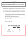
1
D
E S I G N E D
T O
L
E A D
Mega-Stor
TM
Stainless Steel, Indirect Water Heaters
• INSTALLATION AND OPERATING INSTRUCTIONS
• ENGINEERING MANUAL
• MAINTENANCE
• PARTS
CAUTION
1. having a toxicity rating or Class of 1, as listed in Clinical Toxicology of Commercial Products, 5th edition.
2. The pressure of the heat transfer medium must be limited to a
maximum of 30 PSIG by an approved safety or relief valve.
Manufacturer of Hydronic Heating Products
P.O. Box 14818 3633 I. Street
Philadelphia, PA 19134
www.crownboiler.com
CONTENTS
I.
Product Description . . . . . . . . . . . . . . . . . . . . . . . . . . . . . . . . . . . 2
III.
Sizing . . . . . . . . . . . . . . . . . . . . . . . . . . . . . . . . . . . . . . . . . . . . . . 4
IV.
Zone Design . . . . . . . . . . . . . . . . . . . . . . . . . . . . . . . . . . . . . . . . . 6
V.
Before Starting Installation . . . . . . . . . . . . . . . . . . . . . . . . . . . . . 11
VI.
Locating The Mega-Stor . . . . . . . . . . . . . . . . . . . . . . . . . . . . . . . 11
VII. Piping . . . . . . . . . . . . . . . . . . . . . . . . . . . . . . . . . . . . . . . . . . . . . . 12
Boiler Side Piping . . . . . . . . . . . . . . . . . . . . . . . . . . . . . . . 12
Domestic Piping . . . . . . . . . . . . . . . . . . . . . . . . . . . . . . . . 15
VIII. Wiring . . . . . . . . . . . . . . . . . . . . . . . . . . . . . . . . . . . . . . . . . . . . . 21
IX.
Start-up and Check-out . . . . . . . . . . . . . . . . . . . . . . . . . . . . . . . . 24
X.
Maintenance . . . . . . . . . . . . . . . . . . . . . . . . . . . . . . . . . . . . . . . . . 25
XI.
Parts . . . . . . . . . . . . . . . . . . . . . . . . . . . . . . . . . . . . . . . . . . . . . . . 26
1
I. PRODUCT DESCRIPTION
The Crown Mega-Stor series indirect water heater is designed to generate domestic hot water in conjunction with a hot water
boiler using forced boiler water circulation. This indirect water heater consists of a stainless steel tank in which a smooth stainless
steel coil is located. Boiler water is pumped through the coil and heats the water in the tank. This tank is not intended for use in
!
systems.
IMPORTANT NOTE
Some localities require indirect water heaters having a relief valve capacity in excess of 200,000 BTU/hr to be constructed and stamped in accordance with ASME requirements. Check with the local authority having jurisdiction before
installing an MS-79 or MS-119 with a boiler or boilers having a total gross output in excess of 200,000 BTU/hr.
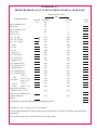
II. SPECIFICATIONS
TABLE 2.1: AHRI PERFORMANCE SPECIFICATIONS
Model
MS-26
MS-40
MS-53
MS-79
MS-119
MSH-40
MSH-53
First Hour
Rating
Continuous
Draw Rating
(Gal/hr)
(Gal/hr)
Standby
Loss
(°F/hr)
144
195
226
287
472
151
203
121
157
179
218
384
116
158
1.7
1.4
0.9
1.0
1.4
1.4
1.3
Minimum
Boiler
Output
(MBH)
77
102
114
145
225
75
101
Boiler Water Through Coil
Min Flow
(Gal/min)
8.0
8.0
8.0
8.0
12.7
8.0
8.0
Head Loss
(ft w.c.)
2.5
3.0
3.5
4.8
7.9
2.5
3.5
Notes:
AHRI ratings based on 77F DHW temperature rise (135F outlet temp) and 180F boiler supply temperature. The ratings in
"
#$
!%
be obtained under different conditions.
Pressure Ratings:
Maximum Allowable Tank Working Pressure - 150 psi
Design Hydrostatically Tested to 300 psi
2
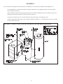
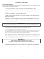
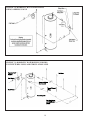
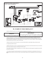
FIGURE 2.2: MEGA-STOR INDIRECT WATER HEATER
Vertical
Tank
9HUWLFDO7DQN
%
+27:$7(5287
0606
+27:$7(5287 $1'739$/9(
06²06
6+2:1:,7+237,21$/
02817,1*.,7)25
06+$1'06+
,168/$7('+$1'+2/(
-$&.(7&29(5
+$1'+2/(
81'(5&29(5
Horizontal
Tank
+RUL]RQWDO7DQN
739$/9(7$33,1* 0606
)520%2,/(56833/< $
+
*
(
&21752/
&21752/
'
$ )
72%2,/(55(7851 &
(
'
&2/':$7(5,1/(7 '5$,1&211(&7,21
&
)
)5217
5+6,'(
%
5($5
TABLE 2.3: PHYSICAL SPECIFICATIONS
Potable
Model Volume
(Gal.)
MS-26
25.6
MS-40
38.7
MS-53
51.1
MS-79
80.0
MS-119
111.7
MSH-40*
37.6
MSH-53*
51.0
Dimensions in Inches
A
38-3/4
54-3/4
47-7/8
69-1/4
66
24-3/8
24-3/8
B
C
D
20-1/4
2
9-3/4
20-1/4
2
9-3/4
23-7/8
2
9-7/8
23-3/4 1-5/8 10-1/4
29-1/2 2-1/2 12-3/4
23-7/8 34-11/16 3-5/8
23-7/8 44-7/8 3-5/8
E
22-1/2
25-3/4
26-3/4
29-1/4
36-1/4
5
5
F
------59-1/4
52-3/4
10-1/8
10-1/8
Coil
Surface
G
H
(Sq. Ft.)
----6.5
----8.6
----10.1
----15.1
----24.3
16-7/8 19-3/8
6.7
16-7/8 19-3/8
9.8
*Horizontal Tank
TABLE 2.4: CONNECTIONS
Key #
Description
1
2
3
4
5
Cold Water Inlet
To Boiler Return
From Boiler Supply
T&P Valve Tapping
Hot Water Out
Size (NPT)
MSH-40
MS-79
MSH-53
3/4M
1M
3/4M
3/4M
3/4M
3/4M
3/4F
1F
3/4M
1F
MS-26
MS-53
3/4M
3/4M
3/4M
--3/4M
3
MS-119
1-1/4M
1-1/4M
1-1/4M
1F
1-1/4F
Weight
Net Full
57 269
77 396
103 522
204 831
218 1178
127 449
168 595
III. SIZING
IMPORTANT
The following procedures are used to size indirect water heaters based on the amount of hot water which will be required
during a given hour. In doing so it is assumed that this demand will be evenly spread out over the course of the entire
hour.
THESE SIZING PROCEDURES ARE PROVIDED AS A GUIDE TO ASSIST THE PROFESSIONAL CONTRACTOR
IN SIZING MEGA-STOR TANKS. BECAUSE OF THE LARGE VARIETY OF DEMAND SITUATIONS
ENCOUNTERED IN THE FIELD, CROWN BOILER COMPANY CANNOT GUARANTEE THE SUITABILITY OF
THESE PROCEDURES TO ALL INSTALLATIONS.
Residential Applications
Table 3.1 shows the minimum sized Mega-Stor that should be considered for one and two family homes based on the numbers
!
'
#$
order to meet space heating demand, there is usually no need to add boiler capacity just for the Mega-Stor. Note that the sizing
recommendations shown in Table 3.1 may not provide satisfactory performance when there are unusually high peak demands,
+
;!
<<<=>
?@
';=
=
J+pool tubs, it is recommended that the Mega-Stor have a domestic water volume at least as large as the nominal volume of the tub.
Commercial Applications
Q
;
!+[ter of the ASHRAE Applications Handbook. Then use the data provided in Tables 2.1, 3.2, and 3.3 to select the boiler and MegaStor.
Table 3.1: Mega-Stor Sizing for Typical One and Two Family Units
(a)
(b)
(c)
(d)
(e)
Number
First Hour
Number of
Min. Boiler Output
of BedMega-Stor
Requirement
Bathrooms
(MBH)
rooms
(GPH)
1
MS-26
43
27
1 to 1 1/2
2
MS-40
60
36
3
MS-40
60
36
2
MS-40
60
36
3
MS-40
70
36
2 to 2 1/2
4
MS-40
72
38
5
MS-53
90
47
3
MS-53
72
47
4
MS-53
82
47
3 to 3 1/2
5
MS-53
90
47
6
MS-53
92
47
4
Table 3.2: Maximum Possible Continuous Draw
(180F Boiler Supply, 77F DHW Rise, 135F Outlet)
(a)
(b)
(c)
Continuous Draw Min Boiler Output
Mega-Stor
(Gal/min)
(MBH)
MS-26
2.0
77
MS-40
2.6
102
MS-53
3.0
114
MS-79
3.6
145
MS-119
6.4
225
MSH-40
1.9
75
MSH-53
2.6
101
Table 3.3: AHRI First Draw Rating*
(a)
(b)
(c)
Mega-Stor
Draw Rate
(GPM)
First Draw Rating
(Gal)
MS-26
MS-40
MS-53
MS-79
MS-119
MSH-40
MSH-53
2.0
2.6
3.0
3.6
6.4
1.9
2.6
22.6
38.2
46.5
69.3
88.3
35.6
44.6
* First Draw Rating is the amount of stored water available from a fully recovered Mega-Stor, with no boiler output during the
draw, before the outlet temperature falls by 25F. At draw rates higher than that shown in column (b), less stored hot water may be
available.
5
IV. ZONE DESIGN
IMPORTANT
section for information on sizing, piping and circulators for the Mega-Stor zone.
In designing the Mega-Stor zone piping system the following points should be considered:
1) Circulator or Zone Valve Zoning? - Circulator zones are usually a better choice. Zone valves have a relatively high
]?#
"$'!!
;
'
valve with a minimal delay in opening, such as a motorized type.
2) Priority Zoning - Priority zoning is used to divert all boiler output to the Mega-Stor when its zone calls for heat regardless of any simultaneous calls for heat from space heating zones. Priority zoning can be done using a 3-way zone
valve, or by using a relay to de-energize the heating zones when the Mega-Stor calls for heat. See the Piping and Wiring
Sections for more information on these zone systems.
3) Use Worksheet 1 to size piping and select a circulator for the Mega-Stor zone. To do this:
$Q
#$J
+
;
?
'
to all zones (zone manifolds, etc.).
$^"]?
$_
#$#$
!
]?
selected. Enter the result in column (d).
d) Total column (d). This is the total pressure drop for the Mega-Stor zone.
e) Use Table 4.1 or a circulator manufacturer’s literature to select a circulator which will develop the required
TABLE 4.1: SELECTING A CIRCULATOR
AVAILABLE HEAD (FT. W.C.)
Circulator
Taco 007
Taco 008
Taco 0014
Grundfos UPS 15-42F
Grundfos UP 26-64F
Flow
8.0 GPM
8.2
9.8
17.5
9.0
21.0
12.7 GPM
5.8
4.2
15.2
5.0
16.0
Select a circulator which has an Available Head greater than the pressure drop calculated using Worksheet 3.
6
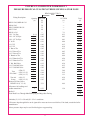
WORKSHEET 1:
PRESSURE DROP CALCULATIONS THROUGH MEGA-STOR ZONE
Fitting Description
MS-26, MSH-40 Coil
MS-40 Coil
MS-53, MSH-53 Coil
MS-79 Coil
MS-119 Coil
1 ft 1” St. Pipe
1 ft 1-1/4” St. Pipe
1 ft 1-1/2” St. Pipe
1” 90 El
1-1/4” El
1-1/2” El
1” Run of Tee
1-1/4” Run of Tee
1-1/2” Run of Tee
1” Branch of Tee
1-1/4” Branch of Tee
1-1/2” Branch of Tee
1” Std. Ball Valve
1-1/4” Std. Ball Valve
1-1/2” Std. Ball Valve
#220 (1”)
Taco
#221 (1-1/4”)
“Flo-Chek”
#222 (1-1/2”)
#431 (1”)
Taco Air
Scoop
#432 (1-1/4”)
Honeywell Zone Valves
V8043F1101 (1” Cv=8)
Allowance for bushings and
sudden transitions*
Quantity
(a)
ft
ft
ft
1
HEAD LOSS (FT W.C.)
Flow
8.0 GPM
12.7 GPM
(b)
(c)
2.5
--3.0
--3.5
--4.8
----7.9
0.05
0.13
0.01
0.03
0.01
0.01
0.16
0.40
0.06
0.15
0.04
0.10
0.05
0.13
0.02
0.05
0.01
0.03
0.26
0.66
0.08
0.20
0.05
0.13
0.12
0.30
0.06
0.15
0.02
0.05
2.18
5.49
0.84
2.12
0.44
1.11
0.15
0.38
0.05
0.25
2.31
4.69
0.53
1.34
Total
(d)
Boiler**
Total Head Loss Through Manifold Piping and Mega-Stor Zone
*Includes (2) 1-1/2 x 3/4 and (2) 1-1/2 x 1 transitions
**Pressure drop through boiler can be ignored for most cast iron or steel boilers. If in doubt, consult the boiler
manufacturer.
Above pressure drops may be used for black pipe or copper tubing.
7
EXAMPLE 1
'?'
}?~
?
"$Q
+=
";
?''
#
shown in bold) in column (a).
2) Since 8 GPM is required, use the pressure drops shown in column (b). Multiply each entry in column (a) by the corresponding pressure drop in column (b). Enter the result in column (d).
3) The total of column (d) is 7.94 ft. of head. This is the total pressure drop for the Mega-Stor zone.
4) Select a pump which will develop 7.94 ft of Head at 8 GPM. From Table 4.1, we see that either a Taco 007 or a Grund
fos UPS 15-42F can be used.
EXAMPLE 1: SIZING A CIRCULATOR AND PIPING FOR THE MEGA-STOR ZONE
8
FIGURE 4.2: COMPLETED WORKSHEET 3
PRESSURE DROP CALCULATIONS THROUGH MEGA-STOR ZONE
HEAD LOSS (FT W.C.)
Flow
Fitting Description
MS-26 Coil, MSH-40 Coil
MS-40 Coil
MS-53, MSH-53H Coil
MS-79 Coil
MS-119 Coil
1 ft 1” St. Pipe
1 ft 1-1/4” St. Pipe
1 ft 1-1/2” St. Pipe
1” 90 El
1-1/4” El
1-1/2” El
1” Run of Tee
1-1/4” Run of Tee
1-1/2” Run of Tee
1” Branch of Tee
1-1/4” Branch of Tee
1-1/2” Branch of Tee
1” Std. Ball Valve
1-1/4” Std. Ball Valve
1-1/2” Std. Ball Valve
#220 (1”)
Taco
#221 (1-1/4”)
“Flo-Chek”
#222 (1-1/2”)
#431 (1”)
Taco Air
Scoop
#432 (1-1/4”)
Honeywell Zone Valves
V8043F1101 (1” Cv=8)
Allowance for bushings and
sudden transitions*
Quantity
(a)
10 ft
6 ft
ft
6
3
1
2
1
1
1
8.0 GPM
(b)
2.5
3.0
3.5
4.8
--0.05
0.06
0.01
0.16
0.06
0.04
0.05
0.02
0.01
0.26
0.08
0.05
0.12
0.06
0.02
2.18
0.84
0.44
0.15
0.05
12.7 GPM
(c)
--------7.9
0.13
0.03
0.01
0.40
0.15
0.10
0.13
0.05
0.03
0.66
0.20
0.13
0.30
0.15
0.05
5.49
2.12
1.11
0.38
0.25
2.31
4.69
0.53
1.34
Boiler**
Total Head Loss Through Manifold Piping and Mega-Stor Zoning
Total
(d)
3.0
0.50
0.36
0.96
0.18
0.02
0.16
2.18
0.05
0.53
0
7.94
*Includes (2) 1-1/2 x 3/4 and (2) 1-1/2 x 1 transitions
**Pressure drop through boiler can be ignored for most cast iron or steel boilers. If in doubt, consult the boiler
manufacturer.
Above pressure drops may be used for black pipe or copper tubing.
9
V. BEFORE STARTING INSTALLATION
1) Be sure that the planned installation is in accordance with all local codes.
2) Be certain the domestic water supply to the tank has physical and chemical characteristics that fall within the limits shown
"+]
>;]
consulted.
3) Read and understand all installation requirements in this manual.
IMPORTANT
Water with characteristics outside the limits shown in
Table 5.1 may severely shorten the life of the tank due to
corrosion. Damage to tanks in such cases is not covered
under warranty.
TABLE 5.1: WATER CHEMISTRY
REQUIREMENTS
Water used in the Mega-Stor must have characteristics falling
within the following limits:
Characteristic
Min
Max
pH
Chloride (PPM)
6.0
0.0
8.0
80.0
VI. LOCATING THE MEGA-STOR
"$<
?
?=
?
capable of supporting it.
WARNING
Failure to properly support an MS tank could result in property damage or personal injury.
2) Locate the Mega-Stor in a location where a leak in the tank, the adjacent piping, or an open T&P valve will not damage the
surrounding structure. If the area around the desired tank location is highly susceptible to water damage, install the MegaStor in a pan with a drain.
<$?
!'
!
called for in Table 2.1 through the coil. Also, the further the Mega-Stor is from the boiler, the longer the response of the
boiler will be to a call from the Mega-Stor zone. If long runs exist between the boiler and Mega-Stor it is advisable to
insulate the piping.
10
VII. PIPING
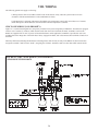
1) BOILER SIDE PIPING
Figures 7.1 thru 7.4 show typical boiler side piping for several common situations. Regardless of which system is used it is impera!
"!
]
'
'
pump. To determine the pipe/pump sizes required see page 6.
The systems shown in Figures 7.1 thru 7.4 are described below:
STANDARD CIRCULATOR ZONE
This system is just like the circ zone system on a straight heat job except that one of the zones goes to the MS tank instead of radiation. As on any circulator zone system, check valves should be installed in each zone to prevent unwanted circulation through zones
which are not calling for heat. Figure 7.1 illustrates typical circ zone piping.
ZONE VALVE SYSTEM
Figure 7.2 illustrates a typical Mega-Stor installation using zone valves. The circulator must be large enough to move boiler water
";
]'
3-WAY ZONE VALVE SYSTEM
Figure 7.3 illustrates typical piping using a 3-way zone valve. In this system a 3-way zone valve is used which has a common
port, a “normally open” port, and a “normally closed” port. The zone valve motor is wired so as to be energized by the Mega-Stor
thermostat (see Part VIII for wiring information). The common side of the zone valve is connected to the boiler. The heating zone is
connected to the normally open side of the zone valve and the Mega-Stor coil is connected to the normally closed side of the zone
!!}
?
;
';
open side of the 3-way valve, to the boiler. As soon as the Mega-Stor calls for heat, the zone valve is energized, and boiler water
?'
MEGA-STOR MANIFOLD PIPING (BOILER SIDE)
Multiple tank installations must be done in the “reverse return” manner illustrated in Figure 7.4. The reason for this is to create the
#
$=
'
"J;?
;
zone piping common to both tanks must be capable of moving 16 GPM (2 x 8GPM).
?
!
'
';
!
through each coil when two Mega-Stors of different sizes are placed in the same manifold. For this reason it is best not to mix
Mega-Stors of two different sizes in the same zone if their recovery is critical.
11
FIGURE 7.1: BOILER-SIDE PIPING USING CIRCULATOR ZONES
FIGURE 7.2: BOILER-SIDE PIPING USING ZONE VALVES (2-WAY)
12
FIGURE 7.3: BOILER-SIDE PIPING USING A THREE WAY ZONE VALVE
FIGURE 7.4: BOILER-SIDE PIPING FOR MULTIPLE MEGA-STORS
13
2) DOMESTIC SIDE PIPING
BASIC DOMESTIC PIPING
Figure 7.6A shows typical domestic water piping for a Mega-Stor. All components except the control are provided by the installer.
The function of the components shown are as follows:
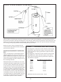
a) Temperature Control (required) - This control is provided by Crown and must be installed in the aquastat
well location of the water heater indicated in Figure 2.2. Remove the cover and loosen the clamping screws. Insert the
capillary bulb so that it is “bottomed out” in the control well as shown in Figure 7.5 and screw the control clamp
securely in the well groove at the end of the well. See Section VIII for wiring details and Section IX for instructions on
adjusting the temperature setting.
b) Shut-off valves (recommended) - Use to isolate the tank for servicing.
$=!#]
$Q
!=?!
that inlet water pressure drops.
$
=#]=!
$
=
!
=!
;
=
]
volume will otherwise have no place to go and the T&P valve will open. Use an expansion tank designed for use on
domestic water systems such as Watts DET series expansion tank. Refer to the expansion tank manufacturer’s literature
for the proper size expansion tank to use.
IMPORTANT
If an expansion tank is used, do not put any valves between the expansion tank and Mega-Stor inlet.
e) Unions (optional) - Use to disconnect the Mega-Stor in the event that this is necessary.
f) Drain (Required) - Used to drain the tank for inspection or servicing.
g) Temperature/Pressure Relief Valve (required) - Opens to relieve excess pressure or temperature which has developed
in the Mega-Stor. This valve must comply with ANSI Z21.22 Standard for Relief Valves and Automatic gas Shutoff
Devices for Hot Water Supply Systems and must be sized in accordance with Table 7.7.
Pipe this valve as shown in Figure 7.6B or 7.6C. Run the discharge to a location where hot water discharge will not cause
injury or damage. Leave a 6” gap between the T&P valve pipe termination and the drain or closest obstruction. Do not
run T&P valve discharge pipe to the outdoors or other potentially freezing location. Make sure the discharge line is
installed to allow complete drainage of both the valve and line.
IMPORTANT
Do not put any valves between the relief valve and the tank.
Do not install a reducing coupling or otherwise restrict the discharge line.
h) Vacuum Breaker (Recommended) - This valve protects the tank in the event that the pressure in the tank falls below
atmospheric. Use a Watts N-36 or equivalent.
i) Heat Trap (Optional) - The heat trap retards the migration of heat from the Mega-Stor up the hot water supply pipe.
14
FIGURE 7.5: AQUASTAT INSTALLATION
MEGA-STOR PIPING WITH A “TEMPERATURE LIMITING VALVE”
Usually, the maximum temperature of the outlet water will stay near the setting of the Mega-Stor control. In some cases, however,
!
!!
This device blends a controlled amount of cold water with the hot water leaving the Mega-Stor so that water at a more constant
temperature exits the mixing valve. Typical thermostatic mixing valve piping is illustrated in Figure 7.8. Consult a licensed
plumber or the local plumbing authority for requirements in your area.
WARNING
A thermostatic mixing valve does not eliminate the risk of scalding.
* Set the Mega-Stor thermostat as low as practical.
* Feel water before bathing or showering
];
!
designed for such service. Install these devices in accordance with their
manufacturer’s instructions.
DOMESTIC WATER PIPING FOR DISTANT FIXTURES
]
?
J
}
!
!
?;
J
;
=
the Mega-Stor. A small bronze circulator is mounted in this line and is wired so as to run continuously. A check valve in this line
?
15
FIGURE 7.6A: BASIC DOMESTIC WATER PIPING
+
;'!
?>
;=?!+
;
!
=!!!
?
=
Because hot water is always circulated in the hot
water branch the entire branch should be insulated to
prevent excessive heat loss.
MANIFOLD DOMESTIC WATER PIPING
Figure 7.10 illustrates the recommended method of
piping the domestic water side of several tanks together. All Mega-Stors are piped in a “reverse- return”
manner just like the boiler piping. This balances the
pressure drop through each tank, resulting in an even
=
Each tank must have its own T&P valve. It is recommended that each tank be equipped with its own isolation valves, unions, and drains so that one tank may
be removed from the system. If local codes require a
=!;==!
be used for tanks or each tank must be equipped with
=!=
!
=!;=
!
==!
is permitted, an expansion tank must be sized to accommodate the expansion volume of all tanks.
TABLE 7.7: MINIMUM T&P VALVE SIZES
*If the Mega-Stor is connected to a boiler which has a Gross Output
LESS than the “Max. T&P Valve Capacity” shown below, install
a T&P valve having a capacity greater than or equal to the boiler’s
Gross Output.
*If the Mega-Stor is connected to a boiler which has a Gross Output
GREATER than the “Max. T&P Valve Capacity” shown below,
install a T&P valve having a capacity greater than or equal to the
“Max T&P Valve Capacity.”
Model
Max T&P Valve Capacity (BTU/hr)
MS-26
MS-40
MS-53
MS-79
MS-119
MSH-40
MSH-53
172,800
181,800
199,800
215,100
445,635
103,344
145,289
*Maximum T&P valve pressure setting - 150 psi
16
FIGURE 7.6B: CORRECT TEMPERATURE & PRESSURE
VALVE PIPING FOR MS-26, MS-40, MS-53
FIGURE 7.6C: CORRECT TEMPERATURE & PRESSURE VALVE PIPING FOR MS-79, MS-119
17
FIGURE 7.8: DOMESTIC HOT WATER PIPING
USING A MIXING VALVE
FIGURE 7.9: DOMESTIC WATER PIPING FOR DISTANT FIXTURES USING A RECIRCULATION LINE
18
FIGURE 7.10: DOMESTIC HOT WATER PIPING
USING MULTIPLE MEGA-STORS
19
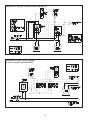
VIII. WIRING
The following general notes apply to all wiring:
1) Wiring must be done in accordance with all codes. In the absence of any codes the system must be wired in
accordance with the National Electric Code (ANSI/ZFPA 70-1990).
2) The Mega-Stor is equipped with Honeywell L4006A series temperature control. This control has a set of contacts
=
=
CIRC ZONE WIRING (NON PRIORITY)
Figure 8.1 is a connections diagram for a non-priority circulator zone system using Honeywell R845A’s. The R845A is equipped
with two sets of contacts (3,4 and 5,6) which become made when the T and T terminals are made. Terminals 1 and 2 on the
R845A are supplied with 110 VAC to power its internal transformer. In this application one R845A is provided for each zone
including that of the Mega-Stor. If the boiler has a factory equipped circulator, this is disconnected from terminals Cl and C2 on
the boiler.
When any thermostat (including the thermostat on the Mega-Stor) calls for heat, the relay in the R845A for that zone becomes
energized. Terminals 3 and 4 become “made”, energizing the circulator. Terminals 5 and 6 are also made which start the boiler.
FIGURE 8.1: CIRC. ZONE WIRING (NON-PRIORITY)
USING HONEYWELL R845’S
20
CIRCULATOR ZONE WIRING (PRIORITY)
Figure 8.2 is a connections diagram for priority circulator zoning. This system is similar to non-priority circulator zoning except
that a Honeywell R8285B relay is used in place of the R845A on the Mega-Stor zone. This relay is equipped with its own 24 volt
transformer and D.P.D.T. contacts. The Mega-Stor control is connected to terminals R and G so that when the Mega-Stor control
calls for heat the relay is energized.
One set of contacts on the R8285B is used to switch line voltage. On this set of contacts the common is connected to an unswitched “hot”. The normally closed contact is connected to terminal #1 on each of the space heating zone’s R845A’s. The normally open contact is connected to the Mega-Stor zone circulator.
The normally closed contact on the other set of R8285B contacts is not used. The common and normally open contacts are connected in parallel with terminals #5 and #6 on the space heating zone R845As.
As long as the Mega-Stor zone does not call for heat, the R845As for the heating zones have 110 VAC across their 1 and 2 terminals and the heating zones will function as described in the non-priority circulator zone section. As soon as the Mega-Stor calls for
heat, however, the normally closed terminals in the R8285B open, de-energizing the heating zones and energizing the Mega-Stor
circulator.
The other set of contacts in the R8285B (connected across the boiler thermostat connections) become “made” which brings on the
boiler.
ZONE VALVES (NON PRIORITY)
Figure 8.3 is a connections diagram for a zone system using Honeywell V8043F motorized zone valves. The motor on these
valves is connected between TH and TR. TH/TR is provided for the electrician’s convenience as a binding post and is connected
to nothing inside the valve. The “endswitch” terminals are connected to a set of switch contacts inside the valve which become
made when the
valve is open.
A call for heat from any thermostat or the Mega-Stor aquastat results in the application of 24 volts across the motor in that zone’s
zone valve. This drives open the zone valve. When the valve has opened, the endswitch in that zone valve makes and brings on
the boiler.
ZONE VALVES (2-WAY PRIORITY)
Figure 8.4 is a connections diagram for a priority zone system using Honeywell V8043F motorized valves. An R8285B relay is
used which is equipped with its own transformer and a set of S.P.D.T. contacts.
The Mega-Stor control is connected to terminals R and G on the R8285B so that when the Mega-Stor control calls for heat, the
relay coil is energized. One side of the transformer is connected to the common contact. The normally closed contact is connected
to all space heating thermostats. The normally open contact is connected directly to the Mega-Stor zone valve motor.
As long as the Mega-Stor is not calling for heat, power is supplied to all space heating thermostats and a call from any space
heating thermostat will energize that zone’s zone valve and bring on the boiler. As soon as the Mega-stor calls for heat, however,
the normally closed contacts, which supply all power to the space heating thermostats, open. This de-energizes the heating zones
and closes any open space heating zone valves. At the same time, the normally open contacts in the R8285B become made which
energizes the Mega-Stor zone valve. The Mega-Stor zone valve opens and its endswitch brings on the boiler.
If four or fewer zones (including the Mega-Stor zone) are present, the transformer in the R8285B may be used instead of an external transformer. Use terminals R and C with C being the “common” side of the 24 volt wiring.
21
FIGURE 8.2: CIRCULATOR ZONING (PRIORITY)
FIGURE 8.3: ZONE VALVE WIRING
(2-WAY VALVES, NON-PRIORITY)
22
FIGURE 8.4: ZONE VALVE WIRING
(2-WAY VALVES, PRIORITY)
IX. START-UP AND CHECK-OUT
1) Make sure that the system is free of leaks and that air is purged from the system.
WARNING
!
IMPORTANT
Fix any leaks found before proceeding further. Leakage from
the boiler piping can result in severe damage to the boiler.
$?
_
!
}
;
?!
ticularly important if the Mega-Stor will be unused for an extended period of time after installation. Flush the Mega-Stor
by drawing at least three times its volume from the tank.
3) Make sure that all electrical connections are correctly made and that no exposed high voltage wiring is present.
4) Temporarily disable the burner.
5) Make sure that each zone valve or circulator operates when, and only when, its thermostat calls for heat. Let each zone
operate long enough to purge any remaining air from the system.
6) Re-enable the burner and allow the Mega-Stor zone to operate. Make sure that the Mega-Stor aquastat shuts down the
'
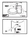
7) The setting of Mega-Stor aquastat temperature control determines the maximum water temperature in the tank. The
J"J
;
~J
23
J
;>
]
tic water needs. Because hot water presents a scald hazard, it is best to set the thermostat at 120ºF or lower and raise it
only if necessary to provide adequate hot water. See Table 9.2 for more information about scalding.
$Q
!>
J"
setting on the dial is aligned with the notch in the temperature indication window.
b) After the water heater completes a heat-up cycle, check the water temperature at the faucet. Allow enough
=}>
temperature setting as necessary.
i) Adjusting to a lower temperature setting will not immediately affect the water temperature. Draw
^
$$
ii) Adjusting to a higher temperature setting may not immediately affect the water temperature if
;
$$
;
water or allow the water heater to sit until a heat-up cycle is initiated. Repeat steps a) and b).
APPROXIMATE TIME/TEMPERATURE
RELATIONSHIPS FOR SCALDING
60
40
"J
"J
"<J
"<J
"~J
"~J
"J
"J
More than 5 minutes
1-1/2 to 2 minutes
About 30 seconds
About 10 seconds
Less than 5 seconds
Less than 3 seconds
About 1-1/2 seconds
About 1 second
TABLE 9.2: SCALD RISK
FIGURE 9.1: TEMPERATURE CONTROL
X. MAINTENANCE
The Mega-Stor is an extremely simple device and as such requires very little maintenance. There are, however, several items
which should be checked out on an annual or as needed basis to ensure a reliable supply of hot water:
* On an annual basis, remove the black cover over the handhole and make sure that the handhole cover is leak-tight.
* Make sure that the rest of the boiler and domestic water piping is free of leaks.
* If there is an oil lubricated circulator in the system, make sure that it is lubricated as called for by the circulator
manufacturer.
* The Mega-Stor depends upon the boiler for a source of heat and is therefore only as reliable as the boiler. Make sure
that the boiler is maintained in accordance with the boiler manufacturer’s instructions.
* If a water treatment system is required to keep the water chemistry within the parameters shown in Table 5.1, make
sure that this system is properly maintained.
24
XI. PARTS
Key #
1
5
6
7
8
10
Part #
35-3200
20-021
20-022
20-023
90-025
20-024*
Description
Thermostat (L4006A2114)
Handhole Cover
“O” Ring Gasket
Handhold Cover Bracket
M10 Nut
Handhold Jacket Cover
Notes:
All part numbers are per item.
*This part not used on MS-79 or MS-119
25
Qty./Tank
1
1
1
1
1
1
26
Manufacturer of Hydronic Heating Products
P.O. Box 14818 3633 I. Street
Philadelphia, PA 19134
www.crownboiler.com
27
PN 98-060 • 05/13 Rev 8