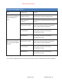
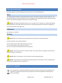
1
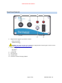
OM2443
PSU1 Power Supply Unit
Distributed By:
GMW Associates
955 Industrial Road, San Carlos, CA, 94070 USA
PHONE: +1 650-802-8292 FAX: +1 650-802-8298
EMAIL: [email protected]
WEB: www.gmw.com
BARTINGTON INSTRUMENT
Table of Contents
How to use this Manual ....................................................................... 3
Symbols Glossary .......................................................................... 3
Important Safety Information .............................................................. 3
Applicability .......................................................................................... 4
Compatible Magnetometers ................................................................ 4
Introduction to the PSU1...................................................................... 5
Summary ....................................................................................... 5
Functional Description .................................................................. 5
Power .................................................................................... 5
Signal Buffering ..................................................................... 5
Filtering ................................................................................. 5
PSU1 Inputs, Outputs and Controls ...................................................... 6
Back Panel Connections and Controls .......................................... 6
Front Panel Controls ..................................................................... 7
Installing the PSU1 ............................................................................... 8
Installing and Replacing the Internal Batteries............................. 8
Initial charging of the battery cells ............................................. 11
Location of the Equipment ......................................................... 11
Potentially hazardous locations .......................................... 11
Orientation.......................................................................... 11
Temperature ....................................................................... 11
Proximity to other equipment ............................................ 11
Connecting the Equipment ......................................................... 12
Page 1 of 16
OM2443 ISSUE 1.0
BARTINGTON INSTRUMENT
Initial Settings ............................................................................. 12
Magnetometer output type selection ................................ 12
Using the PSU1 ................................................................................... 13
Environmental Precautions ........................................................ 13
Switching On and Off .................................................................. 13
Troubleshooting ................................................................................. 14
Troubleshooting (contd.).................................................................... 15
Care and Maintenance ....................................................................... 16
Fuses ........................................................................................... 16
Calibration .................................................................................. 16
Cleaning ...................................................................................... 16
End of Life Disposal ............................................................................ 16
Page 2 of 16
OM2443 ISSUE 1.0
BARTINGTON INSTRUMENT
How to use this Manual
This document describes the installation, operation and maintenance of the PSU1 Power Supply Unit.
Take the time to get well acquainted with your PSU1 by reading this manual. Knowing and understanding
the equipment will ensure you experience the most reliable operation.
When service or maintenance is required, please contact Bartington Instruments or your local agent
company.
Technical specifications for this product can be found in the appropriate datasheets. Details can be found
on the Bartington Instruments website.
Visit the Bartington Instruments website regularly for more information about any changes to our product
range, for software downloads, datasheets and for support details. You can access all the information you
need about your equipment, including service information at http://www.bartington.com/.
Symbols Glossary
The following symbols used within this manual call your attention to specific types of information:
WARNING: Indicates a situation in which serious bodily injury or death could result if the warning is
ignored.
Caution: Indicates a situation in which bodily injury or damage to your instrument, or both, could
result if the caution is ignored.
This symbol identifies items that must be disposed of safely to prevent unnecessary damage to the
environment.
Note: A note provides useful supporting information and sometimes suggests how to make better use of
your purchase.
Important Safety Information
WARNING: The PSU1 is fitted with AA size NiMH (Nickel Metal Hydride) rechargeable batteries.
Only AA size rechargeable batteries, which are specified as compatible in the relevant datasheet can be
used in this product.
WARNING: The fitting of non-approved battery cells may be dangerous and could affect the safety of
users, damage the equipment and also invalidate the terms and conditions of the Warranty.
Page 3 of 16
OM2443 ISSUE 1.0
BARTINGTON INSTRUMENT
Applicability
Caution: This manual applies only to the PSU1 Power Supply Unit. For the earlier Mag-03PSU, please
use the manual supplied with that unit or visit the Bartington Instruments website to obtain a copy. If you
require assistance locating the correct manual for your equipment, please contact the Bartington
Instruments helpdesk.
Compatible Magnetometers
Caution: Use of incompatible magnetometers may cause damage to the PSU1 and/or the
magnetometer. The PSU1 is designed to operate with various magnetometers. For the current list refer to
the datasheet.
Page 4 of 16
OM2443 ISSUE 1.0
BARTINGTON INSTRUMENT
Introduction to the PSU1
Summary
The PSU1 provides a battery backed power supply of ±12 V for the Mag-03 series of three axis fluxgate
magnetic sensors. It also contains filters for the analog outputs of the sensor.
Functional Description
Power
The PSU1 will supply ±12V d.c. for powering a range of magnetometers. Please refer to the datasheet for
the latest list of compatible products. The power is supplied from the internal, rechargeable batteries or
from the plug-in power adapter, which is also used to charge the PSU1 batteries.
Note: The PSU1 will operate without any battery cells being installed. To install, or replace defective cells
refer to the section on Installing and Replacing the Internal Batteries.
Signal Buffering
Buffered, single-ended output signals on BNC connectors from differential or single-ended output
magnetometers.
After filtering, each analog signal is fed to the appropriate BNC connector via a low impedance buffer.
These buffers allow long cables and low input impedance data acquisition systems to be used. Refer to the
appropriate datasheet for maximum loads.
The output common return is also buffered to eliminate crosstalk due to signal currents sharing the Va
common return. A high impedance ac path is also provided between the Va common and cable screen to
improve ac noise performance.
Filtering
Filtering is provided by a low-pass filter and selectable high-pass filter for d.c. or a.c. coupling.
A low pass and a high pass filter are included in each of the channels for the signals from the X, Y and Z
axes of the sensor. Refer to the appropriate datasheet for the frequency response of the filters.
The low pass filters remove the high frequency noise components of the signal from the sensor.
The high pass filters are intended to isolate the DC or static field component so that the alternating
components above this frequency can be measured or analysed.
Page 5 of 16
OM2443 ISSUE 1.0
BARTINGTON INSTRUMENT
PSU1 Inputs, Outputs and Controls
Back Panel Connections and Controls
1
2
3
5
1.
2.
3.
4.
5.
4
X Signal Conditioned Output
Y Signal Conditioned Output
Z Signal Conditioned Output
The three BNC connectors carry the conditioned analogue output voltages. The conditioned
outputs are the magnetometer X, Y and Z signals after they have been modified by the low/high
pass filters and, if a balanced output magnetometer is connected, converted to single-sided
signals.
Space for unique serial number
Magnetometer Socket
This multi-pin socket is for the connection of the magnetometer cable.
Note: Ensure correct orientation of the connector (indicated by the cut-out on the connector body
aligning with the notch in the socket
Page 6 of 16
OM2443 ISSUE 1.0
BARTINGTON INSTRUMENT
Front Panel Controls
6
6.
7
8
9
11
10
Magnetometer Output Type Selector Switch
Balanced (out)
Unbalanced (in)
Caution: This switch must be set to match your magnetometer output type to ensure correct
results (see Magnetometer output type selection)
7. DC/AC Coupling (High Pass Filter (HPF) Control)
DC (out)
8.
9.
10.
11.
AC (in)
Charge LED
ON / OFF LED
On/Off Switch
Socket for external charging adapter
Page 7 of 16
OM2443 ISSUE 1.0
BARTINGTON INSTRUMENT
Installing the PSU1
Installing and Replacing the Internal Batteries
The battery cells for the PSU1 are not installed before shipping. To install the batteries cells for first use (or
to replace defective cells) use the following procedure:
C
B
A
Key:
A – Enclosure lid retaining screw
B – Enclosure lid retaining screw
C – Earth lead fixing (do not remove)
1. Place the PSU1 on a suitable surface with the underside facing up and the two enclosure lid
retaining screws nearest to you.
2. Using a flat-bladed screwdriver of the appropriate size, fully loosen screw A to allow the edge of
the lid to clear the enclosure end cap.
Page 8 of 16
OM2443 ISSUE 1.0
BARTINGTON INSTRUMENT
3. Fully loosen screw B and the lid of the enclosure will lift due to the internal springs.
4. Lift the lid and place aside to gain access to the battery cell compartment.
5. Insert each cell into the compartment in turn. Always fit the negative end of the cell first. Press the
cell back against spring pressure until the positive terminal can be located in the holder.
Page 9 of 16
OM2443 ISSUE 1.0
BARTINGTON INSTRUMENT
6. When all 5 cells are in place, locate the back edge of the lid in the enclosure
7. Tighten screws A and B in any order
8. To remove discharged or defective cells follow the above procedure
Page 10 of 16
OM2443 ISSUE 1.0
BARTINGTON INSTRUMENT
Initial charging of the battery cells
To charge the PSU1 battery, connect the mains charger and switch on the mains supply (if appropriate).
The charging LED (item 8) will begin to flash indicating that “fast charging” is taking place. Once the fast
charge cycle has completed the LED will stop flashing and be lit (ON) continuously to indicate “trickle
charging” is ongoing.
Note: When battery cells are inserted for the first time, they should be continuously charged for 16 hours
to ensure full capacity.
Note: The PSU1 can be used whilst charging the battery cells or directly from mains power without any
battery cells being installed. However the outputs may carry some charger noise.
Note: If the PSU1 is powered by the mains charger with no batteries cells installed, the charging LED may
flash. This is normal and can be ignored.
Note: To prepare for long periods away from a charging source battery cells may be pre-charged and used
to replace discharged cells in the field.
Location of the Equipment
Potentially hazardous locations
WARNING: The charger supplied with this equipment is powered by mains electricity. It should not be
used in wet or damp locations, where water may enter the unit and create a safety hazard.
Orientation
The PSU1 can be orientated horizontally or vertically.
Temperature
To minimise temperature induced drift effects, position the PSU1:
In a constant ambient temperature
Out of direct sunlight
Proximity to other equipment
The PSU1 contains no high frequency electronics likely to cause emissions which could cause interference
with other equipment. The unit is unlikely to be affected by interference from other equipment in the
normal operating environment.
Note: The PSU1 is inherently magnetic and should, therefore, be sited as far from any magnetometers as
possible.
Page 11 of 16
OM2443 ISSUE 1.0
BARTINGTON INSTRUMENT
Connecting the Equipment
Caution: Connection between the magnetometer and the power supply should not be made or
broken with the power supply switched on as this could cause damage to the magnetometer.
Connect the equipment in the following sequence:
1. Ensure the ON/OFF switch, item 10, is OFF (position “0”).
2. Connect the magnetometer to the PSU1 magnetometer socket. Ensure the connector pins are
correctly aligned with those in the socket. The locking ring should be hand-tightened only.
3. Connect BNC outputs to your external equipment, as required.
Initial Settings
Magnetometer output type selection
Before switching on the equipment, set the magnetometer output type selector switch to the correct
position for your magnetometer. Refer to the appropriate magnetometer datasheets.
Page 12 of 16
OM2443 ISSUE 1.0
BARTINGTON INSTRUMENT
Using the PSU1
Environmental Precautions
Refer to the Mag-03 datasheet for maximum environmental, electrical and mechanical ratings for the
PSU1.
Caution: Exceeding the maximum environmental ratings may cause irreparable damage to the
equipment.
Switching On and Off
Caution: Connect the magnetometer before switching on the PSU1, as connecting a “live” cable to
the magnetometer may cause damage. Similarly, switch off the PSU1 before disconnecting the
magnetometer.
With the Power switch (item 10) ON (position “1”), the power LED (item 9) will be continuously lit (ON).
Note: For best results, after switching on the power, leave the PSU1 for 20 minutes for the internal
temperature to stabilise, before performing any measurements.
Page 13 of 16
OM2443 ISSUE 1.0
BARTINGTON INSTRUMENT
Troubleshooting
If the PSU1 exhibits unexpected behaviour, please check possible causes in the following table:
Fault
Possible Cause
Solution
No power output from
the PSU1
Battery flat
Recharge
Battery expired
Replace batteries and charge
Battery not fitted
Fit batteries and charge
None of the above
Return to Bartington Instruments for repair
Failed 12V charger
Replace charger
Battery not fitted
Fit batteries and charge
None of the above
Return to Bartington Instruments for repair
PSU1 does not hold its
charge (reduced battery
operation)
Batteries expired
Replace batteries and charge
PSU1 stuck in AC or DC
coupling mode
Defective component
Return to Bartington Instruments for repair
PSU1 stuck in Balanced or
Unbalanced mode
Defective component
Return to Bartington Instruments for repair
One or both LEDs do not
light correctly
Defective component
Return to Bartington Instruments for repair
PSU1 does not charge
Page 14 of 16
OM2443 ISSUE 1.0
BARTINGTON INSTRUMENT
Troubleshooting (contd.)
Fault
Possible Cause
Solution
With a sensor connected
all output signals are
faulty
Coupled incorrectly
Check position of AC/DC coupling switch
Balance mode set
incorrectly
Check position of balanced/unbalanced mode
switch
Defective sensor cable
Check sensor cable using relevant datasheet.
Return to BI if found to be defective
Sensor defective
Return PSU1 and sensor to Bartington
Instruments for repair
PSU1 defective
Return PSU1 and sensor to Bartington
Instruments for repair
Defective sensor cable
Check sensor cable using relevant datasheet.
Return to BI if found to be defective
Sensor defective
Return PSU1 and sensor to Bartington
Instruments for repair
PSU1 defective
Return PSU1 and sensor to Bartington
Instruments for repair
With a sensor connected
one, or two output signals
are faulty
If the solutions suggested above do not fix the fault, please contact the Bartington Instruments helpdesk.
Page 15 of 16
OM2443 ISSUE 1.0
BARTINGTON INSTRUMENT
Care and Maintenance
The PSU1 requires no routine maintenance. There are no user serviceable parts.
Fuses
As a safety feature the PSU1 is fitted with a thermal fuse. If the PSU1 overheats, which could occur as a
result of the fitment of incorrect battery cells, the charging circuit will be permanently isolated. The PSU1
must be returned to Bartington Instruments for checks and repair.
Caution: No attempt should be made by a user to repair the unit. Repairs by unauthorised people
may be dangerous and could affect the safety of users, damage the equipment and also invalidate the
terms and conditions of the Warranty.
Calibration
No calibration is required.
Cleaning
Caution: Disconnect the electrical supply before performing any cleaning operation.
Periodic cleaning is not normally required.
If the system becomes soiled and cleaning is necessary:
1/ Use a damp cloth to clean the outer surfaces.
2/ Use an air duster to blow debris from the connectors.
Caution: Ensure water does not enter the system. The system must be completely dry before the
electrical supply is reconnected.
Caution: Never use chemicals, such as solvents, when cleaning the PSU1.
Caution: Take particular care when cleaning around electrical connections. Bent or damaged pins
may cause the magnetometer to malfunction.
End of Life Disposal
This symbol of the crossed-out wheelie bin indicates that the product (electrical and electronic
equipment) should not be placed in municipal waste. Check local regulations for disposal of
electronic products.
Page 16 of 16
OM2443 ISSUE 1.0