1
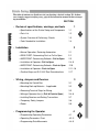
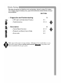
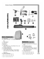
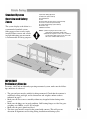
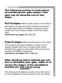
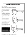
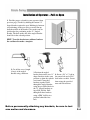
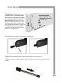
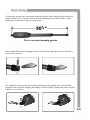
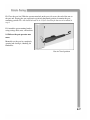
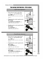
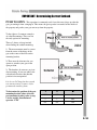
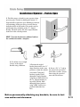
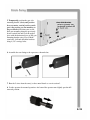
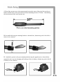
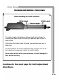
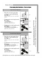
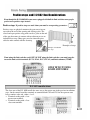
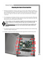
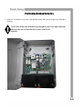
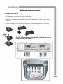
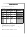
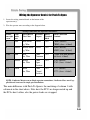
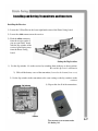
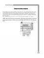
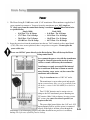
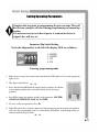
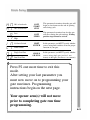
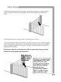
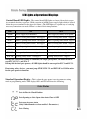
Instruction Manual for the
E-S 1600 / E-S 1602 Series
Manufactured by
CE DECLARATION OF CONFORMITY OF MACHINES
(Directive 89/392/EEC, Annex II, Part B)
Manufacturer: FAAC S.p.A.
Address: Via Benini, 1 – 40069 Zola Predosa Bologna – Italy
Declares that: 409 A.K.A. Estate Swing (USA) mod operator
•
Is built to be integrated into a machine or to be assembled with other machinery to create a machine under the provisions
of Directive 89/392/EEC, and subsequent amendments 91/368/EEC, 93/44/EEC.
•
Conforms to the essential safety requirements of the following EEC directives:
o
73/23/EEC and subsequent amendment 93/68/EEC, 89/336/EEC and subsequent amendment 92/31/EEC and
93/68/EEC.
o
And also declares the it is prohibited to put into service the machinery until the machine in which it will be
integrated or of which it will become a component has been identified and declared as conforming to the
conditions of Directive 89/392/EEC and subsequent amendments assimilated under national laws under DPR
#459 of July 24, 1996.
Bologna, January 1, 2002
Managing Director
A. Bassi
1.
2.
3.
4.
5.
6.
7.
8.
9.
Abassi
Warnings for the installer
General safety obligations
Attention! To ensure the safety of people, it is important that you read all the following instructions. Incorrect installation or incorrect
use of the product could cause serious harm to people.
Carefully read the instructions before beginning to install the product.
Store these instructions for future reference.
This product was designed and built strictly for the use indicated in the documentation. Any other use, not expressly indicated here,
could compromise the good condition/operation of the product and/or be a source of danger.
FAAC declines all liability caused by improper use or use other than that for which automated system was intended.
Do not install the equipment in an explosive atmosphere; the presence of inflammable gas or fumes is a serious danger to safety.
The mechanical parts must conform to the provisions of Standards EN 12604 and EN 12605.
For non-EU countries, to obtain an adequate level of safety, the standards mentioned above must be observed, in addition to national
legal regulations.
FAAC is not responsible for failure to observe Good Technique in the construction of the closing elements to be motorized, of for any
deformation that may occur during use.
The installation must conform to Standards EN 12453 and EN 12445.
The safety level of the automated system must be C+D.
10. Before attempting any job on the system, cut out electrical power and disconnect the batteries.
11. The main power supply of the automated system must be fitted with an all-pole switch with contact opening distance of 3 mm or
greater. Use of a 6A thermal breaker will all-pole circuit break is recommended.
12. Make sure that a differential switch with threshold of 0.03 A is fitted upstream of the system.
13. Make sure that the earthing system is perfectly constructed, and connect metal parts of the means of the closure to it.
14. The automated system is supplied with an intrinsic anti-crushing safety device consisting of a torque control. Nevertheless, its tripping
threshold must be checked as specified in the Standards indicated at point 10.
15. The safety devices (EN 12978 standard) protect any danger areas against mechanical movement risks, such as crushing, dragging, and
shearing.
16. Use of at least one indicator-light (e.g. FAACLIGHT 12VDC) is recommended for every system, as well as a warning sign adequately
secured to the frame structure, in addition to the devices mentioned at point “15”.
17. FAAC declines all liability as concerns safety and efficient operation of the automated system, is system components not produced by
FAAC are used.
18. For maintenance, strictly use original parts by FAAC.
19. Do not in any way modify the components of the automated system.
20. The installer shall supply all information concerning manual operation of the system in case of an emergency, and shall hand over to
the user the warnings handbook supplied with the product.
21. Do not allow children or adults to stay near the product while it is operating.
22. Keep remote controls or other pulse generators away from children, to prevent the automated system from being activated involuntarily.
23. Transit through the leaves is allowed only when the gate is fully open.
24. The user must not attempt any kind of repair or direct action whatever and contact qualified personnel only.
25. Do not short-circuit the poles of the batteries and do not try to recharge the batteries with power supply units other than Master or Slave
cards.
26. Do not throw exhausted batteries into containers for other waste but dispose them in the appropriate containers to enable them to be
recycled.
27. Anything not expressly specified in these instructions is not permitted.
Estate Swing Summery of Functions
The Estate Swing is only to be used for vehicular swing gates in a Class I
setting.
Class I: A vehicular gate opener (or system) intended for use in a home of
one-to-four single family dwelling, or a garage or parking area associated
therewith.
The FAAC Estate Swing automated system was designed and built for controlling
vehicle access. Do not use for any other purpose.
The external automation with an electro-mechanical non-reversing linear arm
automates residential swing-leaf gates with leaves of up to 16’ in length. It consists of an irreversible electro-mechanical operator with built in opening and closing limits and utilizes a worm screw system. The irreversible system ensures the
gate is mechanical locked when the motor is not operating. A lock still needs to be
installed if security or high winds are a concern. A manual release makes it possible to move the gate in the event of a power-cut or fault.
Keep this manual safely stored after
installation.
Serial Number__________________________
Date of Purchase_______________________
Place of Purchase______________________
Have this information on hand while handling all
service and warranty issues.
This manual and its contents are produced by Web Direct Brands, Inc. and is based on the instructions
written by FAAC,
The table of contents are listed to assist you locating a desired section. We do however strongly suggest studying every page of the instruction manual before attempting installation.
SECTION:
•
Review of specifications, warnings, and tools
⇒Specifications
Table of Contents
⇒Parts
List
⇒System
⇒Tools
•
Overview & Preliminary Checks
1.3
1.4
Installation
⇒READ
2
Operation, Restoring Automation
FIRST: Determining Push or Pull to Open
⇒IMPORTANT:
⇒Installation
⇒Installation
⇒Positive
Determining Setback—Pull to Open
of Operator—Pull to Open
⇒IMPORTANT:
Determining Setback—Push to Open
of Operator—Push to Open
Stops and E-S 1602 Dual Considerations
2.1
2.2
2.3
2.4-.9
2.10
2.11-.16
2.17
Wiring, Jumpers and Receiver
3
⇒Mounting
the Control Box
3.1
⇒Mounting
Back-up Batteries - if applicable
3.2
⇒Removing
⇒Wiring
Terminal Strips for Wiring
of Operator Arm(s) (Pull & Push to Open)
⇒Installing
Receiver and Setting Transmitters
⇒Temporary
Safety Jumpers
⇒Power
•
1.1
1.2
Needed for Installation
⇒Manual
•
of the Estate Swing and Components
1
3.3
3.4-.6
3.7
3.8
3.9
Programming the Operator
⇒Programming
⇒Operating
Operating Parameters
Parameters Chart
⇒Programming
Gate Movements
4
4.1
4.2-.3
4.4-.5
The table of contents are listed to assist you locating a desired section. We do however strongly suggest studying every page of the instruction manual before attempting installation.
SECTION:
•
Diagnostics and Troubleshooting
Table of Contents
⇒LED
Lights and Operational Displays
⇒Troubleshooting
•
5
5.1
5.2-.4
Accessories
⇒Control
Board Overview
⇒Photocell
and Safety Device Guide
⇒Accessories
6
6.1-.2
6.3
6.4
Marks pages with opener or usage warnings. Although we have marked these as very
important warnings, please read the entire manual. Every step is important to the
correct installation of your gate opener.
MODEL
Power Supply
Estate Swing
115V AC/ 24V AC
Specifications
Rated Absorbed Power (W)
70
Current (A)
3
Travel (in.)
11
Cycles per hour
Operating Ambient Temp
Protection class
Continuous Duty / Aprox. 75
-4 to 131 F
IP44
Gate leaf max length (ft.)
Up to 16
Gate leaf max weight (lbs.)
Up to 800
Operator overall dimensions LxHxD(in.)
See below
Operator Weight
18 lbs
1.1
Estate Swing Parts List
Master or Single Operator
A. Control Box
B. Operator Arm with 7’ of 5 Conductor Wire and
Key
C. Control Board
D. Transmitter
E. Receiver
F. Transformer
G. Control Box Screws, Control Board Screws and
Washers, Jumper Wire
H. Gate Mounting Bracket
I. Post Mounting Brackets
J. Connector Pins and C Rings, Terminal Board
Cover and Screws, Rear Fitting, Water Tight
Connectors
K. Mounting Hardware
1 - 3/8”x1 3/8” Hex bolts, washer, nut
1 - 5/16”x 1 3/8” Hex bolt, washer, nut
2 - 3/8”x 2” Carriage bolt, washers, nut
1 - 1/4” x 2” Hex bolt, washers, nut
Slave Operator (If Applicable)
B. Operator Arm with 45’ of 5 Conductor
Wire
H. Gate Mounting Bracket
I. Post Mounting Brackets
J. Connector Pins and C Rings, Terminal
Board Cover and Screws, Rear Fitting,
Water Tight Connectors
K. Mounting Hardware
1 - 3/8”x1 3/8” Hex bolts, washer, nut
1 - 5/16”x 1 3/8” Hex bolt, washer, nut
2 - 3/8”x 2” Carriage bolt, washers, nut
1 - 1/4” x 2” Hex bolt, washers, nut
1.2
Standard System
Overview and Safety
Zones
The system display to the below is a
recommended standard system.
Other approved accessories can be
installed. Photo sensors and a flashing light indicating gate movement
is recommended for safety purposes.
1,2 Estate Swing Operator
3 Photocells (not included)
4 Control board
5 N/A
6 Push button opening device (not included)
7 Receiver extension (not included)
8 12Vdc flashing lamp (not included)
9 Positive stop
10 DC transformer
Notes: 1) When laying electrical cables, use
appropriate rigid and/or flexible tube
2) Do not run any wires in the same conduit as
110 AC power that may be in the area. This
will cause unwanted interference
IMPORTANT
Preliminary Checks:
To ensure safety and an efficiently operating automated system, make sure the following conditions are observed.
•
•
•
•
•
The gate and post must be suitable for being automated. Check that the structure is
sufficiently strong and rigid, and its dimensions and weights conform to those
indicated on page 1.
Make sure the leaves move smoothly without any irregular friction during entire
travel.
Make sure the hinges are in good condition. Ball bearing hinges are ideal for gates
weighing over 200 lbs. or over 10’ in length.
Make sure the gate is plumb and level.
The fence post must be secured in the ground with concrete. This will prevent
alteration of alignments and leveling during installation and during cycles.
1.3
Tools Needed
•
•
•
•
•
•
Power Drill
Crescent Wrench
Flat Head Screwdriver
Hacksaw
Phillips Head
Screwdriver
C-Ring Pliers
•
•
•
•
•
Tape Measure
Level
Wire Strippers
C-clamps
3/8”, 1/4”, 5/16” Drill
Bits
Other items that may be needed prior to commencing installation. Bolded items are necessary
to all applications.
•
Start and stop post, bracket or door stop. Although the FAAC Estate swing 1600 features built
in limit switches some may choose to use positive stops:
•
16, 14 or 12 gauge, 2 conductor stranded direct burial low voltage wire will be required
to run power to your operator. Length is determined by distance between transformer power
supply and the control box.
•
4 - 3/8” Carriage Bolts will be needed to connect the 2 “L” shaped brackets to the post.
Length will be determined by the size of your posts.
•
A metal support bracket may be needed to achieve the appropriate desired setback. The metal
support bracket will be bolted or welded to your post to give a larger amount of space to mount
the provided mounting bracket.
•
A voltage meter and digital camera may be necessary to run diagnostic checks.
•
If your transformer is going to be plugged into an outdoor outlet you will need to weatherproof
that outlet and transformer. Electrical boxes or plug covers can be obtained from a local hardware store to accommodate both the plug and transformer.
•
Hardware to attach the control box to a post or fence.
•
Watertight connectors for running wires into the control box.
1.4
Manual Operation Mode
1) Slide lock cover forward.
2) Insert and turn provided key.
3) Flip release lever up.
4) Turn release lever 180 degrees to face the opposite direction. The operator shaft can now be
manually pushed or pulled in and out.
To exit manual mode, reverse the above steps.
2.1
The following section is instructions
on mounting your gate opener. Your
gate can be mounted one of two
ways:
Pull-To-Open: With the gate opener on the inside of
the property, the gate will swing in towards the property.
The gate opener will be extended in the gate’s closed
position and as the opener retracts it PULLS the gate
open.
Instructions are pages 2.3 - 2.9, 3.5
Push-To-Open: With the gate opener on the inside
of the property, the gate will swing out away from the
property towards the street. The gate opener will be
retracted in the gate’s closed position and as the opener
extends it PUSHES the gate open.
Instructions are pages 2.10 - 2.16, 3.6
After deciding which method you will
use to automate your gate, make an X
across the pages of the installation
method you will not be using.
This will prevent mistakenly using the wrong instructions
for your installation as the two sections look very similar.
2.2
IMPORTANT: Determining Correct Setback
PULL TO OPEN - Standard operation. This means the gate operator is mounted on the
inside of the property and pulls your gate in towards the property.
To the right are 3 common examples of setback mountings. These
are not the only options for mounting.
There a 3 factors to keep in mind
when finding the setback mounting:
1) The measurements must be correct from the center of the hinge of
the gate to the center of the hole on
the mounting bracket.
2) There must be clearance for your
opener to attach to your gate in the
closed position. (open position on
push to open install - 4.8)
3) The brackets do not move or pivot
after mounting, if you can achieve the
setback and clearance then bracket
position is inconsequential.
It is best to C-Clamp brackets on and
test arm movement clearance before
permanently attaching them.
A
B
a
7.5”
7.5”
90o
7”
7”
100o
6.5”
6.5”
110o
To determine the position of the gate mounting bracket (above is for the post mounting
bracket) refer to step 9 in the section “Installation of operator”
2.3
Installation of Operator—Pull-to-Open
1. Find the proper set back for your operator (from
previous page). Do this by holding the bottom “L”
shaped bracket against the post. Marking its horizontal positioning on the post using a vertical line up
from the middle of the bracket. Also mark your angled bracket for positioning on the “L” shaped
bracket. The hole on the end of the angled bracket
should be in the setback position.
HINT: Trace the bracket on cardboard and use
the cardboard to make a template.
2. Cut off the excess length
(if any) of the angled
bracket using a hacksaw.
3. Position the angled
bracket between the two “L”
shaped brackets in the same
position as when the setback
was found. Clamp the 3
brackets together. Drill
through the angled bracket
using the pre-drilled holes in
the “L” shaped brackets using a 3/8” drill bit. Drill
through all three brackets
using a 5/16” drill bit in a
position behind the first
hole.
4. Insert a 3/8” x 1” bolt in
the center hole and a 5/16”
bolt in the rear hole. Secure
them using the provided
nuts and lock washers.
Before permanently attaching any brackets, be sure to test
arm motion and clearance.
2.4
5. Temporarily position the gate side
mounting bracket. (horizontal position
does not matter, vertical position on the
gate is the position you are matching to
the post bracket.) Position your assembled gate mounting along the previously
drawn vertical line and level the angled
piece with the horizontal piece of the gate
mounting bracket using a level. Mark
your holes, drill and attach the brackets
using 4) 3/8” carriage bolts.
Gate Side Bracket
6. Assemble the rear fitting to the operator as shown below.
7. Run the 5 wires from the arm(s) to the control board as seen in section 3.
8. Set the operator for manual operation. And extend the operator arm to a near full extended
position.
2.5
9) Extend the operator arm so the measurement between the center of the pivot hole on the rear
bracket and the center of the pivot hole in the front mounting measures 50 3/4 inches. After
finding the measurement relock your operator arm.
This is your closed mounting position.
10. Assemble the front gate mounting bracket as shown below. (bottom ring can be left off if security is not a concern)
11. Attach the operator to the post mounting bracket using the supplied pins as shown below,
support the arm to prevent dropping and breakage of the rear fitting. (bottom ring can be left off if
security is not a concern)
2.6
12. Close the gate leaf. With the operator attached on the post side, move the end of the arm to
the gate and, keeping the gate operator in a perfectly horizontal position, determine the gate
mounting position. The arm should already be in it’s full closed length that was determined in
step 9.
13. Attach the gate mounting bracket
using carriage bolts, nuts, and washers.
14. Release the gate operator once
more.
Manually test the gate by completely
opening and closing it, checking for
hindrances.
Gate in Closed position
2.7
Fine tuning Limit Switches - Pull-to-Open
Understanding the limit switches
The stroke length is the distance between both limit switches. Increasing the stroke length will make your operator open further or
close further.
Decreasing the stroke length will make your operator open less or
close less.
The limit switches are for fine adjustment only and each turn of the
limit adjustment screws only moves the switch slightly.
Never adjust a limit switch past resistance, this will damage the
limit switch internally.
Continue to the next page for limit adjustment
directions.
2.8
Fine tuning Limit Switches - Pull-to-Open
Open Position Adjustment
•
Move the gate slowly to the Open
position (fig 1) until the FCA1 light
goes OFF (fig 2).
(fig 1)
(FCA2 if working on the slave leaf of dual
opener)
•
•
To increase the stroke length turn the
FCA screw:
COUNTER-CLOCKWISE (fig 3).
(make the gate open more)
To decrease the stroke length turn the
FCA screw:
CLOCKWISE (fig 3).
(make the gate open less)
(fig 2)
(fig 3)
Closed Position Adjustment
•
Move the gate slowly to the Closed
position (fig 1) until the FCC1 light
goes OFF (fig 2).
(fig 1)
(FCC2 if working on the slave leaf of dual
opener)
•
•
To increase the stroke length turn the
FCC screw:
CLOCKWISE (fig 3).
(make the gate close more)
To decrease the stroke length turn the
FCC screw:
COUNTER-CLOCKWISE (fig 3).
(make the gate close less)
(fig 2)
(fig 3)
2.9
If the light does not go out before a physical limitation is reached, decrease the stroke length.
IMPORTANT: Determining Correct Setback
PUSH TO OPEN - This operation is commonly used if you driveway slopes up after the
gate, preventing it from swinging in. This means the gate operator is mounted on the inside of
the property and pushes your gate out away from the property.
To the right are 2 common examples
of setback mountings. These are not
the only options for mounting.
There a 3 factors to keep in mind
when finding the setback mounting:
1) The measurements must be correct
from the center of the hinge of the
gate to the center of the hole on the
mounting bracket.
2) There must be clearance for you
opener to attach to your gate in the
open position.
2) The brackets do not move or pivot
after mounting, if you can achieve the
setback and clearance then bracket
position is inconsequential.
It is best to C-Clamp brackets on and
test arm movement clearance before
permanently attaching them.
To determine the position of the gate
mounting bracket (above is for the
post mounting bracket) refer to step
9 in the section “Installation of
operator - PTO”
A
B
a
7.5”
7.5”
90o
7”
7”
100o
6.5”
6.5”
110o
2.10
Installation of Operator—Push-to-Open
1. Find the proper set back for your operator (from
previous page). Do this by holding the bottom “L”
shaped bracket against the post. Marking its horizontal positioning on the post using a vertical line up
from the middle of the bracket. Also mark your angled bracket for positioning on the “L” shaped
bracket. The hole on the end of the angled bracket
should be in the setback position.
HINT: Trace the bracket on cardboard and use
the cardboard to make a template.
2. Cut off the excess length
(if any) of the angled
bracket using a hacksaw.
3. Position the angled
bracket between the two “L”
shaped brackets in the same
position as when the setback
was found. Clamp the 3
brackets together. Drill
through the angled bracket
using the pre-drilled holes in
the “L” shaped brackets using a 3/8” drill bit. Drill
through all three brackets
using a 5/16” drill bit in a
position behind the first
hole.
4. Insert a 3/8” x 1” bolt in
the center hole and a 5/16”
bolt in the rear hole. Secure
them using the provided
nuts and lock washers.
Before permanently attaching any brackets, be sure to test
arm motion and clearance.
2.11
5. Temporarily position the gate side
mounting bracket. (horizontal position
does not matter, vertical position on the
gate is the position you are matching to
the post bracket.) Position your assembled gate mounting along the previously
drawn vertical line and level the angled
piece with the horizontal piece of the gate
mounting bracket using a level. Mark
your holes, drill and attach the brackets
using 4) 3/8” carriage bolts.
Gate Side Bracket
6. Assemble the rear fitting to the operator as shown below.
7. Run the 5 wires from the arm(s) to the control board as seen in section 3.
8. Set the operator for manual operation. And extend the operator arm slightly past the full
retracted position..
2.12
9) Extend the operator arm so the measurement between the center of the pivot hole on the rear
bracket and the center of the pivot hole in the front mounting measures 37 inches. After finding
the measurement relock your operator arm.
This is your closed mounting position.
10. Assemble the front gate mounting bracket as shown below. (bottom ring can be left off if security is not a concern)
11. Attach the operator to the post mounting bracket using the supplied pins as shown below,
support the arm to prevent dropping and breakage of the rear fitting. (bottom ring can be left off
if security is not a concern)
2.13
12. Close the gate leaf. With the operator attached on the post side, move the end of the arm to
the gate and, keeping the gate operator in a perfectly horizontal position, determine the gate
mounting position. The arm should already be in it’s full closed length that was determined in
step 9.
13. Attach the gate mounting bracket
using carriage bolts, nuts, and washers.
14. Release the gate operator once
more.
Manually test the gate by completely
opening and closing it, checking for hindrances.
Gate in Closed position
2.14
Fine tuning Limit Switches - Push-to-Open
Understanding the limit switches
The stroke length is the distance between both limit switches. Increasing the stroke length will make your operator open further or
close further.
Decreasing the stroke length will make your operator open less or
close less.
The limit switches are for fine adjustment only and each turn of the
limit adjustment screws only moves the switch slightly.
Never adjust a limit switch past resistance, this will damage the
limit switch internally.
Continue to the next page for limit adjustment
directions.
4.7
2.15
Fine tuning Limit Switches - Push-to-Open
Open Position Adjustment
•
Move the gate slowly to the Open
position (fig 1) until the FCA1 light
goes OFF (fig 2).
(fig 1)
•
•
To increase the stroke length turn the
FCC screw:
CLOCKWISE (fig 3).
(make the gate open more)
To decrease the stroke length turn the
FCC screw:
COUNTER-CLOCKWISE (fig 3).
(make the gate open less)
(fig 2)
(fig 3)
Closed Position Adjustment
•
Move the gate slowly to the Closed
position (fig 1) until the FCC1 light
goes OFF (fig 2).
(fig 1)
(FCC2 if working on the slave leaf of dual
opener)
•
•
To increase the stroke length turn the
FCA screw:
COUNTER-CLOCKWISE (fig 3).
(make the gate close more)
To decrease the stroke length turn the
FCA screw:
CLOCKWISE (fig 3).
(make the gate close less)
(fig 2)
NOTE: On Push-To-Open FCA on the board matches up with FCC on the Arm and
FCC on the board matches up with FCA on the Arm
Follow the printed directions for adjusting limits, this is not a typo.
(FCA2 if working on the slave leaf of dual
opener)
(fig 3)
2.16
4.8
If the light does not go out before a physical limitation is reached, decrease the stroke length.
Positive stops and E-S 1602 Dual Considerations
Even though the E-S 1600/1602 arms come equipped with built in limit switches some people
prefer to use positive stops instead.
Positive stops If positive stops are used alone you must be on operating parameter :
Positive stops are physical structures the gate comes in contact with at the end of the opening and closing cycles. The
closed and open positive stop points can be a plate on the end
of the gate that comes in contact with an adjacent post or an
industrial door stop. (Many gates need an extension piece
added to make contact with the doorstop.
Examples of stops
Examples of industrial
door stops
If not using the limit switches, and ONLY if NOT using the limit switches, you must jump between the limit switch terminals (FCC1, FCA1, FCC2, FCA2) and limit common (COMF).
ONLY IF NOT USING
LIMIT SWITCHES
E-S 1602 considerations
The slave arm of the E-S 1602 installs the same way as the master arm in the previous installation
steps. On the control board the terminals on terminal block CN2 and CN3 for the operator arms
have a number at the end, either a 1 or 2.
⇒ Terminals ending with a 1 are
master arm terminals.
⇒ Terminals ending with a 2 are
slave arm terminals.
2.17
Mounting the Control Board and Box
1. Position your control box on the post of the gate or a near by fence. Remove the rubber covers on the back of the box to revel the holes marked 1 in the picture. Use these holes to mount
the box and then put the rubber covers over the screw heads to prevent water leakage. For a
dual operator set-up, the control box will be on the same side of the driveway as the master
control arm.
2. Use the knockouts in the bottom of the box to run your wires into the control box. The knockouts are multi-sized - purchase water tight connectors to run the wires into the box. The water
tight connectors go in the knockouts on the bottom.
All wires being run to the control board should also be run through water-tight connectors. Connectors are available from most home stores or your Estate Swing
dealer.
If using backup batteries, create holes on the side of the box large enough for your
water tight connectors and run your wires in from the side to make room for the
batteries.
3. To mount the control board, first mount the control board stand in the center of the box using
screw holes marked 2 in the picture.
4. Attach the control board to the control board stand using the holes marked 3 in the picture.
3.1
Positioning Backup Batteries
1. Slide the two batteries below the control board mount. They do not require any additional
bracing.
Create holes on the side of the box large enough for your water tight connectors
and run your wires in from the side to make room for the
batteries.
3.2
For Your Convenience
The white terminal strips on the control board are easily removed for wiring.
Simply pull straight out on the terminal strip to remove it from the board. It will
slide right off. Slide it back on when you are finished with your wiring
connections.
3.3
Wiring the Operator Arm(s)
Attaching Arm Cover
1.
Fit the bottom cover with the supplied cable gland.
2.
Run the 5 Conductor wire through the cable gland and tighten the cable gland to squeeze
the wire.
3.
After attaching the wire according to the picture below and the chart on the following
page, cover the
operator arm terminal board with
Use the following page in conjunction with this picture to
correctly wire your arm(s).
3.4
Wiring the Operator Arm(s)
1. Locate the wiring terminal board on the bottom of the
operator arm(s).
2. Wire the operator arms according to the diagram below.
NOTE: 1 indicates Master arm or Single operator connections, 2 indicates Slave arm if apWiring Connections for Operator Arm Power.
Position
Color
from right Inside
in arm
Arm
Arm to Board
Wire Color
Terminal
Purpose
Board
Board Connection
Terminal Terminal
Block
M
Blue
Blue/White
Lg. Wire
Power
CN2
APM1 (master)
APM2 (slave - if dual)
M
Brown
Brown/White Power
Lg. Wire
CN2
CHM1 (master)
CHM2 (slave - if dual)
COM
Blue
Blue
Sm. Wire
Limit
CN3
Common
COMF (For both master
and slave- if dual)
FCC
Brown
Brown
Sm. Wire
Limit
Closed
Position
CN3
FCC1 (master)
FCC2 (slave - if dual)
FCA
Black
Black
Sm. Wire
Limit
Open
Position
CN3
FCA1 (master)
FCA2 (slave - if dual)
plicable and is not used in single gate installations.
NOTE: Ground Terminal Screw indicates right from left as seen in picture on previous page, the
ground terminal screw however is not used on this model.
There is an Illustration to match the above chart on the previous
page.
Push-To-Open wiring is found on the next page.
3.5
Wiring the Operator Arm(s) for Push To Open
1. Locate the wiring terminal board on the bottom of the
operator arm(s).
2. Wire the operator arms according to the diagram below.
Wiring Connections for Operator Arm Power.
Position
Color
from right Inside
in arm
Arm
Arm to Board
Wire Color
Terminal
Purpose
Board
Board Connection
Terminal Terminal
Block
M
Blue
Blue/White
Lg. Wire
Power
CN2
CHM1 (master)
CHM2 (slave - if dual)
M
Brown
Brown/White Power
Lg. Wire
CN2
APM1 (master)
APM2 (slave - if dual)
COM
Blue
Blue
Sm. Wire
Limit
CN3
Common
COMF (For both master
and slave- if dual)
FCC
Brown
Brown
Sm. Wire
Limit
Open
Position
CN3
FCA1 (master)
FCA2 (slave - if dual)
FCA
Black
Black
Sm. Wire
Limit
Closed
Position
CN3
FCC1 (master)
FCC2 (slave - if dual)
NOTE: 1 indicates Master arm or Single operator connections, 2 indicates Slave arm if applicable and is not used in single gate installations.
The main difference with Push To Open is the matching of column 1 with
column 6 in the chart above. Note how the FCCs no longer match up and
the FCAs don’t either, also the power leads are swapped.
3.6
Installing and Setting Transmitters and Receivers
Installing the Receiver
1) Locate the 5 Silver Pins in the lower right hand corner of the Estate Swing board.
2) Locate the white connector on the receiver.
3) Push the white connector
from the receiver on the 5
pins on your FAAC board
with the dip switches of the
receiver board facing away
from the Estate Swing
board.
Setting the Dip Switches
1) Set the dip switches 1-9 on the receiver by switching them in the up or down position.
Record this dip switch combination
2) Slide off the battery cover of the transmitter (located at the bottom front cover)
3) Set the dip switches in the transmitter to the same settings as the dip switches on the
receiver.
4) Repeat this for all of the transmitters.
.
Dip switches are located under
the battery lid.
3.7
Temporary Safety Jumpers
For the highest level of safety, the Estate Swing systems are set up with Normally Closed safety
terminals. This means that in order for the gate opener to move these terminals must be closed
either through a safety device (recommended) or with jumpers. Temporary safety jumpers are
provided in the control box hardware bag for jumping these terminals to common (COM) during
the set-up process.
It is recommended not to use any accessories until setup and programming are complete.
NOTE: If not using safety devices the temporary safety jumper must remain in. In order for
the gate operator to move, all three safety terminal lights (STOP, FSW CL, FSW OP) must
be lit.
3.8
Power
1. The Estate Swing E-S 1600 comes with 1) 24V transformer. The transformer supplied has 2
screw terminals to connect to. You may locate the transformer up to 144’ (single) or
72’ (dual) away from the control board using 2 conductor stranded direct burial wire
as specified below.
Single (1600)
Dual (1602)
• 0-36 Feet - Use 16 Gauge
• 0-18 Feet - Use 16 Gauge
• 37-57 Feet - Use 14 Gauge
• 19-29 Feet - Use 14 Gauge
• 58-91 Feet - Use 12 Gauge
• 30-45 Feet - Use 12 Gauge
• 92-144 Feet - Use 10 Gauge
• 46-72 Feet - Use 10 Gauge
2. Insert the two wires from the transformer into the two VAC terminals on the control board
(CN1). The wires are not polarized, there is no positive or negative. Do not splice the
power cable wire.
Never run 110VAC power directly to the Estate Swing. This will destroy the Estate
Swing control board.
Never connect the power wire with the transformer
plugged in. Contact between the two lead wires,
even for a second, will destroy the transformer.
Transformers are only warranted if the internal
fuse is not blown. If the fuse is blown an outside
factor (shorting, surge, water, etc) has caused the
transformer not to function.
3. Plug the transformer into a 110 V AC outlet.
4. The transformer is not weather proof and must be
kept in a covered area. Plug covers are available from
your dealer, contact 1-800-640-GATE for a dealer in
your area.
a
5. Two 12V DC batteries may be run in series as
backup to the 24V transformer power. Running two
12V batteries (Max 5 a/h per battery) in series creates
24V system, you cannot run them in parallel (see
diagram to the left)
6. The power light located below the +24V and –24V
output terminals will be on if the power is connected
properly. If the light is off then power through the
3.9
transformer is not functioning properly and either the unit has no power or is on battery
backup. The light stays off during battery backup.
Setting Operating Parameters
Complete this step prior to programming the gate run time. This will
dictate how your gate will react during programming and normal operation.
It is not necessary to reset these if power is removed or if reset is
tripped, they will stay set.
Important Dip Switch Setting
Verify the 4 dipswitches to the left of the display LED are as follows:
1.
2.
3.
4.
DOWN
DOWN
UP
UP
Entering programming mode
1. Make the necessary power connections and check the LED lights to be sure the appropriate
lights are lit.
2. The display should show
3. Press and hold down P2 until the display shows parameter A with the
corresponding number that is currently default or previously programmed.
4. Press P1 to change the number variable of the parameter, USE THE
CHART ON THE NEXT PAGE AS A GUIDE.
5. To move to the next parameter, Press P2.
6. When 60 seconds have elapsed without any button being pressed the control unit automatically exits the programming mode. To exit manually, Press P2 to scroll through all the parameters until the display shows
4.1
Operating Parameters Chart
Minimum Force
Medium-low Force
FORCE
This parameter adjusts the sensitivity of the
electronic clutch system. The electronic clutch
system controls the anti-crushing auto-reverse
feature when a gate in motion makes contact
with an obstacle.
DELAY
This parameter is for Dual gate opener systems ONLY. This determines how long the
second leaf will pause before moving to allow
the first leaf to separate and avoid obstructing
on the other leaf.
If using a Single gate opener system, the setting will not affect your gate.
Medium-high Force
High Force
1.5 Second Offset
3 Second Offset
6 Second Offset
10 Second Offset
Disabled
Enabled
This parameter turns auto-close on or off. The
AUTOpause time for the auto-close is set during
RECLOSE movement programming.
Opens/Closes/Opens...
OPEN
A
Opens/Stops/Closes/Stops...
Disabled
CONDO
Enabled
Disabled
Enabled
Flashing Lamp
90 Second Courtesy Light
OVERPUSH
LAMP
This parameter determines what an OPEN A
terminal command will result in. d1 is recommended for safety.
This parameter is for use with multiple gate
users. If enabled, when the gate is opening it
can not be reversed by another open signal.
This parameter is for use with electric gate
locks. The gate will briefly push further closed
before opening to allow the lock to release.
This parameter is to determine between a
flashing or steady lamp. If not using a lamp the
setting will not affect your gate.
Continued on following page.
4.2
20% of total arch
10% of total arch
Low
High
No Limit Switch
SOFT
START/
STOP
This parameter determines when the gate will
begin to slow down near the end of opening
and closing cycle.
SOFT
SPEED
This parameter determines how fast the gate
will move during the soft start/stop. If using
positive stops it must be set to 0.
LIMIT
SWITCH
In this parameter you MUST specify whether
you are using limit switches or not for proper
function of your gate.
SINGLE
OR DUAL
In this parameter you MUST specify whether
you are using single gate (one leaf - one
motor) or dual gate (two leaves - two motors).
Limit Switch
Single Leaf Gate
Dual Leaf Gate
Press P2 one more time to exit this
mode.
After setting your last parameter you
must now move on to programming your
gate run times. Programming
instructions begin on the next page.
Your opener arm(s) will not move
prior to completing gate run time
programming.
4.3
Programming Gate Run Times
In this stage, your control board will memorize where your limits are (identified by limit
switches, positive stops or both) in both opening and closing phases. Also if the auto-close
feature is activated it will learn the user specified pause time.
FOR SAFETY PURPOSES—your opener will not run until this step is completed
1. Release the operator gears using the manual release process. Once released, manually move the
gate(s) half way between the open and close stop points.
2. Relock the operator gears at the half way point
through its cycle.
3. Verify your operator control board is showing
on the LED display by touching the TWO reset
pins as in the graphic below.
HINT: Using a flat head screwdriver, place it between
the two pins and turn until contact is made with both.
4. Press and hold down P2 until the LED display shows
the A parameter and the relevant number appear in the
LED display.
Example:
Single Leaf
5. Give an OPEN A command. This can be done with any opening device (keypad, push button,
etc…) wired into OPEN A and COM or using the transmitter. You can also briefly (one second or
less) jump OPEN A and COM with a wire. This will begin your gate in the CLOSING
DIRECTION and the LED display will read “Pr”.
IMPORTANT: If the gate(s) begin to open
rather than close, the gate(s) must be stopped with a reset pulse.
You can either:
Touch the TWO pins of the JMP “RESET” using a screwdriver OR
Disconnect all power (transformer and backup battery)
Then switch the wires leading into APM1-CHM1 (if Dual Operator APM2-CHM2 also) and then
begin programming again.
4.4
5. When the closing stop point or limit switch is reached, the motor pauses for approximately 2
seconds, and then restarts with a total opening maneuver to the opening stop point or limit
switch.
6. When the full open stop or limit switch is reached the gate(s) will stop.
7. Wait for the amount of time you would like your gate(s) to pause for (up to 4 minutes) during
normal operation before automatically re-closing and then signal your opener using an OPEN A
contact or transmitter signal to close the gate(s). The gate(s) will then return to closed and programming will be complete.
Even if your auto close is off you must still set a pause time, the pause time
will not be used in normal gate operation.
Dual gates are programmed
simultaneously. Move both
of the leafs to the same
starting position and both
leafs will move together
through the same
programming sequence.
There is a slight starting
delay on the slave side.
4.5
LED Lights & Operational Displays
Control Board LED Lights - The control board LED lights are located above their respective terminals that they represent. (With exception of ALIM, power supply light, which is located
below the power terminals in the upper left corner.) The LED lights are a quick way of verifying
necessary connections are made. Below is a chart of their interpretations.
LED
ON
OFF
ALIM
Powers supply by transformer
Power supply by battery or no power
FCC 1
Motor 1 closing limit switch - not tripped
Motor 1 closing limit switch - tripped
FCA 1
Motor 1 opening limit switch - not tripped
Motor 1 opening limit switch - tripped
FCC 2
Motor 2 closing limit switch - not tripped
Motor 2 closing limit switch - tripped
FCA2
Motor 2 opening limit switch - not tripped
Motor 2 opening limit switch - tripped
STOP
Stop command - not activated
Stop command - activated
FSW CL
Closing safety device - not tripped
Closing safety device - tripped
FSW OP
Opening safety device - not tripped
Opening safety device - tripped
During idle (closed and waiting on command) for single gate openers, all should be on except FCC1, FCC 2, and FCA 2.
During idle for dual gate openers, all LED lights should be on except for FCC1 and FCC2.
If not using safety devices , you must jump STOP, FSW CL and FSW OP to COM in order
for the gate opener to function.
Standard Operation Display - This is when the gate opener is not in parameter setting
mode or programming mode. LED displays DS1 and DS2 will show the following:
Gate Status
Gate At Rest in Closed Position
Gate Opening or Gate Open when Auto Close is OFF
Gate open in pause status
(Only with automatic re-close enabled - Parameter c)
Gate Closing
5.1
Troubleshooting
If the gate opener will not move.
Be sure you have gone through programming. Without programming no power is ever sent to the
operator arms.
Check wiring connections.
Check to be sure jumpers are in place between STOP, FSW OP, FSW CL to COM on terminal
block CN4.
If not using limit switches, be sure jumpers are in place between FCC1, FCA1, FCC2, FCA2 to
COMF on terminal block CN3.
Be sure the arms are locked out of manual operation.
Check all fuses, the fuses protect as follows but all are required for the arms to move:
F1: 10A – Power Supply, 24VAC
F2: 630 mA – Power supply to accessories and battery charger
F3: 630 mA – Flashing lamp output
F4: 3.15A – Electric Lock Output
If the gate opener move a few inches or feet and stops or reverses directions.
Check dip switches to the left of the LED display. It should be 1:OFF, 2:OFF, 3:ON, 4:On. If the
dip switches are wrong, you must turn all power off before changing the dipswitches and then
turn power back on for the settings to take effect.
Increase the force setting to the highest force. The force setting is the A parameter, move the A
parameter to 4. If the gate moves fully after doing so you may then work your way down force
settings to the lowest force setting that the gate still moves correctly under.
Check the setback. The setback of the operator is important to correct operation due to leverage
the arm will have on the gate.
If using limit switches, check limit switch placement and wiring. You can tell if a limit switch has
been triggered by watching to see if one of the lights above FCC1, FCA1, FCC2, FCA2 go unlit.
Whichever limit light is unlit is engaged.
Continued on next page.
5.2
If fuse the F2 fuse blows or continues to blow.
Check all wiring to both the backup batteries and to all accessories run off of the 24+,- terminals
on terminal block CN1. Check for the following:
· The batteries are run in series not parallel. If they are run in parallel the batteries will become overcharged and be destroyed, which will then create a short and continually blow
the F2 fuse.
· The accessories going into 24V+, - must have the correct polarity.
· The accessories going into 24V+, - cannot exceed a combined power draw of more than
500 mA.
Check the battery voltage, if the battery voltage is very low you may have dead cells in the battery causing an overdraw of current and blowing the fuse. Replace the batteries.
If the gate reaches it’s closed position during the learning process but does not re-open.
Touch the reset pins (RST) to reset the system. Change the i parameter to 0. Restart the learning
process.
Contact Estate Swing for alternate power supply to correct a lack of correct voltage and/or amperage outputs under load.
The gate does not reach the desired stop points.
If not using limit switches:
· Be sure the arm can go full expected range. Manually release the arms and move the gates
by hand to possible range. Do not let the arm reach its physical limitations before the
stops during normal operation.
· If arms can’t extend full expected range, check the setback. 6 ½ x 6-½ inch setback is the
correct setback for a 110-degree opening.
· If the opener arm has the physical possibility of opening yet still stops, increase the force
setting to the highest force. The force setting is the A parameter, move the A parameter to
4. If the gate moves fully after doing so you may then work your way down force settings
to the lowest force setting that the gate still moves correctly under. The ending positions
are where the most stress is put on the arm and the leverage is the lowest.
If using limit switches:
· Check limit switch placement and wiring. You can tell if a limit switch has been triggered
by watching to see if one of the lights above FCC1, FCA1, FCC2, FCA2 go unlit. Whichever limit light is unlit is engaged.
· If limit switches are to the furthest points possible on both the closed and open positions,
check the setback. 6 ½ x 6-½ inch setback is the correct setback for a 110-degree opening
· If the opener arm has the physical possibility of opening yet still stops, increase the force
setting to the highest force. The force setting is the A parameter, move the A parameter to
4. If the gate moves fully after doing so you may then work your way down force settings
to the lowest force setting that the gate still moves correctly under. The ending positions
are where the most stress is put on the arm and the leverage is the lowest.
5.3
If you call in for technical support or warranty support: before any control board or motor will be permitted to be sent in for testing or warranty you will be
required to e-mail digital photos to the technician.
This is done in your best interest to save unnecessary shipping expenses and time lost. Many
times we can come up with solutions to issues by seeing pictures that relay information that is
impossible to relay through a phone conversation.
Below are examples of control board pictures and motor pictures that we will be looking for:
5.4
Control Board Overview
Caution! Do not run 110V AC power direct to the board. This will cause permanent damage to both
boards and void your warrantee. Caution!
CN1 - Upper left hand corner of board, used for power and back up power.
•
•
•
VAC - terminals. The input terminals for the supplied 24V transformer. Polarity is not an
issue for this terminal.
+BAT, -BAT - terminals. Input terminals for the optional backup batteries. The battery
power coming in must be 24V DC. This can be achieved by running two 12V batteries (Max
5 a/h per battery) in series. During normal operation, the unit keeps the batteries charged and
the batteries begin operating the unit if no power is being supplied through terminals VAC.
Observe polarity on these terminals.
+24, -24 - terminals. Accessories needing constant 24V power should be attached to these
terminals following the correct polarity. (Example: Alternate receiver, exit wand)
Continued on following page.
6.1
CN2 - Located on the lower left side of the board, these terminals are outputs for the operator arm(s), gate locks (optional), and lamps (optional).
• APM1, CHM1 - terminals. For dual operations these terminals are for the arm that must move
first, for single operations these terminals are the output for controlling the operator arm.
• APM2, CHM2 - terminals. For dual operations ONLY. Connect the arm that is to move second
to these terminals. For single operations nothing should be connected to these terminals.
• ELS - terminals. Brief 24V output at beginning of operation cycle, meant for release an electric
lock.
• LAMP - terminals. Both a flashing lamp and a courtesy lamp can be connected to these terminals with a power supply of 24V DC and a max output of 15 W. to change between flashing
lamps and courtesy lamps, select parameter “G”.
CN3 - Located on the center bottom of the board, these terminals are for limit switches.
•
•
•
•
•
•
COMF - Common terminal to make the needed normally closed connections for the limit
switches.
FCC1 - Normally closed contact. This terminal is connected with the COMF through the limit
switch. When tripped (connection opened) it stops the motion of the first operator. (If not being
used, this terminal must be jumped with COMF) Master Closed Limit Switch
FCA1 - Normally closed contact. This terminal is connected with the COMF through the limit
switch. When tripped (connection opened) it stops the motion of the first operator. (If not being
used, this terminal must be jumped with COMF) Master Open Limit Switch
FCC2 - Normally closed contact. This terminal is connected with the COMF through the limit
switch. When tripped (connection opened) it stops the motion of the second operator. (If not being used, this terminal must be jumped with COMF) Slave Closed Limit Switch
FCA2 - Normally closed contact. This terminal is connected with the COMF through the limit
switch. When tripped (connection opened) it stops the motion of the second operator. (If not being used, this terminal must be jumped with COMF) Slave Open Limit Switch
ENC1, ENC2 - terminals. NOT USED
CN4 - Located on the bottom right of the board, these terminals are for accessories and
safety devices.
• OPEN A - terminal. This is the most common terminal for accessories. Accessories utilizing a
normally open contact to set the gate in motion will be attached to this terminal and the COM
terminal (common or also know as ground).
• OPEN B - terminal. This terminal is for opening the first leaf only in dual gate operations. It is
a normally open contact that must be used in conjunction with the COM terminal.
• STOP - terminal. This is a normally closed terminal that is used for gate motion stopping emergency commands. If a safety device is not being used in this terminal the operator must
have a jumper ran from this terminal to the COM terminal in order to operate.
• FSW CL, FSW OP - terminals. These normally closed terminals are for safety devices during
the closing (CL) and opening (OP) cycles of the gate. If a safety device is not being used in
this terminal the operator must have a jumper ran from this terminal to the COM terminal in order to operate.
• COM - terminal. This is a common, or sometimes referred to as ground, terminal. It is used in
conjunction will ALL accessories and safety devices.
6.2
Photocell & Safety Device Guide
Before connecting the photocells (or other devices) we advise you to select the type
of operation according to the movement zone to be protected.
Opening Safety Devices: They
operate only during the gate
opening movement and,
therefore, they are suitable for
protecting the zone between the
opening leaves and fixed
obstacles (walls, etc.) against
the risk of impact and crushing.
Closing Safety Devices: They
operate only during the gate
closing movement and,
therefore, are suitable for protecting the closing zone against
the risk of impact.
Opening/Closing Safety Devices: the operate during the gate opening and closing
movements and, therefore, they are suitable for protecting the opening and closing zones
against the risk of impact.
If one or more devices have the same function (opening or closing) they must be
connected to each other in series. Normally Closed contacts on the accessories
panel must be used.
6.3
Installing Accessories
Accessory manuals for most make and model accessories can be found
on the web at:
www.EstateSwing.com/accessories
The accessory manuals you have or find at the above address may be written to coincide with
that manufacturers model of gate opener. To determine correct terminals on your Estate Swing
operator, use the accessory terminal section of your Estate Swing manual. The following are
some common terms and abbreviations found in manuals:
Normally Open – abbr. N/O – Indicates a circuit that is left open during normal operation of
the gate operator. When a device closes this circuit it signals the operator to perform a function.
This circuit is the main circuit for entry devices. (i.e. keypads, exit wands, push buttons, etc.)
Normally Closed – abbr. N/C – Indicates that in order for the gate opener to be active this circuit must be closed. When a device opens this circuit it stops the motion of the gate operator.
This circuit is the main circuit for safety devices. (i.e. photo eyes, safety loops, etc.)
Common – abbr. COM – This is the matching terminal for both Normally Open and Normally
Closed circuits to be connected to. Accessory wiring that begins in a N/O or N/O terminal must
have a wire that ends in a Common terminal.
Ground – abbr. GND or GRD – Ground is sometimes also known as negative. Common terminals are the same as Ground terminals. Ground can also be the negative spade of the battery if it
is being used in association with positive voltage.
If a device has both a N/O and a N/C wire, both are never used at the same time. Some devices
can be used as either an opening device or a safety device (i.e. gate crafters exit wand, NIR
photo eye, etc.) If being used as an opening device use the N/O and if being used as a safety
device use the N/C terminals.
6.4