1
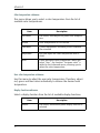
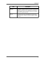
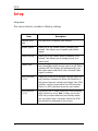
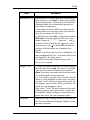
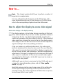
MDSC-1119-2124
Online User Guide
(This page intentionally left blank.)
2
Where to get more information
Where to get more information
Where to find more information
The following documentation is included with your system:
Document
Location
Information
Getting started
guide
Booklet in box
Booklet describing how to
install and setup the display
Getting started
guide (PDF)
CD-ROM
The same booklet in PDF format
Online user
guide (PDF)
CD-ROM
User guide in PDF format,
describing how to use the onscreen display menus and
functions
RS-232 manual
(PDF)
CD-ROM
Manual describing the RS-232
protocol
3
On-screen display (OSD)
On-screen display (OSD)
To use the OSD menu system:
1. When the display is on and the OSD is not on the screen, touch the
Enter
soft touch key.
The front illumination is switched on for about 10 seconds.
2. To display the main menu, touch the Enter
the illumination is on.
touch key while
The OSD main menu appears. Several menu items contain
submenus.
MDSC-1119
Input Selection
Adjustments
PiP
User Profile
More...
Exit
Figure 1: Main menu
Note: Some of the menu items described in this manual may not
be available on your display, depending on the selected video
input.
3.
To scroll through the menu, use the navigation keys or .
The corresponding submenus are displayed automatically. The red
scroll bar indicates the active menu item.
4. To jump into a submenu while it is displayed, press the Enter
touch key.
The red scroll bar now appears in the submenu.
4
On-screen display (OSD)
5. To exit from a submenu, use the navigation keys
select EXIT. Next, press Enter .
or
to
If you exit from the Main Menu, you exit the OSD.
6. To change an adjustment value or setting, use the navigation
keys or to select the adjustment or setting. Next, press Enter
to go into edit mode. This is indicated by the scroll bar turning
gray and the adjustment bar turning red.
Use the navigation keys
to confirm the change.
or
to change the value. Use Enter
Changes are saved automatically when you exit from the OSD.
Tips:
While you are adjusting a value:
• Touch
value.
and
at the same time to reset to the factory-default
• Touch first and then
minimum value.
while still holding
to select the
• Touch first and then
maximum value.
while still holding
to select the
While navigating in the OSD submenus:
• When any non-adjustable or name change menu item is
selected, pressing the Enter
key for a long time closes the
OSD while saving the changes.
When the display is in stand-by, touch and hold the Stand-by
soft touch key for about 2 seconds until the display switches on.
To switch the display back in stand-by, touch and hold the Standby soft touch key until the display switches off.
5
Input selection
Input selection
The MDSC-1119/MDSC-2124 can be equipped with numerous different
video inputs. The available inputs may depend on the customer’s
requirements.
Input selection can be done in 5 ways:
• Automatically, by means of the Source Scan system
• By assigning a source priority
• Quick input selection by using the general purpose switch.
• Quick input selection by using the navigation keys without
entering the OSD.
• Using the Input selection menu in the OSD.
These 5 possibilities are described more in detail below.
Source scan
Source scan is a system that automatically scans all video inputs in the
display until it detects a correct video signal at one of the inputs. When
that video signal disappears again, the source scan system
automatically starts again, looking for another video signal.
The source scan system can be enabled or disabled in the Setup menu.
Source priority
In the Setup menu you can give priority to an input source. If a priority
has been established, the display will automatically select this source if
a signal is present on this input. The priority input selection will overrule
the manual input selection. For more information, please refer to
“Setup” on page 24.
6
Input selection
Quick input selection
You can quickly select another video input as follows:
1. Make sure the OSD is not on the screen. If it is, exit the OSD.
2. Touch the navigation keys or . The illumination is switched on
and the current video input is displayed.
3. While the illumination is on, touch the navigation keys
select another video input.
or
to
The quick input selection feature can be enabled/disabled in the Setup
OSD menu.
General purpose switch
If switches are connected to the display GPIO connector, you can use
them to switch inputs quickly. For this purpose, the GPIO input function
must be enabled in the Setup menu.
7
Input selection
Input selection menu
In this OSD menu, select the desired video input source from the list of
input sources.
The possible inputs are:
Input
Description
VGA
Analog video on Sub-D15 connector
Grayscale
Analog monochrome video signal connected to
the G BNC connector
RGBS
Analog video signals connected to the BNC connectors
S-Video1
S-video signal (separate Y/C) on SVHS connector
S-Video2
S-video signal (separate Y/C) on BNC connectors: Y on connector G, C on connector B
YPrPb
Component video (Yuv) signals on BNC: Y on
connector G, Pr on connector R, Pb on connector B
CVBS1
Composite video signals on BNC R connector
CVBS2
Composite video signals on BNC G connector
CVBS3
Composite video signals on BNC B connector
Standard & HD-SDI
Standard & High-definition serial digital video
connector
DVI digital
DVI digital signals on DVI connector
DVI optical
4-wire input
Test Pattern
Allows to switch on the internal test pattern
generator
Some of the inputs that are built-in in the display may not be
visible in the source scan, quick input selection menu or input selection
Note:
8
Input selection
menu. They may be disabled in the Setup menu. See Setup, on
page 24.
Note: It can be that some of the inputs listed above can not be enabled
for your specific display configuration. For an overview of the possible
configurations, consult the connectors paragraph of the Getting Started
Guide.
Alias names
You can add alias names to the available inputs to make it easier for the
user to know what video source is connected to which input. E.g., if an
endoscopic camera is connected to the S-Video1 input, you can add the
alias ‘Endoscope’ to the S-Video 1 input.
To enter an alias name:
1. Select the desired input in the Input Selection menu.
2. Press
line.
for a few seconds, until ********** is added to the menu
3. Now use
4. Use
and
to select the first character.
to go to the next character.
5. Repeat steps 3 and 4 to make the alias name.
6. Use to delete the last entered character (like backspace on a
computer keyboard).
7. When the alias name is completed, you must use
* is cleared.
8. To cancel the text edit without saving, press
seconds.
and
until the last
for 2
The alias names will appear in the Input Selection, Source Priority and
Enable Inputs menus, but only in the Input Selection menu you can
define or change them.
9
Adjustments
Adjustments
Adjustments menu
In this menu you can perform a number of image adjustments.
Note: When picture-in-picture (PiP) is active, the adjustments
will affect the PiP1 video frame only. If you wish to adjust the
video signal in the PiP2 frame, toggle the PiP frames in the PiP
menu so that the signal from frame2 is displayed in frame1. Then
make the adjustments (the PiP2 frame disappears while in
Adjustment menu) and finally toggle the PiP frames again.
Item
10
Description
Brightness
Adjusts the image brightness. This means all luminance levels from black to white are adjusted.
Brightness and contrast are factory-adjusted to
obtain a maximum dynamic range.
Contrast
Adjusts the image contrast. This means the black
level remains constant and the white levels are
adjusted, changing the luminance difference
between black and white.
Brightness and contrast are factory-adjusted to
obtain a maximum dynamic range.
Color
Adjusts the color saturation.
Hue
Adjusts the hue. Do not use the Hue adjustment to
change the image color temperature. The Hue
adjustment is applicable only to correct phase
errors in NTSC video sources. This is an adjustment
for advanced users.
For color temperature adjustment, refer to the
Advanced menu.
Adjustments
Item
Description
Noise reduction
Adjust this in case the selected video source
exhibits unwanted noise. Note that this adjustment reduces noise but also reduces image sharpness.
Sharpness
Adjusts the image sharpness.
Autosetup
Takes you to the autosetup submenu (see below)
Restore Current
Preset
Takes you to the restore current preset submenu
(see below).
Scaling
Takes you to the scaling submenu (see below).
Adjust scaling
This function is visible only when Adjustable scaling is selected.
Use this function to adjust the scaling manually.
The picture size will be controlled proportionally.
Aspect ratio
Takes you to the aspect ratio submenu (see
below).
Adjust Aspect
Ratio (ASR)
This function is visible only when Adjustable
aspect ratio is selected.
Use this function to adjust the aspect ratio manually. The picture width will be controlled whereas
the picture height remains unchanged. To adjust
picture height as well, you must adjust Scaling.
Autosetup submenu
Use this menu to perform an automatic adjustment. This menu is
available only when an analog video input is selected.
There are 4 different ways to perform an autosetup.
It is very important to display a proper test pattern while performing
these functions. The requirements for the test pattern are described in
the table below.
11
Adjustments
Tip: You can find a suitable test pattern on the product CD-ROM.
Item
Description
Full
Performs the combination of phase, geometry and
gain offset setup
Phase
Automatically adjusts panel phase.
For a correct adjustment, the image must contain
fine details, such as small characters.
Note that Phase adjustment may not have any
effect on some input types.
Geometry
Automatically adjusts image geometry.
For a correct adjustment, the image must be completely filled up to the edges, and the video level
at the edges must be at least 15% of the full
video amplitude.
Gain offset
Automatically adjusts gain offset.
For a correct adjustment, the image should contain pure black and white elements. These elements should appear in a central part of the
image, at a distance of at least 2 cm from the
edges.
Next preset
Selects the next video timing stored in the memory. See See About video timings in the display
memory, on page 31 for more information about
video timings.
Restore Current Preset submenu
Use this menu to restore the current preset.
The current preset is the set of display parameters related to the
selected input and video timing and contains all settings of that specific
input and video timing and can be adjusted via the menu. Changed
image settings are automatically saved when exiting the menu, except
for luminance, which is a global parameter.
12
Adjustments
Scaling submenu
This menu allows you to set the image scaling.
Item
Description
Native
The image is not scaled. The image is displayed at
the LCD panel’s native resolution.
Best fit
The image is scaled proportionally to obtain the
best fit.
Fit height
The image is scaled proportionally so that the
image height fits the LCD panel height
Fit width
The image is scaled proportionally so that the
image width fits the LCD panel width
Full display
The image is scaled non-proportionally so that the
image height and width fit the LCD panel height
and width. This is not a recommended selection in
most cases.
Adjustable
When you select Adjustable, the function “Adjust
scaling” is added to the Adjustments menu. Use
this function to scale the image as desired.
Aspect ratio submenu
In this menu you can select the image aspect ratio: 1/1 (square), 4/3,
5/4, 16/9, Auto or Adjustable.
When set to Auto, the display automatically selects the best suitable
aspect ratio based on the timing or resolution of the incoming video
signal. This is the recommended setting.
When set to Adjustable, the function Adjust Aspect Ratio appears in the
Adjustments menu. Use this function to adjust the aspect ratio
manually. Use this function if the Auto setting does not give the desired
result.
13
PiP
PiP
PiP (picture in picture) menu
This menu lets you select layout, video sources and other setting for the
PiP function.
The PiP function allows to view two video sources on one display. They
are displayed in 2 different frames.
Note: The PiP menu is not available when a priority input source
is selected. See also “Source priority” on page 6.
Item
14
Description
Select PiP layout
You can select a Picture-in-Picture layout from a
list of pre-defined layouts.
A PiP layout determines the video inputs, size,
position, scaling and aspect ratio for both PiP
frames.
PiP input 1
Takes you to the PiP input submenu (see below)
for PiP frame 1.
PiP input 2
Takes you to the PiP input submenu (see
below)for PiP frame 2.
Size
Adjusts the size of the PiP frame (1 or 2).
Depending on the aspect ratio of the corresponding video input (see “Aspect ratio submenu” on page 13), the maximum size may be
smaller than 100%: The maximum size is
reached when the PiP frame reaches the full
screen width, even when the frame vertical size
is still smaller than the screen height.
H Pos
Adjusts the horizontal position of the PiP frame
(1 or 2)
V Pos
Adjusts the vertical position of the PiP frame (1
or 2)
PiP
Item
Description
Border
Takes you to the border color submenu (see
below). The border is not available when the PiP
frame size is maximum.
PiP order
Touch Enter
to change the stacking order of
the PiP frames
Toggle PiP
Touch Enter
to switch the video sources of
both PiP frames. The Reversed state is the situation where the input source for PiP2 is switched
to PiP1.
PiP layout name
Allows you to change the PiP layout name.
To change the name, press
for a few seconds
until the name in the menu changes to
**********. Now use
and
to select the first
character. Use
to go to the next character.
Use
to delete the last entered character (like
backspace on a computer keyboard).
When the name you wish to use is completed,
you must use
until the last * is cleared and
the new name appears in the menu.
To cancel the edit without saving, press
and
for 2 seconds.
Store layout
Touch Enter
to store the changes to the current PiP layout
Delete layout
Touch Enter
to delete the current PiP layout
PiP input selection submenu
This menu is not available when PiP Off is selected.
For each PiP frame you can select a video input source from the list of
enabled inputs. Some inputs may not be available for PiP2 if they are
not compatible with the selected input for PiP1.
Note:
Video inputs can be enabled/disabled in the Setup menu.
15
PiP
PiP border color submenu
For both PiP frames you can select the border color.
This function is not available when the image is at maximum size. Note
that maximum size may be less than 100% for some images,
depending on the available bandwidth.
16
User Profile
User Profile
User profile menu
In this menu you can create, select, rename and delete user profiles. A
user profile stores the display settings the user has made for a certain
video signal (characterized by the video timings and the physical input
it is connected to).
When that same video signal is connected to the same input and the
corresponding saved user profile is selected, the display settings stored
in that profile will automatically be used.
Item
Description
Select profile
Lets you select a profile, if already created.
Show profile
settings
Displays a list of all the settings stored in the
selected profile.
Profile name
Lets you rename the selected profile.
To change the name, press
for a few seconds
until the name in the menu changes to **********.
Now use
and
to select the first character.
Use
to go to the next character. Use
to
delete the last entered character (like backspace
on a computer keyboard).
When the name you wish to use is completed, you
must use
until the last * is cleared and the new
name appears in the menu.
To cancel the edit without saving, press
and
for 2 seconds.
Delete profile
Lets you delete the selected user profile.
17
User Profile
Item
Store profile
18
Description
Lets you store a profile. When you have made
changes in the settings of the selected user profile, you must select this function to store the
changes in the profile.
You can store them in the current profile or as a
new profile.
More...
More...
Where More... is displayed in the OSD, some advanced menu items are
hidden. To unhide them, use
unhide the menu items.
and
to select More... Touch
to
19
Advanced
Advanced
Advanced menu
This menu lets you perform some advanced functions.
Item
20
Description
Luminance
Adjusts the display luminance. Use this function if
you experience the overall image is too dark or
too bright.
This function controls the LCD panel backlight. For
more information, see page 35.
Phase
Adjusts the analog video sampling phase (see
below).
Frequency
Adjusts the analog video sampling frequency (see
below).
Color temperature
Takes you to the color temperature submenu (see
below).
Customer color
This function is visible only when the User color
temperature is selected. It allows you to adjust
the color temperature using sliders for R,G and B.
Color adjustment
This function is visible only when the Adjustable
color temperature is selected. It allows you to
adjust the color temperature using a slider.
Display function
Takes you to the display function submenu (see
below).
Gamma
Adjusts the display gamma. This function is visible
only when the Gamma display function is
selected.
Advanced
Item
Description
Restore factory
settings
Touch Enter
, which opens a submenu.
Touch
or
to select Yes and touch
to
restore the factory settings.
As a consequence all user settings, including the
user presets and user profiles, will be erased and
the display will restart.
To adjust the phase:
Note: Before adjusting the phase, adjust the frequency (see
below).
1. Display a dot on-dot off test pattern.
Tip: You can find a suitable test pattern on the product CD-ROM.
2. Adjust the phase so that the test pattern appears as bright as
possible and is completely free of noise and moving lines.
To adjust the frequency:
1. Display a dot on-dot off test pattern.
Tip: You can find a suitable test pattern on the product CD-ROM.
2. In the Adjustments menu, Scaling submenu, select Fit width.
3. As you adjust the frequency you will notice dark vertical bands
appearing in the image. Adjust the frequency so that the test
pattern is completely free from vertical bands and interferences.
It may be necessary to repeat Phase and Frequency adjustments to
obtain the best result.
21
Advanced
Color temperature submenu
This menu allows you to select a color temperature from the list of
available color temperatures.
Item
Description
Full white
The native, unchanged LCD panel color temperature
6500K
Color temperature of 6500 Kelvin.
ClearBase
A color temperature according to the clearbase
film standard
Adjustable
Lets you adjust the color temperature with a
slider.
User
A user-definable color temperature. When you
select “User”, the function “Customer color” is
added to the Advanced menu, allowing you to
adjust the color temperature.
User color temperature submenu
Use this menu to adjust the user color temperature. Therefore, adjust
red, green and blue colors individually to achieve the desired color
temperature.
Display function submenu
Select a display function from the list of available display functions:
Item
Native
22
Description
The native, uncorrected panel display function is
selected.
Advanced
Item
Description
Gamma
A gamma display function is selected. Use this setting if you wish the color behavior to resemble a
CRT display. You can manually adjust the gamma
with the Gamma function.
DICOM
A display function according to the DICOM standard. Use this setting for DICOM-compliant applications.
23
Setup
Setup
Setup menu
This menu contains a number of display settings.
Item
24
Description
Camera selection
Lets you select a camera (see below).
Enable inputs
Takes you to the Enable inputs submenu (see
below). This allows you to enable and disable
inputs.
Source priority
Takes you to the Source priority submenu (see
below). This allows you to assign priority to a
video input.
Source scan
Use Enter
to switch source scan on or off. When
switched on, the display will automatically scan
the video inputs and check if the selected video
signal is present.
GPIO interface
(1/2)
Takes you to the GPIO (General Purpose Input-Output) function submenu to define the behavior of
the general purpose switch (see below). Two GPIO
switches can be connected to the GPIO interface.
There is a GPIO interface menu for each switch.
GPIO position
(1/2)
This menu line is visible when the corresponding
GPIO function is set to Text. It takes you to the
GPIO text position submenu (see below) where
you can select from 6 locations where the GPIO
text should be displayed on the screen.
Setup
Item
Description
GPIO text (1/2)
This menu line is visible when the corresponding
GPIO function is set to Text. It allows you to define
the text (maximum 10 characters) that should be
displayed when the corresponding general purpose switch is depressed.
It also takes you to the GPIO Icon submenu (see
below) where you can select from 4 pre-defined
icons to accompany the GPIO text.
To edit the text, press
for a few seconds while
GPIO text is selected, until the GPIO text in the
menu changes to **********. Now use
and
to select the first character. Use
to go to the
next character. Use
to delete the last entered
character (like backspace on a computer keyboard).
When the word you wish to use is completed, you
must use
until the last * is cleared and the new
text appears in the Setup menu.
To cancel the text edit without saving, press
and
for 2 seconds.
Trigger (1/2)
This function defines how the GPIO switch triggers
the selected action. Level: The action is executed
each time the switch is depressed or released.
Pulse: The action is executed each time the switch
is first depressed and then released.
E.g., The switch is a pedal switch and the selected
action is a text displayed on the screen. You have
selected “Level”. When you depress the pedal, the
text appears on the screen. When you release the
pedal, the text disappears again.
Next, select “Pulse”. When you depress the pedal,
nothing happens. When you release it again, the
text appears. When you depress and release the
pedal once more, the text disappears again.
Language
Takes you to the Language submenu, allowing you
to select the OSD menu language: English, French,
German or Spanish.
25
Setup
Item
26
Description
OSD timeout
Takes you to the OSD timeout submenu (see
below).
RS232 baudrate
Takes you to the RS232 baudrate submenu (see
below).
Quick input
selection
Use Enter
to enable or disable the quick input
selection feature. When enabled, you can use the
navigation keys
or
to switch inputs while no
OSD is on the screen.
Power LED
Use Enter
to switch the (green) power LED on
or off. The (orange) stand-by LED is not influenced.
Power save
Use Enter
to switch the power save system on
or off. When switched on, the display will automatically switch off when the connected video
signal falls away (e.g., computer goes in standby).
User controls
Use Enter
to switch the user controls on or off.
When switched off, the user controls cannot be
used to display and use the OSD.
When the user controls are disabled, you can
enable them again by pressing the
and
keys
simultaneously for 5 seconds. Then navigate to the
Setup menu and switch User controls on again.
OSD menu
Use Enter
to disable/enable the OSD. When
disabled, the OSD will not appear when touching
the control keys. Only the quick input selection
and stand-by functions are enabled.
When the OSD is disabled, you can enable it again
by pressing the
and
keys simultaneously for
5 seconds. Then navigate to the Setup menu and
switch OSD menu on again.
Key Sound
Use Enter
to disable/enable the key sound (a
short beep sound) when touching the user control
panel keys.
Setup
Camera selection
This submenu lets you select from a list of camera types. The selection
provides customized settings for certain timings, as requested by the
selected camera.
Enable inputs
When you open this submenu, the list of all video inputs the display
contains, is shown. You can decide to disable some of these inputs by
using the
key.
A disabled input is not shown in the Input selection menu, nor is it
taken into account for the quick input selection, source scan system or
GPIO input switching.
When a video input is enabled, there is a check mark after its name in
the Enable inputs submenu.
Source priority
To assign priority to a video input, select the desired input from the list.
The list contains all available inputs that do not conflict with the
currently selected input source.
To disable source priority, select None.
Note: When a priority input is selected, Picture-in-Picture (PiP) is
no longer possible. The PiP menu will not be available in the OSD.
The video input to which priority is assigned, has priority over all
the other connected video sources. If that video signal is present at
its input connector, the display will automatically select that input.
If the priority signal is not present, the display will start an
autoscan and select the next input where a signal is present.
While the priority signal is present, you can still temporarily select
another input by means of the Input selection menu. However
when you exit the menu, the display automatically selects the
priority input again.
27
Setup
OSD timeout
Select the desired OSD time-out from the list of available time-outs.
When selected, the OSD will automatically disappear when the display
controls are left idle for the time selected from the list.
GPIO function
From the list of available entries, select the desired behavior of the
general purpose switch:
Item
Description
Disabled
Nothing happens when the GP switch is
depressed
Input
The display browses through the selected video
inputs while the GP switch is being depressed
Text
A text is displayed when the GP switch is
depressed. You can define this text by using the
GPIO text function.
PIP order
When you press the GPIO switch, the stacking
order of the PiP frames changes.
GPIO text position
From the list of possible text positions, select the position where you
wish the text to be displayed when the GP switch is depressed.
GPIO icon
From the list of possible icons, select the icon you wish to accompany
the text that is displayed when the GP switch is depressed.
If you select None, the GPIO text will be displayed without any icon.
28
Setup
Baudrate submenu
Select the proper baudrate from the list of available baudrates. This is
important for data communication via RS-232. You should select the
proper baudrate that matches the data source baudrate.
29
Information
Information
Information menu
In this menu you can consult information about the display. When PiP is
enabled, the information displayed refers to PiP1 only.
Item
30
Description
Show current
setup
Opens a submenu where you get a list of all the
current settings
Product
The name (type) of the display
Order code
The Barco display order number
Serial number
The display serial number
Run
The version of the run code
Display runtime
The number of hours the display has been operating, including stand-by position.
Backlight runtime
The number of hours the LCD panel backlight has
been operating. This is the time the display was
on while not in stand-by.
RS232 baudrate
The current RS232baudrate
Timing information
The current video signal timing information is
listed: Resolution, vertical frequency, horizontal
frequency, pixel clock frequency and whether it is
locked or not
How to....
How to....
Note: This chapter explains briefly how to perform a number of
important or complex tasks.
For more information about how to use the OSD menus and a
more detailed description of all the functions in the OSD, please
refer to the corresponding chapters about the OSD menus.
How to adjust the display to a new video signal
About video timings in the display memory
The display contains a list of video timings according to VESA and
other video standards. If you connect a video signal that matches a
timing from the list, it is adjusted automatically according to a
number of parameters that are defined in the list. If the connected
video signal has a timing that is not in the list, the display selects
the timing from the list with the closest match and also adjusts the
signal according to the corresponding parameters.
If the user makes any additional adjustment, the video signal
(with its adjustments) is stored as user preset. The next time this
video signal is connected and selected, the display recognizes it as
one of the user presets and reproduces it with the corresponding
adjustments. The signal is recognized by its timing and the type of
video input it is connected to. This means a certain video signal
connected to the VGA input or to the BNC inputs can be stored as
two different user presets.
Additionally you can store a user preset as User Profile and give it
a name. For more information, please refer to “User profile
menu” on page 17.
Note that camera selection may change some of the settings for
certain input timings, depending on the requirements for the
selected camera. The camera selection will affect the user preset,
but will never affect a user profile.
31
How to....
The display memory can contain maximum 20 different user
presets. When the memory is full, the last user preset is
overwritten when a new video signal is adjusted.
When Restore Factory Settings from the Advanced menu is
selected, all the user settings, including the user presets, are
cleared.
To adjust the display to a new video signal:
a) Digital video signals:
Normally a digital video signal (on SDI or DVI-digital input) needs no
additional adjustment. If desired, you can change the color temperature
or display function in the Advanced menu. You can also perform an
Autosetup in the Adjustments menu, but only geometry will be
adjusted.
b) Analog video signals:
An analog video signal may require some adjustments the first time it is
connected.
Note: If an analog video input is selected, you can perform
Autosetup in the Adjustments menu, automatically adjusting
phase, geometry and gain offset.
If Autosetup is not available or does not give satisfactory results,
proceed as follows:
1. Display a dot on-dot off test pattern.
Tip: You can find a suitable test pattern on the product CD-ROM.
2. In the Advanced menu, adjust Phase.
3. In the Advanced menu, adjust Frequency.
4. In the Adjustments menu, adjust Brightness, Contrast, Color, Hue
and Sharpness, if necessary.
5. Also in the Adjustments menu, adjust Aspect Ratio and Scaling, if
desired.
32
How to....
How to make a PiP setup
Setting up picture-in-picture
Picture-in-Picture (PiP) is a feature where two different video signals
can be displayed next to each other or on top of each other in 2
separate frames. You can adjust the way in which the video signals are
displayed and store this in a PiP layout.
The display has a number of predefined PiP layouts that can be
modified by the user. A PiP layout determines the video input, size,
position, scaling and aspect ratio for both PiP frames.
Note: The PiP menu is not available when a priority input source
is selected. See also “Source priority” on page 6.
To change a PiP layout, proceed as follows:
1. In the PiP layout submenu, select one of the PiP layouts from the
PiP layout submenu. Beware that you will overwrite this layout.
2. Select the desired PiP1 input from the list of available video input
sources.
3. If you wish to change the aspect ratio of the PiP frame, exit the PiP
menu and go to the Adjustments menu to change Aspect Ratio.
This will affect the width of the frame only.
Note: While the Adjustments menu is open, PiP2 frame will not
be visible. It appears again when you exit the Adjustments menu.
4. In the Adjustments menu you can also adjust brightness,
contrast, color, hue and sharpness as desired for the signal
displayed as PiP1.
5. Go back to the PiP menu and adjust Size (scales the PiP frame
proportionally), H Pos and V Pos for PiP1.
6. If desired, select a border color for the PiP1 frame.
33
How to....
7. Select the desired PiP2 input from the list of available video input
sources. See also the note below.
Note: When selecting the video input for PiP2, some inputs may
not be available, depending on the chosen PiP1 input.
8. If you wish to adjust the image in the PiP2 frame, select Toggle
PiP. As a consequence, the video signal from PiP2 now becomes
PiP1. This is necessary because the functions in the Adjustments
menu always affect the image in PiP1 only.
9. Go back to the Adjustments menu and adjust aspect ratio,
brightness, contrast, color, hue and sharpness as desired like in
steps 3 and 4.
10. Go back to the PiP menu and select Toggle PiP again to switch the
second video signal back to PiP2 again.
11. Adjust Size (scales the PiP frame proportionally), H Pos and V Pos
for PiP2.
12. If desired, select a border color for the PiP2 frame.
13. If necessary, select PiP order to change the PiP stacking order.
14. If desired, select PiP layout name to change the name of the PiP
layout.
15. Select Store layout to save the changed layout in the memory.
Note: It is possible to select the same video input for both PiP
frames. However, it is difficult to give them different image
adjustments, as both frames will get the same adjustments every
time you select Toggle PiP.
34
How to....
How to use brightness, contrast and luminance
adjustments
Although they may seem very similar, there is quite a difference
between brightness, contrast and luminance adjustments.
• Luminance adjustment leaves the video signal untouched but
changes the light intensity of the backlight behind the LCD panel
inside the display.
• When controlling brightness, all video levels from black to
white are adjusted. You should adjust brightness to make the
black parts of the image perfectly black. But watch out not to
decrease brightness too much (avoid losing information in the
dark parts of the image).
• When controlling contrast, the black level remains constant and
the white levels are adjusted, changing the luminance
difference between black and white. You should adjust contrast
after brightness has been adjusted, to make the white parts of
the image perfectly white. But watch out not to increase
contrast too much (avoid losing information in the bright parts
of the image).
Important: If you adjust brightness and contrast incorrectly, clipping of
the video signal may occur: When brightness or contrast is too high, you
may lose information in the bright parts of the image because the image
is too bright. When brightness is too low, you may lose information in the
dark parts of the image because the image is too dim.
Some suggestions:
• If you experience the image is too dim, increase the contrast so
that no clipping occurs (no information lost in the bright parts).
Next, increase luminance slightly, if desired.
• If you experience the image is too bright (clipping occurs in the
bright parts) decrease contrast until the clipping is solved.
Luminance adjustment will not have any effect here.
35
How to....
How to adjust color temperature
The MDSC-1119/MDSC-2124 display contains 3 pre-defined and 1 userdefined color temperatures. You cannot adjust color temperature
separately for the 2 picture-in-picture frames. It can be adjusted only for
the whole display.
To adjust color temperature:
1. Open the OSD and select menu Advanced.
2. Select submenu Color temperature.
3. Select one of the pre-defined color temperatures or select
Adjustable or User.
4. If you selected Adjustable, return to the Advanced menu and
adjust the slider in the Color Adjustment function.
5. If you selected User, return to the Advanced menu and select
Customer color.
6. In the submenu, for red, green and blue separately, adjust the
intensity from 0 to 100 %.
36
How to....
37
K5904074-05
Sept 2010
Barco n.v.
President Kennedypark 35
8500 Kortrijk
Belgium
www.barco.com