1
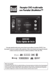
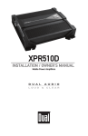
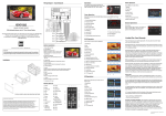
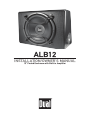
ALB12
INSTALLATION/OWNER'S MANUAL
12" Ported Enclosure with Built-in Amplifier
PREPARATION
Getting Started
Thank you for purchasing the Dual ALB12 12" ported enclosure with built-in
amplifier. Although Dual has attempted to ensure the information in this manual
is accurate, please be aware that any part of it is subject to change without notice.
Please read entire manual before installation. Due to the technical nature of
amplifiers, it is highly recommended that your Dual ALB12 is installed by a
professional installer or an authorized dealer.
Before You Start
•Always disconnect the negative battery terminal. Consult a qualified technician
for instructions if you are unsure.
•Avoid installing the amplifier where it would be subject to high temperatures,
such as from direct sunlight, or where it would be subject to dust, dirt or
excessive vibration.
•Use extreme caution when drilling holes to avoid damaging fuel lines or
existing vehicle wiring. •All amplifier installations require power, signal and speaker wires (not
included).
•An amplifier installation kit (sold separately) is highly recommended to
facilitate the installation. Consult your dealer for recommendations. Mounting Location
•Choose a mounting location for the ALB12. Suggested locations include behind
a seat or in the trunk.
•For optimum performance, make sure to provide at least 1" of space around all
sides of the amplifier.
•Do not mount the ALB12 under carpets or where airflow is restricted.
•Do not install the ALB12 where it may be exposed to moisture.
•The optimum mounting location varies between vehicles. Remember to test all
amplifier functions before completing the final mounting procedure.
2
INSTALLATION
Safety First
!
CAUTION
The following instructions are designed to ensure safety during installation and
use of the ALB12. Failure to heed these instructions can result in injury or damage
to the unit or vehicle.
The following installation instructions are intended to be used as a basic
guideline. If you feel unsure about installing this speaker system yourself, Dual
recommends acquiring the services of a professional car audio installation
center.
Before installation, please review the following guidelines:
1. Be sure to carefully read and understand the instructions before attempting to
install this product.
2. If additional wiring is required, we recommend running all wires prior to
mounting your enclosure in place.
3. To ensure reliable performance and minimize signal or power loss, use the
highest quality connectors available.
4. Never run speaker wires underneath your vehicle. Running speaker wires
inside the vehicle provides the best protection from exhaust, heat and
environmental elements.
5. Avoid running wires over, near or through sharp-edged surfaces. We suggest
you also use rubber grommets to protect any wires routed through metal,
especially the firewall.
6. When running the speaker cable to the amplifier, avoid running it near sources
of high current (i.e. wiring harnesses, battery cables).
3
INSTALLATION
Connection Descriptions
Note: Be sure to follow specific instructions included with your amplifier
installation kit (not included with this amplifier). The information below should be
used a general guideline only.
Power Wire (+12V)
•Disconnect negative battery terminal before proceeding. Consult a qualified
technician for instructions if you are unsure.
•Plan wire routing before cutting any wires to length. Begin by routing the power
+12V wire from the battery to the amplifier location. Use a grommet when
running wires through the firewall or metal openings. Avoid running the power
wire near existing vehicle wiring to prevent induced noise from entering the
audio system.
•Use extreme caution when drilling holes to avoid damaging fuel lines or
existing vehicle wiring. •The +12V wire MUST be fused within 18" of the battery for protection of the
vehicle’s electrical system.
Ground Wire (GND)
•The amplifier ground wire should be as short as possible. Choose a clean
unpainted section of metal or the vehicle chassis when attaching the ground
connection. Be sure to clean the area of any dirt or grease.
Remote Turn-on Wire (REM)
•The remote turn-on wire connects to the head unit's amplifier turn-on lead or
other switched 12 volt source.
Input Signal
•The amplifier's input signal connects to the head unit's low level (RCA) outputs.
CAUTION
•Never run any wires underneath or outside the vehicle.
4
INSTALLATION
Connections and Controls
1
2
3
4
5
6
7
8
9
10
1
Line In (Left)
6
Power Indicator
2
Line In (Right)
7
Ground Connection
3
Crossover Frequency
8
Remote Connection
4
Input Level Control
9
Power Connection
5
Phase Control
10 Fuse (15A)
5
INSTALLATION
Typical Wire Routing
BATTERY
Main Power Connections
Connect BAT+, GND and REM wires accordingly. A suitable fuse MUST be installed on the
BAT+ lead within 18" of the battery for protection of the vehicle’s electrical system.
Fuse Rating
When replacing the fuse, make
sure new fuse is the correct type
and amperage. Using an incorrect
fuse could damage the amplifier.
The ALB12 uses (1) 15 amp ATO
style fuse.
6
Power/Ground Wire Size
For optimum performance, use only
12 gauge wire or larger. Make sure
to use the same size power and
ground wire.
INSTALLATION
Control Setup and Adjustment
Input Signal Connections
Low Level (RCA)
Crossover Frequency
Control
Phase Control
Low level (RCA) input signal is preferred for best
performance. Typical trunk-mount installations
require a 17-20 foot RCA cable. Most trucks and
behind-seat applications require a 6-12 foot RCA
cable. Using twisted pair construction RCA cables
will minimize noise.
The adjustable crossover is used to filter out
frequencies above 40Hz ~ 160Hz. Adjust it to where
the ALB12 sound output blends with the rest of the
sound system.
The phase control compensates for delay between
the ALB12 output and the rest of the sound system.
Begin with the phase control set to 0 degrees. If
the sound is adequate from the normal listening
position inside the vehicle, no further adjustment is
necessary. If the sound is thin or lacking bass, adjust
the phase control until the bass is full and punchy.
Input Level Control
The input level control (LEVEL) is used to obtain the
best possible match between the head unit audio
output and the amplifier input. Begin by turning
the input level control fully counterclockwise. Next,
turn up the head unit volume control around 3/4 of
the way up. Adjust the input level control clockwise
until audible distortion is heard, then slightly
counterclockwise to provide the best match.
LED Indicator
The LED indicator illuminates green during normal
operation.
7
INSTALLATION
Troubleshooting
Problem
Cause
Unit will not turn on
(no power LED indicator)
BAT+ wire not connected or incorrect voltage
REM wire not connected or incorrect voltage
Check connections for proper voltage
(11~16VDC)
GND wire not connected
Check connection to ground
Fuse(s) blown
Replace fuse(s)
Volume turned all the way down
Increase volume level at head unit
Speaker defective or damaged
Check/replace speaker
Input signal not connected
Check high or low level inputs for
proper connection
Unit has power - LED is
green (but no sound)
Unit blows fuse(s)
Incorrect fuse rating
Use fuse(s) with correct rating
BAT+ wire touching chassis ground
Check for pinched wire
Speaker defective or damaged
Check/replace speaker
Bad ground connection
Make sure amplifier is grounded to
clean bare metal
Signal ground loop or RFI (radio frequency
interference)
Re-route RCA cables from existing
high current wiring
Distorted audio output
Incorrect input signal type or
input level too high
Check connections and reduce/adjust
input level
Low audio output
Incorrect input signal type or
input level too low
Check connections and increase or
adjust input level
Low frequency output is out of phase
Adjust phase control as needed
Engine noise
Weak bass
8
Action
WARRANTY
Limited One-Year Warranty
This warranty gives you specific legal
rights. You may also have other rights
which vary from state to state.
Dual Electronics Corp. warrants this
product to the original purchaser to be free
from defects in material and workmanship
for a period of one year from the date of
the original purchase.
Dual Electronics Corp. agrees, at our
option, during the warranty period,
to repair any defect in material or
workmanship or to furnish an equal
new, renewed or comparable product
(whichever is deemed necessary) in
exchange without charges, subject to
verification of the defect or malfunction and
proof of the date of purchase. Subsequent
replacement products are warranted for
the balance of the original warranty period.
Who is covered? This warranty is extended
to the original retail purchaser for products
purchased from an authorized Dual dealer
and used in the U.S.A.
What is covered? This warranty covers all
defects in material and workmanship in
this product. The following are not covered:
software, installation/removal costs,
damage resulting from accident, misuse,
abuse, neglect, product modification,
improper installation, incorrect line voltage,
unauthorized repair or failure to follow
instructions supplied with the product, or
damage occurring during return shipment
of the product. Specific license conditions
and copyright notices for the software can
be found via www.dualav.com.
What to do?
1. Before you call for service, check the
troubleshooting guide in your owner’s
manual. A slight adjustment of any
custom controls may save you a service
call.
2. If you require service during the
warranty period, you must carefully
pack the product (preferably in the
original package) and ship it by prepaid
transportation with a copy of the original
receipt from the retailer to an
authorized service center.
3. Please describe your problem in
writing and include your name, a
return UPS shipping address (P.O. Box
not acceptable), and a daytime phone
number with your shipment.
4. For more information and for the
location of the nearest authorized
service center please contact us by one
of the following methods:
• Call us toll-free at 1-866-382-5476
• E-mail us at [email protected]
Exclusion of Certain Damages: This
warranty is exclusive and in lieu of any
and all other warranties, expressed or
implied, including without limitation the
implied warranties of merchantability and
fitness for a particular purpose and any
obligation, liability, right, claim or remedy
in contract or tort, whether or not arising
from the company’s negligence, actual
or imputed. No person or representative
is authorized to assume for the company
any other liability in connection with the
sale of this product. In no event shall the
company be liable for indirect, incidental or
consequential damages.
9
INSTALLATION
Notes
For Your Records
Please keep your original sales receipt and be prepared to
provide this receipt in the event you require service, as your
original receipt is considered the best proof of purchase and
indicates the date you purchased your Dual product.
Dealer Name
Dealer Phone
Purchase Date
Register Your Product
10
Register your product online at www.dualav.com
INSTALLATION
Specifications
Maximum Output Power
500 watts
Continuous Output Power
100 watts
Frequency Response
20-200Hz
S/N Ratio @ 1 watt
Input Impedance
85dB
Low level (RCA): 10k ohms
Input Sensitivity (RCA)
50mV – 3V
Crossover Frequency
40–160Hz
Crossover Slope
Phase
Fuse
Dimensions
6dB/octave
0–180 degrees
15 amp ATO
18.9 x 14.17 x 11" (WxHxD)
Design and specifications subject to change without
notice.
11
Dual Electronics Corp.
Toll Free: 1-866-382-5476
www.dualav.com
©2013 Dual Electronics Corp. All rights reserved.
NSA0413-V01
Printed in China