1
Australian Monitor
AM3002
Ausbdlan Monitor
H+,"
-tr'
r;-r
"''.r.. \i"
::7
t:
\:.
;\"/ ,lt_, \\1i. I[ {l
ll
-__:,vi:_.
\-r
LUI
Operation Manual
IMPORTANT!
Please read carefully.
This operation manual containsimponant information regarding
safety precautions, installation, perfomance, operation and
mainlenance of your AM3OO2 power amplifier. You should
familiarize yourself with the contents
manual before operating your amplifier.
of
this
Safety Precautions
and Labelling
The rearpanelofthe unit hasa numberof martingsand
internationally recognized symbols related to the
REFER SERVICING TO
hazards and precautions that should be taken when
operating MAINS connecled equipmenl.
The presenceof a LIGHTNING FLASHwith an aJrowhead
containedwithinthe bounda ries of a n equilateraltriangle
is intended to alertthe userthat dangerous uninsulated
voltages may existwithin the unit's enclosure. These
voltages may be of a sufficient magnilude as to
constilute the risk of an electrical shock.
This symbol is reinforced with the text:
!CAUTION!
RISK OF ELECTRICAL SHOCK
DO NOT OPEN
The presence ofan EXCLAMATION MARKcontained
within the boundaries of an equilateral triangle is
intended
lo alert the
user thal there is important
operaling and maintenance lileraturethat accompanies
the unit.
QUALIFIED PERSONNEL.
NO USER SERVICEABLE
PARTS INSIDE.
The user should not attempt to service the unil. Only
qualified and knowledgeable personnel familiar with
lhe internal wortings of the unit should attempt any
repair, servicing or authorized modification to the
unit. The unit does not contain any parts which the
usercan service orre-use in this orany otherproduct.
lf you are in need of special assistance and the
information you require is outside the scope of this
manual, please contact your nearest service agent or
Australian Monitor direct:
THE TECHNICAL OFFICER
AUSTRALIANMONITOR
Ci-AUDIOTELEXCOMMUNICATIONS PTY LTD
PRIVATE BAG 149,
SILVERWATER. N.S.W. 181 1
AUSTRALIA.
!WARNING!
DO NOT EXPOSE TO EITHER
RAIN OR MOISTURE
The unit should not be operated in a situation where it
may encounterthe entry ofwater, rain, oranyfluids. To
exposelhe unittothe above conditions may makethe
operation ofthe unit hazardous and increase the risk
of electrical shock.
/tu
Phone
lntemational
Fax
(02) 9748-2537
61-2-9647-1411 61-2-9748-2537
Email
lntemet
[email protected]
www.auslralianmonitor.com.au
Local
(02)
9647-1411
Features:
- Custom designed, 3RU heavy duty alloy
- Modular
chassis.
construction.
-Active balanced inputs.
-21 Position detenled attenuators.
- Symmetrical layout - even weight
distribution.
- Massive heat-sink / heat-exchangers.
- Linear, well-regulating, high cunent
powersupply.
- Efficient front to back cooling.
mainslransformer.
- Continuous high powercapability.
- High
efficiencytoroidal
- Double die - Lateral Mosfet Class AB output
- Binding post and Neutrik "Speakon"
stage.
output
connections.
- lnput signal slrapping (loop through)
- Quad, twin speed axial fans.
- Multi-role output fault indication.
- Front and rear carry handles.
- Front and rear mounting points.
-
connectors.
High-quality, close-tolerance components used
throughout.
Protection Features:
turn-on.
- side chain mains swilching control.
- lnput muting at turn-on.
- lnputovervoltage protedion.
- Radio-frequency interference suppression.
- Short-circuit protection and indication.
- Suppression of inrush cumenl at mains
Australian Monitor
-Thermaloverload protection and indication.
- Mains circuit Breaker.
- lndividual high cunent rail
-
breaker.
Layout, grounding, decoupling and componentry
have been oplimized to provide the user with
stability, reliability and longevity.
/tu
-l
Contents
Page
.
2.
1
3.
4.
5.
6.
7.
8.
9.
lntroduction
5
Controls, Connectors and lndicators
6
2.1 Front Panel
7
2.2RearPanel
I
lnstallation
11
Operation
13
Bridge Mode
15
TwoOhmorNotTwoOhm
16
Maintenance
17
Wananty
18
Specification
19
List of Illustrations
Page
/tu
Figure 1. Block Diagram
5
Figure2. Front Panel Layout
6
Figure 3. Rear Panel Layout
I
Figure 4. Case Dimensions
10
Figure 5. "Speakon" Connector Wiring
12
Figure 6. Bridge Mode Speaker Wiring
15
Introduction 5
1.
Introduction
Congratulations on choosing Australian Monitor for
yourprofessional amplifi cation requirements.
The design of your AM3oO2 Audio Power Amplifier
embraces allthe aspecls of a welldesigned unit. The
visual design, mechanical, electrical and sonic
parameters, elong with our dedicated menufacturing
process, have all been optimized to provide a
professional tool that exhibits quality, reliability and
rack mountable unils.
Each channel ofthe amplifier comprises a balanced
active input with an attenuator driving a differential
class A drive stage which in turn drives a fan-cooled,
class AB MOSFET output stage configured as
a
sourcefollower. The unit operatesfrom a high curent
capable linear power supply.
These units have been specifi callydesigned todeliver
longevity.
their high power oulput with minimal distortion, and
provide the critical degree of control required by your
The Al,l30o2 amplifiers are 3 unit (5.25") tall, 19"wide
speakers, at high duty cycles for extended periods.
FNE
AMlP
STAGE
DR VER
OUTPUT
STAGE
SlAGE
.I.
TPLIT
I
I
I
t
+
.H
CH A
OUTPUT
A
(
INPI
T
CH B
OUTPUT
Figure
Australian Monitor
1
Amplifier Block Diagram
/tu
-I
6
Controls & Connectors
2. Controls,
Connectors
&, Indicators
t-
.9
'e
o
=c
.g
E
tin
=
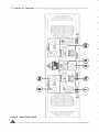
Figure
/tu
2
Front Panel Layout
Controls & Connectors 7
Front Panel
Aft erestablishment of lnrush Currenl Suppression
Figure t shows the panel layout of the AN30O2. The
funclions ofthe controls and indicators are as follows:
l. Attenuator
Level controlforyouramplifier is provided by a 21
position detented potentiomelerand indicates gain
reduction in decibels from the 0 dB position
(maximum gain, no attenualion).
2. VU Meter - Status Indicator
Level Indication
(see
inselt -
showing lhe actual power/volume level available
before clipping (taking mains supply and load duty
into account).
The display is colourcoded, and calibrated in 3dB
increments.
The 10 LEDS are:
=
=
Red =
ln the advent of a thermal overload this LED will
illuminate red indicating that the internaloperating
temperature ofone or both amplifierchannels has
exceeded a safe levelofoperation andthe amplifier
will be shutdown. The fanswill continueto run and
oncethe amplifierhascooled down sufliciently, the
amplifierwill s{art up automatically providing lnrush
Current Suppression and input signal muting until
establishment of the amplifier afler which it will
retum to normaloperating mode.
l)
Each channel featuresa variable 1 0segmentdisplay
Green
Yellow
circuil the LED will extinguish. This LED will not
illuminate during normal use of the amplifier.
-27dBlo-21d8
-18d8 to -6dB
-3dB andthetwo LEDS indicating
the clipping point.
Power On Indication
Two Green LEDS either side of the mains switch
(above the "ON" legend) are used to indicate that
the unit is on. The first Green LED indicatesthe 15
Volt preamp supply is present (the len hand side
display shows -15V, andthe right hand sideshows
the +15V).
The next LED outwards is also a supply indicator
and shows that the Positive High Current Outpul
Rail is available to the corresponding channel.
NOTE: Theamplifieris notdamaged by running into
clipping, but speakers may be. To maximisethe life
ofyourspeekers, try lo keep clipping infrequent.
3. Power Switch
NOTE:You should always ensurethatthe fan grille
is kept clean and free from the build up ofdust and
lint. Thiswill ensure longeroperation of youramplifier
and reduce the possibility of it prematurely going
intothermal shutdown mode.
5. Fault Indicator
ThisamberLEDwill illuminatewhen
exists-
a
fauttcondition
The fault detection circuit monitors the d ifference
between drive and output in youramplifier.
a short circuit on the speakeroutput (or
negative railfuse)the LEDwillflash brightly
lfyou have
a blown
in sync with the programme. This LED will also
flashwith programme peeksfor gross overloads or
if lhe load is 2 ohms or less.
The circuit hastwo stages of operation:
1 .
ltwillprovide indication (e.9. grossoverload) but
does not affect the input signal (a faint flash).
2. lt will indicate and mute the input signal (e.9.
shorted outpul) (brightly flashing or permanently
on).
advent ofa failurethe display panelrevertsto
a faull display to assist in diagnosis of the fault.
ln the
Pressthe switch DOWN for power ON and !,Pfor
power OFF. At start-up (turn-on) the input to the
amplifier is muted by 30dB for approximately two
- The VU meterwill light up fully and the Positive
seconds.
supply rail is not available (check rear rail breaker).
4. Thennal Indicator
When switching the amplifieron, this red LED will
flash momentarily, indicating conect operation of
the Mains ln-Rush Currenl Suppression circuit.
Australian Mon'rtor
Output Rail LED will extinguish if the positive
- The fault Led will glow brightly if the Negative
output Railis nol available (check
rea
r ra il
breaker).
-
Failure of the pre-amp supply will cause the
amplifier to be muted and indicator LEDS to be
extinguished
/tu
-t
8 Controls & Connectors
I
2Zl
5t:
9l
<ii!ru
t:.;J
;ln
H qe5
3 ...'"
.L rI
I
I
Figure
/tu
3
Rear Panel Layout
Controls & Connectors 9
Rear Panel
6. Balanced Input
9. Mains Circuit Breaker
A female 3-pin XL type connector is provided on
each inpul:
Pin 1 = Signal Ground;
Pin 2 = Hot (non-inverting orin phase);
Pin 3 = Cold (inverting orreverse phase).
A "push to reset'thermal acting circuit breaker is
supplied on youramplifierproviding overall protedion
of your amplifier's power supply and the
interconnecting mains. The breakerwill isolatethe
"active" mains conductor in the event of a high
current inlernal fault or in continued overload
condilions.
6a.Signal Strapping
A male 3-pin XL type connector is provided and
wired in parallel with the female input XLR for
strapping / looping signal between amplifiers.
7. SPEAKON Output Connector
The breakerwillnot be ableto be reset immediately
affer tripping. A cool down period of around 30
seconds is required before the breaker will reset
back into circuit. lfthe breaker"trips" immediately
aftera reset,lhen
theamplifier.
a
fault may have developed within
The NEUTRI K (NL4MP) 4way SPEAKON connector
is provided asthe main speakeroutputtermination.
This emerging standard of loudspeakerlo amplifier
connection allows access to both channels ofthe
amplifier via the one connector for bi-amp
applications. Channel-A is conside red thedominar
channel and has both channelswired to the Speakon
connector. See
lhe installation section of this
manual fordetailed information on Speakonwiring.
Ta.Binding Post Outputs
10. D.C. Rail Breakers
YourAll3OOZ
a m
plifier is frtted with 15 Ampthermal
acting circuit breakers as overload protection for
the output stage of youramplifier.
These breakers are in series with the high cunent
supply railsto the amplifie/s output stage and will
"trip"when:
1) An intemal fault exists;
Binding posts (banana jacks) are provided for
speaker output termination wilh banana plugs or
barewire. The red post is used as positiveandthe
black post is used as negative.
2) There is a sustained overload;
3) There is a sustained short circuit;
4) There is a sustained load fault.
Front Panel lndication will result if one of the
conesponding Rail Breakers is to 'trip".
8. Mains Lead
a heavy duly mains
lead (power cord) appropriately rated forthe mains
- The VU meter will lighl up fully and the positive
supply voltage marked on the rear panel of your
supply Rail Breaker "trips".
Youramplifierissupplied with
output Rail LED will e)ilinguish if the positive
amplifier.
-The Fault lndicatorwilllight up and pulse
The wires in lhe mains lead are coloured in
accordance with the following code:
BROVITN
=
ACTIVE;
=
NEUTRAL;
EARTH.
BLUE =
GREENANDYELLOW
! CAUTION
in sync.
programsourceif
supply
Rail
with the
the negative
"lrips".
Breaker
!
Your amplifier must always be earthedl
Australian Monitor
/tu
_t
I0
Installation
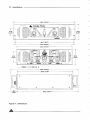
4a2-5 l19.OO"l
_T
Austrdian Monitor
-r-
o
133.O
5?.15
2-26"1
E
l
15.2i1"1
I
461.1 118.16"1
13?.O 117.20"1
f-
"J:( I
li" "ri!!!ll'
9ll
')ll
L:"i l; ll _-w._ :.:ll:.1
920
.i l1: l:
3.A2"1
I
l
- 1/4"
/tu
4
i:"
l
t:g:
r:F:
!@t !:l-L9l o^r
l/a^\,
1T
.ffi
(-)
I
Figure
l")< I
l9l
111.', =l:lr 'll
^;-'fl.tr
'*Dr
Dimensions
BSW (by 4)
lYll
I
t33,O
15.24"t
I
l
.I
Installation
3. Installation
WARNING
Your amplifier must be eanhed at all times!
When you first receive youramplilier il may not have
an
appropriate plug is used and coresponds with the
amplifier's current (ampere) requirements and meets
the approval of your local energy authority.
Please refer termination of this lead to qualified
personnel. Australian Monitor takes no
responsibility for any damage or ha]m resulting
from improper termination of this leadl
Thewires inthe mains lead are coloured in accordance
with the following code:
GREEN AND YELLOW = EARTH
Connect to the terminal marked with the letter E, with
lhe EARTH SYMBOL orcoloured cREEN.
BLUE = NEUTRAL
Connect to the terminal marked with the letler N (or
coloured WHITE in USA and Canada, or coloured
BLACK in the United Kingdom).
BROWN = ACTIVE (LIVE)
Connect to the terminal marked wilh the letterA or L
(or coloured BLACK in USA and Canada or coloured
RED in the United Kingdom).
Power Requirements
Mains Vollage
100 to 120 volts
Circuit Breaker Rating
idle
Power Consumplion at
Consumption at rated 4 ohm
=
power =
Your amplifier is designed for standard 19" reck
mounting and occupies 3 EIA rack units (5.25"). The
mounting centres are:
Vertical: 2.25"
8.1
These units offer two speed fans which run at half
speed, s/vitching tofull speedwhenthe intemal heatsink
temperalure exceeds 600C (1280 F).
An unrestricted airflowinto and outfromthe unit must
be provided. Any restriction ofthe air flow will cause
heat to build up within the unit and possibly force the
unit into its thermal shutdown mode.
lf the unils are lo be operated in an environment
wherethe airflow is restricted such as sealed racks or
even when running 2 ohm loads, the cooling should
be supplemented by extra cooling fans to evacuate
the heated air and aid the flow of cool airthrough the
unit.
Input Wiring
IMPORTANTI Do not directly connec{ pin 1 on the
amplifiefs input or strapping XLR, to the amplifier's
chassis, speaker ground or power ground!
NOTE: lnput signal ground is not to be used as
a safety ground (earth).
The inputto your amplifi er is a balanced 3-pin system
and requires allthree pinsto be connected. Only high
going to the input ofyour amplifiershould bewired as
follows:
Pin
Pin
Pin
Mounting
1
Each channel of your Al.l30OZ amplifier is cooled by
two axialfanswhich drawcoolairfrom the front ofthe
unit and expelthe heated airfrom the rear of the unit.
When wiring for a balanced source the connector
500 Watts
3700 Watts
Ensure thatyour mainsvoltage isthesame aslhe rear
panel mains voltage marker (+/- 10olo).
Horizontal:
Cooling
quality twin-core shielded cable should be used.
40 Amps
20 Amps
220 to 240 volts
(57.15mm)
Australian Monitor
1
=
HOT (ln Phase- non inverting).
GOLD(Reverse Phase- inverting).
GROUND/SHIELD.
ensure that pin 3 is connected to pin 1 (input ground),
either by linking the pins in the input connector or by
the source equipment's output wiring.
When wiring for an unbalanced source:
Pin
The slots in the mounting flange will accept bolt
2=
3=
When wiring from an unbalanced source you must
5" (461. 1 mm) to 1 8.62" (473.0mm).
diameters upto 1/4" (6.35mm).
l
We recommend that you provide additionalsupportfor
the amplifier, especially if road use is planned, asthe
weight can bend some racks otheMise. This support
can be provided by secure shelving, support rails or a
rear rack mounting strip to match upwiththe rear rack
mount points provided on youramplifier.
Mains Lead Wiring
a mains plug attached. You must ensure that
I
2=
Pin3
Pin 1
=
=
HOT (in phasewith the amplifier's output),
GROUNDiSHIELD (ioinsto pin 1).
GROUND/SHIELD
/tu
-t
I2
Installation
NOTE: ln-lineXLR con nectors ofien have alermination
lug that connecisdirec{lyto the chassis of the connector.
Do not link this lug to pin 1 at the amplifier's input as
it will defeat the amplifier's input grounding scheme.
This lug is oflen referred to as a "drain' and is used to
provide a termination to the chassis for shielding
purposes when a floating signal ground is required
When using the NEUTRIK SPEAKoN (NL4MP)
connector for speaker output, use only the mating
NEUTRIK NL4FC in-line connector. This connector is
designed so that both channels can be fed from a
single connector.
Two SPEAKON connec{orsare proMded onthe amdifier.
between the source and destination, or when
disconnecting the signalground is required to reduce
earth loop noise, ornoise induced into signalgrounds
from stray magneticfields.
The "Channel A" SPEAKON actually carries both
OutputWiring
output only.
When wiring to yourspeakers always use the largest
gauge wire yourconnectorwill accept. The longerthe
speaker lead the grealerlhe losseswillbe, resulting in
Thisanangement allowsyou the option of connecting
to the outputs separately or together. Connecting
through a single connector has the advantage of
reduced power and less damping at the load. We
minimising connections, preserving phasing and
simplified channel allocation, which is particularly
important when bi-amping or in bridge mode.
recommend using a heavy duty two co re flex (fou r core
flex if bi-amping) 10 to 12 gauge (2mm'?to2.5mm2or
50/0.25 orequivalent) as a minimum.
channelA & channelB outputs (see Figure 5: Speakon
ConnectorVMring Diagrams).
The "Channel B' SPEAKON canies the Channel B
IMPORTANT
Binding Post Outputs
When terminating to the 4 mm binding post (banana
Do not overload your amplifier by connecting the
channel B oulput twice!
jack) output connectors, banana plugs or bare wires
can be used. The red terminalis positive andthe black
terminal is negative (ground).
ChannelA is used asthe "dominant" channeland when
sourcing a dual output from Channel A the following
standard should be used:
lf running in BRIDGE mode, only lhe red binding
posts are used. channel A provides the positive
output to the load and channel B provides the
ChannelA = Left orLow Frequencies.
channel B = Right or High Frequencies.
negative output to the load.
When in bridge mode:
Pin 1+ = Bridge output Positive.
Pin 2+ = Bridge Output Negative.
SPEAKON Outputs
SINGLE CONNECTION
BRIDGED CONNECTION
DUAL CONNECTION
BI-AMP CONNECTION
Figure 5. "Speakon" ConnectorWiing Diagram
/tu
'
Operation 13
4. Operation
IMPORTANT
All signal source equipment should be adequately
earthed. This not only ensures your safety but
everybody else's as well. Faults can and do occur in
mains connected equipment where the chassis can
become "live" if it is not properly earthed. ln these
inslancesthe fault in a "floating'(un-grounded) piece of
equipment will look for the shortest path to ground
which could possibly be your amplifiefs input. lf the
fault current is large enough it will deslroythe input to
your amplifier and look for the next available path,
which may be you!
Before making any connections to your amplifier
amplifier down when turning the unit on.
When you power up your amplifier, your amplifier
goesthrough an establishment period before itwill
acceptsignal. The lnrush Cunent Suppression (lCS)
circuit is in operation for the first 0.5 seconds. This
limitsthe mains cunent to prevent "nuisance tripping"
ofcircuit breakers.
Ouring this period the THERMAL LED will flash red
whilst the mains voltage gradually charges up the
power supply. You will then hear dual relays "click",
indicating mains is nov!, d ireclly applied tothe amplifier.
While the ICS circuit operates there is also a 30dB
mute on the signalinput. Aftertwo secondsthis mute
will release, allowing any applied sjgnal to pass
unattenuated.
obserVethe following:
1. Ensurethe mains voltage supply matchesthe label
on the rear panel of your amplifier (+/. 10olo).
When s,witching the amplifier off, wait a couple of
seconds before switchinglhe uniton again. Thisallows
the ICS circuit to reset.
2. Ensure that the power switch is OFF (UP)
3.
Ensure that all system grounds (earths) are
connected from a common point. Avoid powering
equipment within a system from multiple power
sources that may be separated by large distances.
4. Checkthe continuity of all inlerconnecting leadsto
your amplifier, ensure that there are no open or
short circuited conduclors.
5. Ensure lhal the power handling of your load
(speakers) can adequately cope with the power
oulput of the amplifier.
Very lmportant
Dueto the high powerabilily ofthe AM3OOZ you need
lo be aware that certein precautions
need
to
be
followed to ensure longevity of youramplifier:
The normaloperating position forthe attenuator is
the "0 dB" position (fully clockwise, no attenuation).
ln this position the amplifier operates at full gain.
Turning the attenuator back (anticlockwise) reduces
the input sensitivity by the amount marked on the
attenuator scale (dial).
NOTE: lf full power output is required you should
operate your amplifierwith the front panel attenualor
above the -1 5dB position, otherwise clipping ofthe
input circuitry end its resultant distorlion will occur
before full output power is achieved.
Sensitivity
- Nevertum youramplifi eron unless all connections
(inputs and speakers) havebeen made!
- Neverplug in a signal lead afferthe amplifierhas
been turned on ! Tum the unit offfirst.
- Never drive the output into clipping if the load
Level Matching
is
Youramplilieris a lineardevice operatingwith a fixed
input to output voltage gain (less aitenuation). The
maximum output voltage swing isdetermined by the
applied mains voltage, load, load type and the duty
cycle ofthe applied signal.
The voltage gain factor of youramplifieris:
53.5times
open circuit or there is no speaker load connected!
or 36d8.
PoweringUp
The input sensitivity for your amplifier when the
attenuator is at the "0" dB attenuation position (fully
clockwise) is nominally:
REMEMBER
The amplifi ershould bethe lastpieceof equipmentthat
you tum on and the @! piece of equipment that you
+3.3dBu
turn off.
+2.2dBu (1.00 volt in) for rated powerintoa
We recommend turning the altenuators on your
load-
Australian Monitor
(1.1
4volts in) forrated powerinto a 8 ohm
load.
4 ohm
/tu
l4
Operation
Each channel of your amplifier has a nominal
balanced input impedance of 2SkOhms (@1kHz)
and should not present a difficult load forany signal
source.
Yoursignal source (i.e. the equipment feeding the
amplifier) should have an output impedance of
600 Ohms orlowerto avoid unwanted high frequency
loss in the cabling.
produces a voltage drop due to thewire's resistance.
This voltage difference between the amp earth and
source equipment earth appears to the amplifier's
input as a signal and is amplified as hum.
There arethree things you can do to avoid earth loop
problems:
1
.
lnput overload occurs at +20.5d8u (8.25 volts).
See lhe specification section for more detailed
information.
Hum Problems
Most equipment is designed forminimum hum when
used under ideal conditions. When connecled to
other equipment, and to safety earth in an electrically
noisy environment however, problems will often
occur.
Thethree "E"sof hum and hum related noisewhich
can plague your audio syslem are:
a) Electrostatic radiation,
b) Electromagnelic radiation, and
c) Earth loops.
Electrostatic radiation capacitively couples to
system elements causing an interference vollage
lhat mainly affects higher impedance paths, such
as amplifierinputs. The sou rce is generally a nearby
high voltage such as a mains lead ora speaker lead.
The problem can usually be reduced by movingthe
offending lead away, or by providing additional
eleclroslatic shielding (i.e. an earthed conductor
which forms a barriertothe field).
Electromagnetic radiation induces interference
currents into system elements that mainly effect
lower impedance paths. Radio transmitters orstray
magnetic fields from mains transformers are often
the cause of this problem. lt is generally more
difficult to eliminate this kind of interference, but
again, moving lhe source away or providing a
magnetic shield (i.e. a steel shield) should help.
Ensure your mains powerforthe audio system is
"quiet" i.e. without equipment on it such as airconditioning, refrigeration or lighting which may
generate noise in the earth circuit.
2.
Ensure all equipment within the system shares
a common ground/ safety earth point. This will
reduce the possibility ofcirculating earth cunents
as the equipment will be referenced to the same
ground potential.
3. Ensure that balanced signal leads going to the
amplifier are connected to earth at one end only.
Signal Ground Lifting
When propersystem hook-up has been carried oul,
you may still have some hum or hum related noise.
Thismaybeduetoanyofthe previouslymentioned
gremlins.
One ofthe most effective waysto reduce earth loop
or eleclromagnetically induced hum isto disconnect
input signal ground at the input connector of your
amplifier. This effeclively breaksthe earth loop path
or open circuits the inpul ground path so
NOTE: lf the input signal ground is lifted you must
ensure adequate shielding ofthe input wiring. lfthe
signal source equipment does not provide adequate
shielding (i.e. a definitive connection to ground) you
must disconnectthe shield from lhe input
connectois
ground pin (Pin-l) and reconnect it to the "drain"
coniact on the inpul connector. This will ensure the
shield on your input wiring actually goes to the
amplifier chassis and subsequently to earth.
DO NOT CONNECT PIN-1 DIRECTLYTO THE
DRAINCONNECTION.
Earth loops can arise from the interfacing of the
various pieces of equipment and their connections
to safety earth.
no
electromagnetically induced currenls can flow
through the amplifier.
You will defeat the amplifiers internal grounding
scheme and possibly cause instability within the
amplifier.
This is by farthe most common cause of hum, and
it occurs when source equipment and the amplifier
are plugged into different poinls along the safety
earth where the safety earth wiring has a current
flowing in it. The current flowing through the wire
/tu
This should only be done when the amplifier is
operated from a balanced signal source.
NOTE: Be wary of quasi-balanced outputs, these
are often no morethan floating unbalanced outputs.
Bridge Mode 15
2.
5. Bridge Mode
The term BRIDGE is used when two independent
amplifier channels are used to drive the same load.
The load is in series (a bridge) between the two
amplifier channels.
Channel A is used as the "dominanl" channel and its
output is in phase with the inpul signal, and channel
B has to have its phase reversed so it is exactly 1800
out of phase with the input signal.
Loop from Channel-A male XLR to Channel-B female inputXLRwith a Reverse Phase Lead.
A reverse Phase Lead is wired:
qlannel-A
Pin-1 to
Pin-2 to
Pin-3 to
qlannel-B
Pin-l
Hn-3
Pin-2
3. Connect your load between the red binding post
output terminals, where the positive side of the
load is connected tothe Channel-A output andthe
As two amplifiers with a phase difference of 1800 are
negative side of the load goes to the Channel-B
now driving the load you will now have double the
vollage into lhe load. This means you will now have
four times the power into that load. The output can
now be considered as an active balanced output.
output . There are no furtherconnections requ ired.
4.
Acommon use of anamplifierin BRIDGE mode is for
driving 70 volt & 100 voltdistribuion lines. ln BRIDGE
mode, The AM3o02 can produce in excess of140 volls
You can also source the output from the channel-A
SPEAKON output connector where Channel-A will
be onthe pin marked 1+ and ChanneFB will be on the
pin marked 2+.
into line impedances greater than 8 ohms.
Equally the units can be used in bridge mode to
provide the correct voltage/power requirements for
an applicable load.
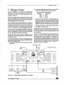
Asshown in Figure 6, there arefoursteps in setting up
yourAttlOO2 amplifierfor running itin BRIDGE mode.
Whilst the amplifier is off,
1. connedthe signal sourcelothe Channel-Afemale
inputXLR.
Tum the ettenuators on both channels fully clockwise (0dB - no attenuetion).
NOTE: You should check aftermarket manufactured
Speakon interconnecting speaker leads before
connecting them to your amplifier. Some leads are
manufactured for specific purposes, or specific use,
and may have pinsshorted insidethe connector. Any
speakon lead with shorted pins will obviously short
the output of your amplifier (either to ground, or
oulput lo output - be careful).
NEVEFgE PRASt LEAO
".^.,
E tr
|@Jm
o
trtr;
ffi
[9J
,a"
h:Al,{
Figure
6
Bridge Mode Speaker Connection
Australian Monitor
/tu
16
Two Ohm or Not Two Ohm
6. Two Ohm or
Not Two Ohm
NOTE: Ensure adequate ventilalion and monitorthe
FAULT indicatorsto guard againstlhermal shutdown
when driving two ohm loads.
excursion into a resistive loadfora sinewave ata given
frequency. Though this method is in line with the
variousslandardsthat exist,
it
only gives an indication
tothe maximum voltage s,wing (before clipping) for a
given load. This method ofrating powerdoes notgive
an indication ofthe
curenl (Ampere) capability ofthe
amplifier, nor does it show the amplifier's ability to
sustain high energywaveforms.
A prcamble.
YourAM3oOZ amplifi erhas been specifi cally designed
to be able to deliver more than twice the curentlhan
The load that a loudspeakerpresentsto an amplifieris
very complex and at different frequencies can be
inductive, cepacitive, resistive, or a combination of
these (reactive). Wth the complex interaction of these
aft ributes, which alterf rom loudspeakerto loudspeaker,
a definitive load for an amplifierdoes nol really exist.
that shown on the specification sheet to cope with
Loudspeekers operating within an enclosure are
specified wilh a nominal impedance. This nominal
impedance isonlya rough guidetothe load it presents
to an amplifier.
As an examde, a loudspeakerwith a nominal impedance
of say 8 ohms, may have an impedance of over 50
ohms at resonance (bass frequencies), drop to less
than 6 ohms aflerthe resonance peak (through ils mid
band area) andthen increase to over l6ohmsforhigher
frequencies.
A 4 ohm load makes an amplifi
erwort"hardei'than an
Sohm load atthe same voltage, as double the curent
is required.
Though various loudspeakers may be marked with the
same nominal impedance, some loads are more difficult
than others.
Bass frequencies usually exhibit higher impedances
and require higher vollages to achieve the desired
result. They also reflect higher energy back to the
amplifiersimply due to the amount of cone excursion
involved at lowerf requencies.
The Mid frequency band usually offers the lowest
impedances and the highestdutycycles requiring both
high voltage and high current.
The High frequency region usually offers a moderale
impedance and usually does not need much voltage
but lhe instantaneous current demand can be much
greaterthan you lhink.
As well as this burden on the amplifier, the transient
waveformsfound in actualusecan demand a lot more
current than the "steady-state" sinewaves used in
most amplifier bench tests.
The poweroutput of yourAM30O2 amplifierquoted on
the specification sheet is derived from a voltage
/tu
difficult loads and/or high energy waveforms.
Thisextra cunent reserve isthe result ofoverengineering
and isthe headroomthe amplifierutilizesto control the
loudspeaker and deal with the "reactive energy" from
the loudspeakerload that has to be dissipated within
theamplifier.
Your AM3o02 amplifier is able to drive 2 ohm loads or
operate in BRIDGE mode into 4 ohms. The operator
mustbe awa re that wh en driving 2 ohm loads orbridged
4 ohm loads that the cunents running in the output
stage are very large and will cause greater heat build
up within the amplifierthan higherimpedance loads.
The Front Panel FAULT lndicators can be used to
provide an indication ofthe "difficulty" ofthe load and
willgivelhe operator an indication ofthe heat build up
in the output stage.
lfthe fault indicatorsflashwith the "clip" LEDSordo not
illuminate untilwell into clipping then lhe load can be
considered as normal or easy.
lf the fault indicator slarts to flash before the "clip"
LEDS then the load should be considered complex
and/ordifficult.
For the more complex and/or difficult loads, the
illuminalion of the "fault" LED on programme peaks
should be inlerpreted asthe output levellimit. Driving
the output conlinuously past this point could result in
muting of the output stage, breakers tripping or
prematu
re
thermal
sh
utdown.
The fault detection circuit is also lhermally
compensated, and fault indication will occurearlier
when the unit is hot. lf the "fault" LED continually
lights earlier than normal, then the unit is healing
up. lfthe signal level is not reduced lo compensate
for the heating of the unit then thermal shutdown
may occur.
Maintenance 17
T.Maintenance
Your AM3002 amplifier will need minimal
maintenance. No internal adjustments need to be
made to lhe unit to maintain optimum performance.
To provide years ofunhindered operation we suggest
a maintenance inspection be carried out on a regular
basis, say every 12 months or so.
Fans
Due to the openness of the air path through your
AM3O02 amplifier, very little dust should settle
within the amplifier. The unit has been designed so
that any dust and/or foreig n particles that do settle
within the amplifierwill not unduly hinderthe cooling
Overtime, dust may build up on the leading edgeof
the fan blades and reduce their cooling efficiency.
Thelime taken forthis to happen willdepend on the
environment and the amount of use.
The fan blades are accessible once the lids are
removed and can be easily cleaned. You need only
hold the fan rotor still and wipe the dust off the
blades. Many users stall the fan and use
compressed airto blow the dust off the fan blades.
It is important to note that the fan blades must be
held stillwhilst blowing airoverthe blades otherwise
you may burn out the bearings in the fan.
NOTE:
ofthe unit.
Make sure the unit is off and is unplugged from the
The mesh grille in front of the fanswill actto limitthe
amount of dusl and lint entering the unit. You will
find in time that there will be a build up of dust and
discharge before removing lids.
lintontheg llewhich maystartto hindertheairflow
Only competent or qualified persons should
through the unit. You should periodically removelhe
dust and keep the grille clean.
attempt any service or mainlenance of youramplifier!
Australian Monitor
mains. Give the main filter capacitors time to
/tu
18 Warranty
8. Warranty
of
take reasonable care in use and maintenance of the
Australian Monitorwanants the originalpurchaser
amplifier.
(purchased
authorised
at
an
emplifier
each AM3OO2
Australian Monitor dealer) that it will be free from
To validate thiswananty, the original purchaser must
defects in materials and wortmanship for a period
complete and mail the wananty registration card
years
ofpurchase.
(2)
originaldate
from
the
two
directly to Australian Monitor within fourteen (14)
Australian Monitorwill, at its option, repair or replace days of purchase.
any unit or component covered by this wananty
whlch becomes defeclive or malfunctions under To obtain wananty service, the equipmentshould be
shippedto an authorised Australian Monitordealeror
normal use and service during the period of
parts
to
direct to Australian Monitor. Freight to Australian
or
labour
charge
for
warranty, at no
Monitor is at the owne/s expense.
original
of
this
the
owner.
This warranty does not coverthemal problems
dueto obstructed airflow, or defects ormalfunctions resulting from accidents, misuse, abuse,
operation with the incorrect AC mains voltage,
connection to faulty equipment, modification or
alteration withorJt priorfactoryapprovalorservice
by unauthorised personnel.
Unitswith
a
defaced serialnumberwillnot be accepted
for wananty service. Any evidence of alteration,
erasure or forgery of the purchase receipt will also
void this warranty'
Australian Monitor accepts no liability for any
consequential damages, whether direct or
indirect, arising from the use or misuse of its
products'
normal
ensure
that
It is the owner's responsibility to
maintenance inspections are carried out at regular
intervalsas rccommended inthe maintenance section Australian Monitor reserves the right to alter its
of this manual. Australian Monitor reserves the righl designs and specifications at any time without nolice
or obligation to previous purchasers.
to refuse wananly service where the owner fails
to
/fu
Australian Monitor
AM -sentes
z YEAR
wARRANw
REG
lsrRATloN
IMPORTANT
Please complete this card and return it immediately after unpacking the product'
This card is to be sent DIRECTLY to Australian Monitor'
NOTE! Warranty is effective ONLY upon receipt of this card.
COMPANY
NAME
MODEL
ADDRESS
SERIAL N"
DATE PURCHASED
DEALER
CITY
CODE
STATE
COUNTRY
Ensure that you fi| out and send your wananty rcgistration card.
use this copy to rccord a duplicate of the details.
/tu
-
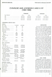
Specification
l9
EIA Output Power @ ltJlz}.loh / 1.0%THD+N(inwatts)
8ohm
4
ohm
ohm
2
Single Channel
680
I
720
1,200
I
1,290
l,t6o l2,ol0
Both Channels
630
I
67s
1,080
/
1,150
1,600
6'70
Rating(AVG)
Output Power 20Hz to
2,kllz
@ 1% THD
1,800
1,180
2,12s I 2,2s0
Brideed
3,200
I r,730
I 3,460
+N (inwatts)
ohm
4
Single Channel
675
1,100
1,750*
Both Channels
650
1,000
1,600{'
Bridged
2,175
3,250*
8
ohm
2
+
ohm
Limit
= I 5kllz Sweep
Tone Burst IHF - 202 (20 cycles @ Clip, 480 Cycles @ -20dB re lkHz)
E
ohm
4
ohm
2
ohm
Single Charnel
1,320
2,200
Both Channels
1,230
2,000
Distortion
THD+N
IMDSMPTE
IMD DIM 30
(0.5 dB below clipping re 4 ohms)
<0.0170
(@ 1 kHz)
<0.02o/o
(60 Hz & 7 kHz 4:1)
(3.15kH2 square & 15 kHz) <0.030/0
Output Impedance @ 1 kHz
Damping Factor @ 1 kHz
re
I
1.0
Voltage Gain
vrms (+2.2 dBu)
63.5 times (36 dB)
@ 1 kHz (re 8 ohm rating)
<3.0pS
Signal / Noise ratio
"A" weighted (re I ohm rating)
(leading edge,20kHz square wave @ clipping)
Input Impedance
1.14 Vrms (+3.3 dBu)
>400:1
>50V per pS
Frequency Response
20 Hz - 20 k{z
(nominally)
For raled power re 8 ohm
For rated power re 4 ohm
Input CMRR
ohms
(80%, leading edge of20kHz square wave)
Slew Rate
Input Sensitivity
<o.o2o ohms
Output Rise Time
-3dB points
>4,000
>2,450
Bridged
< * 0.25 dB
<10 Hz - 80 kHz
>106 dB
rating)
>9odB
Crosstalk @I
kHz (re 8 ohm
Weight ruetzo.s
lb (32ks), Shippins 77.olb (3s.sks)
Dimensions H xw xD
excluding
including
Lineto Line (Balanced)30k
>90 dB
handles
handles
133
133
x tl83 x 445
x 1183 x 530
(mm)
(mm)
(19 inch EIA rack mounling, 3 units high)
Test conditions
ground
referenced (0MRR test had floating gound & 50 ohm
lnput source = 600 ohm, Batanced and
source). Mains regutated to 240 vofts / ,Ohz. All measurements taken at binding posl output terminals.
Standard production units measured. No comrynsation applied.
Australian Mon'rtor
-l
Australian Monitor
www. au stra ian mon itor. com. au
I
Distributed by:
Audio Telex Communications Pty Ltd
ACN001345482
www. audiotelex. com. au
lnternational Enquiries
Ph: 612 9647 1 41 1,
F
ax 612 97 48 2537, E-mail: [email protected]
Sydney
Ph: (02) 9647 I 41 1, F ax: (02) 9648 3698, E-mail: [email protected]. au
Melbourne
Ph: (03) 9890 7477,Fax: (03) 9890 7977, E-mail: [email protected]
Brisbane
Ph: (07) 3852 131 2,
F ax: (O7 )
3252 1237, E-mail: [email protected]
Adelaide
Ph: (08) 8352 4444,Fax: (08) 8352 4488, E-mail: [email protected]
Perth
Ph: (08) 9228 4222,
F
ax
(OA)
9228 4233, E-mail: [email protected]
Auckland
Ph: (09)4159426, Fax (09)4'15 9864, E-mail: [email protected]
trrtl-trr:1
I Lli l*,I Lli
L:!
L:jl
'ffi
Y$:i*.si"
I