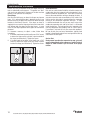
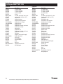
1
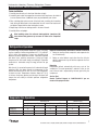
SCIENTIFIC
Undercounter Laboratory/Pharmacy Refrigerators/Freezers
Installation, Use And Care Manual
Please read this manual completely before attempting to install or operate this equipment! Notify carrier of damage!
Inspect all components immediately.
LU406CA
CAUTION
Important Information
Read Before Use
Please Save These Instructions!
February 2014
*9294526*
Delfield Scientific
Important Warning And Safety Information
WARNING
Read This Manual Thoroughly Before Operating, Installing, Or Performing Maintenance On The Equipment.
WARNING
Failure To Follow Instructions In This Manual Can Cause Property Damage, Injury Or Death.
WARNING
Do Not Store Or Use Gasoline Or Other Flammable Vapors Or Liquids In The Vicinity Of This Or Any Other
Appliance.
WARNING
Unless All Cover And Access Panels Are In Place And Properly Secured, Do Not Operate This Equipment.
WARNING
This Appliance Is Not Intended For Use By Persons Who Lack Experience Or Knowledge, Unless They Have
Been Given Supervision Or Instruction Concerning Use Of The Appliance By A Person Responsible For Their
Safety.
WARNING
This Appliance Is Not To Be Played With.
Warning
Do Not Clean With Water Jet.
WARNING
Do Not Use Electrical Appliances Inside The Food Storage Compartment Of This Appliance.
CAUTION
Observe the following:
2
•
Minimum clearances must be maintained from all walls and combustible materials.
•
Keep the equipment area free and clear of combustible material.
•
Allow adequate clearance for air openings.
•
Operate equipment only on the type of electricity indicated on the specification plate.
•
Unplug the unit before making any repairs.
•
Retain this manual for future reference.
For customer service, call (800) 733-8829, (800) 773-8821, Fax (989) 773-3210, www.delfield.com
SCIENTIFIC
Undercounter Laboratory / Pharmacy Refrigerators / Freezers
Contents
Receiving & Inspecting Equipment.................................................. 3
Serial Number Location................................................................... 4
Warranty Information....................................................................... 4
Regulatory Certifications.................................................................. 4
Specifications................................................................................... 5
Installation....................................................................................... 6
Caster Installation............................................................................ 7
Refrigeration Operation.................................................................... 7
Evaporator Fan Operation................................................................ 7
Freezer Operation............................................................................. 8
Maintenance................................................................................9-10
Wiring Diagrams............................................................................ 11
Replacement Parts Lists...........................................................12-13
Standard Labor Guidelines............................................................. 14
Notes............................................................................................. 15
Receiving & Inspecting The Equipment
Even though most equipment is shipped crated, care should be
taken during unloading so the equipment is not damaged while
being moved into the building.
1. Visually inspect the exterior of the package and skid or
container. Any damage should be noted and reported to
the delivering carrier immediately.
5. Be certain to check the compressor compartment housing
and visually inspect the refrigeration package. Be sure
lines are secure and base is still intact.
6. Freight carriers can supply the necessary damage forms
upon request.
7. Retain all crating material until an inspection has been
made or waived.
2. If damaged, open and inspect the contents with the carrier.
3. In the event that the exterior is not damaged, yet upon
opening, there is concealed damage to the equipment
notify the carrier. Notification should be made verbally as
well as in written form.
4. Request an inspection by the shipping company of the
damaged equipment. This should be done within 10 days
from receipt of the equipment.
SCIENTIFIC
For customer service, call (800) 733-8829, (800) 773-8821, Fax (989) 773-3210, www.delfield.com
3
Delfield Scientific
Serial Number Location
The serial number on LU406(CA) & LU407(CA) compact
refrigerators and freezers is printed on the right side of the
interior back wall.
LU4427N(-G) serial tags are located either on the left upper
sidewall inside the cabinet or under the top nosing directly above
the door when the door is in the closed position.
Always have the serial number of your unit available when calling
for parts or service. For parts and services contact Delfield at
(800) 733-8829.
©2014 The Delfield Company. All rights reserved. Reproduction without written
permission is prohibited. “Delfield” is a registered trademark of The Delfield Company.
Warranty Information
Visit http://www.delfieldscientific.com/?xhtml=xhtml/mcl/us/en/general/warranty-info.html to:
• Register your product for warranty.
• Verify warranty information.
• View and download a copy of your warranty.
Regulatory Certifications
Models are certified by:
Underwriters Laboratories (UL)
Underwriters Laboratories of Canada (ULC)
4
For customer service, call (800) 733-8829, (800) 773-8821, Fax (989) 773-3210, www.delfield.com
SCIENTIFIC
Undercounter Laboratory / Pharmacy Refrigerators / Freezers
Specifications
Undercounter Refrigerator & Freezer With Subtop And 3.75” Casters
Model
Description
L
D
H
Volume Ft.3
Shelves Ft.2
H.P.
Refg. Charge
Amp
LU406CA
refrigerator
27.00”
(69cm)
27.75”
(70cm)
33.25”
(84cm)
5.7
4.6
1/5
7.0 oz
4.0
5-15P
168lbs
(76kg)
LU407CA
freezer
27.00”
(69cm)
27.75”
(70cm)
33.25”
(84cm)
5.7
4.6
1/5
7.0 oz
5.8
5-15P
168lbs
(76kg)
NEMA Plug Ship Weight
Undercounter Refrigerator & Freezer Bases With Stainless Steel Top
Model
Description
L
D
H
Volume Ft.3
Shelves Ft.2
H.P.
Refg. Charge
Amp
NEMA Plug
Ship Weight
LU406
refrigerator
27.00”
(69cm)
28.50”
(72cm)
33.25”
(84cm)
5.7
4.6
1/5
7.0 oz
4.0
5-15P
176lbs
(80kg)
LU407
freezer
27.00”
(69cm)
28.50”
(72cm)
33.25”
(84cm)
5.7
4.6
1/5
7.0 oz
5.8
5-15P
176lbs
(80kg)
Flat Top & Work Top Refrigerator Bases
Model
Description
L4427N-G
L4427N
Volume
FT3
Shelves FT2
H.P.
Refg. Charge
Amp
NEMA Plug
Ship Weight
36.00”
(91cm)
8.20
3.17
1/5
7.0 oz
3.9
5-15P
223lbs
(101kg)
36.00”
(9cm)
8.20
3.17
1/5
7.0 oz
3.9
5-15P
223lbs
(101kg)
L
D
Work H
one glass door
27.00”
(69cm)
31.50”
(80cm)
one S/S door
27.00”
(69cm)
31.50”
(80cm)
SCIENTIFIC
For customer service, call (800) 733-8829, (800) 773-8821, Fax (989) 773-3210, www.delfield.com
5
Delfield Scientific
Installation
Location
Units represented in this manual are intended for indoor use
only. Be sure the location chosen has a floor strong enough to
support the total weight of the cabinet and contents. Reinforce the
floor as necessary to provide for maximum loading.
For the most efficient refrigeration, be sure to provide good air
circulation inside and out.
Inside cabinet: Do not pack refrigerator so full that air cannot
circulate.
Outside LU cabinets: Be sure that the unit has access to ample air.
On all undercounter equipment, a minimum space of 3” (7.6cm)
at the back of the unit and 1” (2.5cm) at the top and sides is
required to conform to Underwriters Laboratories’ standards.
On undercounter units it is imperative that the proper air flow be
maintained. The refrigeration system is designed so air will flow
under the unit, over the compressor/condenser area, and out
at the top rear of the unit. Avoid hot corners and locations near
stoves and ovens.
Outside L cabinet: These cabinets have a front-breathing design.
They may be installed flush against a wall or built into a counter
as required.
The louver at the floor level must be kept completely clear of any
obstructions. Proper operation of these models is dependent on
air being able to flow freely through the front louver. The louver at
the back of the cabinet is not necessary for proper operation, but
any air flow through it is beneficial.
Any restriction of the proper air flow outlined
above, total or partial, will void the warranty on
the unit.
Electrical connection
Refer to the amperage data in the specifications table, the serial
tag, your local code or the National Electrical Code to be sure the
unit is connected to the proper power source. A protected circuit
of the correct voltage and amperage must be run for connection
of the line cord, or permanent connection to the unit.
A 6’ (1.8 m) long grounded supply cord and three-pronged plug
are provided with standard units. Simply plug into a three-pronged
wall outlet to begin operation. Do not use an adapter to connect to
a two-pronged outlet. The three-pronged outlet provides a ground
connection which must be used to prevent a shock hazard.
The wall outlet must be checked by a qualified
electrician to be sure a proper ground is present
and that the outlet provides the correct voltage and
required amperage to match the rating plate.
Any power cord that is frayed or damaged should be
replaced. When disconnecting the cabinet from the
power source, do not pull on the cord. Firmly grip the
plug and remove from outlet.
The thermostat must be turned to OFF and the unit
disconnected from the power source whenever
performing service, maintenance functions or
cleaning the refrigerated area.
Shelf Installation Instructions
1. Notice the shelves have four alignment pins on the
underside and a backstop on the top back.
2. Insert the shelves into the cabinet.
• The backstop should be at the top back.
Leveling
A level cabinet will perform better because the drain pan will drain
properly, the drawers or doors will line up with the frames and the
cabinet will not be subject to undue strain. Ensure the floor where
the unit is to be located is level.
Stabilizing
• The alignment pins should be in front and back of the
shelf supports.
Models are supplied on casters for your convenience, for ease of
cleaning underneath and mobility.
The unit must be installed in a stable condition with
the front wheels locked. Locking the front casters
after installation is the owner’s responsibility.
Plumbing
Self-contained models are standard with a condensate evaporator.
If, for some reason, a unit does not have a condensate evaporator,
or the evaporator fails, the unit’s drain must have an outlet to an
appropriate drainage area or container.
Moisture collecting from improper drainage can
create a slippery surface on the floor and a hazard to
CAUTION employees. It is the owner’s responsibility to provide
a container or outlet for drainage.
6
For customer service, call (800) 733-8829, (800) 773-8821, Fax (989) 773-3210, www.delfield.com
SCIENTIFIC
Undercounter Laboratory / Pharmacy Refrigerators / Freezers
Undercounter Caster Installation
Caster installation
1.Carefully place the unit on its back (see illustration at right).
Plate Casters
W/Locks
2.Located on each end of the compressor channel are 4 hex head screws, for a total of
8 screws. Remove them. 8 additional screws are provided with your casters.
3.Place a locking plate caster over one of the front holes, matching the 4 mounting
holes to the pre-drilled holes in the underside of the unit. Insert 4 hex head screws
and tighten. Repeat with the other locking front casters.
Plate Casters
W/O Locks
Screws
4.Repeat step 4 with the non-locking casters in the rear of the unit.
Plate caster installation, 400 & 4000 Series.
5.Carefully lift the unit upright.
WARNING
After installing casters, the unit must stand upright for twenty-four (24)
hours before being powered up to assure oil return to the compressor
sump.
Refrigeration Operation
Environmentally friendly R404A refrigerant is used. The system
has the capability of maintaining between 33°F (1˚C) and 40°F
(4˚C) in heavy use operations. Systems are controlled using
Delfield’s electronic temperature control. It provides improved
pull down times, reducing compressor cycling and longer
compressor life with lower energy consumption. Evaporator
condensate is eliminated using an energy efficient hot gas
system.
After the unit is connected to power it will automatically begin
operating. With the doors closed, the temperature of the
cabinet should reach 36°F to 40°F (2°C to 4°C) on refrigerators
in about one hour. Temperature maintains about 38°F (3°C)
in the box. Continuous opening and closing of the doors will
hamper the unit’s ability to maintain optimum refrigeration
temperature.
Important Front-Breathing Information, L4427N & L4427N-G
1. During the cooling mode, compressor and evaporator fan
run simultaneously.
2. During an actual defrost event other than the off-cycle
defrost, compressor stays off but the evaporator fan runs
continuously.
Defrosting
Refrigerators defrost automatically with every cycle of the
compressor. The water generated is routed to a pan on the
rear of the unit and is evaporated by the heat given off by the
compressor.
Service Alert
Contact Technical Support at 1-800-733-8829 if you are
unsure of the proper function.
Evaporator Fan Operation
Cooling Cycle
Defrost Cycle
Compressor On
Evap Fan On
LU406(CA)
X
LU407(CA)
X
L4427N(-G)
X
SCIENTIFIC
Compressor Off
Evap Fan Off
Evap Fan On
Compressor Off
Evap Fan Off
X
Evap Fan On
X
X
Evap Fan Off
X
X
X
For customer service, call (800) 733-8829, (800) 773-8821, Fax (989) 773-3210, www.delfield.com
7
Delfield Scientific
Freezer Operation
Environmentally friendly R404A refrigerant is used. The
system has the capability of maintaining between -4°F (-20˚C)
and 0°F (-17˚C) in heavy use operations. System is controlled
using Delfield’s electronic temperature control, which provides
improved pull down times, reducing compressor cycling
and longer compressor life with lower energy consumption.
Control system automatically defrosts the evaporator coil
every 4 hours to assure evaporator coil is free of ice and
operating at optimum efficiency. Evaporator condensate is
eliminated using an energy efficient hot gas system.
completed initializing, the electronic temperature control will
cycle the compressor, evaporator fan motor, and condenser
fan motor to maintain box temperature at the control setting.
With the doors closed, the temperature of the cabinet should
reach 0°F (-18°C) on freezers in about one hour. Continuous
opening and closing of the doors will hamper the unit’s ability
to maintain optimum temperature.
Freezer Manual Defrost
The electronic temperature control constantly monitors box
temperature as well as evaporator coil temperature to maintain
consistent product temperatures. As an added energy-saving
feature, the electronic controller will switch the evaporator
fan motor on and off with the compressor and condenser fan
motor.
Service Alert
During normal operation the evaporator fan may cycle and/
or pulse independently of the compressor. Contact Technical
Support at 1-800-733-8829 if you are unsure of the proper
function.
IMPORTANT NOTE REGARDING FREEZERS:
Whenever the freezer is plugged in, and the control has
Freezer Automatic Defrost
The control also monitors compressor total running time
and will enter a defrost cycle after total compressor running
time is greater than 4-hours since the last defrost cycle OR
if evaporator coil temperature drops below -34°F (indicating
excessive frost on the coil).
When the control enters the defrost mode, whether manual
or automatic, it switches off the evaporator fan motor,
compressor and condenser fan motor, and switches on the
defrost heater to warm the evaporator coil and melt all frost
accumulated during the previous refrigeration cycle. The
control will continue the defrost cycle for a MINIMUM of 8
minutes and a MAXIMUM of 30 minutes depending on the
amount of frost accumulated on the evaporator coil.
After the defrost cycle is complete, the control returns to a
normal refrigeration cycle, however the evaporator fan motor
will not switch on for 2 minutes AFTER the compressor and
condenser fan motor have begun operating.
Electronic Temperature Control Location & Adjustment
The control is located in the control box at the rear of the unit.
It is factory set at mid-range to maintain about -3°F (-18°C)
box temperature.
Danfoss AK-CC210 Control
If at any time the wrong selection is made
stop pressing buttons and wait approximately 30
seconds and the display will time out. Restart
from the first step.
To Adjust Set Point (Desired Temp)
1. Press and release the center button one time and the
display will show the cabinet set point.
2. Use the top and bottom buttons to adjust the temp
higher or lower to the desired temperature. (note: if the
desired temperature is between 38 and 42 degrees set
the temperature set point at 40 as the temp will fluctuate
above and below the set point) .
3. Once the desired set point is reached on the display,
press and release the center button one time to accept
that temperature.
To Change From Celsius to Fahrenheit:
1. Press and hold the top button of the control until the
display shows r01 then release the button.
2. Press the bottom button approximately 4 times until the
display reads r05.
3. Press and release the center button on time and the
display will show ˚F or ˚C
4. To change use the top or bottom button to scroll and
select the temp format required.
5. Once the chosen format is visible in the display press and
release the center button one time.
6. The display will return and say r05.
7. Do not press any buttons at this point, The display will
time out in approximately 30 seconds and display the
chosen format.
The set point regulates air temperature. The display
is a measure of the bottle temperature. Initially there
could be up to 3°F (1.6°C) difference between these
two temperatures. It may take up to two hours for the
bottle temperature (display) to reach the set point.
8
For customer service, call (800) 733-8829, (800) 773-8821, Fax (989) 773-3210, www.delfield.com
SCIENTIFIC
Undercounter Laboratory / Pharmacy Refrigerators / Freezers
Maintenance
The thermostat must be turned to OFF and
the unit disconnected from the power source
whenever performing service, maintenance
functions or cleaning the refrigerated area.
Refrigerators and Freezers
The interior and exterior can be cleaned using soap and warm
water. If this isn’t sufficient, try ammonia and water or a
nonabrasive liquid cleaner. When cleaning the exterior, always
rub with the “grain” of the stainless steel to avoid marring the
finish.
Do not use an abrasive cleaner because it will scratch the
stainless steel and plastic and can damage the breaker strips
and gaskets.
Cleaning the Condenser Coil
The condenser coil requires regular cleaning, recommended
is every 90 days. In some instances though you may find
that there is a large amount of debris and dust or grease
accumulated prior to the 90 day time frame. In these cases the
condenser coil should be cleaned every 30 days.
If the build up on the coil consists of only light dust and debris
the condenser coil can be cleaned with a simple brush, heavier
dust build up may require a vacuum or even compressed air to
blow through the condenser coil.
If heavy grease is present there are de-greasing agents available
for refrigeration use and specifically for the condenser coils.
The condenser coil may require a spray with the de-greasing
agent and then blown through with compressed air.
Failure to maintain a clean condenser coil can initially cause high
temperatures and excessive run times, continuous operation
with dirty or clogged condenser coils can result in compressor
failures. Neglecting the condenser coil cleaning procedures
will void any warranties associated with the compressor or cost
to replace the compressor.
CAUTION
Never use a high pressure water wash for this
cleaning procedure as water can damage the
electrical components located near or at the
condenser coil.
In order to maintain proper refrigeration performance, the
condenser fins must be cleaned of dust, dirt and grease
regularly. It is recommended that this be done at least every
three months. If conditions are such that the condenser is totally
blocked in three months, the frequency of cleaning should be
increased. Clean the condenser with a vacuum cleaner or stiff
brush. If extremely dirty, a commercially available condenser
cleaner may be required.Stainless Steel Care and Cleaning
To prevent discoloration or rust on stainless steel several
important steps need to be taken. First, we need to understand
SCIENTIFIC
the properties of stainless steel. Stainless steel contains 70-80%
iron which will rust. It also contains 12-30% chromium which
forms an invisible passive film over the steels surface which
acts as a shield against corrosion. As long as the protective
layer is intact, the metal is still stainless. If the film is broken
or contaminated, outside elements can begin to breakdown the
steel and begin to form rust of discoloration.
Proper cleaning of stainless steel requires soft cloths or plastic
scouring pads.
NEVER USE STEEL PADS, WIRE BRUSHES OR
SCRAPERS!
CAUTION
Cleaning solutions need to be alkaline based or non-chloride
cleaners. Any cleaner containing chlorides will damage
the protective film of the stainless steel. Chlorides are also
commonly found in hard water, salts, and household and
industrial cleaners. If cleaners containing chlorides are used be
sure to rinse repeatedly and dry thoroughly upon completion.
Routine cleaning of stainless steel can be done with soap and
water. Extreme stains or grease should be cleaned with a nonabrasive cleaner and plastic scrub pad. It is always good to
rub with the grain of the steel. There are also stainless steel
cleaners available which can restore and preserve the finish of
the steels protective layer.
Early signs of stainless steel breakdown can consist of small
pits and cracks. If this has begun, clean thoroughly and start to
apply stainless steel cleaners in attempt to restore the passivity
of the steel.
CAUTION
Never use an acid based cleaning solution!
Many food products have an acidic content which
can deteriorate the finish. Be sure to clean the
stainless steel surfaces of ALL food products.
Common items include, tomatoes, peppers and
other vegetables.
If your freezer seems to vibrate excessively when the
compressor is running, loosen (but do not remove) the
bolts on the compressor. Semi hermetic models should be
loosened before operating.
Gasket Maintenance
Gaskets require regular cleaning to prevent mold and mildew
build up and also to keep the elasticity of the gasket. Gasket
cleaning can be done with the use of warm soapy water. Avoid
full strength cleaning products on gaskets as this can cause
them to become brittle and prevent proper seals. Also, never
use sharp tools or knives to scrape or clean the gasket which
could possibly tear the gasket and rip the bellows.
For customer service, call (800) 733-8829, (800) 773-8821, Fax (989) 773-3210, www.delfield.com
9
Delfield Scientific
Maintenance Continued
Gaskets can easily be replaced and do not require the use of
tools or authorized service persons. The gaskets are “Dart”
style and can be pulled out of the grove in the door and new
gaskets can be “pressed” back into place.
Doors/Hinges
Over time and with heavy use doors the hinges may become
loose. If it is noticed that the door is beginning to sag, it may
become necessary to tighten the screws that mount the hinge
brackets to the frame of the unit. If the doors are loose or
sagging this can cause the hinge to pull out of the frame which
may damage both the doors and the door hinges. In some
cases this can require qualified service agents or maintenance
personnel.
If it becomes necessary to adjust a door, follow these
instructions:
1. If the door needs lowering at the handle, use a 5/16” wrench
to loosen the hinge screws and install a spacer outside of
the hinge (see illustration 1). Tighten the screws.
2. If the door needs to be higher at the handle, use a 5/16”
wrench to loosen the hinge screws and install a spacer
inside of the hinge (see illustration 2). Tighten the screws.
Illustration 1:
spacer outside
10
Drain Maintenance
Each unit has a drain located inside the unit which removes the
condensation from the evaporator coil and evaporates it at an
external condensate evaporator pan. Each drain can become
loose or disconnected from moving or bumping the drain. If
you notice excessive water accumulation on the inside of the
unit be sure the drain tube is connected from the evaporator
housing to the condensate evaporator drain pan. If water
is collected underneath the unit you may want to check the
condensate evaporator drain tube to be sure it is still located
inside the drain pan. The leveling of the unit is important as the
units are designed to drain properly when on a level surface,
if your floor is not level this can also cause drain problems.
Be sure all drain lines are free of obstructions, typically food
product is found blocking drain lines causing water to back up
and overflow the drain pans.
Service Alert
During normal operation the evaporator fan may cycle and/
or pulse independently of the compressor. Contact Technical
Support at 1-800-733-8829 if you are unsure of the proper
function.
Illustration 2:
spacer inside
For customer service, call (800) 733-8829, (800) 773-8821, Fax (989) 773-3210, www.delfield.com
SCIENTIFIC
Undercounter Laboratory / Pharmacy Refrigerators / Freezers
Wiring Diagram Refrigerator, LU406(CA), L4427N(-G )
Wiring Diagram Freezer, LU407(CA)
SCIENTIFIC
For customer service, call (800) 733-8829, (800) 773-8821, Fax (989) 773-3210, www.delfield.com
11
Delfield Scientific
LU Replacement Parts Lists
LU406(CA)
Part #
Description
3234025
3” Caster, brake
3234024
3” Caster, no brake
3234160
5” Caster, no brake
3234161
5” Caster, brake
3234791
6” Leg
000-B3I-0102
27” Door, right hand, locks, solar
0074057
Capillary tube (.044 id x 144”)
3526997Compressor
3516446
Compressor relay
2194787
Compressor start capacitor
158-ATA-0050
Condensate coil, hot gas
149-AWM-0040
Condensate pan
3516275
Condenser coil
3516172
Condenser fan blade, clear lexan
2162691
Condenser fan motor
1702623
Door gasket
3516116
Evaporator coil
3516172
Evaporator fan blade, clear lexan
2162691
Evaporator fan motor
3516321
Filter drier
0420067
Hinge kit (left or right hinged)
000-CEZ-0030
Product Simulator
2194756
Sensor, Air
2194755
Sensor, Defrost
2195128
Sensor, Product
3978271Shelf
3235014
Shelf clip
000-CZ0-0047KT-S Temperature control kit
9294820
Wiring Diagram
12
LU407(CA)
Part #
Description
3234025
3” Caster, brake
3234024
3” Caster, no brake
3234160
5” Caster, no brake
3234161
5” Caster, brake
3234791
6” Leg
000-B3I-0102
27” Door, right hand, locks, solar
0074058
Capillary tube (.036 id x 168”)
3526996Compressor
3516446
Compressor relay
2194787
Compressor start capacitor
158-ATA-0050
Condensate coil, hot gas
149-AWM-0040
Condensate pan
3516275
Condenser coil
3516172
Condenser fan blade, clear lexan
3516173
Condenser fan guard
2162715
Condenser fan motor
2194774
Defrost heater
3516156
Defrost timer
1702623
Door gasket
3516418
Evaporator Coil
3516172
Evaporator fan blade, clear lexan
3516173
Evaporator fan guard
2162691
Evaporator fan motor
3516321
Filter Drier
3978055
Heater guard, 18”
0420067
Hinge kit (left or right hinged)
000-CEZ-0031
Product Simulator
2194756
Sensor, Air
2194755
Sensor, Defrost
2195128
Sensor, Product
3978271Shelf
3235014
Shelf clip
000-CZ0-0048KT-S Temperature control kit
9294819
Wiring Diagram
For customer service, call (800) 733-8829, (800) 773-8821, Fax (989) 773-3210, www.delfield.com
SCIENTIFIC
Undercounter Laboratory / Pharmacy Refrigerators / Freezers
L4427N & L4427N-G Replacement Parts Lists
L4427N
Part #
Description
3234025
3” Caster, brake
3234024
3” Caster, no brake
3234160
5” Caster, no brake
3234161
5” Caster, brake
3234791
6” Leg
000-B4X-0062
27” Door, right hand, locks, solar
0074183
Capillary tube (.036 id x 168”)
3526997Compressor
3516446
Compressor relay
2194787
Compressor start capacitor
158-B6P-0045
Condensate coil, hot gas
149-COM-0030
Condensate pan
3516296
Condenser coil
2162681
Condenser fan blade, clear lexan
3516178
Condenser fan guard
2162667
Condenser fan motor
1702474
Door gasket
3516298
Evaporator Coil
3517356
Evaporator fan blade, clear lexan
2162715
Evaporator fan motor
3516321
Filter Drier
0420067
Hinge kit (left or right hinged)
000-CEZ-0030
Product Simulator
2194756
Sensor, Air
2194755
Sensor, Defrost
2195128
Sensor, Product
3978274Shelf
000-CZ0-0047KT-S Temp. control kit
9294820
Wiring Diagram
SCIENTIFIC
L4427N-G
Part #
Description
3234025
3” Caster, brake
3234024
3” Caster, no brake
3234160
5” Caster, no brake
3234161
5” Caster, brake
3234791
6” Leg
0074183
Capillary tube (.036 id x 168”)
3526997Compressor
3516446
Compressor relay
2194787
Compressor start capacitor
158-B6P-0045
Condensate coil, hot gas
149-COM-0030
Condensate pan
3516296
Condenser coil
2162681
Condenser fan blade, clear lexan
3516178
Condenser fan guard
2162667
Condenser fan motor
3455629
Door, glass
1702814
Door gasket
3516298
Evaporator Coil
3517356
Evaporator fan blade, clear lexan
2162715
Evaporator fan motor
3516321
Filter Drier
3237542
Hinge Bracket, LH Bottom, RH Top, for
glass door
3237543
Hinge Bracket, RH Bottom, LH Top, for
glass door
000-CEZ-0030
Product Simulator
2194756
Sensor, Air
2194755
Sensor, Defrost
2195128
Sensor, Product
3978274Shelf
000-CZ0-0047KT-S Temp. control kit
9294820
Wiring Diagram
For customer service, call (800) 733-8829, (800) 773-8821, Fax (989) 773-3210, www.delfield.com
13
Delfield Scientific
Standard Labor Guidelines To Repair Or Replace Parts On Delfield Equipment
Advice and recommendations given by Delfield Service Technicians do not constitute or guarantee any special coverage.
•A maximum of 1-hour is allowed to diagnose a defective component.
•A maximum of 1-hour is allowed for retrieval of parts not in stock.
•A maximum travel distance of 100 miles round trip and 2-hours will be reimbursed.
•Overtime, installation/start-up, normal control adjustments, general maintenance, glass breakage, freight damage, and/or
correcting and end-user installation error will not be reimbursed under warranty unless pre-approved with a Service Work
Authorization from Delfield. You must submit the number with the service claim.
Labor Of 1-Hour Is Allowed To Replace:
•Thermostat
•Infinite Switch
•Door Jam Switch
•Solenoid Coil
•Hi-limit/Thermal Protector Switch
•Fan Delay/Defrost Termination Switch
•Compressor Start Components and Overload Protector
•Defrost Timer
•Thermometer
•Gear Box
•
•
•
•
•
•
•
•
•
Contractor/Relay
Transformer
Evaporator/Condenser Fan Motor and Blade
Circulating Fan Motor and Blade
Microprocessor Control
Water Level Sensor/Probe
Door Hinges, Locks, and Gaskets
Condensate Element
Springs/Lowerator
Labor Of 2 Hours To Replace:
•Drawer Tracks/Cartridges
• Defrost Element
•Pressure Control
• Heating Element
•Solenoid Valve
• Locate/Repair Leak
Labor Of 3 Hours To Replace:
•EPR or CPR Valve
• Condenser or Evaporator Coil
•Expansion Valve
Labor Of 4 Hours To Replace:
•Compressor
This includes recovery of refrigerant and leak check.
$55.00 maximum reimbursement for refrigerant recovery (includes recovery machine, pump, torch, oil, flux, minor fittings,
solder, brazing rod, nitrogen, or similar fees.)
Refrigerants:
•R404A A maximum of $15.00/lb. or $1.00/oz. will be reimbursed.
14
For customer service, call (800) 733-8829, (800) 773-8821, Fax (989) 773-3210, www.delfield.com
SCIENTIFIC
Undercounter Laboratory / Pharmacy Refrigerators / Freezers
Notes
SCIENTIFIC
For customer service, call (800) 733-8829, (800) 773-8821, Fax (989) 773-3210, www.delfield.com
15
Mt. Pleasant, MI
Covington, TN
Thank you for choosing Delfield!
Help is a phone call away. Help our team of professional, courteous customer
service reps by having your model number and serial number available at the time
of your call (800) 733-8829.
Model:________________________ S/N: _______________________
Installation Date:________________
For a list of Delfield’s authorized parts depots,
visit our website at www.delfieldscientific.com
Register your Delfield warranty online.
Go to www.delfieldscientific.com under
the customer service tab to complete.
980 S. Isabella Rd., Mt. Pleasant, MI 48858, U.S.A. • (989) 773-7981 or (800) 733-8829 • Fax (989) 773-3210 • www.delfieldscientific.com
Delfield reserves the right to make changes in design or specifications without prior notice. ©2014 The Delfield Company. All rights reserved. Printed in the U.S.A.
DMScientificUC 02/14
9294526