1
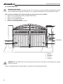
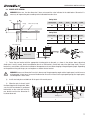
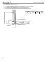
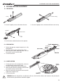
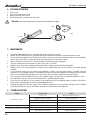
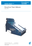
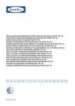
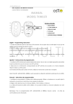
Operator SWING-3000/5000 Installation and Operating Manual © DoorHan, 2014 contents 2 General Information 2 Safety instructions 3 Operator unit 5 Operator Installation 5 Extreme Positions Adjustment 9 Release Operation 10 maintenance 10 Troubleshooting 10 Contents CONTENTS 1. General Information. . . . . . . . . . . . . . . . . . . . . . . . . . . . . . . . . . . . . . . . . . . . . . . . . . . . . . . . . . . . . . . . . . . . . . . . . . . . 2 1.1. Range of use . . . . . . . . . . . . . . . . . . . . . . . . . . . . . . . . . . . . . . . . . . . . . . . . . . . . . . . . . . . . . . . . . . . . . . . . . . . . . . . . . 2 1.2. Technical specifications. . . . . . . . . . . . . . . . . . . . . . . . . . . . . . . . . . . . . . . . . . . . . . . . . . . . . . . . . . . . . . . . . . . . . . . . . 3 1.3. Operator package . . . . . . . . . . . . . . . . . . . . . . . . . . . . . . . . . . . . . . . . . . . . . . . . . . . . . . . . . . . . . . . . . . . . . . . . . . . . . . 3 2. Safety instructions . . . . . . . . . . . . . . . . . . . . . . . . . . . . . . . . . . . . . . . . . . . . . . . . . . . . . . . . . . . . . . . . . . . . . . . . . . . . 3 3. Operator unit . . . . . . . . . . . . . . . . . . . . . . . . . . . . . . . . . . . . . . . . . . . . . . . . . . . . . . . . . . . . . . . . . . . . . . . . . . . . . . . . . . 5 4.operator installation . . . . . . . . . . . . . . . . . . . . . . . . . . . . . . . . . . . . . . . . . . . . . . . . . . . . . . . . . . . . . . . . . . . . . . . . . . 5 4.1. Tools. . . . . . . . . . . . . . . . . . . . . . . . . . . . . . . . . . . . . . . . . . . . . . . . . . . . . . . . . . . . . . . . . . . . . . . . . . . . . . . . . . . . . . . . 5 4.2. Installation layout. . . . . . . . . . . . . . . . . . . . . . . . . . . . . . . . . . . . . . . . . . . . . . . . . . . . . . . . . . . . . . . . . . . . . . . . . . . . . . 6 4.3. Inward gate opening. . . . . . . . . . . . . . . . . . . . . . . . . . . . . . . . . . . . . . . . . . . . . . . . . . . . . . . . . . . . . . . . . . . . . . . . . . . . 7 4.4. Outward gate opening. . . . . . . . . . . . . . . . . . . . . . . . . . . . . . . . . . . . . . . . . . . . . . . . . . . . . . . . . . . . . . . . . . . . . . . . . . . 8 5.Extreme Positions Adjustment. . . . . . . . . . . . . . . . . . . . . . . . . . . . . . . . . . . . . . . . . . . . . . . . . . . . . . . . . . . . . . . . . . . 9 5.1. Preparation. . . . . . . . . . . . . . . . . . . . . . . . . . . . . . . . . . . . . . . . . . . . . . . . . . . . . . . . . . . . . . . . . . . . . . . . . . . . . . . . . . . 9 5.2. Open position. . . . . . . . . . . . . . . . . . . . . . . . . . . . . . . . . . . . . . . . . . . . . . . . . . . . . . . . . . . . . . . . . . . . . . . . . . . . . . . . . 9 5.3. Closed position. . . . . . . . . . . . . . . . . . . . . . . . . . . . . . . . . . . . . . . . . . . . . . . . . . . . . . . . . . . . . . . . . . . . . . . . . . . . . . . . 9 6. Release Operation . . . . . . . . . . . . . . . . . . . . . . . . . . . . . . . . . . . . . . . . . . . . . . . . . . . . . . . . . . . . . . . . . . . . . . . . . . . . . 10 7. Maintenance . . . . . . . . . . . . . . . . . . . . . . . . . . . . . . . . . . . . . . . . . . . . . . . . . . . . . . . . . . . . . . . . . . . . . . . . . . . . . . . . . . 10 8. Troubleshooting . . . . . . . . . . . . . . . . . . . . . . . . . . . . . . . . . . . . . . . . . . . . . . . . . . . . . . . . . . . . . . . . . . . . . . . . . . . . . . 10 1. General Information The electromechanical linear operator Swing-3000/5000 is intended for automation of a street double-leaf swinging gate with a load-bearing structure. The body of the operator, which consists of two silumin parts, houses a motor, a reducer and a lead screw. The operator is equipped with built-in electrical limit switches for opening and closing. A self-blocking system, consisting of a worm gear and a planetary gearbox blocks the gate leaves, if the motor is off. The easyto-use and safe release system allows the gate leaves to be opened/closed manually, in case of a power cut or control unit failure. Operation of the automatic system is controlled from a remote control unit in a shockproof hermetic case. 1.1. Range of use Swing-3000 2 Swing-5000 Leaf width, m Leaf weight, kg Leaf width, m Leaf weight, kg 2.00 400 2.00 500 2.50 300 2.50 400 3.00 200 3.00 300 4.00 250 5.00 200 Safety instructions 1.2. Technical specifications Operator Swing-3000 Swing-5000 Weight, kg 10 11 Supply voltage, V/Hz 220–240/50 Rated power, W 150 Intensity, % 50 Protection rating IP54 Gear ratio 1/36 Rod speed, mm/s 15 Force, N 3 000 Working temperature range, °C –40…+55 Capacitor, mf 10 1.3. Operator package Upon receiving the operator, unpack it and inspect it carefully. If any signs of damage are observed, please contact your supplier. The operator components included in the standard package are listed in the following table. № Name Quantity 1 Operator 2 2 Rear fastening bracket 2 3 Front fastening bracket 2 4 Set of fasteners 1 5 Control unit with case 1 6 Keyswitch 1 7 Signal lamp 1 8 Photo cells 1 9 User manual 1 2. Safety instructions WARNING! Important safety instructions! It is important for the safety of persons to follow safety instructions. Save these instructions. Follow all instructions since incorrect installation can lead to severe injury. Swing-3000/5000 was designed for automation of a street doubleleaf swinging gate with a loadbearing structure. Do not use the operator for other than intended purposes. DoorHan shall not be held responsible in case of injury caused by misuse of the product. Prior to installation make sure that the gate moves smoothly. Installation must be performed in accordance with the standards EN12453 and EN 12445. For countries, which are not EC members, these requirements are to be met. Check if the gate conforms to the standards EN12604 and EN 12605 (see documentation accompanying the gate). For countries, which are not EC members, the above mentioned requirements shall be met in order to obtain an appropriate safety level. 3 Safety instructions Mechanical units of the gate shall conform to the standards EN12604 and EN 12605. Prior to installation, check that the location of operator installation is suitable by its climatic conditions to technical specifications of the operator. Do not install the operator in premises containing quick inflammable substances or other dangerous environments as it can cause explosion or fire. During assembly, installation and adjustment use tools specified in section “Tools” of this manual. When performing operation at height, use a stable support. The operator is not intended for installation at a height exceeding 2.5 m. When drilling holes, use protection for hands and eyes. For fastening of the item, use hardware supplied with the operator or other analogous one. Disconnect the supply when cleaning or other maintenance is being carried out, if the appliance is automatically controlled. If the operator is installed on the gate with a wicket door an additional safety device should be used to prevent operator activation when the wicket door is open. Ensure that entrapment between the driven part and the surrounding fixed parts due to the opening movement of the driven part is avoided. It is highly recommended to use DoorHan optional equipment as the accessories produced by other manufacturers can damage the automated system. DoorHan is not responsible for unstable work of the automatic system when using safety devices and accessories, which are produced by other manufactures without agreement with DoorHan. Never leave the electric motors in released condition. This may cause uncontrolled movement of the gate leaves and, consequently, their breakdown. Do not use the operator if it needs repair or adjustment as installation defects or unbalanced door can cause injury. DoorHan shall not be held liable in case of improper installation of the item and damage arisen during operation. Since the operator does not have a power cord with a plug it shall be connected to the mains supply via automatic switch with a minimal distance of 3 mm between the neighboring contacts. It is recommended to use a 10 А double-pole circuit breaker. Be sure there are no obstructions to door travel. Do not make any changes in the automatic system not specified in this manual. Remove package of the item and dispose of it. Keep the package materials away from children. Always keep remote controls out of reach of children. Never permit children to operate or play with garage door control push buttons or remote controls. No one should cross the pass of the moving door. The content of the manual shall not be basis for any claim. The manufacturer reserves the right to modify the design of the product described in this manual without preliminary notice. Warning! For safe and correct operation of the operator it is necessary to install mechanical stoppers to limit gate wing travel. 4 Operator unit 3.Operator unit Nut M8 Гайка М8 5 6 1. 2. 3. 4. 5. 6. 2 1 4 M8×10 Operator Front bracket Rear fork Rear bracket Release unit Lead screw M8×50 3 Swing-3000 88 126 793 300 Stroke Swing-5000 88 126 993 500 Stroke 4. operator installation 4.1.Tools 1 2 1. 2. 3. 4. 5 Set of spanners Set of slotted and cross screwdrivers Set of drills for metal Set of drills for concrete 6 3 5. 6. 7. 8. 4 Pliers Hacksaw for metal Electric drill Tape measure (folding rule) 7 8 5 operator installation 4.2.iNSTALLation layout Warning! RISK OF INJURY! Have a qualified technician lay the cables 220-240 V AC. The cables must be laid in protective corrugated tubes. Avoid contact of cables and moving parts of the door. In case of supply cable damage, use the suitable type of the cable. Cables needed for installation of the Swing-3000/5000 operator and accessories (if available): cable 2 × 0.5 mm2 (photocell transmitter, stepped control button); cable 2 × 1.5 mm2 (signal lamp); cabel 4 × 0.5 mm2 (photocell receiver); cable 3 × 1.5 mm2 (power supply); the cables should be appropriately insulated. 2 × 1,5 mm2 5 4 2 × 0,5 mm2 3 2 4 × 0,5 mm2 2 3 × 1,5 mm2 (220–240 V) 1 m2 ,5 m 3 × 1 m2 ,5 m 3 × 1 2 × 0 ,5 m m2 1 1. Operators 2.Photocells 3.Control block 4. Keyswitch 5. Signal lamp warning! Before installation make sure, that the gate moves freely and it is possible to install the operator on the pole and the leaf securely. Operator installation procedures are given below in accordance with the gate opening direction. 6 operator installation 4.3. Inward gate opening Warning! Make sure, that the dimension C does not exceed the value indicated in the table below. Otherwise it is necessary to improve the pole according to the indicated dimension value. Swing-3000 Pole Hinge Opening angle A, mm B, mm Cмакс, mm D, mm 90° 130 130 60 720 120° 130 110 50 720 Opening angle A, mm B, mm Cмакс, mm D, mm 90° 200 200 120 920 120° 200 140 70 920 Gate leaf (closed) Swing-5000 D Mounting plate Mounting plate A A Moving end part Rear bracket B Rear bracket B 1)Fasten the rear bracket with the appropriate fastening plate to the pole, as shown in the picture above, observing dimensions A and B, namely, the distance between the axis of the bracket’s central hole and of the gate hinge shank. The rear bracket has several holes, which make installation of the operator easier and allow changing of the gate opening angle. Depending on the position of the gate hinges you can lengthen or shorten the rear bracket. Warning! Increase of dimension B results in decrease of the gate opening angle and leaf angle speed, and in increase of the operator’s linear force. Increase of the dimension B results in increase of the gate opening angle, leaf angle speed, and the operator’s linear force. 2) Install steel end piece and lubricate all the parts with neutral grease. 3) When the gate is closed, install the mounting plate on the gate leaf. Make sure, that the front bracket is positioned horizontally on the same level with the rear bracket and that the dimension D has been observed. Mounting plate Mounting plate Building level Building level D Front bracket D Front bracket 7 Electrical Connections 4.4. Outward gate opening (SWING-5000) 1)Position the rear bracket in accordance with the dimensions A and B, listed in the table. 2) Install and fasten the rear bracket to the pole using an additional bracket. 3) Open the gate, measure distance D and fasten the front bracket to the gate leaf. A, mm B, mm D, mm 90 130 130 920 D Opening angle B External of theобъекта object Наружняяside сторона Additional Дополнительный bracket кронштейн 8 Internal side сторона of the object Внутренняя объекта A Extreme Positions Adjustment 5.Extreme Positions Adjustment 5.1. Preparation Screw casing Cover 1. Unscrew 2 tapping screws and remove the cover. 2. Unscrew 2 tapping screws and remove the lead screw casing. Nut M8 Lead screw 3. Install the front and back brackets on the operator. 5.2. Open position 1. Release the operator and put the gate leaf in fully open position. 2. Unscrew fastening of the opening limit switch. 3. Move the limit switch along the guide, until the microswitch contacts with the slide. 4. Fix the microswitch. 5.3. Closed position 1. Put the gate leaf in fully closed position, which can be determined by the mechanical stop. 2. Unscrew fastening of the closing microswitch. 3. Move the end microswitch along the guide until the microswitch contacts with the slide. 4. Move the microswitch ahead until the microswitch finger leaves response area. 5. Fix the microswitch. Warning! When the end positions are adjusted, make sure, that the limit switches work correctly: after pressing the microswitch the gate movement should be stopped. 9 Release Operation 6. Release Operation 1. 2. 3. 4. Lift the cover. Insert the key and turn it by 180° Open or close the gate by hand. To link the operator, turn the key by 180° again. Warning! Before releasing (linking) the operator, disconnect power supply. Key 180° Cover 7. Maintenance The Swing-3000/5000 automatic system does not require any special servicing. Repairs may be carried out only by a qualified technician trained and certified at an authorized DoorHan centre. Be sure that after completion of installation the installer has shown the user how to release the door in case of emergency and has given instructions on proper operation and maintenance of the automated system. When carrying out maintenance, it is recommended to use DoorHan original spare parts. Carry out maintenance of the automatic system at least every six months. Regularly check if the door is properly balanced and moves smoothly when automatically operated. Regularly check if the extreme positions of door travel are properly adjusted and safety devices are in good working condition. In case of power failure you may need to restore operator’s settings. Once the power supply is restored, check the automatic system for proper operation. If the operator settings have changed reprogram them following the instructions given in the corresponding paragraph of this manual (pay special warning to Operation time programming). In case of power failure the door will stop. As soon as power supply is restored you can control the operator as usual. After expiration of life time, the item shall be delivered in a specialized disposal point! If you have lost this Manual, you may request for the duplicate copy to the following address: Kralovsky VRCH 2018, Kadan, 43201, Czech Republic, or by email: [email protected]. The producer (DoorHan) does not supervise the installation of operators, or carry out their maintenance, thus DoorHan cannot be held liable for safety of installation, operation and maintenance of the equipment. 8. Troubleshooting Symptom Operator does not run Operator stops suddenly The gate does not open or close completely 10 Possible reason Solution Power is off Make sure, that the power is on Obstruction at gate’s movement Remove the obstruction Bad wiring connection Check reliability of electric wiring connection Operator is released Engage the operator Thermal protection is active Let the operator cool Wrong adjustment of limit switches Adjust the limit switches Wrong operator programming Reprogram the operator Notes Notes 12 Notes 13 We very much appreciate that you have chosen the product manufactured by our company and believe that you will be satisfied with its quality. For information on purchasing, distribution and servicing contact DoorHan central office at: Kralovsky VRCH 2018, Kadan, 43201, Czech Republic Telephone: +420 474 319 111 E-mail: [email protected] www.doorhan.cz