1
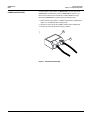
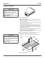
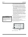
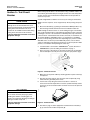
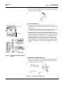
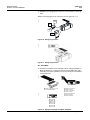
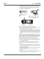
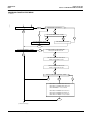
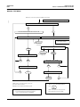
Instruction Bulletin
Universal Test Set
48040-976-02
03/01
Cedar Rapids IA, USA
K442
Universal Test Set
48040-976-02
03/01
NOTICE
Read these instructions carefully and look at the equipment to become familiar with the device before trying to install, operate,
service or maintain it. The following special messages may appear throughout this bulletin or on the equipment to warn of potential
hazards or to call attention to information that clarifies or simplifies a procedure.
The addition of either symbol to a “Danger” or “Warning” safety label indicates that an electrical hazard
exists which will result in personal injury if the instructions are not followed.
!
This is the safety alert symbol. It is used to alert you to potential personal injury hazards. Obey all safety
messages that follow this symbol to avoid possible injury or death.
!
DANGER
DANGER indicates an imminently hazardous situation which, if not
avoided, will result in death or serious injury.
! WARNING
WARNING indicates a potentially hazardous situation which, if not
avoided, can result in death or serious injury.
! CAUTION
CAUTION indicates a potentially hazardous situation which, if not
avoided, can result in minor or moderate injury.
CAUTION
CAUTION, used without the safety alert symbol, indicates a potentially
hazardous situation which, if not avoided, can result in property damage.
NOTE: Provides additional information to clarify or simplify a procedure.
PLEASE NOTE:
Electrical equipment should be installed, operated, serviced and maintained by qualified electrical
personnel. This document is not intended as an instruction manual for untrained persons.
FCC NOTICE:
This equipment has been tested and found to comply with the limits for a Class A digital device, pursuant
to part 15 of the FCC Rules. These limits are designed to provide reasonable protection against harmful
interference when the equipment is operated in a commercial environment. This equipment generates,
uses, and can radiate radio frequency energy and, if not installed and used in accordance with the
instruction manual, may cause harmful interference to radio communications. Operation of this
equipment in a residential area is likely to cause harmful interference in which case the user will be
required to correct the interference at his own expense.
2
© 1993-2001 Schneider Electric All Rights Reserved
48040-976-02
03/01
Table of Contents
©1993– 2001 Schneider Electric All Rights Reserved
Universal Test Set
Table of Contents
Section 1—General Information ............................................................. 4
Applications........................................................................................ 4
Terminology ....................................................................................... 5
Test Types ......................................................................................... 5
Zone Interlocks and Self-Restraint..................................................... 6
POWERLOGIC System ..................................................................... 7
Section 2—Self-Test ............................................................................... 8
Section 3—Test Circuit Breaker ........................................................... 10
Section 4—MICROLOGIC Series B CBTMB Test Module ................... 14
Test Setup........................................................................................ 14
Test Setup for Full-function Circuit Breakers ................................... 15
Test Setup for Standard-function Circuit Breakers .......................... 16
Main Test Menu ............................................................................... 17
Automatic Test Menu for all Circuit Breakers without
Ground-fault Alarm ..................................................................... 18
Automatic Test Menu for Circuit Breakers with
Ground-fault Alarm..................................................................... 19
Individual Test Menu for All Full-function Circuit Breakers without
Ground-fault Alarm .................................................................... 20
Individual Test Menu for Full-function Circuit Breakers
with Ground-fault Alarm............................................................. 22
Individual Test Menu for All Standard-function Circuit Breakers...... 24
Manual Test Menu For All Full-function Circuit Breakers
without Ground-fault Alarm ........................................................ 26
Manual Test Menu for Full-function Circuit Breakers with
Ground-fault Alarm..................................................................... 27
Manual Test Menu for All Standard-function Circuit Breakers ......... 28
Section 5—M-N-P-S CBTM4A Test Module ......................................... 29
Test Setup for Full-function Circuit Breakers ................................... 29
Test Setup for Standard-function Circuit Breakers .......................... 30
Main Test Menu ............................................................................... 31
Automatic Test Menu for Full-function Circuit Breakers................... 32
Automatic Test Menu for Standard-function Circuit Breakers.......... 33
Individual Test Menu for Full-function Circuit Breakers ................... 34
Individual Test Menu for Standard-function Circuit Breakers........... 36
Manual Test Menu for Full-function Circuit Breakers....................... 37
Manual Test Menu for Standard-function Circuit Breakers .............. 38
Section 6—SE CBTM1 Test Module .................................................... 39
Test Setup........................................................................................ 39
Automatic Test Menu ....................................................................... 40
Individual-function Test Menu .......................................................... 41
Manual Test Menu ........................................................................... 44
Section 7—ME-NE-PE CBTM3 Test Module ....................................... 45
Test Setup........................................................................................ 45
Automatic Test Menu ....................................................................... 46
Individual-function Test Menu .......................................................... 47
Manual Test Menu ........................................................................... 51
Index ..................................................................................................... 52
3
Universal Test Set
Section 1—General Information
48040-976-02
03/01
Section 1—General
Information
APPLICATIONS
CAUTION
HAZARD OF EQUIPMENT DAMAGE
Before using the test set, do the self-test to
insure proper test set operation.The self-test is
described in Section 2 of this manual.
Failure to follow this instruction can result in
equipment damage.
The Universal Test Set is designed to perform operational tests and
diagnoses of Square D electronic trip circuit breakers, circuit breaker
components and tripping functions. It does not check the primary current
sensing capabilities of a circuit breaker.
Check the following table to find the appropriate test set/test module for the
circuit breaker.
Table 1: Test Set/Test Module
Circuit Breaker
Circuit Breaker
Series Number
Test Set
Test Module1
LE/LX
1B
CBTU1 or UTS3
CBTMB
ME
1 and 2
CBT78
Not Available - Primary
Injection Testing Only
MX
NE
NX
PE
CBTU1 or UTS3
CBTM3
CBTU1 or UTS3
CBTM4 or CBTM4A
5A
CBTU1 or UTS3
CBTM4A
5B
CBTU1 or UTS3
CBTMB
4 and 5
CBTU1 or UTS3
CBTM4 or CBTM4A
5B
CBTU1 or UTS3
CBTMB
1
CBTU1 or UTS3
CBTM3
2 and 3
CBTU1 or UTS3
CBTM4 or CBTM4A
3A
CBTU1 or UTS3
CBTM4A
3B
CBTU1 or UTS3
CBTMB
2 and 3
CBTU1 or UTS3
CBTM4 or CBTM4A
3B
CBTU1 or UTS3
CBTMB
CBT78
Not Available - Primary
Injection Testing Only
1,2, and 3
PX
SE
3
4 and 5
1
4
CBTU1 or UTS3
CBTM3
5 and 6
CBTU1 or UTS3
CBTM4 or CBTM4A
6A
CBTU1 or UTS3
CBTM4A
6B
CBTU1 or UTS3
CBTMB
5 and 6
CBTU1 or UTS3
CBTM4 or CBTM4A
6B
CBTU1 or UTS3
CBTMB
CBTSE1
Not Available - Primary
Injection Testing Only
2
CBTU1 or UTS3
CBTM1
3
CBTU1 or UTS3
CBTM4 or CBTM4A
3A
CBTU1 or UTS3
CBTM4A
3B
CBTU1 or UTS3
CBTMB
1
A kit including the umbilical cord and rating plug adapter is available for each test module.
The umbilical cord and rating plug adapter connect the test set to the circuit breaker being tested.
A power cord (Part No. 48005-115-01) and an umbilical cord (Part No. 48155-055-50) are also
available as replacement parts.
4
© 1993-2001 Schneider Electric All Rights Reserved
48040-976-02
03/01
TERMINOLOGY
Universal Test Set
Section 1—General Information
The following terms are used in diagnosing circuit breaker functions:
LONG-TIME PICKUP. The current at which thelong-time delay timer starts.
LONG-TIME AMPERE RATING. The current carrying capacity or “handle
rating” of the circuit breaker.
LONG-TIME DELAY. The time period that the long-time delay timer runs
before initiating a trip signal, i.e., the length of time the circuit breaker will
carry a sustained low-level overload before initiating a trip signal.
SHORT-TIME PICKUP. The current at which the short-time delay timer starts,
i.e., the current at which the short-time function recognizes an overcurrent.
SHORT-TIME DELAY. The time period short- time delay timer runs before
initiating trip signal, i.e., the short-time delay allows the circuit breaker to
carry or withstand low-level or high-level short- circuit currents (up to the
published withstand ratings) with intentional delay before tripping. There are
two choices of short-time delay characteristics available:
1.I2t IN. A delay characteristic which results in an inverse-time delay that
most closely parallels time-current characteristics of fuses.
2.I2t OUT. A delay characteristic which results in a constant delay that
coordinates best with thermal-magnetic and electronic trip circuit
breakers.
GROUND-FAULT PICKUP. The ground-fault current level at which groundfault delay timer starts, i.e., the function which allows the user to set the level
of ground-fault current at which the trip system begins timing.
GROUND-FAULT DELAY. The time period the ground-fault delay timer runs
before initiating trip signal, i.e., the function which determines the time the
circuit breaker will wait before initiating a trip signal. There are two choices
of ground-fault delay characteristics available:
1.I2t IN. A delay characteristic which results in an inverse-time delay that
coordinates best with zero sequence ground-fault relays used in
conjunction with thermal-magnetic circuit breakers and fusible switches.
2.I2t OUT. A delay characteristic which results in a constant delay
characteristic that coordinates best with electronic trip circuit breakers
with the ground-fault option.
GROUND-FAULT ALARM PICKUP. The ground-fault current level at which
the trip unit initiates a signal to indicate a ground-fault condition. The circuit
breaker will not trip.
TEST TYPES
The Universal Test Set provides three test options for each type of circuit
breaker tested. These test types are: Automatic Test Mode, IndividualfunctionTest Mode, and Manual Test Mode. The information which follows
explains the requirements for and the results obtained by each test.
NOTE: A small straight-blade screwdriver is required for testing circuit
breakers.
Automatic Test Mode
TEST REQUIREMENTS: Circuit breaker, rating plug and trip unit
information.
TEST RESULTS: Tests long-time, short-time, instantaneous and groundfault functions simultaneously without pauses or prompts; displays the
amount of time delay before initiating the trip signal. Specifies which function
failed on a pass/fail basis.
© 1993-2001 Schneider Electric All Rights Reserved
5
Universal Test Set
Section 1—General Information
Individual-function Test
Mode
48040-976-02
03/01
TEST REQUIREMENTS: Circuit breaker, rating plug and trip unit
information. Selection of the specific function(s) to be tested. The Individualfunction test mode is accessed from the automatic test mode.
TEST RESULTS: Displays and diagnoses functions one at a time; tests each
trip unit switch function as well as the operation of the indicators. Tests
calibration and tolerance to predetermined values.
Manual Test Mode
CAUTION
HAZARD OF EQUIPMENT DAMAGE
TEST REQUIREMENTS: Circuit breaker, rating plug and trip unit
information. A phase or ground- fault current value must be manually
entered.
TEST RESULTS: Monitors and displays the trip time of the selected current
applied to the trip unit.
Before using the test set, do the self-test on the
testing unit to insure proper test set operation.
The self-test is described in Section 2 of this
manual.
Failure to follow this instruction can result in
equipment damage.
ZONE INTERLOCKS AND
SELF-RESTRAINT
Some testing procedures require the zone interlocks or any self-restraint
jumper wires to be disconnected. If the circuit breaker is wired for zone
interlocking or is self-restrained by jumper wires, do the following:
LE, ME, NE and PE Circuit Breakers
Refer to table 2 and disconnect wires or jumpers from terminals 6 and 8 of
the terminal block. Reconnect the wires when testing is complete.
Table 2: Terminal Numbering
Number
Terminal Name
5
6
ST Restraint OUT
7
8
GF Restraint OUT
9
SE Circuit Breakers
Refer to table 3 and disconnect wires or jumpers from terminals 21 and 24 of
the teminal block. Reconnect the wires when testing is complete.
Table 3: Terminal Numbering
Number
Terminal Name
19
20
21
Ground-fault Zone Interlock
22
23
24
Short-time Zone Interlock
25
6
© 1993-2001 Schneider Electric All Rights Reserved
48040-976-02
03/01
POWERLOGIC SYSTEM
Universal Test Set
Section 1—General Information
If circuit breaker is connected to a POWERLOGIC® system, disconnect
POWERLOGIC system before testing. If POWERLOGIC system is not
disconnected, Universal Test Set will show “TEST FAILED” message.
Disconnect POWERLOGIC system by doing the following steps:
1. Mark connector (A) in figure 1 at CIM3F communications adapter (B) in
figure 1 for circuit breaker before being tested.
2. Disconnect connector (A) from CIM3F communications adapter (B).
05903028
3. Reconnect connector (A) when testing is complete.
B
A
Figure 1: Communication Adapter
© 1993-2001 Schneider Electric All Rights Reserved
7
Universal Test Set
Section 2—Self-test
48040-976-02
03/01
05903029
Section 2—Self-Test
CAUTION
HAZARD OF EQUIPMENT DAMAGE
DO NOT touch connector pins (Fig.2) when
handling test modules. Touching pins can
produce an electrostatic discharge resulting in
damage to module or trip unit.
Failure to follow this instruction can result in
equipment damage.
Figure 2: Connector pins
1. Place universal test set (fig. 3) on a flat surface. Open case until cover
locks into the open position.
2. Make sure test set power is off (O) by checking position of power switch
(A, Fig. 3) on keyboard (F).
3. Plug one end of test set power cord into power cord receptable (B); plug
other end into a grounded power source.
4. Insert Self-test Module (D) into module receptacle (E) in upper right
corner of test set. Make sure module label is facing keyboard (F). Never
use receptacle for storing modules when test set is not in use; use only
module holders (C) for storage.
5. Turn power switch (A) to on (I). The red light on self-test module will glow
and an identifying message will appear on the display.
6. The module will run automatically for a short period of time to insure basic
operations of test set are working correctly.
NOTE: If an error message occurs or module light fails to come on, turn
power to off (O) and carefully re-seat module in receptable.
HAZARD OF EQUIPMENT DAMAGE
Test results will be inaccurate if any self-test is
unsuccessful. Do not use test set to test circuit
breakers if any self-test, including those which
follow, is unsuccessful.
7. If tests were successful, test set can now be used for testing circuit
breakers.
05903030
CAUTION
D
E
F
Failure to follow this instruction can result in
equipment damage.
A
C
B
Figure 3: Universal Test Set
8
© 1993-2001 Schneider Electric All Rights Reserved
48040-976-02
03/01
Universal Test Set
Section 2—Self-test
8. The test set will now prompt for optional manual testing of functions.
These tests must be done on a periodic basis. To test functions, see
steps 9 and 10. If manual tests are not being done, go to step 11.
9. Press keys slowly and firmly. Press SET UP key when it is flashing to
return test set to the beginning of the following self-test sequence:
a.“TEST SYSTEM KEYBOARD?-YES/NO” checks keyboard to make
sure it is accepting input correctly. If keyboard is not being tested, press
NO key. To test operation of keyboard, press YES key. The display will
then step through the test. If display indicates “SYSTEM KEYBOARD
FAILED,” see step 10A.
b.“TEST SYSTEM KEY LIGHTS?-YES/NO” checks the systems key
backlights for proper operation. If backlights are not being tested, press
NO key. To check operation of backlights, which are located behind the
eight system keys (A) in Figure 4, press YES key. The display will step
through the test with lights flashing in sequence down the rows. If
display indicates “SYSTEM LIGHTS TEST FAILED,” see step 10A.
c. “TEST SYSTEM L.C.D. DISPLAY?-YES/NO” checks for proper
operation of LCD (liquid crystal display) characters. If LCD is not being
tested, press NO key. To test LCD, press YES key. Display will then
step through the test. If display indicates “SYSTEM L.C.D DISPLAY
TEST FAILED,” see step 10A.
10. Test set will now display test results:
a.If test sequence was not successful, display will so indicate. Press SET
UP key to return test to beginning of test sequence and run tests again.
If test sequence is again unsuccessful, note message and contact
Square D for assistance (1-888-778-2733).
CAUTION
HAZARD OF EQUIPMENT DAMAGE
Test results will be inaccurate if any self-test is
unsuccessful. Do not use test set to test circuit
breakers if any self-test was unsuccessful.
Failure to follow this instruction can result in
equipment damage.
b. If test sequence was successful, Universal Test Set can now be used
to test circuit breaker trip systems.
11. Turn test set power switch (B) in Figure 4 to OFF.
12. Remove self-test module and store it in module holder.
05903031
13. If no additional testing is planned, unplug test set, store power cord in
storage area, and close test set case.
NO TRIP
YES
1
2
3
SET
NO
4
5
6
NEXT
A
7
8
9
TEST
TYPE
B
CLEAR
0
TRIP
ON
B
OFF
POWER
ENTER
MANUAL
A
Figure 4: Test System Console
© 1993-2001 Schneider Electric All Rights Reserved
9
Universal Test Set
Section 3—Test Circuit Breaker
Section 3—Test Circuit
Breaker
CAUTION
HAZARD OF EQUIPMENT DAMAGE
Damage to test set and module will occur if
current is flowing through circuit breaker during
testing. Disconnect all loads from circuit
breaker. Do not CLOSE circuit breaker during
testing unless all loads are disconnected.
Failure to follow this instruction can result in
equipment damage.
48040-976-02
03/01
When testing only SE Series 2 circuit breakers using a CBTM1 module, test
set conducts ground-fault delay test using dc current. As a result, delay times
are 20% shorter than circuit breaker would provide in actual operation as
shown on trip curves.
A small straight-blade screwdriver is necessary for testing circuit breakers.
NOTE: The test sequence can be stopped at any time by turning test power
OFF.
1. Disconnect all loads by (1) placing circuit breaker in OPEN position or (2)
disconnecting all loads downstream from circuit breaker under test.
NOTE: During test there must be no current flowing through circuit breaker.
Any current flowing through circuit breaker will terminate test and could result
in damage to test set. If circuit breaker is in OPEN position, trip solenoid test
cannot be done. If downstream loads are disconnected, circuit breaker can
be in either OPEN or CLOSED position. If circuit breaker is in CLOSED
position, it will trip during functional tests depending upon position of TRIP/
NO TRIP switch. If switch is placed in NO TRIP position, test set will not
signal circuit breaker to trip during functional tests. If switch is placed in TRIP
position, circuit breaker will trip during functional tests.
2. If circuit breaker is connected to POWERLOGIC® system, disconnect
POWERLOGIC system according to instructions on page 7.
05903030
3. Place test set on a flat surface no more than five feet from circuit breaker
to be tested. Open case fully to lock cover into the open position (fig.5).
C
D
A
B
Figure 5: Universal Test Set
4. Make sure test set power is OFF by checking position of power switch (A)
on keyboard.
5. Plug test set power cord into test set power cord receptacle (B). Plug
other end into a grounded power source.
CAUTION
05903029
6. Test the test set by doing the self-test in Section 2. If self-test is
unsuccessful contact Square D for assistance (1-888-778-2733) and do
not use test set to test circuit breaker. If self-test was successful, proceed
with step 7.
HAZARD OF EQUIPMENT DAMAGE
Do not touch connector pins (Fig. 6) when
handling test modules. Touching pins can
produce an electrostatic discharge resulting in
damage to module or trip unit.
Failure to follow this instruction can result in
equipment damage.
Figure 6: Connector Pins
7. See table on page 4. Select appropriate circuit breaker test module (C,
fig. 5) and insert into module receptacle (D).
10
© 1993-2001 Schneider Electric All Rights Reserved
48040-976-02
03/01
Universal Test Set
Section 3—Test Circuit Breaker
05903032
8. Insert test set end of umbilical cord into slot on top of module as shown
by label on module. The umbilical cord is inserted with cable toward rear
of module as shown in figure 7.
Figure 7: Umbilical Cord
ME Series 3
A
B
9. Circuit breakers with screw retained trip unit cover: Use a small
screwdriver to loosen trip unit cover screws (A) and remove clear plastic
trip unit cover.
Circuit breakers with snap-on trip unit cover. Insert a small screwdriver
under tab of clear plastic trip unit cover and snap out the cover.
A
SE Series 2
10. Circuit breakers with screw retained trip unit cover: To remove any
accumulated electrostatic charge, touch trip unit metal panel. Hold rating
plug (B), if equipped, firmly and SLOWLY remove it from circuit breaker.
Circuit breakers with snap-on trip unit cover: If equipped with a trip
indicator/ammeter (C), use a small screwdriver to carefully pry up one
end and then the other, a small amount at a time, to remove the trip
indicator/ammeter (C). On circuit breakers without trip indicator/ammeter,
remove the black plastic cover. Remove rating plug (D) or black plastic
cover.
B
A
NE Series 1
B
D
PE Series 4
Figure 8:
C
LE-ME-NE-PE-SE
with Snap-on Cover
Screw Retained and Snap-On Unit
Covers
TRIP UNITS WITH RATING PLUGS ONLY:
05903034
11. LIGHTLY touch rating plug connector board to metal grounding surface
(A, Fig. 9) next to power cord receptacle of test set to discharge any
accumulated electrostatic charge.
ME Series 3, NE
Series 2, or PE
Series 4 Rating Plug
A
SE Series 3 Rating
Plug
Figure 9:
© 1993-2001 Schneider Electric All Rights Reserved
Trip Units with Rating Plugs
11
Universal Test Set
Section 3—Test Circuit Breaker
48040-976-02
03/01
12. SLOWLY insert rating plug into connector on tip of module as shown by
label.
05903035
NOTE: The rating plug must be oriented as shown in figure 10 or 11.
OR
SE
XXXX
XXXX
ME
XXXX
XXXX
NE
XXXX
XXXX
PE
XXXXX
05903036
Figure 10: Rating Plug Insertion
Figure 11: Rating Plug Insertion
ALL TRIP UNITS:
05903037
13. Carefully insert adapter end of umbilical cord into rating plug adapter or
M-N-P-S Adapter (fig. 12) being careful not to bend adapter pins. Note
orientation of connector. (Adapters are stored in the power and umbilical
cord storage area).
05903073
ME Series 3, NE Series 1, PE
Series 4 and SE Series 2
ME Series,4. 5 and 5 A
MX Series 4 and 5
Ne Series 2, 3, and 3A
NX series 2 and 3
PE Series 5, 6, and 6A
PX Series 5 and 6
SE Series 3 and 3A
LE/LX Series 1B
MESeries 5B
MX Series 5B
NE Series 3B
NX Series 3B
PE Series 6B
PX Series 6B
SE Series 3B
Figure 12: Rating Plug Adapter and M-N-P-S Adapter
12
© 1993-2001 Schneider Electric All Rights Reserved
48040-976-02
03/01
Universal Test Set
Section 3—Test Circuit Breaker
14. Grasp adapter firmly and touch adapter connector board lightly against
metal grounding surface (A, fig. 9) next to power cord receptacle.
15. Immediately install adapter SLOWLY into trip unit. Note orientation of
umbilical cord and adapter (A, fig. 13).
05903038
A
A
ME Series, NE Series 1, PE
Series 4 and SE Series 2
A
LE/LX Series 1B
ME Series 5B
MX Series 5B
NE Series 3 B
ME Series 4,5 and 5A MX Series 4 and 5
NE Series 2,3, and 3A NX Series 2 and 3
PE Series 5, 6 and 6A PX Series 5 and 6
SE Series 3 and 3A
NX Series 3B
PE Series 6B
PX Series 6B
SE Series 3B
Figure 13: Orientation of Umbilical Cord and Adapter
16. Turn test set power switch on (I). The test set will perform a self-test. After
self-test, module identifier will be displayed.
17. Refer to test procedure for the test module being used and begin testing.
The test set will request information on frame size and trip unit function..
After all information has been entered and verified, test set will ask for
“TEST TYPE.” See section 1 for test type. Enter test type and continue
with test.
NOTE: If “TEST FAILED” message appears in the display window, check to
see if circuit breaker is connected to a POWERLOGIC system. If circuit
breaker is connected to POWERLOGIC system, disconnect POWERLOGIC
system according to instructions on page 7 and press A to repeat test. If
“TEST FAILED” appears again, call Square D (1-888-778-2733).
18. After test has been completed, turn test set power switch to off (O).
19. Slowly remove adapter from trip unit by holding adapter housing firmly
and removing it from trip unit.
20. Remove adapter from umbilical cord and store in storage space.
21. Remove umbilical cord from module. Store umbilical cord in storage
space.
22. Hold rating plug housing, if equipped, firmly and slowly remove it from the
module. Lightly touch rating plug connector to metal grounding surface
next to power cord receptacle.
23. Slowly insert rating plug and trip indicator/ammeter or black plastic covers
into slots in circuit breaker.
24. Replace clear trip unit cover and secure trip unit cover screws, if
equipped.
25. Remove test module and install in module holder. Do not touch connector
pins. Disconnect test set, store power cord, and close cover.
© 1993-2001 Schneider Electric All Rights Reserved
13
Universal Test Set
Section 4—MICROLOGIC Series B CBTMB Test Module
48040-976-02
03/01
Section 4—MICROLOGIC
Series B CBTMB Test
Module
TEST SETUP
05903039
***UNIVERSAL TEST SET*** ver 2.0
MICROLOGIC SERIES B MODULE ver 1.0
IS BREAKER A FULL-FUNCTION BREAKER?
NO
Go to Page 16
for Standard-function
Setup
YES
Go to Page 15
for Full-function
Setup
****ATTENTION****
BREAKER IS NOT MICROLOGIC SERIES B
ERROR: CURRENT DRIVER OVER VOLTAGE
TESTING CANNOT PROCEED - SEE INSTRUCTIONS
Turn test set power OFF (O). Remove and reseat test module. Check
connections of umbilical cord, rating plug and rating plug adapter.
Turn test set power ON (I) to restart test. If "TESTING CANNOT PROCEED"
message appears again, call Square D (1-888-778-2733.)
14
© 1993-2001 Schneider Electric All Rights Reserved
48040-976-02
03/01
Universal Test Set
Section 4—MICROLOGIC Series B CBTMB Test Module
05903040
TEST SETUP FOR FULL-FUNCTION
CIRCUIT BREAKERS
From Page 14
TESTING RATING PLUG
RATING PLUG TEST PASSED
RATING PLUG TEST FAILED
TESTING CANNOT PROCEED - SEE INSTRUCTIONS
The rating plug was found to be defective. Turn test set power
OFF (O) and then back ON (I) to restart test. If "TESTING CANNOT
PROCEED" message appears again, replace rating plug.
PLEASE ENTER FRAME SIZE ...0
ENTER
CLEAR
0-9 KEYS
IS SHORT-TIME INSTALLED? - YES/NO
NO
YES
IS GROUND-FAULT INSTALLED? - YES/NO
NO
YES
IS GROUND-FAULT AN ALARM? - YES/NO
NO
YES
ARPxxxx INSTALLED?
IS xE xxxxA LSG
NO
TESTING ME BREAKER? - YES/NO
YES
NO
TESTING NE BREAKER? - YES/NO
YES
NO
TESTING PE BREAKER? - YES/NO
YES
NO
TESTING SE BREAKER? - YES/NO
YES
NO
LSG
ME
ENTERED
NE
FRAME SIZE
PLEASE RECHECK BREAKER CONFIGURATION
LS
PE IS DISPLAYED
SE
YES
NO
YES
LE
TESTING LE BREAKER? - YES/NO
LIG
RATING PLUG LABEL
LI
LSA
OR RATING PLUG CONNECTION
LIA
OPTIONS DISPLAYED
Turn power to OFF (O) and then back ON (I) to restart test.
Go to page 17
*****MAIN TEST MENU*****
© 1993-2001 Schneider Electric All Rights Reserved
15
Universal Test Set
Section 4—MICROLOGIC Series B CBTMB Test Module
48040-976-02
03/01
TEST SETUP FOR STANDARDFUNCTION CIRCUIT BREAKERS
05903041
From Page 14
TESTING RATING PLUG
RATING PLUG TEST PASSED
RATING PLUG TEST FAILED
TESTING CANNOT PROCEED - SEE INSTRUCTIONS
The rating plug was found to be defective. Turn test set power
OFF (O) and then back ON (I) to restart test. If "TESTING CANNOT
PROCEED" message appears again, replace rating plug.
PLEASE ENTER FRAME SIZE ...0
CLEAR
ENTER
0-9 KEYS
IS GROUND-FAULT INSTALLED? - YES/NO
TESTING LX BREAKER? - YES/NO
NO
YES
TESTING MX BREAKER? - YES/NO
YES
NO
TESTING NX BREAKER? - YES/NO
NO
YES
YES
IS xX xxxx G
ARPxxxx INSTALLED?
NO
YES
NO
TESTING PX BREAKER? - YES/NO
YES
NO
LX
MX
ENTERED
NX
FRAME SIZE
PX
IS DISPLAYED
IS DISPLAYED
PLEASE RECHECK BREAKER CONFIGURATION
G
RATING PLUG LABEL
IS DISPLAYED
OR RATING PLUG CONNECTION
IF GROUND-FAULT
Go to page 17
OPTION
Turn power to OFF(O) and then back ON (I) to restart test.
*****MAIN TEST MENU*****
16
© 1993-2001 Schneider Electric All Rights Reserved
48040-976-02
03/01
Universal Test Set
Section 4—MICROLOGIC Series B CBTMB Test Module
05903042
MAIN TEST MENU
*****MAIN TEST MENU*****
TESTING BREAKER AUTOMATICALLY? -YES/NO
Continue with Automatic Test Menu
on page 18 for circuit breakers
NO
YES
without ground-fault alarm or on
page 19 for circuit breakers with
ground-fault alarm.
TEST INDIVIDUAL FUNCTIONS? YES/NO
Continue with Individual Test Menu
for the following:
Page 20 for all full-function circuit
NO
YES
breakers without ground-fault alarm,
Page 22 for full-function circuit
breakers with ground-fault alarm,
Page 24 for all standard-function
PERFORM MANUAL TESTING? - YES/NO
circuit breakers.
Continue with Manual Test Menu for the
NO
YES
following:
Page 25 for all full-function circuit
breakers without ground-fault alarm,
Description of Key Functions
Page 27 for full-function circuit
breakers with ground-fault alarm,
YES
VERIFIES DATA ENTERED/SHOWN
NO
NEGATIVE RESPONSE TO DATA SHOWN
A
ENTERED AFTER TRIP UNIT FUNCTION SWITCH IS SET
B
NOT USED
CLEAR
DELETES ENTRY
SET UP
NOT USED
ENTER
SIGNIFIES END OF ENTRY
NEXT
NOT USED
MANUAL
NOT USED
TEST
Page 28 for all standard-function circuit
breakers.
RETURNS UNIT TO MAIN TEST MENU
TYPE
NOTE: An option is valid any time its key is flashing.
NOTE: Test sequence can be stopped at any time by turning the test set power to OFF (O).
© 1993-2001 Schneider Electric All Rights Reserved
17
Universal Test Set
Section 4—MICROLOGIC Series B CBTMB Test Module
48040-976-02
03/01
AUTOMATIC TEST MENU FOR ALL
CIRCUIT BREAKERS WITHOUT
GROUND-FAULT ALARM
05903043
SET LONG-TIME PICKUP TO 1.00 xP
A
SET LONG-TIME DELAY TO MINIMUM
A
SET SHORT-TIME PICKUP TO 4 xP
A
SET SHORT-TIME DELAY TO I^2t IN .20sec
A
SET INSTANT. PICK UP TO 5 xP
A
SET GROUND-FAULT PICKUP TO .35 xS
OR
SET GROUND-FAULT PICKUP TO 880AMPS
A
SET GROUND-FAULT DELAY TO I^2t OUT .20sec
A
LONG-TIME PICKUP = n.nn xP
nnnnAMPS
LONG-TIME DELAY = nn.nnnsec
SHORT-TIME PICKUP = nn.nnxP nnnnnAMPS
SHORT-TIME DELAY = nn.nnnsec
INSTANT. PICKUP = nn.nnxP
nnnnnnAMPS
GROUND-FAULT PICKUP = n.nnxS nnnnAMPS
GROUND-FAULT DELAY = nn.nnnsec
ALL TESTED FUNCTIONS PASSED!
18
© 1993-2001 Schneider Electric All Rights Reserved
48040-976-02
03/01
Universal Test Set
Section 4—MICROLOGIC Series B CBTMB Test Module
AUTOMATIC TEST MENU FOR CIRCUIT
BREAKERS WITH GROUND-FAULT
ALARM
05903044
SET LONG-TIME PICKUP TO 1.00 xP
A
SET LONG-TIME DELAY TO MINIMUM
A
SET SHORT-TIME PICKUP TO 4 xP
A
SET SHORT-TIME DELAY TO I^2t IN .20sec
A
SET INSTANT. PICK UP TO 5 xP
A
SET GROUND-FAULT ALARM TO .35 xS
OR
SET GROUND-FAULT ALARM TO 880AMPS
A
LONG-TIME PICKUP = n.nn xP
nnnnAMPS
LONG-TIME DELAY = nn.nnnsec
SHORT-TIME PICKUP = nn.nnxP nnnnnAMPS
SHORT-TIME DELAY = nn.nnnsec
INSTANT. PICKUP = nn.nnxP
nnnnnnAMPS
GROUND-FAULT ALARM = n.nnxS nnnnAMPS
ALL TESTED FUNCTIONS PASSED!
© 1993-2001 Schneider Electric All Rights Reserved
19
Universal Test Set
Section 4—MICROLOGIC Series B CBTMB Test Module
48040-976-02
03/01
05903045
INDIVIDUAL TEST MENU FOR ALL
FULL-FUNCTION CIRCUIT BREAKERS
WITHOUT GROUND-FAULT ALARM
TEST LONG-TIME PICKUP?
YES
LONG-TIME PICKUP = nn.nnxP nnnnAMPS
A
NO
TEST LONG-TIME DELAY?
YES
SET SHORT-TIME PICKUP TO 4 xP
A
NO
SET INSTANT. PICKUP TO 5 xP
A
A
LONG-TIME DELAY = nn.nnnsec
YES
TEST SHORT-TIME PICKUP?
SET INSTANT. PICKUP TO MAXIMUM
A
NO
A
SHORT-TIME PICKUP = nn.nn xP nnnnnAMPS
TEST SHORT-TIME DELAY?
YES
SET LONG-TIME DELAY TO MAXIMUM
A
SET SHORT-TIME PICKUP TO 4 xP
NO
A
SET INSTANT. PICKUP TO 5 xP
A
SHORT-TIME DELAY = nn.nnnsec
A
YES
TEST UNRESTR. SHORT-TIME DELAY?
SET LONG-TIME DELAY TO MAXIMUM
A
SET SHORT-TIME PICKUP TO 4 xP
NO
A
SET INSTANT. PICKUP TO 5 xP
A
PLEASE DISCONNECT ZONE INTERLOCKS
See page 6 for
instructions
A
A
SHORT-TIME DELAY = nn.nnnsec
(Continued on next page)
20
© 1993-2001 Schneider Electric All Rights Reserved
48040-976-02
03/01
Universal Test Set
Section 4—MICROLOGIC Series B CBTMB Test Module
05903046
INDIViDUAL TEST MENU FOR
ALL FULL-FUNCTION CIRCUIT
BREAKERS WITHOUT GROUNDFAULT ALARMS (–Continued)
TEST INSTANT. PICKUP?
SET SHORT-TIME PICKUP TO MAXIMUM
YES
A
NO
SET SHORT-TIME DELAY TO I^2t IN .50 sec
A
A
TEST GROUND-FAULT PICKUP?
INSTANT. PICKUP = nn.nnxP nnnnnAMPS
YES
NO
GROUND-FAULT PICKUP = n.nnxS nnnnAMPS
A
TEST GROUND-FAULT DELAY?
YES
GROUND-FAULT DELAY = nn.nnnsec
A
NO
TEST UNRESTR. GROUND-FAULT DELAY?
PLEASE DISCONNECT ZONE INTERLOCKS
YES
A
See page 6 for instructions
NO
A
GROUND-FAULT DELAY = nn.nnnsec
YES
TEST TRIP SOLENOID?
PLEASE CLOSE THE BREAKER
A
NO
DID THE BREAKER TRIP?
YES
NO
TRIP SOLENOID TEST PASSED!
A
TRIP SOLENOID TEST FAILED
TEST TRIP UNIT MEMORY?
YES
SET LONG-TIME DELAY TO MINIMUM
A
SET SHORT-TIME PICKUP TO 4 xP
NO
A
SET SHORT-TIME DELAY TO I^2t IN .20 sec
A
SET INSTANT. PICKUP TO 5 xP
A
NOTE:
TEST
A
SET GND. FAULT DELAY TO I^2t OUT .20 sec
TYPE
A
Can be entered to exit
back to MAIN TEST MENU.
GROUND-FAULT MEMORY TEST FAILED!
MEMORY TEST PASSED!
© 1993-2001 Schneider Electric All Rights Reserved
SHORT-TIME MEMORY TEST FAILED!
LONG-TIME MEMORY TEST FAILED!
21
Universal Test Set
Section 4—MICROLOGIC Series B CBTMB Test Module
48040-976-02
03/01
05903045
INDIVIDUAL TEST MENU FOR FULLFUNCTION CIRCUIT BREAKERS WITH
GROUND-FAULT ALARM
TEST LONG-TIME PICKUP?
YES
LONG-TIME PICKUP = nn.nnxP nnnnAMPS
A
NO
TEST LONG-TIME DELAY?
YES
SET SHORT-TIME PICKUP TO 4 xP
A
NO
SET INSTANT. PICKUP TO 5 xP
A
A
LONG-TIME DELAY = nn.nnnsec
YES
TEST SHORT-TIME PICKUP?
SET INSTANT. PICKUP TO MAXIMUM
A
NO
A
SHORT-TIME PICKUP = nn.nn xP nnnnnAMPS
TEST SHORT-TIME DELAY?
YES
SET LONG-TIME DELAY TO MAXIMUM
A
SET SHORT-TIME PICKUP TO 4 xP
NO
A
SET INSTANT. PICKUP TO 5 xP
A
SHORT-TIME DELAY = nn.nnnsec
A
YES
TEST UNRESTR. SHORT-TIME DELAY?
SET LONG-TIME DELAY TO MAXIMUM
A
SET SHORT-TIME PICKUP TO 4 xP
NO
A
SET INSTANT. PICKUP TO 5 xP
A
PLEASE DISCONNECT ZONE INTERLOCKS
See page 6 for
instructions
A
A
SHORT-TIME DELAY = nn.nnnsec
(Continued on next page)
22
© 1993-2001 Schneider Electric All Rights Reserved
48040-976-02
03/01
Universal Test Set
Section 4—MICROLOGIC Series B CBTMB Test Module
05903047
INDIVIDUAL TEST MENU FOR FULLFUNCTION CIRCUIT BREAKERS WITH
GROUND-FAULT ALARM (–Continued)
TEST INSTANT. PICKUP?
YES
SET SHORT-TIME PICKUP TO MAXIMUM
A
NO
SET SHORT-TIME DELAY TO I^2t IN .50 sec
A
A
TEST GROUND-FAULT ALARM?
GROUND-FAULT ALARM = n.nnxS
YES
NO
INSTANT. PICKUP = nn.nnxP nnnnnAMPS
A
TEST TRIP SOLENOID?
YES
PLEASE CLOSE THE BREAKER
A
NO
DID THE BREAKER TRIP?
NO
YES
TRIP SOLENOID TEST PASSED!
A
TRIP SOLENOID TEST FAILED
TEST TRIP UNIT MEMORY?
YES
SET LONG-TIME DELAY TO MINIMUM
A
SET SHORT-TIME PICKUP TO 4 xP
NO
A
SET SHORT-TIME DELAY TO I^2t IN .20 sec
A
SET INSTANT. PICKUP TO 5 xP
A
NOTE:
TEST
A
TYPE
Can be entered to exit
back to MAIN TEST MENU.
SHORT-TIME MEMORY TEST FAILED!
MEMORY TEST PASSED!
© 1993-2001 Schneider Electric All Rights Reserved
LONG-TIME MEMORY TEST FAILED!
23
Universal Test Set
Section 4—MICROLOGIC Series B CBTMB Test Module
48040-976-02
03/01
INDIVIDUAL TEST MENU FOR
ALL STANDARD-FUNCTION
CIRCUIT BREAKERS
05903048
TEST LONG-TIME PICKUP?
YES
LONG-TIME PICKUP = nn.nnxP nnnnAMPS
A
NO
TEST LONG-TIME DELAY?
YES
SET SHORT-TIME PICKUP TO 4 xP
A
NO
SET INSTANT. PICKUP TO 5 xP
A
A
LONG-TIME DELAY = nn.nnnsec
TEST SHORT-TIME PICKUP?
YES
SET INSTANT. PICKUP TO MAXIMUM
A
NO
A
SHORT-TIME PICKUP = nn.nn xP nnnnnAMPS
TEST SHORT-TIME DELAY?
YES
SET LONG-TIME DELAY TO MAXIMUM
A
SET SHORT-TIME PICKUP TO 4 xP
NO
A
SET INSTANT. PICKUP TO 5 xP
A
A
TEST INSTANT. PICKUP?
YES
SHORT-TIME DELAY = nn.nnnsec
SET SHORT-TIME PICKUP TO MAXIMUM
A
NO
SET SHORT-TIME DELAY TO I^2t IN .50 sec
A
A
vINSTANT. PICKUP = nn.nnxP nnnnnAMPS
(Continued on next page)
24
© 1993-2001 Schneider Electric All Rights Reserved
48040-976-02
03/01
Universal Test Set
Section 4—MICROLOGIC Series B CBTMB Test Module
05903049
INDIVIDUAL TEST MENU FOR ALL
STANDARD-FUNCTION CIRCUIT
BREAKERS –Continued
TEST GROUND-FAULT PICKUP?
YES
GROUND-FAULT PICKUP = n.nnxS nnnnAMPS
A
NO
TEST GROUND-FAULT DELAY?
GROUND-FAULT DELAY = nn.nnnsec
YES
A
NO
TEST TRIP SOLENOID?
PLEASE CLOSE THE BREAKER
YES
A
DID THE BREAKER TRIP?
NO
YES
NO
TRIP SOLENOID TEST PASSED!
A
TRIP SOLENOID TEST FAILED
TEST TRIP UNIT MEMORY?
SET LONG-TIME DELAY TO MINIMUM
YES
A
SET SHORT-TIME PICKUP TO 4 xP
NO
A
SET SHORT-TIME DELAY TO I^2t IN .20 sec
A
SET INSTANT. PICKUP TO 5 xP
A
NOTE:
TEST
A
SET GND. FAULT DELAY TO I^2t OUT .20 sec
TYPE
Can be entered to exit
A
back to MAIN TEST MENU.
GROUND-FAULT MEMORY TEST FAILED!
MEMORY TEST PASSED!
SHORT-TIME MEMORY TEST FAILED!
LONG-TIME MEMORY TEST FAILED!
© 1993-2001 Schneider Electric All Rights Reserved
25
Universal Test Set
Section 4—MICROLOGIC Series B CBTMB Test Module
48040-976-02
03/01
05903050
MANUAL TEST MENU FOR ALL FULLFUNCTION CIRCUIT BREAKERS
WITHOUT GROUND-FAULT ALARM
TEST PHASE CURRENT? - YES/NO
TEST PHASE A CURRENT? - YES/NO
YES
NO
NO
YES
TEST PHASE B CURRENT? - YES/NO
YES
NO
TEST PHASE C CURRENT? - YES/NO
NO
YES
TEST GROUND-FAULT CURRENT? - YES/NO
YES
RESTRAIN THE TRIP UNIT? - YES/NO
NO
NO
YES
PLEASE DISCONNECT ZONE INTERLOCK
See page 6 for
instructions
A
ENTER TEST CURRENT xx.xx xP or xS rms
0-9 KEYS
CLEAR
ENTER
.01 - 12.00 xP ALLOWED ENTRIES
.01 - 7.00 xS ALLOWED ENTRIES
EXIT TO MAIN TEST MENU?
TESTING
NO
YES
A
TRIP TIME = nn.nnn sec
RETURN TO MAIN TEST MENU
NOTE:
TEST
TYPE
Can be entered during testing
to interrupt the test.
26
© 1993-2001 Schneider Electric All Rights Reserved
48040-976-02
03/01
Universal Test Set
Section 4—MICROLOGIC Series B CBTMB Test Module
MANUAL TEST MENU FOR FULLFUNCTION CIRCUIT BREAKERS
WITH GROUND-FAULT ALARM
TEST PHASE A CURRENT? - YES/NO
YES
05903050
TEST PHASE CURRENT? - YES/NO
NO
YES
TEST PHASE B CURRENT? - YES/NO
NO
YES
NO
TEST PHASE C CURRENT? - YES/NO
NO
YES
RESTRAIN THE TRIP UNIT? - YES/NO
NO
YES
PLEASE DISCONNECT ZONE INTERLOCK
See page 6 for
instructions
A
ENTER TEST CURRENT xx.xx xP or xS rms
0-9 KEYS
CLEAR
ENTER
.01 - 12.00 xP ALLOWED ENTRIES
.01 - 7.00 xS ALLOWED ENTRIES
EXIT TO MAIN TEST MENU?
TESTING
NO
YES
A
TRIP TIME = nn.nnn sec
RETURN TO MAIN TEST MENU
NOTE:
TEST
TYPE
Can be entered during testing
to interrupt the test.
© 1993-2001 Schneider Electric All Rights Reserved
27
Universal Test Set
Section 4—MICROLOGIC Series B CBTMB Test Module
48040-976-02
03/01
05903052
MANUAL TEST MENU FOR ALL
STANDARD-FUNCTION CIRCUIT
BREAKERS
TEST PHASE CURRENT? - YES/NO
TEST PHASE A CURRENT? - YES/NO
YES
NO
NO
YES
TEST PHASE B CURRENT? - YES/NO
NO
YES
TEST PHASE C CURRENT? - YES/NO
NO
TEST GROUND-FAULT CURRENT? - YES/NO
YES
YES
ENTER TEST CURRENT xx.xx xP or xS rms
0-9 KEYS
CLEAR
NO
ENTER
.01 - 12.00 xP ALLOWED ENTRIES
.01 - 7.00 xS ALLOWED ENTRIES
TESTING
TRIP TIME = nn.nnn sec
A
EXIT TO MAIN TEST MENU?
NO
YES
NOTE:
TEST
TYPE
Can be entered during testing
to interrupt the test.
RETURN TO MAIN TEST MENU
28
© 1993-2001 Schneider Electric All Rights Reserved
48040-976-02
03/01
Universal Test Set
Section 5—M-N-P-S CBTM4A Test Module
Section 5—M-N-P-S
CBTM4A Test Module
TEST SETUP FOR FULL-FUNCTION
CIRCUIT BREAKERS
05903053
***UNIVERSAL TEST SET*** ver 2.0
****ATTENTION****
ERROR: CURRENT DRIVER OVER VOLTAGE
****M-N-P-S TEST MODULE**** ver 2.0
TESTING CANNOT PROCEED - SEE INSTRUCTIONS
PLEASE DISCONNECT ZONE INTERLOCKS
Turn test set power OFF (O). Remove and reseat test
See page 6 for
YES
instructions
Press YES key when
module. Check connections of umbilical cord, rating plug
completed
and rating plug adapter. Turn test set power ON (I) to restart
test. If "TESTING CANNOT PROCEED" message
appears again, call Square D (1-888-778-2733).
TESTING RATING PLUG
RATING PLUG TEST PASSED
RATING PLUG TEST FAILED
TESTING CANNOT PROCEED - SEE INSTRUCTIONS
The rating plug was found to be defective. Turn test set power
OFF (O) and then back ON (I) to restart test. If "TESTING CANNOT
PROCEED" message appears again, replace rating plug.
TESTING ME BREAKER? - YES/NO
PLEASE ENTER FRAME SIZE ...0
ENTER
CLEAR
0-9 KEYS
IS SHORT-TIME INSTALLED? - YES/NO
NO
YES
YES
TESTING NE BREAKER? - YES/NO
YES
NO
IS xE xxxxA LSG
RPxxxx INSTALLED?
NO
TESTING PE BREAKER? - YES/NO
IS GROUND-FAULT INSTALLED? - YES/NO
YES
NO
YES
NO
TESTING SE BREAKER? - YES/NO
YES
NO
NO
YES
ME ENTERED
NE FRAMESIZE
LSG
PE IS DISPLAYED
LS
SE IS DISPLAYED
LIG
LI
PLEASE RECHECK BREAKER CONFIGURATION
RATING PLUG LABEL
OPTIONS DISPLAYED
OR RATING PLUG CONNECTION
Go to page 31
*****MAIN TEST MENU*****
© 1993-2001 Schneider Electric All Rights Reserved
Turn power to OFF (O) and then back to ON (I) to restart test.
29
Universal Test Set
Section 5—M-N-P-S CBTM4A Test Module
48040-976-02
03/01
05903054
TEST SETUP FOR STANDARDFUNCTION CIRCUIT BREAKERS
***UNIVERSAL TEST SET*** ver 2.0
****ATTENTION****
****M-N-P-S TEST MODULE**** ver 2.0
ERROR: CURRENT DRIVER OVER VOLTAGE
TESTING CANNOT PROCEED - SEE INSTRUCTIONS
Turn test set power OFF (O). Remove and reseat test
module. Check connections of umbilical cord and adapter.
Turn test set power ON (I) to restart test. If "TESTING
CANNOT PROCEED" message appears again, call
Square D (1-888-778-2733).
PLEASE ENTER FRAME SIZE ...0
ENTER
CLEAR
0-9 KEYS
TESTING MX BREAKER? - YES/NO
YES
TESTING NX BREAKER? - YES/NO
IS GROUND-FAULT INSTALLED? - YES/NO
YES
NO
IS xX xxxx G INSTALLED?
NO
YES
NO
YES
NO
TESTING PX BREAKER? - YES/NO
YES
NO
MX
NX
ENTERED
PX
FRAME SIZE
IS DISPLAYED
IS DISPLAYED
PLEASE RECHECK BREAKER CONFIGURATION
G
Turn power to OFF (O) to restart test.
IS DISPLAYED
IF GROUND-FAULT
Go to page 31
OPTION
*****MAIN TEST MENU*****
30
© 1993-2001 Schneider Electric All Rights Reserved
48040-976-02
03/01
Universal Test Set
Section 5—M-N-P-S CBTM4A Test Module
MAIN TEST MENU
05903055
*****MAIN TEST MENU*****
TESTING BREAKER AUTOMATICALLY? -YES/NO
Continue With Automatic Test Menu
for the following:
NO
YES
Page 32 for full-function circuit
breakers,
Page 33 for standard-function circuit
TEST INDIVIDUAL FUNCTIONS? YES/NO
breakers.
Continue With Individual Test Menu
for the following:
NO
YES
Page 34 for full-function circuit
breakers,
Page 36 for standard-function circuit
breakers.
PERFORM MANUAL TESTING? - YES/NO
Continue With Manual Test Menu for
the following:
NO
YES
Page 37 for full-function circuit
breakers,
Page 38 for standard-function circuit
Description of Key Functions
YES
NO
VERIFIES DATA ENTERED/SHOWN
NEGATIVE RESPONSE TO DATA SHOWN
A
ENTERED AFTER TRIP UNIT FUNCTION SWITCH IS SET
B
NOT USED
CLEAR
DELETES ENTRY
SET UP
NOT USED
ENTER
SIGNIFIES END OF ENTRY
NEXT
NOT USED
MANUAL
NOT USED
TEST
breakers.
RETURNS UNIT TO MAIN TEST MENU
TYPE
NOTE: An option is valid any time its key is flashing.
NOTE: Test sequence can be stopped at any time by turning the test set power to OFF.
© 1993-2001 Schneider Electric All Rights Reserved
31
Universal Test Set
Section 5—M-N-P-S CBTM4A Test Module
48040-976-02
03/01
05903043
AUTOMATIC TEST MENU FOR FULLFUNCTION CIRCUIT BREAKERS
SET LONG-TIME PICKUP TO 1.00 xP
A
SET LONG-TIME DELAY TO MINIMUM
A
SET SHORT-TIME PICKUP TO 4 xP
A
SET SHORT-TIME DELAY TO I^2t IN .20sec
A
SET INSTANT. PICK UP TO 5 xP
A
SET GROUND-FAULT PICKUP TO .35 xS
OR
SET GROUND-FAULT PICKUP TO 880AMPS
A
SET GROUND-FAULT DELAY TO I^2t OUT .20sec
A
LONG-TIME PICKUP = n.nn xP
nnnnAMPS
LONG-TIME DELAY = nn.nnnsec
SHORT-TIME PICKUP = nn.nnxP nnnnnAMPS
SHORT-TIME DELAY = nn.nnnsec
INSTANT. PICKUP = nn.nnxP
nnnnnnAMPS
GROUND-FAULT PICKUP = n.nnxS nnnnAMPS
GROUND-FAULT DELAY = nn.nnnsec
ALL TESTED FUNCTIONS PASSED!
32
© 1993-2001 Schneider Electric All Rights Reserved
48040-976-02
03/01
Universal Test Set
Section 5—M-N-P-S CBTM4A Test Module
AUTOMATIC TEST MENU FOR
STANDARD-FUNCTION CIRCUIT
BREAKERS
05903059
SET AMPERE RATING TO MINIMUM
A
SET OVERLOAD DELAY TO MINIMUM
A
SET SHORT CIRCUIT PICKUP TO 4 xR
A
SET SHORT CIRCUIT DELAY TO INT
A
SET GROUND-FAULT PICKUP TO .50 xS
OR
SET GROUND-FAULT PICKUP TO 140 A
OR
SET GROUND-FAULT PICKUP TO 1025 A
A
SET GND. FAULT DELAY INT
A
AMPERE RATING PICKUP = n.nnxR
nnnnAMPS
OVERLOAD DELAY = nn.nnnsec
SHORT CIRCUIT PICKUP =nn.nnnxR
nnnnnAMPS
SHORT CIRCUIT DELAY = nn.nnnsec
GROUND-FAULT PICKUP =n.nnxS
nnnnAMPS
GROUND-FAULT DELAY = nn.nnnsec
ALL TESTED FUNCTIONS PASSED!
© 1993-2001 Schneider Electric All Rights Reserved
33
Universal Test Set
Section 5—M-N-P-S CBTM4A Test Module
48040-976-02
03/01
INDIVIDUAL TEST MENU FOR FULLFUNCTION CIRCUIT BREAKERS
05903075
TEST LONG-TIME PICKUP?
YES
LONG-TIME PICKUP = nn.nnxP nnnnAMPS
NO
TEST LONG-TIME DELAY?
YES
SET SHORT-TIME PICKUP TO 4 xP
A
NO
SET INSTANT. PICKUP TO 5 xP
A
LONG-TIME DELAY = nn.nnnsec
TEST SHORT-TIME PICKUP?
YES
SET INSTANT. PICKUP TO MAXIMUM
A
NO
SHORT-TIME PICKUP = nn.nn xP nnnnnAMPS
TEST SHORT-TIME DELAY?
YES
SET LONG-TIME DELAY TO MAXIMUM
A
SET SHORT-TIME PICKUP TO 4 xP
NO
A
SET INSTANT. PICKUP TO 5 xP
A
SHORT-TIME DELAY = nn.nnnsec
TEST UNRESTR. SHORT-TIME DELAY?
YES
SET LONG-TIME DELAY TO MAXIMUM
A
NO
SET SHORT-TIME PICKUP TO 4 xP
A
SET INSTANT. PICKUP TO 5 xP
A
SHORT-TIME DELAY = nn.nnnsec
(Continued on next page)
34
© 1993-2001 Schneider Electric All Rights Reserved
48040-976-02
03/01
Universal Test Set
Section 5—M-N-P-S CBTM4A Test Module
INDIVIDUAL TEST MENU FOR FULLFUNCTION CIRCUIT BREAKERS-
05903057
–Continued
TEST INSTANT. PICKUP?
YES
SET SHORT-TIME PICKUP TO MAXIMUM
A
NO
SET SHORT-TIME DELAY TO I^2t IN .50 sec
A
INSTANT. PICKUP = nn.nnxP nnnnnAMPS
TEST GROUND-FAULT PICKUP?
YES
GROUND-FAULT PICKUP = n.nnxS nnnnAMPS
NO
TEST GROUND-FAULT DELAY?
YES
GROUND-FAULT DELAY = nn.nnnsec
NO
TEST UNRESTR. GROUND-FAULT DELAY?
YES
GROUND-FAULT DELAY = nn.nnnsec
NO
TEST TRIP SOLENOID?
YES
PLEASE CLOSE THE BREAKER
A
NO
DID THE BREAKER TRIP?
YES
NO
TRIP SOLENOID TEST PASSED!
TRIP SOLENOID TEST FAILED
TEST TRIP UNIT MEMORY?
YES
SET LONG-TIME DELAY TO MINIMUM
A
SET SHORT-TIME PICKUP TO 4 xP
NO
A
SET SHORT-TIME DELAY TO I^2t IN .20 sec
A
SET INSTANT. PICKUP TO 5 xP
A
NOTE:
TEST
SET GND. FAULT DELAY TO I^2t OUT .20 sec
TYPE
A
Can be entered to exit
back to MAIN TEST MENU.
© 1993-2001 Schneider Electric All Rights Reserved
MEMORY TEST PASSED!
35
Universal Test Set
Section 5—M-N-P-S CBTM4A Test Module
48040-976-02
03/01
INDIVIDUAL TEST MENU FOR
STANDARD-FUNCTION CIRCUIT
BREAKERS
05903056
TEST AMPERE RATING PICKUP?
YES
AMPERE RATING PICKUP = nn.nnxR
YES
SET AMPERE RATING TO MINIMUM
nnnnAMPS
NO
TEST OVERLOAD DELAY?
A
NO
SET SHORT CIRCUIT PICKUP TO 4 xR
A
OVERLOAD DELAY = nn.nnnsec
TEST SHORT CIRCUIT PICKUP?
YES
SET AMPERE RATING TO MINIMUM
A
NO
SHORT CIRCUIT PICKUP = nn.nnxP
TEST SHORT CIRCUIT DELAY?
YES
nnnnnAMPS
A
SET AMPERE RATING TO MINIMUM
SET OVERLOAD DELAY TO MAXIMUM
NO
A
SET SHORT CIRCUIT PICKUP TO 4 xR
A
SHORT CIRCUIT DELAY = nn.nnnsec
TEST GROUND-FAULT PICKUP?
YES
GROUND-FAULT PICKUP = nn.nnxS
nnnnAMPS
NO
TEST GROUND-FAULT DELAY?
YES
GROUND-FAULT DELAY = nn.nnnsec
NO
TEST TRIP SOLENOID?
YES
PLEASE CLOSE THE BREAKER
A
NO
DID THE BREAKER TRIP?
YES
NO
TRIP SOLENOID TEST PASSED!
TRIP SOLENOID TEST FAILED
TEST TRIP UNIT MEMORY?
NO
NOTE:
YES
SET AMPERE RATING TO MINIMUM
SET OVERLOAD DELAY TO MINIMUM
A
A
TEST
TYPE
SET SHORT CIRCUIT PICKUP TO 4 xR
A
Can be entered to exit back to the
MAIN TEST MENU.
36
MEMORY TEST PASSED!
© 1993-2001 Schneider Electric All Rights Reserved
48040-976-02
03/01
Universal Test Set
Section 5—M-N-P-S CBTM4A Test Module
05903060
MANUAL TEST MENU FOR FULLFUNCTION CIRCUIT BREAKERS
TEST PHASE CURRENT? - YES/NO
YES
TEST PHASE A CURRENT? - YES/NO
NO
YES
NO
TEST PHASE B CURRENT? - YES/NO
NO
YES
TEST PHASE C CURRENT? - YES/NO
YES
TEST GROUND-FAULT CURRENT? - YES/NO
YES
NO
RESTRAIN THE TRIP UNIT? - YES/NO
YES
NO
NO
ENTER TEST CURRENT xx.xx xP or xS rms
0-9 KEYS
CLEAR
ENTER
.01 - 12.00 xP ALLOWED ENTRIES
.01 - 7.00 xS ALLOWED ENTRIES
EXIT TO MAIN TEST MENU?
TESTING
NO
YES
TRIP TIME = nn.nnn sec
RETURN TO MAIN TEST MENU
NOTE: If "ERROR: EXCEEDED CURRENT DRIVER LIMIT"
NOTE:
TEST
TYPE
OR "TEST INTERRUPTED TO AVOID OVERHEATING!"
message appears, the test current entered cannot be tested
on more than one phase at a time. Repeat testing phase
Can be entered during testing
current by answering Yes to one "TEST PHASE
to interrupt the test.
CURRENT? YES/NO" question at a time.
© 1993-2001 Schneider Electric All Rights Reserved
37
Universal Test Set
Section 5—M-N-P-S CBTM4A Test Module
48040-976-02
03/01
05903058
MANUAL TEST MENU FOR
STANDARD-FUNCTION CIRCUIT
BREAKERS
TEST PHASE CURRENT? - YES/NO
YES
ENTER TEST CURRENT xx.xx xR rms
CLEAR
NO
0-9 KEYS
ENTER
.01 - 7.00 ALLOWED ENTRIES
TEST GROUND-FAULT CURRENT? - YES/NO
YES
ENTER TEST CURRENT xx.xx xS rms
CLEAR
NO
0-9 KEYS
ENTER
.01 - 7.00 ALLOWED ENTRIES
TESTING
EXIT TO MAIN TEST MENU?
NO
YES
TRIP TIME = nn.nnnsec
RETURN TO MAIN TEST MENU
NOTE:
TEST
TYPE
Can be entered during testing to
interrupt the test.
38
© 1993-2001 Schneider Electric All Rights Reserved
48040-976-02
03/01
Universal Test Set
Section 6—SE CBTM1 Test Module
Section 6—SE CBTM1 Test
Module
TEST SETUP
SET UP
05903061
***UNIVERSAL TEST SET*** ver 2.0
****SE TEST MODULE**** ver 3.0
INPUT FRAME RATING
ENTER FRAME SIZE - SE ...0 AMP FRAME
ALLOWED ENTRIES:
4000 AMPS
1200 AMPS
3000 AMPS
800 AMPS
RATING PLUG WILL
2500 AMPS
400 AMPS
BE DISPLAYED
2000 AMPS
200 AMPS
VALUE OF TRIP UNIT
CLEAR
ENTER
0-9 KEYS
SExxxx AMP RATING PLUG? - YES/NO
NO
RATING PLUG NOT INSTALLED OR FAILED!
TESTING CANNOT PROCEED - SEE INSTRUCTIONS
1600 AMPS
YES
IS SHORT-TIME OPTION INSTALLED? - YES/NO
YES
IS SHORT-TIME DELAY ADJUSTABLE? - YES/NO
YES
Turn test set power switch to OFF (O).
Replace rating plug and repeat Test Setup.
NO
IS INSTANT. OPTION INSTALLED? - YES/NO
YES
NO
IS GND-FAULT OPTION INSTALLED? - YES/NO
YES
NO
SEE THE NEXT PAGE FOR THE AUTOMATIC TEST MENU
© 1993-2001 Schneider Electric All Rights Reserved
39
Universal Test Set
Section 6—SE CBTM1 Test Module
48040-976-02
03/01
05903062
AUTOMATIC TEST MENU
PREFORM TEST SETUP ON PREVIOUS PAGE BEFORE DOING AUTOMATIC TEST.
TO START TEST press TEST TYPE
SEE INDIVIDUAL FUNCTION TEST
RETURN FROM INDIVIDUAL
TEST
TEST SEQUENCE
TYPE
ON PAGE 41.
TEST BREAKER AUTOMATICALLY? - YES/NO
Description of Key Functions
NO
YES
YES
VERIFIES DATA ENTERED/SHOWN
NO
NEGATIVE RESPONSE TO DATA SHOWN
SET LONG-TIME AMPERE RATING TO .5xP
PRESS (A) AFTER SWITCH IS SET
A
A
REPEATS TEST
B
USED ONLY IN MANUAL TEST MODE
SET LONG-TIME DELAY TIME TO POSITION 1
PRESS (A) AFTER SWITCH IS SET
A
CLEAR
SET SHORT-TIME PICKUP LEVEL TO 2xP
PRESS (A) AFTER SWITCH IS SET
SET UP
DELETES ENTRY
RETURNS TO BEGINNING OF
SELF-TEST MODE
A
SET SHORT-TIME DELAY TIME TO 1-OUT
ENTER
SIGNIFIES END OF ENTRY
NEXT
PROCEEDS TO NEXT INDIVIDUAL TEST
PRESS (A) AFTER SWITCH IS SET
A
SET INSTANT. PICKUP LEVEL TO 2xP
PRESS (A) AFTER SWITCH IS SET
A
MANUAL
ALLOWS MANUAL ENTRY OF TEST
CURRENT. SEE PAGE 42.
TEST
STARTS/RETURNS TO
TYPE
TEST SELECTION
SET GROUND-FAULT PICKUP LEVEL TO L.C. MIN
PRESS (A) AFTER SWITCH IS SET
NOTE: To return to TEST SELECTION mode,
A
press
TEST
TYPE
SET GROUND-FAULT DELAY TIME TO 1
PRESS (A) AFTER SWITCH IS SET
NOTE:
An option is valid any time its key is
flashing.
LONG-TIME PICKUP = nnnxP nnnnAMPS
LONG-TIME DELAY AT 6xP = nnnnsec
NOTE: Test sequence can be stopped at any
SHORT-TIME PICKUP = nnnxP nnnAMPS
time by turning the test set power to OFF.
SHORT-TIME DELAY AT 6xP = 0.nnnsec
INSTANT. PICKUP = nnnxP
nnnAMPS
GROUND-FAULT PICKUP = 0.nnxS nnnAMPS
NOTE: Reset trip indicators after testing
is completed.
WAIT MEMORY DISCHARGE 45SEC nnsec
GROUND-FAULT DELAY AT 1xS = 0.nnnsec
40
© 1993-2001 Schneider Electric All Rights Reserved
48040-976-02
03/01
Universal Test Set
Section 6—SE CBTM1 Test Module
INDIVIDUAL-FUNCTION TEST MENU
05903063
TEST LONG-TIME PICKUP? - YES/NO
YES
LONG-TIME PICKUP = nnnxP nnnnAMPS
NO
A
NEXT
LONG-TIME DELAY AT 6xP = nnnnsec
YES
TEST LONG-TIME DELAY? - YES/NO
A
NO
NEXT
TEST SHORT-TIME PICKUP? - YES/NO
YES
SHORT-TIME PICKUP = nnnxP nnnAMPS
A
NO
NEXT
TEST SHORT-TIME DELAY? - YES/NO
YES
SHORT-TIME DELAY AT 6xP = 0.nnnsec
A
NO
NEXT
YES
TEST INSTANT. PICKUP? - YES/NO
INSTANT. PICKUP = nnnxP nnnnAMPS
NO
A
NEXT
TEST GROUND-FAULT PICKUP? - YES/NO
YES
GROUND-FAULT PICKUP = 0.nnxS nnnAMPS
NO
A
NEXT
TEST GROUND-FAULT DELAY? - YES/NO
YES
WAIT - MEMORY DISCHARGE 45 SEC
A
NO
GROUND-FAULT DELAY AT 1xS = 0.nnnsec
NEXT
TEST LONG-TIME INDICATOR? - YES/NO
YES
NO
IS LONG-TIME INDICATOR ON? - YES/NO
YES
NO
A
LONG-TIME INDICATOR TEST PASSED
TEST OVERLOAD INDICATOR? -YES/NO
NO
(Continued on next page)
NEXT
LONG-TIME INDICATOR TEST FAILED
YES
(Continued on next page)
NOTE: To return to TEST SELECTION mode,
NOTE: Test sequence can be stopped at any time by turning
press
the test set power to OFF.
TEST
TYPE
NOTE: An option is valid any time its key is flashing.
NOTE: If "TEST FAILED" appears on display, press
A
to
repeat test. If "TEST FAILED" appears again,consult with
Square D (1-888-778-2733).
© 1993-2001 Schneider Electric All Rights Reserved
41
Universal Test Set
Section 6—SE CBTM1 Test Module
48040-976-02
03/01
INDIVIDUAL-FUNCTION TEST MENU
–Continued
05903064
TEST MAY TAKE 20 SEC- CONTINUE? -YES/NO
NO
YES
RESET OVERLOAD TRIP INDICATOR (A)
A
A
OVERLOAD TRIP INDICATOR OUT? - YES/NO
A
NO
YES
OVERLOAD TRIP INDICATOR FAILED
OVERLOAD TRIP INDICATOR PASSED
NEXT
YES
TEST SHORT CIRCUIT INDICATOR? - YES/NO
RESET SHORT CIRCUIT INDICATOR - (A)
A
NO
SHORT CIRCUIT INDICATOR OUT? - YES/NO
A
NO
YES
SHORT CIRCUIT INDICATOR PASSED
A
SHORT CIRCUIT INDICATOR FAILED
NEXT
TEST GROUND-FAULT INDICATOR? - YES/NO
RESET GROUND-FAULT TRIP INDICATOR - (A)
YES
A
NO
A
GROUND-FAULT INDICATOR OUT? - YES/NO
YES
GROUND-FAULT INDICATOR TEST PASSED
NO
A
GROUND-FAULT INDICATOR FAILED
NEXT
42
© 1993-2001 Schneider Electric All Rights Reserved
48040-976-02
03/01
Universal Test Set
Section 6—SE CBTM1 Test Module
INDIVIDUAL-FUNCTION TEST MENU
05903065
–Continued
TEST TRIP SOLENOID? - YES/NO
CLOSE BREAKER - THEN PRESS A
YES
A
NO
DID CIRCUIT BREAKER TRIP? - YES/NO
A
NO
YES
TRIP SOLENOID TEST PASSED
A
TRIP SOLENOID TEST FAILED
NEXT
TEST LONG-TIME MEMORY? -YES/NO
YES
SET LONG-TIME DELAY TIME TO POSITION 1
PRESS (A) AFTER SWITCH IS SET
NO
A
THIS TEST TAKES 30 sec-CONTINUE? - YES/NO
YES
NO
LONG-TIME 30sec MEMORY-FAULT TEST nnsec
LONG-TIME 30sec MEMORY-WAIT PHASE nnsec
LONG-TIME 30sec MEMORY-FAULT TEST nnsec
LONG-TIME MEMORY = n.nnsec PASSED
SEE AUTOMATIC TEST ON PAGE 40
NOTE: To return to TEST SELECTION mode,
press
NOTE: Reset trip indicators after testing is completed.
TEST
TYPE
NOTE: If "TEST FAILED" appears on display, press A to
repeat test. If "TEST FAILED" appears again, consult with
NOTE: An option is valid any time its key is flashing.
Square D (1-888-778-2733).
NOTE: Test sequence can be stopped at any time by
turning the test set power to OFF.
© 1993-2001 Schneider Electric All Rights Reserved
43
Universal Test Set
Section 6—SE CBTM1 Test Module
48040-976-02
03/01
MANUAL TEST MENU
Manual Test can be entered any time the MANUAL key is flashing.
05903066
05903066
NOTE: An option is valid any time the key is flashing.
MANUAL TEST CURRENT: PHASE = A
GND-FAULT = B
A
B
ENTER TEST LEVEL = .00 xP -Press ENTER
NOTE:
KEYS 0 - 9
Reset trip indicators
after testing is complete.
ALLOWED ENTRIES:
.01 TO 15.00
ENTER TEST LEVEL = .00 xS -Press ENTER
ENTER
KEYS 0 - 9
ENTER
ALLOWED ENTRIES:
.01 TO 15.00
TEST LEVEL = .nnxP? -YES/NO
YES
NO
TRIP TIME = n.nnsec AT n.nnxP
A
MANUAL
TEST LEVEL = .nnxS? - YES/NO
NO
YES
TRIP TIME = n.nnsec AT n.nnxS
MANUAL
A
PHASE = Phase current which would be seen at each
phase when current is in balance.
NOTE: To return to TEST SELECTION mode,
GND-FAULT = Ground-fault current flowing to ground.
press
TEST
TYPE
NOTE: If current value entered is below the pickup values,
NOTE: Test sequence can be stopped at any
the circuit breaker will not trip. The timer will continue to
time by turning the test set power to OFF.
count. To stop the timing function, press MANUAL.
44
© 1993-2001 Schneider Electric All Rights Reserved
48040-976-02
03/01
Universal Test Set
Section 7—ME-NE-PE CBTM3 Test Module
Section 7—ME-NE-PE
CBTM3 Test Module
TEST SETUP
05903067
TEST SETUP
***UNIVERSAL TEST SET*** ver 2.0
****ME/NE/PE TEST MODULE**** ver 2.2
ENTER FRAME SIZE - ME/NE/PE ..0 AMP FRAME
INPUT FRAME RATING
ALLOWED ENTRIES:
ME/NE
CLEAR
ENTER
0-9 KEYS
VALUE OF TRIP UNIT
RATING PLUG WILL
ME or NE or PE xxxx AMP RATING PLUG? - YES/NO
PE
225 AMPS
1200 AMPS
400 AMPS
1600 AMPS
800 AMPS
2000 AMPS
1200 AMPS
BE DISPLAYED
1250 AMPS
NO
RATING PLUG NOT INSTALLED OR FAILED!
TESTING CANNOT PROCEED - SEE INSTRUCTIONS
YES
IS SHORT-TIME OPTION INSTALLED? - YES/NO
YES
IS SHORT-TIME DELAY ADJUSTABLE? - YES/NO
NO
YES
Turn test set power switch to OFF.
Replace rating plug and repeat Test Setup.
IS INSTANT. OPTION INSTALLED? - YES/NO
YES
NO
IS GND-FAULT OPTION INSTALLED? - YES/NO
YES
NO
SEE THE NEXT PAGE FOR THE AUTOMATIC TEST MENU
© 1993-2001 Schneider Electric All Rights Reserved
45
Universal Test Set
Section 7—ME-NE-PE CBTM3 Test Module
48040-976-02
03/01
AUTOMATIC TEST MENU
05903068
PERFORM TEST SETUP ON PREVIOUS PAGE BEFORE DOING AUTOMATIC TEST.
TO START TEST - Press TEST TYPE
SEE INDIVIDUAL FUNCTION TEST
RETURN FROM INDIVIDUAL
TEST
TEST SEQUENCE
TYPE
ON PAGE 45.
TEST BREAKER AUTOMATICALLY? - YES/NO
Description of Key Functions
NO
YES
YES
VERIFIES DATA ENTERED/SHOWN
NO
NEGATIVE RESPONSE TO DATA SHOWN
SET LONG-TIME AMPERE RATING TO .9xP
PRESS (A) AFTER SWITCH IS SET
A
A
REPEATS TEST
B
USED ONLY IN MANUAL TEST MODE
SET LONG-TIME DELAY TIME TO POSITION 2
PRESS (A) AFTER SWITCH IS SET
A
CLEAR
DELETES ENTRY
SET SHORT-TIME PICKUP LEVEL TO 5xP
PRESS (A) AFTER SWITCH IS SET
SET UP
RETURNS TO BEGINNING OF
SELF-TEST MODE
A
SET SHORT-TIME DELAY TIME TO 4 - IN
ENTER
SIGNIFIES END OF ENTRY
PRESS (A) AFTER SWITCH IS SET
NEXT
PROCEEDS TO NEXT INDIVIDUAL TEST
A
SET INSTANT. PICKUP LEVEL TO 7xP
MANUAL
A
ALLOWS MANUAL ENTRY OF TEST
CURRENT. SEE PAGE 49
PRESS (A) AFTER SWITCH IS SET
TEST
STARTS/RETURNS TO
TYPE
TEST SELECTION
SET GROUND-FAULT PICKUP LEVEL TO.4xS
PRESS (A) AFTER SWITCH IS SET
NOTE: To return to TEST SELECTION mode,
A
press
TEST
TYPE
SET GROUND-FAULT DELAY TIME TO 4 - IN
PRESS (A) AFTER SWITCH IS SET
NOTE: An option is valid any time its key is
LONG-TIME PICKUP = nnnxP nnnnAMPS
flashing.
LONG-TIME DELAY AT 4xP = nnnnsec
SHORT-TIME PICKUP = nnnxP nnnAMPS
NOTE: Test sequence can be stopped at any
SHORT-TIME DELAY AT 6xP = 0.nnnsec
time by turning the test set power to OFF.
INSTANT. PICKUP = nnnxP
nnnAMPS
GROUND-FAULT PICKUP = .nnxS nnnAMPS
NOTE: Reset trip indicators after testing
GROUND-FAULT DELAY AT 1xS = 0.nnnsec
is completed.
***********ATTENTION***********
******ALL TESTED FUNCTIONS PASSED******
TO START TEST SELECTION - Press TEST TYPE
46
© 1993-2001 Schneider Electric All Rights Reserved
48040-976-02
03/01
Universal Test Set
Section 7—ME-NE-PE CBTM3 Test Module
05903069
INDIVIDUAL-FUNCTION TEST MENU
TEST LONG-TIME PICKUP? - YES/NO
YES
NO
TEST LONG-TIME DELAY? - YES/NO
LONG-TIME PICKUP = nnnxP nnnnAMPS
A
NEXT
YES
SET SHORT-TIME PICKUP LEVEL TO 5xP
PRESS (A) AFTER SWITCH IS SET
NO
A
SET INSTANT. PICKUP LEVEL TO 7xP
PRESS (A) AFTER SWITCH IS SET
A
LONG-TIME DELAY AT 4xP = nnnnsec
A
NEXT
TEST SHORT-TIME PICKUP? - YES/NO
YES
NO
SET INSTANT. PICKUP LEVEL TO MAXIMUM
PRESS (A) AFTER SWITCH IS SET
A
SHORT-TIME PICKUP = nnnxP nnnAMPS
A
NEXT
TEST SHORT-TIME DELAY? - YES/NO
NO
YES
SET SHORT-TIME PICKUP LEVEL TO 5xP
PRESS (A) AFTER SWITCH IS SET
A
SET INSTANT. PICKUP LEVEL TO 7xP
PRESS (A) AFTER SWITCH IS SET
A
SHORT-TIME DELAY AT 6xP = 0.nnnsec
A
NEXT
(Continued on next page)
NOTE: To return to TEST SELECTION mode,
NOTE: Test sequence can be stopped at any time by turning
press
the test set power to OFF.
TEST
TYPE
NOTE: An option is valid any time its key is flashing.
NOTE: If "TEST FAILED" appears on display, press A to
repeat test. If "TEST FAILED" appears again,consult with
Square D (1-888-778-2733).
© 1993-2001 Schneider Electric All Rights Reserved
47
Universal Test Set
Section 7—ME-NE-PE CBTM3 Test Module
48040-976-02
03/01
INDIVIDUAL-FUNCTION TEST MENU
05903070
–Continued
SET SHORT-TIME DELAY TO 4 - IN
PRESS (A) AFTER SWITCH IS SET
YES
TEST INSTANT. PICKUP? - YES/NO
A
NO
INSTANT. PICKUP = nnnxP nnnnAMPS
A
NEXT
TEST GROUND-FAULT PICKUP? - YES/NO
GROUND-FAULT PICKUP = .nnxS nnnAMPS
YES
A
NO
NEXT
TEST GROUND-FAULT DELAY? - YES/NO
A
GROUND-FAULT DELAY AT 1xS = 0.nnnsec
YES
NO
NEXT
TEST LONG-TIME INDICATOR? - YES/NO
IS LONG-TIME INDICATOR FLASHING? - YES/NO
YES
NO
NO
YES
A
LONG-TIME PICKUP INDICATOR TEST PASSED
NEXT
TEST GROUND-FAULT INDICATOR? - YES/NO
LONG-TIME PICKUP INDICATOR TEST FAILED
RESET GROUND-FAULT TRIP INDICATOR - (A)
YES
A
NO
GROUND-FAULT INDICATOR OUT? - YES/NO
NO
YES
A
GROUND-FAULT TRIP INDICATOR TEST PASSED
NEXT
GROUND-FAULT TRIP INDICATOR TEST FAILED
(Continued on next page)
48
© 1993-2001 Schneider Electric All Rights Reserved
48040-976-02
03/01
Universal Test Set
Section 7—ME-NE-PE CBTM3 Test Module
INDIVIDUAL-FUNCTION TEST MENU
05903076
–Continued
TEST TRIP SOLENOID? - YES/NO
CLOSE BREAKER - THEN PRESS A
YES
A
NO
DID CIRCUIT BREAKER TRIP? - YES/NO
A
A
NO
YES
TRIP SOLENOID TEST FAILED
TRIP SOLENOID TEST PASSED
NEXT
TEST LONG-TIME MEMORY? -YES/NO
YES
SET LONG-TIME DELAY TIME TO POSITION 2
PRESS (A) AFTER SWITCH IS SET
NO
A
SET SHORT-TIME PICKUP LEVEL TO 5xP
PRESS (A) AFTER SWITCH IS SET
A
SET INSTANT. PICKUP LEVEL TO 7xP
PRESS (A) AFTER SWITCH IS SET
A
THIS TEST TAKES 3 MIN. CONTINUE? - YES/NO
NO
YES
A
LONG-TIME 30 sec MEMORY-FAULT TEST nnsec
LONG-TIME 30 sec MEMORY-WAIT PHASE nnsec
LONG-TIME 30 sec MEMORY-FAULT TEST nnsec
LONG-TIME MEMORY = n.nnsec PASSED
LONG-TIME 5 min MEMORY-FAULT TEST nnsec
LONG -TME 5 min MEMORY-WAIT PHASE n.nn
LONG-TIME 5 min MEMORY-FAULT TEST nnsec
LONG-TIME 5 min MEMORY = n.nnsec PASSED
NEXT
(Continued on next page)
© 1993-2001 Schneider Electric All Rights Reserved
49
Universal Test Set
Section 7—ME-NE-PE CBTM3 Test Module
48040-976-02
03/01
INDIVIDUAL-FUNCTION TEST MENU
05903071
–Continued
TEST SHORT-TIME MEMORY? -YES/NO
YES
NO
SET SHORT-TIME PICKUP LEVEL TO 5xP
PRESS (A) AFTER SWITCH IS SET
A
SET SHORT-TIME DELAY TIME TO 4 - IN
PRESS (A) AFTER SWITCH IS SET
A
SET INSTANT. PICKUP LEVEL TO 7xP
PRESS (A) AFTER SWITCH IS SET
A
SHORT-TIME DELAY AT 6xP = n.nnnsec
SHORT-TIME MEMORY = n.nnnsec PASSED
A
NEXT
TEST GROUND-FAULT MEMORY? -YES/NO
NO
YES
SET GROUND-FAULT DELAY TIME TO 4 - IN
PRESS (A) AFTER SWITCH IS SET
A
GROUND-FAULT MEMORY = n.nnnsec PASSED
A
NEXT
SEE AUTOMATIC TEST ON PAGE 46
NOTE: To return to TEST SELECTION mode,
press
TEST
TYPE
NOTE: An option is valid any time its key is flashing.
NOTE: Reset trip indicators after testing is completed.
NOTE: If "TEST FAILED" appears on display, press A to
repeat test. If "TEST FAILED" appears again, consult with
Square D (1-888-778-2733).
NOTE: Test sequence can be stopped at any time by
turning the test set power to OFF.
50
© 1993-2001 Schneider Electric All Rights Reserved
48040-976-02
03/01
Universal Test Set
Section 7—ME-NE-PE CBTM3 Test Module
MANUAL TEST MENU
Manual Test can be entered any time the MANUAL key is flashing.
05903072
NOTE: An option is valid any time the key is flashing.
MANUAL TEST CURRENT: PHASE = A
GND-FAULT = B
A
B
TEST WITH RESTRAINT SIGNAL: ON = YES OFF = NO
TEST WITH RESTRAINT SIGNAL: ON = YES OFF = NO
ENTER TEST LEVEL = .00 xP -Press ENTER
NOTE: Reset trip indicators
KEYS 0 - 9
after testing is complete.
ALLOWED ENTRIES:
.01 TO 15.00
ENTER TEST LEVEL = .00 xS -Press ENTER
ENTER
KEYS 0 - 9
ENTER
ALLOWED ENTRIES:
TEST LEVEL = .nnxP? -YES/NO
YES
NO
TRIP TIME = n.nnsec AT n.nnxP
A
MANUAL
.01 TO 15.00
TEST LEVEL = .nnxS? - YES/NO
NO
YES
TRIP TIME = n.nnsec AT n.nnxS
MANUAL
A
PHASE = Phase current which would be seen at each
phase when current is in balance.
NOTE: To return to TEST SELECTION mode,
GND-FAULT = Ground-fault current flowing to ground.
press
TEST
TYPE
NOTE: If current value entered is below the pickup values,
NOTE: Test sequence can be stopped at any
the circuit breaker will not trip. The timer will continue to
time by turning the test set power to OFF.
count. To stop the timing function, press MANUAL.
© 1993-2001 Schneider Electric All Rights Reserved
51
Universal Test Set
Index
Index
48040-976-02
03/01
A
K
Adapter, rating plug ................................................. 12
Key light tests ............................................................ 9
Applications ...............................................................4
Keyboard tests ........................................................... 9
Automatic test menu
CBTM1 test module ......................................... 40
CBTM3 test module ......................................... 46
CBTM4A test module
full-function circuit breakers .....................32
standard-function circuit breakers ........... 33
CBTMB test module
circuit breakers with ground-fault alarm ... 19
circuit breakers without ground-fault
alarm ........................................................ 18
Automatic test mode .................................................. 5
C
CBTM1 test module ................................................. 39
CBTM3 test module ................................................. 45
CBTM4A test module ............................................... 29
CBTMB test module ................................................. 14
F
Full-function trip unit
CBTM4A test module
test setup ................................................. 29
CBTMB test module
test setup ................................................. 15
G
General information ................................................... 4
Ground-fault alarm ..................................................... 5
Ground-fault delay ..................................................... 5
Ground-fault pickup ................................................... 5
I
Individual test menu
CBTM4A test module
full-function circuit breakers .....................34
standard-function circuit breakers ........... 36
CBTMB test module
full-function circuit breakers with
ground-fault alarm ................................... 22
full-function circuit breakers without
ground-fault alarm ................................... 20
standard-function circuit breakers ........... 24
Individual-function test menu
CBTM1 test module ......................................... 41
CBTM3 test module ......................................... 47
Individual-function test mode ..................................... 6
Interlocking, zone ....................................................... 6
52
L
Liquid crystal display test ........................................... 9
Long-time ampere rating ........................................... 5
Long-time delay ......................................................... 5
Long-time pickup ....................................................... 5
M
Main test menu
CBTM4A test module ...................................... 31
CBTMB test module ........................................ 17
Manual test menu
CBTM1 test module ......................................... 44
CBTM3 test module ......................................... 51
CBTM4A test module
full-function circuit breakers ..................... 37
standard-function circuit breakers ........... 38
CBTMB test module
full-function circuit breakers with
ground-fault alarm ................................... 27
full-function circuit breakers without
ground-fault alarm ................................... 26
standard-function circuit breakers ........... 28
Manual test mode ...................................................... 6
ME-NE-PE CBTM3 test module
automatic test menu ........................................ 46
individual-function test menu ........................... 47
manual test menu ............................................ 51
test setup ......................................................... 45
MICROLOGIC Series B CBTMB test module
automatic test menu for all circuit breakers
without ground-fault alarm .......................... 18
automatic test menu for circuit breakers with
ground-fault alarm ........................................ 19
individual test menu for full-function circuit
breakers with ground-fault alarm ................. 22
individual test menu for full-function circuit
breakers without ground-fault alarm ............ 20
individual test menu for standard-function
circuit breakers ........................................... 24
main test menu ................................................ 17
manual test menu for full-function circuit
breakers with ground-fault alarm ................. 27
manual test menu for full-function circuit
breakers without ground-fault alarm ............ 26
manual test menu for standard-function circuit
breakers ....................................................... 28
test module ........................................................ 4
test setup ......................................................... 14
test setup, full-function ..................................... 15
test setup, standard-function ........................... 16
© 1993-2001 Schneider Electric All Rights Reserved
48040-976-02
03/01
Universal Test Set
Index
M-N-P-S CBTM4A test module
automatic test menu for full-function circuit
breakers .......................................................32
automatic test menu for standard-function
circuit breakers .............................................33
individual test menu for full-function
circuit breakers ................................................34
individual test menu for standard-function
circuit breakers ................................................36
main test menu ................................................31
manual test menu for full-function
circuit breakers ................................................37
manual test menu for standard-function
circuit breakers. ............................................38
test setup for full-function circuit breakers .......29
test setup for standard-function
circuit breakers ................................................30
Test module
application ..........................................................4
ME-NE-PE CBTM3 ..........................................45
MICROLOGIC series B CBTMB ......................14
M-N-P-S CBTM4A ...........................................29
SE CBTM1 .......................................................39
Test set ......................................................................4
Test setup
CBTM1 test module .........................................39
CBTM3 test module .........................................45
CBTM4A test module
full-function circuit breakers .....................29
standard-function circuit breakers ............30
CBTMB test module
circuit breakers with ground-fault alarm ...16
circuit breakers without ground-fault
alarm ........................................................15
Test types ..................................................................5
P
Test, self ....................................................................8
Power cord .................................................................4
POWERLOGIC® system ............................................7
Preparation ................................................................4
R
Trip units
covers ..............................................................11
rating plug adapters .........................................12
rating plugs ......................................................11
Rating plug adapters ................................................13
U
Rating plugs .............................................................12
Umbilical cord ............................................................4
S
Z
SE CBTM1 test module
automatic test menu ........................................40
individual-function test menu ...........................41
manual test menu ............................................44
test setup .........................................................39
Zone interlocking
LE, ME, NE and PE circuit breakers ..................6
SE circuit breakers .............................................6
Self-restraint ...............................................................6
Self-test ......................................................................8
Series A, B .................................................................4
Series, circuit breakers ..............................................4
Short-time delay .........................................................5
Short-time pickup .......................................................5
Standard-function trip unit
CBTM4A test module
test setup .................................................39
CBTMB test module
test setup .................................................14
T
Terminology ...............................................................5
Test
circuit breaker ..................................................10
key lights ............................................................9
keyboard ............................................................9
liquid crystal display ...........................................9
self .....................................................................8
Test modes ................................................................6
©1993- 2001 Schneider Electric All Rights Reserved
53
Universal Test Set
Square D Company
PO Box 3069
3700 Sixth St SW
Cedar Rapids IA 52406-3069 USA
1-888-SquareD (1-888-778-2733)
www.SquareD.com
Electrical equipment should be serviced only by qualified personnel. No responsibility is assumed
by Schneider Electric for any consequences arising out of the use of this material.
Bulletin No.4804097602
March 2001
Replaces 4804097602 dated 12/93.