1
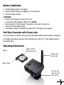
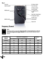
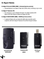
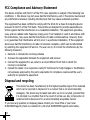
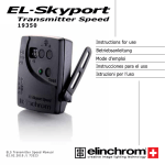
Transmitter Speed 19350 Instructions for use Betriebsanleitung Mode d’emploi Instrucciones para el uso Istruzioni per l’uso E L S Tr a n s m i t t e r S p e e d M a n u a l 02.02.2010 // 73323 English 1 - 10 Deutsch 11 - 20 Français 21 - 30 Español 31 - 40 Italiano 41 - 50 Guarantee 51- 54 English EL-Skyport Transmitter Speed 19350 Contents : Features 2 Battery Installation 3 Hot-shoe connector 3 Operating Instructions 3 Frequency Channel 4 Trigger Modes 5 Integrated SYNC Socket 6 Elinchrom RX Features 6 EL-Skyport Modules 8 Troubleshooting 9 CE Statements 9 FCC Compliance and Advisory Statement 10 Disposal and recycling 10 EL-Skyport Transmitter SPEED//19350 Operating instructions : 2.4 GHz digital wireless Flash Trigger Transmitter Features EL-Skyport Transmitter Speed is designed with the latest 2.4 GHz Digital Wireless Technology. • SLR Camera Sync speeds: SPEED mode up to 1/250 s, STANDARD mode 1/160 - 1/200 s. • 5 selectable trigger modes, (4 Groups + All) • 8 frequency channels. • 40 Bit security encryption. • Up to 60 m range indoors for standard mode and up to 40 m in speed mode. • Up to 120 m range outdoors for standard mode and up to 60 m in speed mode. • Battery life up to 6 Months - over 30’000 flashes. • RX-feature buttons (Remote Control). • Test trigger button and feature button. • Integrated Hot-shoe (middle contact) improved. • SYNC-socket for direct connection improved. • Two flash modes, standard and speed. • The “Standard” mode is full compatible with previous EL-Skyport versions. • The SPEED function is available for Ranger Quadra AS, BXRi 250 / 500 und D-Lite it and all other units, when used with the Universal Speed. • Status LED for EL-Skyport mode and battery status. • Improved housing, battery drawer and switches. • New Hot-shoe with screw-lock. • New extra features; configure EL-Skyport with the new EL-Skyport PC / MAC software 3.0. You will appreciate the convenience of this professional and powerful wireless device. Note: Shutter speed and distance range are influenced by interference from other 2.4 GHz electronic equipment and reflections of ceilings, walls, floors, furniture, metall, trees and humidiy in woods etc. For best performance the Transmitter and Receiver antenna should have direct sight, without any walls or objects in - between. 2 Battery Installation 1. Pull the battery drawer out carefully. 2. Place the Lithium battery, see Fig. 1 for correct polarity. 3. Close the battery drawer. ! CAUTION: • Ensure correct polarity / minus pole on top. • Use only the Lithium Battery CR2430 3.0 V 19372. • Remove battery if the EL-Skyport Transmitter is not used for some time. • Never short-circuit battery poles. • Avoid direct sunlight or temperatures above 45°C. The battery may explode! Hot-Shoe Connector with Screw-Lock The new Hot-shoe connector with screw-lock and middle contact synchronisation is designed to fit digital and analogue cameras with maximum sync output of 3 V (the middle contact is the positive pole). Operating Instructions Fig. 1 Battery (19372) Minus pole on top Flexible swivel Antenna 360 ̊ Battery drawer Hot-shoe with screw lock and SYNC socket 3 Fig. 2 Frequency channel selector RX feature button Power decrease MODE switch RX feature button Power increase or modelling lamp toggle Flash Test / Flash Mode / Configuration button Flexible swivel Antenna 360 ̊ GROUP switch Status LED Frequency Channel Note: Transmitter and the corresponding Transceiver RX, the Universal Receiver or the EL units with integrated EL-Skyport Receiver must have the same frequency channel settings! Frequency Channel 4 1 (default) 2 1 Off On Slide Button configuration 2 Off Off 3 Off Off Frequency / Mhz 3 4 5 Off On Off On On Off Off Off On 2460 2462 2469 6 7 8 On Off On Off On On On On On 2471 2473 2475 2456 2458 EL-Skyport Sync Speed & Standard Mode The SPEED function is available for Ranger Quadra AS, BXRi 250 / 500 und D-Lite it and all other units, when used with the EL-Skyport Universal Speed. Select “Speed” sync mode Synchronises SLR cameras up to 1/250 s, or compact digital cameras up to 1/2850 s, depending on the camera type & the flash duration of the flash unit. - Select “Group” or “All” mode. - Press test push button for minimum 5 seconds until the STATUS LED flashes two times. - Release test push button. - Now the EL-Skyport Transmitter Speed works in “SPEED” mode (r.2 mode). Select “Standard” triggering mode Synchronises SLR cameras up to 1/200 s, or compact digital cameras up to 1/1600 s, depending on the camera type & the flash duration of the flash unit. - Select “Group” or “All” mode. - Press test push button for minimum 5 seconds until the STATUS LED flashes one time. - Release test push button. - Now the EL-Skyport Transmitter Speed works in “STANDARD” mode. EL-Skyport Module Configuration: Only possible with EL-Skyport PC / MAC software v 3.0 and higher. - Power-Save Timer, individual programmable or disabled. - Trigger delay is programmable from 250 ms up to 15 s. - Download the FREE EL-Skyport Software from www.elinchrom.com SET Config Mode: (to configure included features) - Switch module OFF. - Hold test push button and switch TX ON. - Keep test push button pressed until STATUS LED is ON. Check also EL-Skyport PC / MAC software 3.0 for changing Transmitter Speed setting. 5 The EL-Skyport Transmitter triggers the EL-Skyport Receiver modules in the following modes: 1. Off Unit is OFF, no function. 2. Select Group - Group (1 to 4). Set switch to Group. and select Group 1 to 4. All corresponding EL-Skyport Receivers with the same selected Group (1 to 4) are triggered. 3. ALL Mode switch is set to ALL. All corresponding EL-Skyport Receivers are triggered regardless of which Group is selected. Integrated Hot-Shoe SYNC 2.5 mm Socket Use the included Sync cable to connect the integrated 2.5 mm Mono Jack socket with the camera or lens PC socket directly. EL-Skyport Transmitter SPEED RX Features Compatible with Ranger RX, Style RX, Digital RX, BXRi 250 / 500, Ranger Quadra AS! If the EL-Skyport Transmitter SPEED is used with the EL-Skyport Transceiver RX, BXRi 250 / 500 or the Ranger Quadra AS, the following EXTRA features are available: Depending upon which Group is selected, the following RX-unit settings can be modified: 1. Flash power increase in 1/10 f-stops. press push button + to increase the power of selected Group of (or ALL) RX-units in 1/10 f-stops. 2. Flash power decrease in 1/10 f-stops. press push button - to reduce the power of selected Group of (or ALL) RX-units in 1/10 f-stops. 3. Modelling lamp toggle. press and hold the push button +, 2 seconds or longer before releasing, to toggle modelling lamp of the selected Group of (or ALL) RX-units. 6 Power save mode timer: - After not using the Transmitter for 30 minutes the Power Save mode is active. To reactivate the Transmitter, press the TEST push button. - The Power Save mode timer can be configured with the EL-Skyport PC / MAC software v 3.0 and higher. Status LED: - LED flashes every 4 seconds one time in “Standard” mode and two times in “Speed” mode. - LED intensity correspond to the battery status - if off or very low => exchange the battery. - LED is OFF if the Transmitter is switched OFF or in Power Save mode. Reset to manufacturer default setting: - Switch ON. - Press test button for min 10 seconds. 7 EL-Skyport Modules EL-Skyport Universal SPEED (NEW) / Universal (previous version) • Universal Receiver for all makes of Flash with a SYNC socket, conforming to Sync norms! EL-Skyport Transceiver RX • This Transceiver is only for Elinchrom RX units. The module operates all RX features with the EL-Skyport software and triggers the flash. EL-Skyport USB RX SPEED (NEW) / USB RX (previous version) • To operate RX flash units via computer the USB module should be used in conjunction with the EL-Skyport Transceiver RX and the EL-Skyport software. Universal Speed & Universal 8 Transceiver RX 19353 USB RX Speed & USB RX Troubleshooting Should an error occur, first check the following points: Having this problem? Check the following points: No flash unit can be triggered with the Transmitter Mode “All” is selected Some units do not fire when triggered with the Transmitter Mode “Grp” is selected Check if the Channel selector switch is set to the same Group. Reduce distance to any “not working” unit. Check if Transmitter is in the same trigger mode Speed / Standard. TEST flash works, but the camera will not trigger flash unit Check hot-shoe fitting. Connect the 2.5 mm to PC SYNC cable instead of hot-shoe connection. Limited Distance range Check if the Transmitter is switched ON. Check battery polarity. Check if the Receiver module is connected correctly to the unit. Check if the frequency selector switch is set to the same channel. Check if Transmitter is in the same trigger mode Speed or Standard. Reposition the units. Increase the distance to walls and ceilings. Position the antenna of Transmitter and Receiver. Use an RX extension cable to reduce the distance between the modules. CE Statements This device has been tested and found to comply with the requirements set up in the council directive on the approximation of the law of member states relating to EMC Directive 89/336/EEC, Low Voltage Directive 73/23/EEC and R&TTE Directive 99/5/EC 9 FCC Compliance and Advisory Statement This device complies with Part 15 of the FCC rules. Operation is subject of the following two conditions: 1. this device may not cause harmful interference, and 2. this device must accept any interference received, including interferences that may cause undesired operation. The equipment has been certified to comply with the limits for a Class B computing device pursuant to Part 15 of the FCC Rules. These limits are designed to provide reasonable protection against harmful interference in a residential installation. This equipment generates, uses, and can radiate radio frequency energy and, if not installed or used in accordance with the instructions, may cause harmful interference to radio communications. However, there is no guarantee that interference will not occur in a particular installation. If this equipment does cause harmful interference to radio or television reception, which can be determined by switching the equipment off and on. The user can try to correct the interference by the following measures: 1. Reorient or relocate the receiving antenna 2. Increase the separation between the equipment and receiver 3. Connect the equipment to an outlet on a circuit different from that to which the receiver is connected. 4. Consult the dealer or an experience radio/TV technician for help Changes or modification not expressly approved by the party responsible for compliance could avoid the user’s authority to operate the equipment. Disposal and recycling This device has been manufactured to the highest possible degree from materials which can be recycled or disposed of in a manner that is not environmentally damaging. The device may be taken back after use to be recycled, provided that it is returned in a condition that is the result of normal use. Any components not reclaimed will be disposed of in an environmentally acceptable manner. If you have any question on disposal, please contact your local office or your local ELINCHROM agent (check our website for a list of all ELINCRHOM agents world wide). 10