1
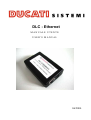
DLC - Ethernet
MANUALE UTENTE
USER'S MANUAL
06/2004
DLC-Ethernet/Rs485
DUCATI SISTEMI S.p.A.
INDEX
1.
Introduction.............................................................................................................1
2.
Converter Description .............................................................................................2
3.
4.
5.
2.1
Ethernet connector ................................................................................................................... 3
2.2
Power supply connector........................................................................................................... 3
2.3
Serial Rs485 connector ............................................................................................................ 4
Device Setup and configuration..............................................................................5
3.1
Factory default ......................................................................................................................... 5
3.2
How to modify the configuration............................................................................................. 5
DUCATI analyzers network applications ...............................................................6
4.1
Elements in a DUCATI Network............................................................................................. 6
4.2
DUCATI Network cabling....................................................................................................... 7
TECHNICAL CHARACTERISTICS.....................................................................8
5.1
Power Supply........................................................................................................................... 8
5.2
Operating Conditions............................................................................................................... 8
5.3
Weight and dimension ............................................................................................................. 9
5.4
Connectors ............................................................................................................................... 9
5.5
Reference Standards ................................................................................................................ 9
o --------------------------- o
Table of Figure
Figure 1: DLC-Ethernet Ducati appearance ...................................................................................2
Figure 2: RJ45 connector– front view..............................................................................................3
Figure 3: PSU supply connector .......................................................................................................3
Figure 4: Power supply table ............................................................................................................3
Figure 5: RS485 connector, DB9 – Male..........................................................................................4
Figure 6: RS485 connector pins table ..............................................................................................4
Figure 7: Factory default configuration table .................................................................................5
Figure 8: RS485 Network up to 31 instruments..............................................................................7
Figure 9: RS485 Network with more than 31 instruments ............................................................7
i
DLC-Ethernet/Rs485
1.
DUCATI SISTEMI S.p.A.
Introduction
DUCATI Sistemi s.p.a., pursuing a program of increasing participation in the energy
measurements and energy saving field, has developed a data converter Ethernet - RS485 which can
be used with all DUCATI analyzers provided with RS485 line interface. This converter allow
connecting a single instrument or a group of instruments (all of them connected each other through
the RS485 line) to an Ethernet port of a LAN, by TCP/IP protocol.
The RS485 serial line that links the DLC-Ethernet with the DUCATI instrument can be up to
1000 meters length or connect up to 31 instruments max. To obtain this performance the cable
should be a Belden 9841 type shielded two-wire cable. To overtake these limits, a "Signal
Repeater" DUCATI-SRD (article code 468001021) can be used: this allow to connect another 31
instruments group or 1000 meters of cable.
The Ethernet interface is a standard 10BaseT and can be connected to every standard plug of a
LAN, provided a check on the IP address. Every device on the network must have a unique IP
address and more devices can be connected to the LAN provided they have all different addresses
each other.
The main characteristics of the DLC-Ethernet converter are the following:
•
complete transparency to the user's software
•
bi-directional data flow
•
programmable baud rate on RS485 line, preset to the standard value of 9600 bps no Parity
•
suppression of transient disturbances from the RS485 serial line
•
integrated Line Terminator resistor for RS485
•
coverage up to about 1000 meters or 31 instruments on RS485 line
•
10BaseT Ethernet connection
•
Host connection via TCP/IP Protocol
•
Leds for Ethernet link and activity indication
•
Web interface for setup parameters programming
•
Password and Username for setup data protection
•
Total integration with DUCATI "WarpNet" Software (article code 468001078) where you
just need to setup the IP address of the converter / converters installed.
1
DLC-Ethernet/Rs485
2.
DUCATI SISTEMI S.p.A.
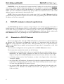
Converter Description
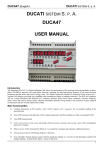
The DLC-Ethernet signal converter can easily be placed and connected to any Ethernet
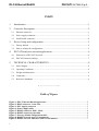
network and used in a network for analyzers data collection (LAN cable not included). It is housed
in a sturdy black ABS container as illustrated in the figure below:
Figure 1: DLC-Ethernet Ducati appearance
Device description:
2
•
On the right side there are two LEDs; one for signaling the Ethernet network Link and
the other for signaling Ethernet network Activity
•
Still on the right side it is available the Ethernet RJ45 plug (see Figure 2).
•
On the same side there is the jack for power supply (AC–Adapter 230Vac–9Vdc –
included) (see Figure 3)
•
Beside the power supply jack, it is accessible a small button for DHCP feature. It is
suggested not to use this function, but for more information on this feature please contact
our customer service at "supporto_analizzatori @ ducatisistemi.com".
•
On the left side is accessible the DB-9 shell connector for connecting the RS485 line to
the Ducati analyzers (see Figure 5). Included in the package is an interface D-shell
connector with some cable, for easy accessing the A,G,B wires for RS485.
DLC-Ethernet/Rs485
2.1
DUCATI SISTEMI S.p.A.
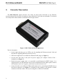
Ethernet connector
Pin2: Tx-
Pin3: Rx+
Pin1: Tx+
Pin6: Rx-
Figure 2: RJ45 connector– front view
2.2
Power supply connector
Figure 3: PSU supply connector
The positive pin (+) is connected with the internal contact, and the negative (-) is connect with
the external contact.
Power supply
Voltage
+ 7,5 ÷ + 9,0 Vdc
Max Consumption
145 mA
Connector type
5,5 x 2,1 mm
Figure 4: Power supply table
3
DLC-Ethernet/Rs485
2.3
DUCATI SISTEMI S.p.A.
Serial Rs485 connector
5
4
9
3
8
2
7
1
6
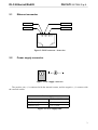
Figure 5: RS485 connector, DB9 – Male
Noninverting Receiver Input and
Noninverting Driver Output
Pin 1
A (+)
Pin 2
n.c.
Pin 3
n.c.
Pin 4
n.c.
Pin 5
GND
Ground
Pin 6
B (-)
Inverting Receiver Input and
Inverting Driver Output
Pin 7
n.c.
Pin 8
n.c.
Pin 9
n.c.
Figure 6: RS485 connector pins table
NOTE: in the package it is included a pre-assembled cable with a connector DB9 female for
easy RS485 connection.
4
DLC-Ethernet/Rs485
3.
3.1
DUCATI SISTEMI S.p.A.
Device Setup and configuration
Factory default
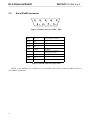
When purchased, if there aren’t any particular requests, the device will have the following
default setting.
Factory default
Password:
“ducati” (all in lower case)
Username
(none / blank)
IP address
192.168.5.245
Subnet mask
255.255.255.0
Host port
2000
Serial Rs485
9600 bps, no parity, 1 start bit, 1 stop bit
Last character
03h (etx)
Figure 7: Factory default configuration table
3.2
How to modify the configuration
Any LAN is characterized by a range of IP address that will be used. Our DLC-Ethernet is
preset with the IP address =192.168.5.245. If on the network is present another device with the
same IP, this one should be changed to avoid conflicts, otherwise you may modify the
DLC-Ethernet configuration in the following way.
Before starting with the setup, you need to configure a PC with IP address = 192.168.5.xxx with
xxx different from 245 and Subnet Mask = 255.255.255.0.
Now is possible to connect the DLC-Ethernet directly to the PC using a crossed network cable
(LAN cables not included) or it is possible (better) to use a HUB with a direct network cable (LAN
cables not included).
After the cable connection, the device can be programmed using a browser (Internet Explorer)
at 192.168.5.245 (http://192.168.5.245). A page will be visualized and the password requested: use
blank as Username and “ducati” (in lowercase) as Password. Follow the on-screen instructionsi in
the English language.
i
For particular cases it is possible to request a custom preset at the order.
5
DLC-Ethernet/Rs485
DUCATI SISTEMI S.p.A.
WARNING: in case the password is forgotten and the IP address is lost, the device can not be
reset to the factory default configuration by the user, and should be sent back to DUCATI for
service. However in order to recover the IP address it is possible to reconfigure the device with a
DHCP (for more information in DHCP usage please contact our customer service at the e-mail
address "supporto_analizzatori @ ducatisistemi.com".
NOTE: if there are more than one device on the same LAN, every DLC-Ethernet should be
connected and programmed in sequence one after the other, programming each one with a different
IP address at every new connection.
4.
DUCATI analyzers network applications
The DLC–Ethernet allows to connect a single analyzer or an analyzers group connected in a
RS485 network, to a PC through a LAN. It’s even possible to connect more DLC-Ethernet devices
in the same LAN. For example if in a shed there are one o more group of instruments, you may
connect them via RS485 in groups, and use one DLC-Ethernet for each group; finally connect each
DLC-Ethernet to the LAN, just taking care to use a different IP for each converter.
4.1
Elements in a DUCATI Network
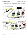
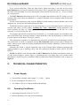
The next two figures show networks of DUCATI analyzers connected to a personal computer by
an Ethernet LAN. The former (see Figure 8) is with up to 31 instruments, while the latter (see
Figure 9) is the architecture with more units, which prescribes the use of "Signal Repeaters"
(SRDs) on the RS485 line to amplify and re-generate the signal after 31 instruments or after 1000
meters of cable.
Note that such a configuration can be reproduced for each DLC-Ethernet on the net.
The elements that constitute the network are the following:
• a shielded two-wire Belden 9841 cable (to be installed by the user) which includes wire A,
illustrated in the figures below, connected to clamp A of the serial port of the Ducati
analyzers and pin A of the DLC-Ethernet converter (and, of course, the same for wire B);
• a 120 ohm resistor used as Line Terminator, as show in the figures below in the frame
"Dettaglio" (detail);
• one or more DUCATI analyzers, all connected via the above mentioned Belden cable, up to
a maximum of 98 units (for each converter), if the Ducati-ASCII protocol is used, or up to
247 units if the MODBUS-RTU protocol is used;
• one or more SRD Signal Repeaters (available from Ducati Sistemi SpA with order code
468001021) to be installed in the RS485 network after each group of 31 analyzers or
1000 mt of cable;
6
DLC-Ethernet/Rs485
DUCATI SISTEMI S.p.A.
• the WapNet Software V2.6 or above. (available from Ducati Sistemi SpA with order code
468001078)ii. For this software it is required a Personal Computer P III a 400 MHz or
higher, Memory 128 Mb ram, Drive 20 GB, and Microsoft operating system.
4.2
DUCATI Network cabling
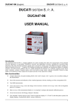
A (+) – Pin 1
DUCATI instruments
GND – Pin 5
DLC-Ethernet
B (-) – Pin 6
Belden cable 9841
A
A
A
B
B
B
G
G
G
Figure 8: RS485 Network up to 31 instruments
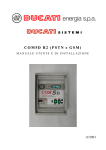
A (+) – Pin 1
DUCATI instruments
GND – Pin 5
DLC-Ethernet
B (-) – Pin 6
SRD DUCATI
Belden cable 9841
A
Ethernet
A
B
A
B
B
G
G
G
Figure 9: RS485 Network with more than 31 instruments
ii
The WarpNet software uses the ASCII-Ducati protocol, so allowing a maximum of 98 instruments each DLC-Ethernet
converter. For information, the software supports a mix of DLC–RS232 and DLC–Ethernet converters installed at the
same time.
7
DLC-Ethernet/Rs485
DUCATI SISTEMI S.p.A.
For a correct connection, follow the hints below; please note there is no limit on how many
DLC-Ethernet devices can be installed on the same LAN, a part from the limit on the total device
the LAN itself can handle. For more information refer to the NOTE at section 3.2 - "How to modify
the configuration".
The DLC-Ethernet connection to the LAN is possible either directly to the PC, using a crossed
network cable (LAN cable not included), or using a HUB with a direct network cable (LAN cable
not included).
For the connection between the converter RS485 D-shell connector and the Belden cable of the
analyzers net, you can use the included prepared cable.
The RS485 network connection is of multi-drop type, so every instrument must be connected in
cascade each other ("in-out" mode), avoiding any "star" connection, paying attention to the
correct polarity: all Pins “A” must be connected together and connected to the Pin "A" of the
converter, as well as for the Pin “B”.
To complete the network, insert the Line Terminator, i.e. a 120ohm resistor (not included) at the
end of the RS485 line, between terminal A and terminal B of the last instrument, as shown in the
previous figures, in the frame "Dettaglio" (detail).
The instrument's terminal G is connected to the electronic ground of each one through a resistor.
The connection of all the G terminals and the DLC-Ethernet signal ground (Pin 5) through the
cable's shield, can be used for keeping equilibrated all the reference potentials. In this case avoid
earth connections.
Normally the shield is instead connected only to the Ground Earth (without connecting the
signal grounds) to get a shielding effect, and this connection should be made ONLY IN ONE
POINT.
NOTE: the RS485 serial line that links the DLC-Ethernet to the Ducati instruments can be up
to 1000 meters length or connect up to 31 instruments max. For longer lines or to connect more
instruments, a Signal Repeater (amplifier) SRD (available from Ducati) should be used, as shown in
Figure 9.
5.
TECHNICAL CHARACTERISTICS
5.1
Power Supply
• External Power Supply with voltage 7,5 ÷ 9Vdc / 145mA
• Power consumption: less than 2 VA
• AC-adapter 230Vac to 9Vdc included in the package
5.2
Operating Conditions
• Operating temperature: from 5°C to 55°C
• Relative humidity: 90% max (non-condensing)
8
DLC-Ethernet/Rs485
DUCATI SISTEMI S.p.A.
• Protection Class IP20
• Mechanical resistance EN/IEC 61131-2
• Humidity Class F DIN 40040
5.3
Weight and dimension
• Module 98 x 24 x 57 mm
• Weigh 67g
5.4
Connectors
• Ethernet: IEEE 802.3 10BaseT RJ45
• Rs485: DB9 male (adapting cable included)
• Power supply: PSU Plug 5,5 x 2,1 mm
5.5
Reference Standards
• Compliant to the following EC directive:
• Electro Magnetic Compatibility - EC directive EMC 89/336/CEE
• Emission EN50022
• Immunity EN61000-6-2
• Electrical safety EN60950
9
DLC-Ethernet/Rs485
DUCATI SISTEMI S.p.A.
DUCATI Sistemi S. p. A. denies any responsibility for damage or personal injury caused by
the improper or erroneous use of this equipment.
This documentation may be subject to modification without prior notice.
Documentation code: DLC_Eth_ENG_V10.doc – Version 1.0 – June 2004.
Via Ronzani 47, - 40033 Casalecchio di Reno (Bologna) - Italy
Tel.: +39- 051 6116.611 - Fax: +39-051 6116.690
WEB: www.ducatisistemi. com
e-mail (Commerc.) = [email protected] // e-mail (Technical) = [email protected]
10