1
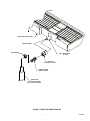
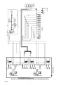
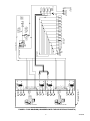
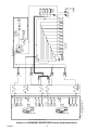
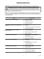
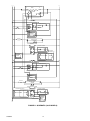
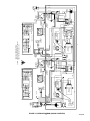
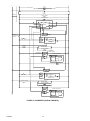
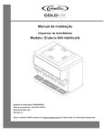
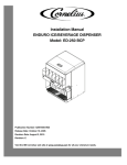
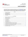
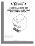
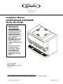
IMI CORNELIUS INC
www.cornelius.com
Installation Manual
ICE/BEVERAGE DISPENSER
Model: ED 300 BC
IMPORTANT:
TO THE INSTALLER.
It is the responsibility of
the Installer to ensure that
the water supply to the
dispensing equipment is
provided with protection
against backflow by an air
gap as defined in
ANSI/ASME A112.1.2-1979;
or an approved vacuum
breaker or other such
method as proved effective
by test.
Water pipe connections
and fixtures directly
connected to a potable
water supply shall be
sized, installed, and
maintained according to
Federal, State, and Local
Codes.
Part No. 92166INS
March 25, 2004
Revised: September 20, 2006
Revision: C
THIS DOCUMENT CONTAINS IMPORTANT INFORMATION
This Manual must be read and understood before installing or operating this equipment
© IMI CORNELIUS INC; 2004
PRINTED IN U.S.A
TABLE OF CONTENTS
Page
SAFETY PRECAUTIONS . . . . . . . . . . . . . . . . . . . . . . . . . . . . . . . . . . . . . . . . . . . . . . . . . . . . . . . . . . . . . . . . .
1
DESCRIPTION . . . . . . . . . . . . . . . . . . . . . . . . . . . . . . . . . . . . . . . . . . . . . . . . . . . . . . . . . . . . . . . . . . . . . .
1
SPECIFICATIONS . . . . . . . . . . . . . . . . . . . . . . . . . . . . . . . . . . . . . . . . . . . . . . . . . . . . . . . . . . . . . . . . . . .
1
INSTALLATION INSTRUCTIONS . . . . . . . . . . . . . . . . . . . . . . . . . . . . . . . . . . . . . . . . . . . . . . . . . . . . . . . . . .
2
GATE RESTRICTOR PLATE . . . . . . . . . . . . . . . . . . . . . . . . . . . . . . . . . . . . . . . . . . . . . . . . . . . . . . . . . .
4
ADJUSTMENT . . . . . . . . . . . . . . . . . . . . . . . . . . . . . . . . . . . . . . . . . . . . . . . . . . . . . . . . . . . . . . . . . . . . . .
4
REMOVAL AND REPLACEMENT OF AGITATORS . . . . . . . . . . . . . . . . . . . . . . . . . . . . . . . . . . . . . . .
6
TO REMOVE AGITATORS FOR CLEANING . . . . . . . . . . . . . . . . . . . . . . . . . . . . . . . . . . . . . . . .
6
TROUBLESHOOTING . . . . . . . . . . . . . . . . . . . . . . . . . . . . . . . . . . . . . . . . . . . . . . . . . . . . . . . . . . . . . . . . . . . .
11
BLOWN FUSE OR CIRCUIT BREAKER. . . . . . . . . . . . . . . . . . . . . . . . . . . . . . . . . . . . . . . . . . . . . . . . .
11
GATE DOES NOT OPEN. AGITATOR DOES NOT TURN. . . . . . . . . . . . . . . . . . . . . . . . . . . . . . . . .
11
GATE DOES NOT OPEN OR IS SLUGGISH. AGITATOR TURNS. . . . . . . . . . . . . . . . . . . . . . . . .
11
ICE DISPENSES CONTINUOUSLY. . . . . . . . . . . . . . . . . . . . . . . . . . . . . . . . . . . . . . . . . . . . . . . . . . . . .
11
SLUSHY ICE. WATER IN HOPPER. . . . . . . . . . . . . . . . . . . . . . . . . . . . . . . . . . . . . . . . . . . . . . . . . . . .
11
BEVERAGES DO NOT DISPENSE. . . . . . . . . . . . . . . . . . . . . . . . . . . . . . . . . . . . . . . . . . . . . . . . . . . . .
11
BEVERAGES TOO SWEET. . . . . . . . . . . . . . . . . . . . . . . . . . . . . . . . . . . . . . . . . . . . . . . . . . . . . . . . . . .
11
BEVERAGE NOT SWEET ENOUGH. . . . . . . . . . . . . . . . . . . . . . . . . . . . . . . . . . . . . . . . . . . . . . . . . . .
12
BEVERAGES NOT COLD (UNITS WITH BUILT–IN COLD PLATE). . . . . . . . . . . . . . . . . . . . . . . . .
12
AGITATORS TURN IN OPPOSITE DIRECTIONS . . . . . . . . . . . . . . . . . . . . . . . . . . . . . . . . . . . . . . . .
12
ICE DOES NOT DISPENSE FROM ONE GATE ASSEMBLY . . . . . . . . . . . . . . . . . . . . . . . . . . . . . .
12
WARRANTY . . . . . . . . . . . . . . . . . . . . . . . . . . . . . . . . . . . . . . . . . . . . . . . . . . . . . . . . . . . . . . . . . . . . . . . . . . . .
17
LIST OF FIGURES
FIGURE 1. DRIP TRAY DRAIN HOOK–UP . . . . . . . . . . . . . . . . . . . . . . . . . . . . . . . . . . . . . . . . . . . . . .
3
FIGURE 2. GATE RESTRICTOR PLATE . . . . . . . . . . . . . . . . . . . . . . . . . . . . . . . . . . . . . . . . . . . . . . . .
4
FIGURE 3. MOUNTING TEMPLATE (ICE ONLY –B MODELS) . . . . . . . . . . . . . . . . . . . . . . . . . . . .
4
FIGURE 4. MOUNTING TEMPLATE (–BC MODELS) . . . . . . . . . . . . . . . . . . . . . . . . . . . . . . . . . . . . .
5
FIGURE 5. AGITATORS REMOVAL AND REPLACEMENT . . . . . . . . . . . . . . . . . . . . . . . . . . . . . . . .
6
FIGURE 6. FLOW DIAGRAM (–BC MODELS WITH EIGHT BEVERAGE FAUCETS) . . . . . . . . .
7
FIGURE 7. FLOW DIAGRAM (–BC MODELS WITH TEN BEVERAGE FAUCETS) . . . . . . . . . . .
8
FIGURE 8. FLOW DIAGRAM (–BC MODELS WITH TWELVE BEVERAGE FAUCETS) . . . . . . .
9
FIGURE 9. FLOW DIAGRAM (–B MODELS WITH TWELVE BEVERAGE FAUCETS) . . . . . . . . .
10
FIGURE 10. WIRING DIAGRAM (120 V MODELS) . . . . . . . . . . . . . . . . . . . . . . . . . . . . . . . . . . . . . . .
13
FIGURE 11. SCHEMATIC (120 V MODELS) . . . . . . . . . . . . . . . . . . . . . . . . . . . . . . . . . . . . . . . . . . . . .
14
FIGURE 12. WIRING DIAGRAM (220/240 V MODELS) . . . . . . . . . . . . . . . . . . . . . . . . . . . . . . . . . . .
15
FIGURE 13. SCHEMATIC (220/240 V MODELS) . . . . . . . . . . . . . . . . . . . . . . . . . . . . . . . . . . . . . . . . .
16
FIGURE 14. FLOW DIAGRAM (–B MODELS WITH TWELVE BEVERAGE FAUCETS) . . . . . . .
17
i
92166INS
SAFETY PRECAUTIONS
Always: disconnect power to the dispenser before servicing or cleaning.
Never: place hands inside of hopper or gate area without disconnecting power to the dispenser. Agitator rotation occurs automatically when dispenser is energized!
This ice dispenser has been specifically designed to provide protection against personal injury and eliminates
contamination of ice. To insure continued protection and sanitation, observe the following:
ALWAYS: be sure the removable lid is properly installed to prevent unauthorized access to the hopper interior
and possible contamination of the ice.
ALWAYS: be sure the upper and lower front panels are securely fastened.
ALWAYS: keep area around the dispenser clean of ice cubes.
The drip tray can be easily and quickly removed. The unit must never be lifted or moved by the drip tray.
Dispenser cannot be used with crushed or flaked ice.
Use of bagged ice which has frozen into large chunks can void warranty. The
dispenser agitator is not designed to be an ice crusher. Use of large chunks of
ice which ”jam up” inside the hopper will cause failure of the agitator motor and
damage to the hopper. If bagged ice is used, it must be carefully and completely
broken into small, cube–sized pieces before filling into the dispenser hopper.
CAUTION:
DESCRIPTION
The ”ENDURO” series of ice dispensers solves your ice and beverage service needs in the sanitary, space
saving, economical way. Designed to be manually filled with ice from any remote ice making source, these
dispensers will dispense cubes (up to 1–1/4” in size), cubelets and hard–chipped or cracked ice; and, in addition, several flavors of post–mix beverages. ”BC” units include beverage faucets and a cold plate and are designed to be supplied direct from syrup tanks and carbonator, with no additional cooling required.
SPECIFICATIONS
Model Descriptions:
Ice Storage:
Maximum Number of Faucets Available:
Built-in Cold Plate:
ED300 (Ice only)
–B (Beverage Faucets)
–BC (Faucets andCold Plate)
–Z (No Drip Tray)
–F (Flavor Option)
300 lbs
12
Yes, on BC Models Only
Electrical:
120/1/60 Hz, 5.2 Amps Total Unit Draw
220–240 /1/50/60 Hz 4.0 Amps Total Unit Draw
Dimensions:
44-3/8 in. Wide X 31-1/2 in. Deep X 37 in. High
Z Model: 44-3/8 in. Wide X 23 1/16 in. Deep X 37 in. High
1
92166INS
INSTALLATION INSTRUCTIONS
1. Locate the dispenser indoors on a level counter top.
A.
LEG OPTION, Kit P/N 08017
Note: Before installing legs, the plastic plugs (6) in the base threaded holes must be removed.
Unpack the six (6) legs and install them into the threaded holes provided in the bottom of the unit. The
installer must provide flexibility in the product and utility supply lines to permit shifting the position of
the dispenser sufficiently to clean the area beneath it. For routing these lines above the countertop, a
support bracket is located under the unit base at the center from front to back.
B.
COUNTER MOUNTING
The ice dispenser must be sealed to the counter. The MOUNTING TEMPLATE (see applicable Figure
3 or 4) indicates where openings can be cut in the counter. Locate the desired position for the dispenser, then mark the outline dimensions on the counter using the template drawings. Cut openings in
counter.
Apply a continuous bead of National Sanitation Foundation (NSF) listed silastic sealant (Dow 732 or
equal) approximately 1/4” inside of the unit outline dimensions and around all openings. Then, position
the unit on the counter within the outline dimensions. All excess sealant must be wiped away
immediately. Bolt the dispenser to the counter with 3/8-16 bolts.
2. The beverage tubes, drain tube and power cord are routed through openings in the bottom of the unit. See
MOUNTING TEMPLATE (see applicable Figure 3 or 4), for locating the required clearance hole in the
counter for these utility lines.
3. DRIP TRAY DRAIN HOOKUP (see Figure 1): Route the drain tube to an open drain with the end of the tube
above the “flood level” of the drain. Use the tubing, fittings, and insulation provided with the Dispenser to
assemble the drain. The completed drain must pitch continuously downward and contain no “traps” or improper drainage will result.
Note: This equipment must be installed with adequate backflow protection to comply with applicable
Federal, State and Local codes.
4. Ice Only –B Models.
Connect the hopper drain tubes to an approved drain system with a backflow system with a backflow preventer in compliance to the local plumbing code. Do not “tee” into the drip tray drain line.
NOTE: All drain connections must be installed with adequate backflow protection to prevent contamination of the potable water supply and the ice storage hopper in accordance with Federal, State, and local
codes.
5. Connect the beverage system product tubes as indicated in the applicable Beverage System Schematic.
This work should be done by a qualified Service Person.
Note: See applicable Plumbing Schematic for the location of syrup and water connections
6. Attach drip tray assembly to the unit base using the three mounting pins provided. For –BC models, align
the cold plate drain elbows into the notches of the drip tray assembly.
7. Clean the hopper interior (see CLEANING INSTRUCTIONS in Owner’s Manual).
8. Connect the power cord to a 120 volt, 60 cycle, 3–wire grounded receptacle. For 220–240 V International
Units, a three-wire power cord is provided. An adapter plug for the particular country will need to be provided by the installer.
Note: Water pipe connections and fixtures directly connected to a potable water supply shall be sized,
installed and maintained according to Federal, State and Local Laws.
92166INS
2
REAR VIEW OF DRIP TRAY
SOLVENT BOND
HOSE CLAMP
DRIP TRAY DRAIN
FITTING
COUPLING
3/4 SOCKET X 3/4 FPT
BARB ADAPTER
1 BARB x 3/4 MPT
DRAIN LINE
1” I.D PLASTIC TUBING
(6 FT) WITH INSULATION
FIGURE 1. DRIP TRAY DRAIN HOOK–UP
3
92166INS
GATE RESTRICTOR PLATE
CAUTION: Disconnect power to dispenser before installing, removing or
adjusting restrictor.
FIGURE 2. GATE RESTRICTOR PLATE
ADJUSTMENT
This plate may be adjusted as shown in Figure 2 to reduce or increase with large containers the dispensing rate
of ice, especially desirable when using glasses or other containers with small openings. Adjustment can be
made by sliding up or down with nuts loosened, to obtain the desired amount of restriction.
44 3/8
1 13/16
1 5/16
40 3/4
20 3/8
4 TYP
1
14 TYP
4 1/2
OPENING
OPENING
21 1/4
18 5/8
23 1/16
29 3/4
31 1/2
–Z MODEL
7/16
(6) PLCS
OPENING (2) IN UNIT BASE FOR BEVERAGE
AND WATER MANIFOLD INLET LINES, HOPPER
DRAIN LINES (2), AND ELECTRICAL POWER
SUPPLY CORD.
REMOVABLE
DRIP TRAY
TO FRONT OF DRIP
TRAY ON COUNTER
TOP
TO FRONT TOP
OF DRIP TRAY
FIGURE 3. MOUNTING TEMPLATE (ICE ONLY –B MODELS)
92166INS
4
7/16 (6) PLACES
44 3/8
40 3/4
1 13/16
20 3/8
4 1/2
1 5/16
2 9/16
16 1/8
OPENING
12
18 5/8
21 1/4
23 1/16
15
29 3/4
31 1/2
Z MODEL
REMOVABLE
SINK
RECOMMENDED COUNTER OPENING SIZE
12” X 15” FOR UTILITIES AND
BEVERAGE TUBING. OPENING CAN BE
LOCATED ANYWHERE WITHIN THE SHADED
6 11/16
AREA.
8 5/8
15
3 1/2
22 3/8
TO FRONT OF DRIP
TRAY ON COUNTERTOP
TO FRONT TOP
3 3/16
OF DRIP TRAY
FIGURE 4. MOUNTING TEMPLATE (–BC MODELS)
5
92166INS
REMOVAL AND REPLACEMENT OF AGITATORS
RIGHT HAND AGITATOR
WITH HOLE IN UPRIGHT
LEFT HAND
AGITATOR
O–RING
COUNTERCLOCKWISE
CLOCKWISE
ROTATION
ROTATION
FRONT (VALVE SIDE) VIEW FROM TOP OF DISPENSER
FIGURE 5. AGITATORS REMOVAL AND REPLACEMENT
To Remove Agitators For Cleaning
(see Figure 5)
1. Lift agitator and disc from unit..
2. Remove O-Ring starting at notch. Warm the O-Ring with water to ease removal.
3. Lift the plastic agitator disc off of the stainless-steel agitator.
4. Replace by reversing steps.
Note: Refer to Sanitize Procedure in the Owners Instruction for complete cleaning and sanitizing
instructions.
92166INS
6
3
1
3
2
4
2
4
7
8
7
COLDPLATE
INLET
CONNECTIONS
6
5
FAUCETS
4
3
COLDPLATE
INLET
CONNECTIONS
2
1
FAUCETS
S3
S4
W3
W4
W1
W2
S2
S1
S8
S7
S6
S5
S8
S7
W3
W4
W1
W2
S5
S6
COLD PLATE
S4
S3
S2
S1
W1
W3
W4
W2
W1
W3
W4
W2
COLD PLATE
TO FLAVOR
MODULE OPTION
MODULE OPTION
TO FLAVOR
S7
SYRUP TANKS
15–50 PSIG
S8
S6
CARBONATOR
PUMP
CHECK
VALVE
OPTIONAL FOR
DIET DRINKS
OR ROOT BEER
5–15
PSIG
SYRUP INLETS
TO COLDPLATE
CARB WATER
NON–CARB WATER
S5
S4
S3
S2
INSTALL FOR
NON–CARB AS
REQUIRED
OPTIONAL
PRESSURE
REGULATOR
CO2
CYLINDER
PRESSURE
REGULATORS
S1
FILTER
POTABLE
WATER
SUPPLY
F1
F2
F3
FLAVOR
TANKS
25–30 PSIG
F4
FLAVOR MODULE OPTION
ITEM INSIDE BROKEN LINE
INCLUDED WITH UNIT
1
FLAVOR MODULE OPTION
FIGURE 6. FLOW DIAGRAM (–BC MODELS WITH EIGHT BEVERAGE FAUCETS)
FAUCETS VIEWED FROM THIS SIDE
92166INS
FLAVOR MODULE OPTION
8
1
3
4
2
4
FLAVOR MODULE OPTION
FAUCETS VIEWED FROM THIS SIDE
FIGURE 7. FLOW DIAGRAM (–BC MODELS WITH TEN BEVERAGE FAUCETS)
10
ITEM INSIDE BROKEN LINE
INCLUDED WITH UNIT
3
2
9
COLDPLATE
INLET
CONNECTIONS
8
7
6
FAUCETS
5
4
3
COLDPLATE
INLET
CONNECTIONS
2
1
FAUCETS
S10
S9
S8
S7
W1
W4
W3
S3
S4
S5
S1
S2
W2
W4
W3
S9
S10
S6
S7
S8
W2
W1
COLD PLATE
S6
S5
S4
S3
S2
S1
COLD PLATE
W3
W4
W2
W1
W3
W4
W2
W1
TO FLAVOR
MODULE OPTION
TO FLAVOR
MODULE OPTION
OPTIONAL FOR
DIET DRINKS
OR ROOT BEER
5–15 PSIG
TO COLDPLATE
SYRUP INLETS
CARB WATER
S10
S8
S7
SYRUP TANKS
15–50 PSIG
S9
CARBONATOR
PUMP
CHECK
VALVE
NON–CARB WATER
S6
S5
S4
S3
INSTALL FOR
NON–CARB AS
REQUIRED
OPTIONAL
PRESSURE
REGULATOR
S2
CO2
CYLINDER
PRESSURE
REGULATORS
S1
FILTER
POTABLE
WATER
SUPPLY
F1
F2
F3
FLAVOR
TANKS
25–30 PSIG
F4
92166INS
1
3
1
3
2
4
2
4
9
12
11
10
COLDPLATE
INLET
S9
S8
S7
S12
S11
S10
W1
W2
S9
S8
S7
S12
S11
S10
W3
W4
COLD PLATE
S6
S5
S4
CONNECTIONS
9
8
7
FAUCETS
6
5
4
S3
W1
W2
S3
S2
S1
S6
S5
S4
W3
W4
COLD PLATE
S1
S2
COLDPLATE
INLET
CONNECTIONS
3
2
1
FAUCETS
W3
W4
W2
W1
W3
W4
W2
W1
TO FLAVOR
MODULE OPTION
TO FLAVOR
MODULE OPTION
S10
S9
SYRUP TANKS
15–50 PSIG
S11
CARBONATOR
PUMP
CHECK
VALVE
OPTIONAL FOR
DIET DRINKS
OR ROOT BEER
5–15
S12
PSIG
TO COLDPLATE
SYRUP INLETS
CARB WATER
NON–CARB WATER
S8
S7
S6
S5
INSTALL FOR
NON–CARB AS
REQUIRED
OPTIONAL
PRESSURE
REGULATOR
S4
S3
FILTER
S2
FLAVOR
TANKS
25–30 PSIG
CO2
CYLINDER
PRESSURE
REGULATORS
S1
POTABLE
WATER
SUPPLY
F1
F2
F3
F4
FLAVOR MODULE OPTION
ITEM INSIDE BROKEN LINE
INCLUDED WITH UNIT
1
FLAVOR MODULE OPTION
FIGURE 8. FLOW DIAGRAM (–BC MODELS WITH TWELVE BEVERAGE FAUCETS)
FAUCETS VIEWED FROM THIS SIDE
92166INS
FLAVOR MODULE OPTION
10
1
3
4
2
4
FLAVOR MODULE OPTION
FAUCETS VIEWED FROM THIS SIDE
FIGURE 9. FLOW DIAGRAM (–B MODELS WITH TWELVE BEVERAGE FAUCETS)
12
S9
S8
S7
S6
S5
S4
S12
S11
S10
WATER
MANIFOLD
ITEM INSIDE BROKEN LINE
INCLUDED WITH UNIT
3
2
11
10
9
8
7
S3
S2
S1
WATER
MANIFOLD
FAUCETS
6
5
4
3
2
1
FAUCETS
CW2
CW1
CW2
CW1
TO FLAVOR
MODULE OPTION
MODULE OPTION
TO FLAVOR
REMOTE
REFRIGERATION
SYSTEM
TO S1 INLET
UNIT TYPICAL
NON–CARB WATER
OPTIONAL FOR
DIET DRINKS
OR ROOT BEER
5–15
PSIG
S12
SYSTEM
REFRIGERATION
TO REMOTE
S10
SYRUP TANKS
15–50 PSIG
S11
S9
CHECK
VALVE
CARBONATOR
PUMP
CARB WATER
S8
S7
S6
S5
INSTALL FOR
NON–CARB AS
REQUIRED
OPTIONAL
PRESSURE
REGULATOR
S4
S3
FILTER
S2
FLAVOR
TANKS
30 PSIG
CO2
CYLINDER
PRESSURE
REGULATORS
S1
POTABLE
WATER
SUPPLY
F1
F2
F3
F4
92166INS
1
TROUBLESHOOTING
IMPORTANT: Only qualified personnel should service internal components or electrical wiring.
WARNING: If repairs are to be made to a product system, remove quick disconnects from
the applicable product tank, then relieve the system pressure before proceeding. If repairs
are to be made to the CO2 system, stop dispensing, shut off the CO2 supply, then relieve the
system pressure before proceeding. If repairs are to be made to the refrigeration system, make sure
electrical power is disconnected from the unit.
Should your unit fail to operate properly, check that there is power to the unit and that the hopper contains ice. If the unit does not dispense, check the following chart under the appropriate symptoms to aid
in locating the defect.
Trouble
Probable Cause
BLOWN FUSE OR CIRCUIT BREAKER.
GATE DOES NOT OPEN. AGITATOR DOES NOT
TURN.
GATE DOES NOT OPEN OR IS SLUGGISH.
AGITATOR TURNS.
ICE DISPENSES CONTINUOUSLY.
SLUSHY ICE. WATER IN HOPPER.
BEVERAGES DO NOT DISPENSE.
BEVERAGES TOO SWEET.
11
A.
Short circuit in wiring.
B.
Defective gate solenoid.
C.
Defective agitator motor.
D.
Defective gate rectifier
A.
No power.
B.
Bent depressor plate (does not actuate switch).
C.
Defective dispensing switch.
A.
Defective gate solenoid.
B.
Excessive pressure against gate slide.
C.
Defective Rectifier.
A.
Stuck or bent depressor plate (does not
release switch).
B.
Defective dispensing switch.
C.
Improper switch installation.
A.
Blocked drain.
B.
Unit not level.
C.
Poor ice quality due to water quality or
icemaker problems.
D.
Improper use of flaked ice.
A.
No 24 volt power to faucets.
B.
No CO2 pressure.
A.
Carbonator not working.
B.
No CO2 pressure in carbonator.
C.
Faucet brix requires adjusting.
92166INS
Trouble
Probable Cause
A.
Empty syrup tank.
B.
Faucet brix requires adjusting.
BEVERAGES NOT COLD (UNITS WITH BUILT–IN
COLD PLATE).
A.
Unit standing with no ice in hopper – no ice in
cold plate cabinet.
AGITATORS TURN IN OPPOSITE DIRECTIONS
A.
This is normal and is necessary for uniform ice
agitation.
ICE DOES NOT DISPENSE FROM ONE GATE
ASSEMBLY
A.
Agitators reversed
B.
Defective gate solenoid or rectifier
C.
Motors wired incorrectly
A.
No 24 volt power to PC board.
B.
No CO2 pressure.
C.
Empty syrup tank.
D.
Kinked tubing.
E.
Clogged inner nozzle.
F.
Defective PC board.
G.
Defective harness from keypad.
H.
Defective Flow control.
I.
Defective solenoid harness.
J.
Defective keypad.
A.
Dip switch settings on control board incorrect.
B.
PC board defective.
C.
Defective flow control.
A.
Dip switch settings on control board incorrect.
B.
Flow control incorrectly set.
C.
PC board defective.
D.
Defective flow control.
BEVERAGE NOT SWEET ENOUGH.
FLAVOR SYRUPS DO NOT DISPENSE.
FLAVOR DISPENSES FOR MORE THAN 1 SEC.
FLAVOR DISPENSES MORE THAN .5 OZ.
Contact your local syrup or beverage equipment distributor for additional information and troubleshooting of beverage system.
92166INS
12
13
OPTIONAL
LIGHT
SOCKET
BLACK
WO B
HRL
I NA
T C
E K
B
L
U
E
GRN
B
L
U
E
MOTOR
CAPACITOR
BLACK
G
R
OPTIONAL
E
E LIGHT STARTER
N
B R
L E
U D
E
4
FLAVOR OPTION
LIGHT
2
BLUE
ICE LEVEL
SIGNAL OPTION
1
T’STAT
(WATER–5)
BLUE
RED
OPTIONAL
LIGHT
BALLAST
PINK
BLACK
WHITE
G
R
E
E
N
BLACK
GREEN/YELLOW
B
GATE
L
U
SOLENOID
E
(DC COIL)
TO 24V TRANSFORMER
TO HINGE BRACKET
ESD
BLACK
B
L
A
C
K
KEY
SWITCH
(OPTIONAL)
BLUE
WHITE
B
L
A
C
K
WHT
BLK
TO BEVERAGE
FAUCET
4
3
FLAVOR SOLENOIDS
B WG
L HR
AI E
CT E
KE N
3
GRN
2
W
H
I
T
E
WHITE
WHITE
W
H
I
T
E
WHITE
BLACK
R
E
D
B
L
A
C
K
OPTIONAL
LIGHT
SOCKET
B
L
U
E
ESD
OPTIONAL
LIGHT STARTER
BG
LR
UN
E/
Y
E
L
MOTOR
CAPACITOR
BLACK
RED
BLACK
WB O B R
H L RL E
I ANU D
TC E
EK
RIGHT
AGITATOR
MOTOR
(CW)
B
L
B A
L C
R A K
E C
D K
BLUE
BEVERAGE
TRANSFORMER
(OPTIONAL)
YELLOW
YELLOW
YELLOW
DISPENSE
SWITCH
MOTOR
HEATER
KEYPAD
4
KEYPAD
3
N
L
1
2
1
2
LEFT
AGITATOR
MOTOR
(CCW)
BLK
YEL
BLU
RED
BRN
WHT
POWER BEFORE SERVICING UNIT.
1
PCB BOARD
SERVICE INFORMATION
DANGER ELECTRIC SHOCK HAZARD. DISCONNECT
RED
BLACK
J10
WHITE
BLK
WHT
WHITE
RED
B
L
A
C
K
B
L
A
C
K
W
H
I
T
E
MOTOR
HEATER
W
H
I
T
E
WHITE
W
H
I
T
E
BLACK
R
E
D
W
H
I
T
E
B
L
A
C
K
OPTIONAL
LIGHT
SOCKET
WHITE
B
L
B A
L C
R A K
E C
D K
BEVERAGE
TRANSFORMER
(OPTIONAL)
YELLOW
YELLOW
YELLOW
DISPENSE
SWITCH
BLACK
TO BEVERAGE
FAUCET
4
3
2
1
KEY
SWITCH
(OPTIONAL)
WHITE
BLUE
BLACK
AGITATION
TIMER
NC NOCOM J9
L1
L2
BLACK
NC NOCOM
PINK
OPTIONAL
LIGHT
BALLAST
BLUE
BLUE
BLACK
BLUE
WHITE
BLACK
B
L
U
E
LIGHT
2
BLUE
ICE LEVEL
SIGNAL OPTION
1
T’STAT
(WATER–5)
BLK
YEL
BLU
RED
BRN
WHT
TO 24V TRANSFORMER
SOLENOID
(DC COIL)
GATE
FLAVOR OPTION
PCB BOARD
FLAVOR SOLENOIDS
FIGURE 10. WIRING DIAGRAM (120 V MODELS)
92166INS
G
L
N
TIMER
L1
L2
RECTIFIER
MOTOR HEATER
AGITATOR MOTOR
N.O.1
C
VEND SWITCH
N.C.1
CAPACITOR
GATE
SOLENOID
BALLAST
OPTIONAL LIGHT
STARTER
OPTIONAL
BEVERAGE TRANSFORMER
OPTIONAL ICE LEVEL
OPTIONAL
FLAVOR VLVS
OPTIONAL
BEVERAGE
VALVES
PCB
VLV
SOLENOIDS BOARD
KEYPAD
BEVERAGE PANEL
MOTOR HEATER
AGITATOR MOTOR
N.O.2
C
VEND SWITCH
N.C.2
CAPACITOR
GATE
SOLENOID
BALLAST
OPTIONAL LIGHT
STARTER
OPTIONAL
BEVERAGE TRANSFORMER
OPTIONAL FLAVOR VLVS
PCB
VLV
SOLENOIDS BOARD
OPTIONAL ICE LEVEL
KEYPAD
BEVERAGE PANEL
OPTIONAL
BEVERAGE
VALVES
FIGURE 11. SCHEMATIC (120 V MODELS)
92166INS
14
15
OPTIONAL
LIGHT
SOCKET
BLACK
BLACK
4
BLACK
BRN
2
BLUE
LIGHT
BLUE
RED
OPTIONAL
LIGHT
BALLAST
WHITE
G
R
E
E
N
PINK
B
L
A
C
K
BLUE
B
L
A
C
K
BRN
W
H
I
T
E
WHITE
WHITE
WHITE
BLACK
R
E
D
R
E
D
BEVERAGE
TRANSFORMER
(OPTIONAL)
YELLOW
YELLOW
RED
YELLOW
DISPENSE
SWITCH
WHT MOTOR
HEATER
BLK
TO BEVERAGE
FAUCET
4
KEY
SWITCH
(OPTIONAL)
ICE LEVEL
SIGNAL OPTION
1
T’STAT
(WATER–5)
B
L
U
E
TO 24V TRANSFORMER
FLAVOR OPTION
GATE
SOLENOID
(DC COIL)
MOTOR
CAPACITOR
G
R
OPTIONAL
E
E LIGHT STARTER
N
BB
LL
UU
EE
GRN
TO HINGE
ESD
3
2
1
FLAVOR SOLENOIDS
G
OB B R
BBR W
RL L E
RL E H
N U E IT N A
D
CU
E
N
E K
3
BLACK
WB O B R
H L RL E
I ANU D
TC E
EK
OPTIONAL
LIGHT
SOCKET
B
L
A
BC
L K
A
C
K
B
L
A
C
K
RIGHT
AGITATOR
MOTOR
(CW)
ESD
RED
MOTOR
CAPACITOR
BLACK
BLUE
TS
OPTIONAL
LIGHT STARTER
BB
L L
UU
EE
KEYPAD
4
GRN
2
3
N
L
1
2
KEYPAD
BLK
YEL
BLU
RED
BRN
WHT
POWER BEFORE SERVICING UNIT.
1
LEFT
AGITATOR
MOTOR
(CCW)
PCB BOARD
SERVICE INFORMATION
BLACK
RED
GATE
SOLENOID
(DC COIL)
AGITATION
TIMER
NC NOCOM J9
L1
BLUE
BLACK
BLACK
WHITE
BLACK
WHITE
L2
NC NOCOM J10
PINK
OPTIONAL
LIGHT
BALLAST
WHITE
BLK
B
L
A
C
K
RED
W
H
I
T
E
WHT
TO BEVERAGE
FAUCET
4
3
2
1
KEY
SWITCH
(OPTIONAL)
TO 24V TRANSFORMER
B
L
U
E
ICE LEVEL
SIGNAL OPTION
1
2
BLUE
T’STAT
LIGHT
BLK
YEL
BLU
RED
BRN
WHT
(WATER–5)
PCB BOARD
FLAVOR OPTION
DANGER ELECTRIC SHOCK HAZARD. DISCONNECT
FLAVOR SOLENOIDS
FIGURE 12. WIRING DIAGRAM (220/240 V MODELS)
92166INS
W
H
I
T
E
WHITE
W
H
I
T
E
BLACK
W
H
I
T
E
WHITE
B
L
B A
L C
A K
C
K
B
L
A
C
K
ON/OFF
SWITCH
OPTIONAL
LIGHT
SOCKET
BEVERAGE
TRANSFORMER
(OPTIONAL)
YELLOW
YELLOW
YELLOW
DISPENSE
SWITCH
MOTOR
HEATER
B
R
N
B
R
N
G
N
L
EMC
LINE
FILTER
E–BOX GD.
MOTOR HEATER
MOTOR HEATER
TIMER
L1
L2
RECTIFIER
GATE
SOLENOID
POWER
PUSH BUTTON
SWITCH
N.C1
C
VEND SWITCH
N.O1
AGITATOR MOTOR
OPTIONAL
BALLAST
OPTIONAL LIGHT
OPTIONAL STARTER
OPTIONAL
BEV. TRANSFORMER
BEVERAGE
KEYLOCK SWITCH
OPTIONAL FLAVOR VLVS
24V
PCB
VLV
SOLENOIDS
BOARD
BEV. FAUCETS
KEYPAD
EMC
GATE
SOLENOID
N.C2
C
VEND SWITCH
N.O2
OPTIONAL BALLAST
AGITATOR MOTOR
OPTIONAL LIGHT
OPTIONAL STARTER
OPTIONAL BEV. TRANSFORMER
OPTIONAL FLAVOR VLVS
24V
BEV. FAUCETS
PCB
VLV
SOLENOIDS BOARD
FIGURE 13. SCHEMATIC (220/240 V MODELS)
92166INS
16
KEYPAD
3
1
3
2
4
2
4
FLAVOR MODULE OPTION
17
1
2
3
4
5
6
FAUCETS
7
8
9
10
11
12
S1
S2
S3
S4
S5
S6
S7
S8
S9
S10
S11
S12
CW2
CW1
WATER
BEVERAGE LINES SHOWN IN
DIFFERENT LINE STYLES FOR
CLARITY
REMOTE
REFRIGERATION
SYSTEM
OPTIONAL FOR
DIET DRINKS
OR ROOT BEER
5–15
PSIG
S12
S10
S9
CHECK
VALVE
SYRUP TANKS
15–50 PSIG
S11
CARBONATOR
PUMP
NON–CARB WATER
CARB WATER
S8
S7
S6
S5
INSTALL FOR
NON–CARB AS
REQUIRED
OPTIONAL
PRESSURE
REGULATOR
S4
S3
TO FLAVOR
MODULE OPTION
TO FLAVOR
MODULE OPTION
FILTER
S2
POTABLE
WATER
SUPPLY
S1
CO2
CYLINDER
PRESSURE
REGULATORS
25–30
TANKS
FLAVOR
PSIG
F1
F2
F3
F4
FAUCETS
INCLUDED
ITEM INSIDE
WITHBROKEN
UNIT LINE
1
FLAVOR MODULE OPTION
FAUCETS VIEWED FROM THIS SIDE
FIGURE 14. FLOW DIAGRAM (–B MODELS WITH TWELVE BEVERAGE FAUCETS)
92166INS
WARRANTY
IMI Cornelius Inc. warrants that all equipment and parts are free from defects in material and workmanship under normal use and service. For a copy of the warranty applicable to your Cornelius product, in your country, please write, fax or telephone the IMI Cornelius office nearest you. Please
provide the equipment model number, serial number and the date of purchase.
IMI Cornelius Offices:
Locate the office in your area on the Cornelius web site, www.cornelius.com, under the contacts tab.
92166INS
18
IMI CORNELIUS INC.
92166INS
18