1
Instruction Manual
PN 51-430/rev.A
May 1996
Dissolved Oxygen Sensor
Model 430 DO
ESSENTIAL INSTRUCTIONS
READ THIS PAGE BEFORE PROCEEDING!
Rosemount Analytical designs, manufactures, and tests its products to
meet many national and international standards. Because these instruments are sophisticated technical products, you must properly install, use,
and maintain them to ensure they continue to operate within their normal
specifications. The following instructions must be adhered to and integrated
into your safety program when installing, using, and maintaining Rosemount
Analytical products. Failure to follow the proper instructions may cause any
one of the following situations to occur: Loss of life; personal injury; property damage; damage to this instrument; and warranty invalidation.
• Read all instructions prior to installing, operating, and servicing the product. If this Instruction Manual is not the correct manual, telephone 1-800654-7768 and the requested manual will be provided. Save this
Instruction Manual for future reference.
• If you do not understand any of the instructions, contact your Rosemount
representative for clarification.
• Follow all warnings, cautions, and instructions marked on and supplied
with the product.
• Inform and educate your personnel in the proper installation, operation,
and maintenance of the product.
• Install your equipment as specified in the Installation Instructions of the
appropriate Instruction Manual and per applicable local and national
codes. Connect all products to the proper electrical and pressure sources.
• To ensure proper performance, use qualified personnel to install, operate,
update, program, and maintain the product.
• When replacement parts are required, ensure that qualified people use
replacement parts specified by Rosemount. Unauthorized parts and procedures can affect the product’s performance and place the safe operation of your process at risk. Look alike substitutions may result in fire, electrical hazards, or improper operation.
• Ensure that all equipment doors are closed and protective covers are in
place, except when maintenance is being performed by qualified persons,
to prevent electrical shock and personal injury.
DANGER
HAZARDOUS AREA INSTALLATION
Installations near flammable liquids or in hazardous
area locations must be carefully evaluated by qualified on site safety personnel. This sensor is not
Intrinsically Safe or Explosion Proof.
To secure and maintain an intrinsically safe installation, the certified safety barrier, transmitter, and
sensor combination must be used. The installation system must comply with the governing
approval agency (FM, CSA or BASEEFA/CENELEC) hazardous area classification requirements. Consult your analyzer/transmitter instruction manual for details.
Proper installation, operation and servicing of this
sensor in a Hazardous Area Installation is entirely
the responsibility of the user.
CAUTION
SENSOR/PROCESS
APPLICATION COMPATIBILITY
The wetted sensor materials may not be
compatible with process composition
and operating conditions. Application
compatibility is entirely the responsibility of the user.
About This Document
This manual contains instructions for installation and operation of the Model 430 Dissolved Oxygen
Sensor. The following list provides notes concerning all revisions of this document.
Rev. Level
Date
A
5/96
Emerson Process Management
Liquid Division
2400 Barranca Parkway
Irvine, CA 92606 USA
Tel: (949) 757-8500
Fax: (949) 474-7250
http://www.raihome.com
© Rosemount Analytical Inc. 2003
Notes
This is the initial release of the product manual. The manual has been reformatted to reflect the Emerson documentation style and updated to reflect any
changes in the product offering.
MODEL 430 DO
TABLE OF CONTENTS
MODEL 430
DISSOLVED OXYGEN
TABLE OF CONTENTS
Section Title
Page
1.0
1.0
1.2
1.3
1.4
1.5
DESCRIPTION AND SPECIFICATIONS.................................................................
Features and Applications ......................................................................................
Operation ................................................................................................................
Available Models......................................................................................................
Specifications...........................................................................................................
Ordering Information ...............................................................................................
1
1
1
2
2
4
2.0
2.1
2.2
2.3
2.4
INSTALLATION .......................................................................................................
General ....................................................................................................................
Unpacking and Inspection ......................................................................................
Mechanical Installation ...........................................................................................
Electrical Installation ................................................................................................
5
5
5
5
5
3.0
3.1
3.2
MAINTENANCE ......................................................................................................
General ....................................................................................................................
Recharging the Sensor ............................................................................................
9
9
9
4.0
4.1
4.2
4.3
TROUBLESHOOTING.............................................................................................
General ....................................................................................................................
Troubleshooting .......................................................................................................
Bench Testing ..........................................................................................................
10
10
10
10
5.0
5.1
PARTS LIST ...........................................................................................................
General ....................................................................................................................
11
11
6.0
6.1
6.2
6.3
RETURN OF MATERIAL .........................................................................................
General ....................................................................................................................
Warranty Repair.......................................................................................................
Non Warranty Repair ...............................................................................................
15
15
15
15
i
MODEL 430 DO
TABLE OF CONTENTS
TABLE OF CONTENTS CONTINUED
LIST OF FIGURES
Number
1-1
1-2
2-1
2-2
5-1
5-2
5-3
5-4
Title
Page
Flow Through Senson Assemblies .........................................................................
Optional Mounting Bracket .....................................................................................
Code 01 and 02 Flow Through Installation ...........................................................
Sensor Dimensions ................................................................................................
Model 430 (Codes 01 and 02) Dissolved Oxygen Sensor .....................................
Model 430 Sensor Assembly ..................................................................................
Model 430 (Code 03) Dissolved Oxygen Sensor ...................................................
Model 430 (Code 04) Dissolved Oxygen Sensor....................................................
2
3
6
7
11
12
13
14
LIST OF TABLES
Number
2-1
Title
Page
Electrical Connections ...........................................................................................
ii
5
MODEL 430 DO
SECTION 1.0
DESCRIPTION AND SPECIFICATIONS
SECTION 1.0
GENERAL DESCRIPTION AND SPECIFICATIONS
•
LARGE ELECTROLYTE RESERVOIR allows up to twelve months and often longer
between refills.
•
OPTIONAL MOUNTING BRACKET allows easy removal of the sensor from an aeration
basin without the use of tools.
•
MODULAR PRESSURE COMPENSATOR AND MEMBRANE RETAINER simplify recharging and membrane replacement.
•
MEMBRANE RETAINER REPLACEMENT AND RECHARGING require no tools.
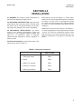
1.1 FEATURES AND APPLICATIONS
The Rosemount Analytical® Model 430 Dissolved
Oxygen Sensor, used with the Model 1181 Dissolved
Oxygen Transmitter, measures oxygen levels in a variety of applications. The most widely used application is
the secondary phase of the waste treatment process
where a critical dissolved oxygen level must be maintained for the digestive process to occur. Other applications include water quality monitoring in natural bodies of water such as rivers and streams, or any location
where adequate oxygen content is important to sustain
aquatic life.
The Model 430 Dissolved Oxygen Sensor is constructed of PVC with an oxygen permeable Teflon1 membrane .
1.2 OPERATION
As oxygen passes through the Teflon membrane an
oxygen dependent electrochemical reaction takes
place between the gold cathode and silver anode in the
presence of the electrolyte. The resultant current flow
between these elements is proportional to the quantity
of oxygen which has entered the sensor.
Temperature and pressure compensation are both
standard features on the Model 430. Temperature compensation is necessary for two reasons: First, the solubility of oxygen in water decreases with an increase in
temperature; secondly, the permeability of the Teflon
membrane and the oxygen diffusion rate increase as
the temperature increases. For these reasons, it is
important for a dissolved oxygen measurement to be
accompanied by an accurate temperature measurement. Temperature compensation is accomplished by
means of a thermistor located in the sensor housing,
and its associated circuitry in the analyzer.
Pressure compensation is a mechanical rather than
electronic correction. It is important for the tension on
the Teflon membrane to remain constant at all times,
even with sample pressure changes. Fluctuations in
membrane tension affect its diffusion characteristics.
By means of a pressure compensator the pressure on
the sample side of the compensator membrane is
transmitted to the electrolyte reservoir so the pressure
on both sides of the membrane remains equal. In this
manner, sample pressure changes do not affect the diffusion rate of oxygen through the membrane.
The Teflon membrane is held in place by a retainer. A
water-tight seal is made with an O-ring between the
membrane and sensor reservoir. Membrane replacement is rarely required, but in those situations when it
is necessary, the procedure can be performed quickly
and easily.
Since oxygen diffuses through the Teflon membrane at
a faster rate than through the sample, it is necessary to
continuously maintain a fresh sample in front of the
membrane. A stream velocity of approximately 1.5 feet
per second (0.5 m/s) is required to ensure that a fresh
sample is in contact with the membrane at all times.
1 Reg. U.S. Pat. Office for du Pont’s fluorocarbon resins.
1
MODEL 430 DO
SECTION 1.0
DESCRIPTION AND SPECIFICATIONS
1.3 AVAILABLE MODELS
The Model 430-01 and -02 Sensor is a flow through
assembly. The sensor is supplied in a 1-1/2 inch PVC
tee for installation into a process line.
The Model 430-03 Submersible Sensor is for use in
those applications where the required flow velocity can
be maintained without the use of an agitator. When the
measurement is being made in a stagnant pond or
other media where the minimum flow rate of 1.5 FPS
cannot be obtained, the Model 430-04 must be selected. This model is designed for submersible use and is
provided with its own agitator to ensure adequate flow
velocity at the membrane.
The Models 430-03 and 04 may be provided with an
optional mounting bracket assembly. This bracket is
constructed of light weight aluminum and can be
adjusted to satisfy virtually any aeration basin mounting requirement. Once installed, the probe can be
removed without the use of tools. A single locking pin
holds the assembly rigidly in place but allows it to be
easily removed for inspection or cleaning.
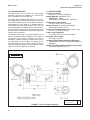
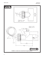
1.4 SPECIFICATIONS
Process Connection:
430-00/01 1-1/2 inch socket fitting
Wetted Materials: HOUSING - PVC
MEMBRANE - Teflon
PRESSURE COMPENSATOR - Neoprene
Temperature Compensation:
0 to 50°C (32 to 122°F) Automatic
Sample Pressure: 0-50 psig (345 kPa abs)
Submersible to 200 ft. (61 m).
Agitator Power Requirement: Model 430-04 only)
115 Vac, ±10 60 Hz (0.2 amp)
Cable Length (standard):
6.1 meters (20 ft) on sensor and agitator
Maximum Cable Length:
305 meters (1000 ft)
Operating Time Between Electrolyte Recharge:
Approximately 12 months or longer, depending upon
application
Sample Flow Requirements for Models 430-01-02-03:
1.5 feet per seconds (0.5 m/s)
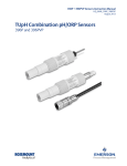
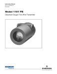
MILLIMETER
INCH
DWG. NO.
40043019
FIGURE 1-1 Flow Through Assemblies
2
REV.
A
MODEL 430 DO
SECTION 1.0
DESCRIPTION AND SPECIFICATIONS
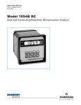
MILLIMETER
INCH
DWG. NO.
40043018
REV.
B
FIGURE 1-2 Optional Mounting Bracket
3
MODEL 430 DO
SECTION 1.0
DESCRIPTION AND SPECIFICATIONS
1.5 ORDERING INFORMATION. The Model 430 Dissolved Oxygen Sensor: Includes PVC body with integral,
oxygen-permeable membrane of Teflon1. Temperature and pressure compensators included. Compatible with
Model1181DO.
MODEL
430 DO
DISSOLVED OXYGEN SENSOR
CODE
01
02
03
04
MOUNTING HARDWARE
1-1/2” PVC flow cell, 90° flow
1-1/2” PVC flow cell, 180° flow
PVC union with 3/4” FNPT for submersion service
PVC union with 1” FNPT and agitator with 20 foot cable for submersion. Agitator motor requires
115 VAC power only.
CODE
11
14
15
17
MOUNTING HARDWARE
Stainless steel tag (specify marking)
Handrail mounting bracket (P/N 1000857) for use with junction box (see Code 17 below).
Handrail mounting bracket (P/N 1000856) for use with Model 803
Weatherproof, NEMA 4X junction box (P/N 22719-02)
499 DO
01
16
EXAMPLE
NOTES:
Recommended interconnecting cable from sensor to transmitter is Belden 8434 or equivalent, available from Rosemount Analytical as P/N
9200074. Specify length.
Reg. U.S. Pat. Office for du Pont's fluorocarbon resins.
1
4
MODEL 430 DO
SECTION 2.0
INSTALLATION
SECTION 2.0
INSTALLATION
2.1 GENERAL. This section provides instructions for
the Model 430 Dissolved Oxygen Sensor.
2.2 UNPACKING AND INSPECTION. Inspect the shipping container and remove the sensor. Carefully check
the sensor and its associated hardware for any damage. Report any damage to the carrier immediately.
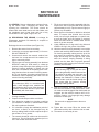
2.3 MECHANICAL INSTALLATION. The sensor
comes in four different configurations. Follow the
instruction for the configuration being installed. See
Figure 2-2 for dimensions. Figure 1-2 illustrates
optional bracket assembly for sensor installation in
tanks or ponds.
2.3.1 Codes 01 and 02 (see Figure 2-1). These configurations are for flow through measurements. Install the
tee using 1-1/2 inch PVC. For the angle flow (Code
01), make sure the flow enters at the opening opposite
the sensor, so that the sample flows directly into the
membrane.
2.3.2 Codes 03 and 04 (see Figure 5-3 and Figure 54). These configurations are for submersion into a tank
or pond. The Code 03 configuration requires a flow
past the sensor of 1.5 feet per second (0.5 m/s). The
Code 04 configuration is for stagnant or still tanks and
ponds.
2.4 Electrical Installation. Connect the sensor to the
transmitter as shown in Table 2-1.
TABLE 2-1 Electrode Connections
Sensor Lead
Model 1181DO
1. (Red) silver anode
TB2-4
2. Shield
TB2-2
3. (White) T.C. element
TB2-1
4. (Green) T.C. element
TB2-3
5. (Black) gold cathode
TB2-3
5
MODEL 430 DO
SECTION 2.0
INSTALLATION
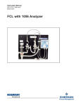
MILLIMETER
INCH
DWG. NO.
40043001
FIGURE 2-1. Codes and 01 and 02 Flow Through Installation
6
REV.
G
MODEL 430 DO
SECTION 2.0
INSTALLATION
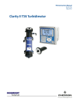
MILLIMETER
INCH
DWG. NO.
40043002
REV.
D
FIGURE 2-2. Code 03 Sensor Dimensions
7
MODEL 430 DO
SECTION 3.0
MAINTENANCE
SECTION 3.0
MAINTENANCE
3.1 GENERAL. Sensor maintenance consists of keeping the sensor clean, recharging the sensor and
replacing the membrane. The sensor should be
cleaned with clean water and a soft cloth. Make sure
the membrane area is kept clean and free of any
accumulation of dirt, algae, fungus, hair, etc.
7.
Fill the new reservoir housing assembly with electrolyte to the hole in the inner wall of the reservoir
(approximately 3/4 full). Tap the reservoir lightly to
remove any air bubbles.
8.
Rinse all parts of the base in distilled or deionized
water. To remove silver chloride from the silver
anode, use a fine grit sandpaper or a pencil eraser and rub lightly until the coating is removed.
Rinse the silver anode in distilled water until all
traces of grit are removed.
Recharge the sensor as follows (see Figure 5-2):
9.
Lightly lubricate the O-rings with O-ring lube and
install the O-ring in the groove of the base.
1.
Remove the sensor from its mounting.
2.
Loosen the vent screw approximately 1-1/2 turns.
DO NOT REMOVE IT
3.
Unscrew and remove the reservoir retainer from
the base. Use a strap wrench if the retainer is to
tight to remove by hand.
4.
Pull the reservoir housing assembly from the base
WITHOUT rotating it. Hold sensor in a base-up
position to keep electrolyte from spilling out. If the
reservoir housing assembly is locked onto the
base, use a screwdriver at the parting lines to dislodge the base from the reservoir housing assembly. Do not damage the mating surfaces with the
screwdriver while separating the base from the
reservoir housing assembly.
10. Hold the reservoir housing assembly in an upright
position and carefully slide the base into the reservoir housing assembly, making sure the tip of the
post enters the membrane retainer. Some electrolyte should seep out through the vent screw
while the reservoir housing assembly is being
pushed onto the base. Do not grip the pressure
compensator while pushing the reservoir housing
assembly onto the base.
3.2 RECHARGING THE SENSOR. A recharge kit
(Rosemount analytical P/N 2002473) is required to
service the sensor.
CAUTION
The electrolyte (KCI) is a corrosive liquid
which could damage some materials and
may irritate the skin or eyes. If the electrolyte
comes in contact with the skin or eyes, wash
immediately with clean water.
5.
Discard the O-ring, electrolyte, and reservoir
housing assembly.
6.
Prepare the electrolyte solution as follows:
a.
Pour electrolyte crystals into a beaker containing
100 milliliters of distilled or demineralizer water.
Stir until crystals are dissolved.
b.
If it is desired to forego the stabilization period of
two hours, a dilution of the electrolyte may be
done by adding NaOH or KOH to adjust the pH of
the solution to 12 or greater.
c.
The unused electrolyte solution can be saved for
future use. The pH should be rechecked prior to
use if the solution has been stored.
CAUTION
In the following step, do not push the reservoir housing assembly onto the base too fast.
The orifices in the base vent screw are very
small and a quick surge of pressure could
damage the membrane. A stream of electrolyte solution could be forced through the
vent screw while the reservoir housing
assembly is being installed.
11. Push the reservoir housing assembly onto the
base until the threads of the base and the reservoir retainer can be engaged. After the threads are
engaged, turn the reservoir retainer until it is finger-tight. Caution, over finger-tight may damage
membrane or base post.
NOTE
Do not touch or apply pressure to the membrane.
12. Tighten the vent screw. Rinse the sensor with
clean water and dry with a lint-free cloth or towel.
13. The sensor is now ready for use.
9
MODEL 430 DO
SECTION 4.0
TROUBLESHOOTING
SECTION 4.0
TROUBLESHOOTING
4.1 GENERAL. This section contains troubleshooting
data for the Model 430 Sensor Assembly.
4.2 TROUBLESHOOTING THE MODEL 430
DISSOLVED OXYGEN SENSOR. The majority of
problems encountered in DO systems are because the
sensor is either improperly maintained or has an internal leakage causing improper temperature compensator resistance and high impedance current paths
between elements of the sensor.
Disassemble the sensor completely by unscrewing the
reservoir retainer and pulling the reservoir housing
assembly straight out (refer to Figure 5-2). The membrane may have dried onto the gold cathode. Soak this
loose with water as scraping will damage the gold tip.
Clean all the parts with clean water and dry them.
Check for visible damage (i.e., cracks, deep cuts, broken silver wires). Perform the following checks with an
ohmmeter. Check T.C. resistance between the green
and white wires. It should be 100K ohms at 25°C or per
the Temperature/Resistance Chart. Check continuity
between the red wire and the silver anode, and
between the black wire and the gold cathode (be careful not to scratch the gold). Perform a high meg check
between the following (100 meg ohms minimum):
Shield to Black or Red or Green. If everything checks
O.K., the sensor should function after a proper
recharge. If the silver anode appears oxidized, it may
be cleaned with wet or dry 400 sandpaper. Also brush
the gold tip two or three times with the 400 sandpaper
in one direction only. Follow the recharge directions in
Section 3.2.
2.
Readings offscale and inability to calibrate
are usually caused by a damaged membrane. If this is the case, replace the membrane.
3.
To check the membrane made of “Teflon”,
connect the negative (—) lead of an ohmmeter to the cathode (black) lead and
place water saturated with salt on the
membrane. Touch the positive (+) lead to
the water. The meter should read open
(100 megohms or more). If the meter indicates a short (less than 100 megohms),
replace the membrane (refer to Section
3.2).
4.
To check the resistance of the temperature
compensator, connect an ohmmeter to the
green and white leads of the sensor. The
resistance should be as indicated at the
temperature listed below: If the resistance
as specified above cannot be achieved,
replace the sensor (Figure 5-2).
Temperature Resistance Chart
4.3 BENCH TESTING. Soak the electrode for 24 hours
with polarizing voltage applied (instrument), then air
calibrate to check for a response.
CAUTION
Care should be taken not to damage the
membrane made of “Teflon”.
1.
1
Low readings and inability to calibrate are
generally the result of a coated membrane
and usually can be restored to service by
cleaning the sensor. Clean a coated membrane by gently wiping the membrane with a
soft cloth or tissue.
Reg. U.S. Pat. Office for du Pont’s fluorocarbon resins.
10
5.
TEMPERATURE
RESISTANCE (ohms)
0°C
371.40K
10°C
214.50K
20°C
128 00K
25°C
100.00K
30°C
78.00K
40°C
49.80K
50°C
32.36K
To check for shorted sensor leads, measure the resistance between one temperature compensator wire (green or white) and
the cathode (black) lead and anode (red)
lead. The meter should indicate an open
circuit (100 megohms or more). Repeat the
measurement using the other temperature
compensator wire. If the sensor shows a
short circuit, the sensor is defective and
should be replaced.
MODEL 430 DO
SECTION 5.0
PARTS LISTS
SECTION 5.0
PARTS LISTS
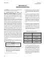
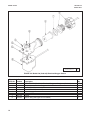
5.1 GENERAL. This section contains the replacement parts lists and illustrations for the Model 430 Sensor Assembly.
Parts are keyed with an item number. Use the illustration to locate the item number for the part in question. Then refer
to the accompanying parts list for the part number, description and quantity needed. The Usage Code column, where
used, identifies parts used on more than one assembly. If there is no code letter, the item is used on all assemblies
in that parts list.
DWG. NO.
REV.
40045052
A
FIGURE 5-1. Model 430 (Codes 01 and 02) Dissolved Oxygen Sensor
Figure &
Item No.
5-1 A
B
3
4
5
7
8
9
Part
Number
2002566
2002567
9550090
1001021
3001197
Description
SENSOR ASSY, Model 430 Dissolved Oxygen, angle flow (Code 01 )
SENSOR ASSY, Model 430 Dissolved Oxygen, straight flow (Code 02)
Tee Assy, angle flow
Tee Assy, straight flow
Union, 1” NPT
O-ring (Buna-N, 2-029)
Sensor Assy (see Figure 5-2 for details)
Gasket
Usage
Code Qty.
A
RF
B
RF
A
B
11
MODEL 430 DO
SECTION 5.0
PARTS LISTS
DWG. NO.
40043016
REV.
A
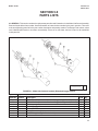
FIGURE 5-2. Model 430 Sensor Assembly
Part Number
3002384
9550116
2002572
3002385
9550133
3002382
2002473
12
Description
Base
O-ring (2-018)*
Reservoir housing assembly with membrane*
Retainer ,reservoir
O-ring (2-004)
Screw, vent
Recharge Kit
Qty.
1
1
1
1
1
1
1
MODEL 430 DO
SECTION 5.0
PARTS LISTS
DWG. NO.
40043015
REV.
A
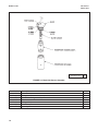
FIGURE 5-3. Model 430 (Code 03) Dissolved Oxygen Sensor
Figure &
Part
Item No. Number
5-3
2
9330020
3
3001617
4
1001021
Description
SENSOR ASSY, Model 430 Dissolved Oxygen, submersion (Code 13)
Union, 3/4” NPT
Gasket
Sensor Assy (see Figure 5-2 for details)
Qty.
RF
RF
1
1
13
MODEL 430 DO
SECTION 5.0
PARTS LISTS
DWG. NO.
40043017
REV.
A
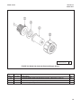
FIGURE 5-4. Model 430 (Code 04) Dissolved Oxygen Sensor
Figure &
Item No.
5-4
2
3
4
5
6
7
8
14
Part
Number
9380053
3001150
9320057
3001197
1001021
Description
SENSOR ASSY, Model 430 Dissolved Oxygen, with agitator (Code 04)
Pump, submersible Attaching parts for item 2:
Screw, SPH SS (#8-32x3/8)
Screw, SPH SS (#8-32x3/8)
Holder Assy
Union, 1” NPT
Gasket
Sensor assy (see Figure 5-2 for details)
Qty.
1
1
4
2
1
1
1
1
Model 430 DO
SECTION 6.0
RETURN OF MATERIAL
SECTION 6.0
RETURN OF MATERIAL
6.1 GENERAL. To expedite the repair and return of
instruments, proper communication between the customer and the factory is important. A return material
authorization (RMA) number is required. Call (949)
757-8500. The "Return of Materials Request" form is
provided for you to copy and use in case the situation
arises. The accuracy and completeness of this form
will affect the processing time of your materials.
6.2 WARRANTY REPAIR. The following is the procedure for returning instruments still under warranty.
1.
Contact the factory for authorization.
2.
Complete a copy of the “Return of Materials
Request” form as completely and accurately as
possible.
3.
To verify warranty, supply the factory sales order
number or the original purchase order number. In
the case of individual parts or sub-assemblies, the
serial number on the mother unit must be supplied.
4.
Carefully package the materials and enclose your
“Letter of Transmittal” and the completed copy of
the “Return of Materials Request” form. If possible, pack the materials in the same manner as it
was received.
5.
Send the package prepaid to:
Rosemount Analytical Inc.
2400 Barranca Parkway
Irvine, CA 92606
Attn: Factory Repair
Mark the package: Returned for Repair RMA#
Model No. ____
6.3 NON WARRANTY REPAIR. Contact Factory For
Authorization
1.
Contact the factory for authorization.
2.
Fill out a copy of the “Return of Materials Request”
form as completely and accurately as possible.
3.
Include a purchase order number and make sure
to include the name and telephone number of the
right individual to be contacted should additional
information be needed.
4.
Do Steps 4 and 5 of Section 6.2.
NOTE
Consult the factory for additional information regarding service or repair.
IMPORTANT
Please see second section of “Return of
Materials Request Form”. Compliance to
the OSHA requirements is mandatory for
the safety of all personnel. MSDS forms
and a certification that the instruments
have been disinfected or detoxified are
required.
15
MODEL CFA 3000
RETURN OF MATERIAL
RETURN OF MATERIAL
GENERAL.
To expedite the repair and return of instruments, proper communication between the customer and the factory is
important. Before returning a product for repair, call 1-949-757-8500 for a Return Materials Authorization (RMA)
number.
WARRANTY REPAIR.
The following is the procedure for returning instruments still under warranty:
1.
Call Emerson Process Management for authorization.
2.
To verify warranty, supply the factory sales order number or the original purchase order number. In the case
of individual parts or sub-assemblies, the serial number on the unit must be supplied.
3.
Carefully package the materials and enclose your “Letter of Transmittal” (see Warranty). If possible, pack the
materials in the same manner as they were received.
4.
Send the package prepaid to:
Emerson Process Management
Liquid Division
2400 Barranca Parkway
Irvine, CA 92606
Attn: Factory Repair
RMA No. ____________
Mark the package: Returned for Repair
Model No. ____
NON-WARRANTY REPAIR.
The following is the procedure for returning for repair instruments that are no longer under warranty:
1.
Call Emerson Process Management for authorization.
2.
Supply the purchase order number, and make sure to provide the name and telephone number of the individual to be contacted should additional information be needed.
3.
Do Steps 3 and 4 of the Warranty Repair section above.
NOTE
Consult the factory for additional information regarding service or repair.
The right people, the right answers, right now.
Immediate, Reliable Analytical Support
Now there’s a way to quickly get the right answers for your liquid analytical instrumentation questions: the Analytical Customer Support Center.
Our staff of trained professionals is ready to provide the information you need. If you are placing an
order, verifying delivery, requesting application information, or just want to contact a Rosemount
Analytical representative, a call to the Customer Support Center will provide you with the right people, the right answers, right now.
A Worldwide Network of Sales and Service
Emerson Process Management’s field sales offices are your source for more information on the fill line of Rosemount Analytical
products. Field sales personnel will work closely with you to supply technical data and application information.
For more information, please contact your nearest Emerson Process Management sales office.
THE AMERICAS HEADQUARTERS
Emerson Process Management
Rosemount Analytical Inc.
Liquid Center of Excellence
2400 Barranca Parkway
Irvine, CA 92606
Phone: +1.949.757.8500
Toll Free: +1.800.854.8257
Fax: +1.949.474.7250
ASIA-PACIFIC
Emerson Process Management
Asia Pacific Private Ltd.
1 Pandan Crescent
Singapore 0512
Republic of Singapore
Phone: 65.777.8211
Fax: 65.777.0947
GERMANY
Emerson Process Management Process
Gas Analyzer Center of Excellence
GmbH & Co. OHG
Industriestrasse 1
63594 Hasselroth
Germany
T 49.6055.884.0
F 49.6055.884.20
LATIN AMERICA
Emerson Process Management
Rosemount Analytical
10241 West Little York, Suite #200
Houston, TX 77040 USA
T 713.467.6000
F 713.827.3328
MIDDLE EAST AND AFRICA
EUROPE
Emerson Process Management AG
Blegistrasse 21
CH-6341 Baar-Walterswil
Switzerland
T 41.41.768.6111
T 41.41.761.8740
VISIT OUR WEBSITE AT
www.rosemountanalytical.com
Emerson Process Management
EPM Building
P. O. Box 17033
Jebe Ali Free Zone
Dubai, United Arab Emirates
T 971.4.8835235
F 971.4.8835312
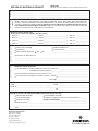
RETURN OF MATERIALS REQUEST
C
U
S
T
O
M
E
R
N
O
T
I
C
E
T
O
FROM:
•IMPORTANT!
This form must be completed to ensure expedient factory service.
RETURN
BILL TO:
_____________________________
_____________________________
_____________________________
_____________________________
_____________________________
_____________________________
_____________________________
_____________________________
_____________________________
S
E
N
D
E
R
CUSTOMER/USER MUST SUBMIT MATERIAL SAFETY SHEET (MSDS) OR COMPLETE STREAM COMPOSITION, AND/OR
LETTER CERTIFYING THE MATERIALS HAVE BEEN DISINFECTED AND/OR DETOXIFIED WHEN RETURNING ANY
PRODUCT, SAMPLE OR MATERIAL THAT HAVE BEEN EXPOSED TO OR USED IN AN ENVIRONMENT OR PROCESS THAT
CONTAINS A HAZARDOUS MATERIAL ANY OF THE ABOVE THAT IS SUBMITTED TO ROSEMOUNT ANALYTICAL WITHOUT THE MSDS WILL BE RETURNED TO SENDER C.O.D. FOR THE SAFETY AND HEALTH OF OUR EMPLOYEES. WE
THANK YOU IN ADVANCE FOR COMPLIANCE TO THIS SUBJECT.
SENSOR OR CIRCUIT BOARD ONLY:
(Please reference where from in MODEL / SER. NO. Column)
1. PART NO.__________________________1. MODEL_________________________________1.
SER. NO. ________________
2. PART NO.__________________________2. MODEL_________________________________2.
SER. NO. ________________
3. PART NO.__________________________3. MODEL_________________________________3.
SER. NO. ________________
4. PART NO.__________________________4. MODEL_________________________________4.
SER. NO. ________________
R
E
A
S
O
N
PLEASE CHECK ONE:
F
O
R
n REPLACEMENT REQUIRED? n YES n NO
R
E
T
U
R
N
R
E
P
A
I
R
S
T
A
T
U
S
n REPAIR AND CALIBRATE
n DEMO EQUIPMENT NO. __________________________
n EVALUATION
n OTHER (EXPLAIN) _______________________________
_________________________________________________
DESCRIPTION OF MALFUNCTION:
______________________________________________________________________________________________________
______________________________________________________________________________________________________
______________________________________________________________________________________________________
WARRANTY REPAIR REQUESTED:
n YES-REFERENCE ORIGINAL ROSEMOUNT ANALYTICAL ORDER NO. ________________________________________
CUSTOMER PURCHASE ORDER NO. _________________________________________________
n NO-PROCEED WITH REPAIRS-INVOICE AGAINST P.O. NO. _________________________________________________
n NO-CONTACT WITH ESTIMATE OF REPAIR CHARGES: LETTER n __________________________________________
PHONE n ___________________________________________
NAME ____________________________________________________
PHONE _________________________________________
ADDRESS ___________________________________________________________________________________________________
______________________________________________________________
ZIP _________________________________________
RETURN AUTHORITY FOR CREDIT ADJUSTMENT [Please check appropriate box(s)]
n WRONG PART RECEIVED
n REPLACEMENT RECEIVED
n DUPLICATE SHIPMENT
REFERENCE ROSEMOUNT ANALYTICAL SALES ORDER NO. _________
n RETURN FOR CREDIT
RETURN AUTHORIZED BY: ______________________________________
WARRANTY DEFECT____________________________________________________________________________________
_____________________________________________________________________________________________________
24-6047
Emerson Process Management
Rosemount Analytical Inc.
2400 Barranca Parkway
Irvine, CA 92606 USA
Tel: (949) 757-8500
Fax: (949) 474-7250
http://www.RAuniloc.com
© Rosemount Analytical Inc. 2001
WARRANTY
Seller warrants that the firmware will execute the programming instructions provided by Seller, and that the Goods manufactured
or Services provided by Seller will be free from defects in materials or workmanship under normal use and care until the expiration of the applicable warranty period. Goods are warranted for twelve (12) months from the date of initial installation or eighteen
(18) months from the date of shipment by Seller, whichever period expires first. Consumables, such as glass electrodes,
membranes, liquid junctions, electrolyte, o-rings, catalytic beads, etc., and Services are warranted for a period of 90
days from the date of shipment or provision.
Products purchased by Seller from a third party for resale to Buyer ("Resale Products") shall carry only the warranty extended by
the original manufacturer. Buyer agrees that Seller has no liability for Resale Products beyond making a reasonable commercial
effort to arrange for procurement and shipping of the Resale Products.
If Buyer discovers any warranty defects and notifies Seller thereof in writing during the applicable warranty period, Seller shall, at
its option, promptly correct any errors that are found by Seller in the firmware or Services, or repair or replace F.O.B. point of manufacture that portion of the Goods or firmware found by Seller to be defective, or refund the purchase price of the defective portion of the Goods/Services.
All replacements or repairs necessitated by inadequate maintenance, normal wear and usage, unsuitable power sources, unsuitable environmental conditions, accident, misuse, improper installation, modification, repair, storage or handling, or any other
cause not the fault of Seller are not covered by this limited warranty, and shall be at Buyer's expense. Seller shall not be obligated to pay any costs or charges incurred by Buyer or any other party except as may be agreed upon in writing in advance by an
authorized Seller representative. All costs of dismantling, reinstallation and freight and the time and expenses of Seller's personnel for site travel and diagnosis under this warranty clause shall be borne by Buyer unless accepted in writing by Seller.
Goods repaired and parts replaced during the warranty period shall be in warranty for the remainder of the original warranty period or ninety (90) days, whichever is longer. This limited warranty is the only warranty made by Seller and can be amended only
in a writing signed by an authorized representative of Seller. Except as otherwise expressly provided in the Agreement, THERE
ARE NO REPRESENTATIONS OR WARRANTIES OF ANY KIND, EXPRESS OR IMPLIED, AS TO MERCHANTABILITY, FITNESS FOR PARTICULAR PURPOSE, OR ANY OTHER MATTER WITH RESPECT TO ANY OF THE GOODS OR SERVICES.
RETURN OF MATERIAL
Material returned for repair, whether in or out of warranty, should be shipped prepaid to:
Emerson Process Management
Liquid Division
2400 Barranca Parkway
Irvine, CA 92606
The shipping container should be marked:
Return for Repair
Model _______________________________
The returned material should be accompanied by a letter of transmittal which should include the following information (make a
copy of the "Return of Materials Request" found on the last page of the Manual and provide the following thereon):
1.
2.
3.
4.
5.
Location type of service, and length of time of service of the device.
Description of the faulty operation of the device and the circumstances of the failure.
Name and telephone number of the person to contact if there are questions about the returned material.
Statement as to whether warranty or non-warranty service is requested.
Complete shipping instructions for return of the material.
Adherence to these procedures will expedite handling of the returned material and will prevent unnecessary additional charges
for inspection and testing to determine the problem with the device.
If the material is returned for out-of-warranty repairs, a purchase order for repairs should be enclosed.
The right people,
the right answers,
right now.
ON-LINE ORDERING NOW AVAILABLE ON OUR WEB SITE
http://www.raihome.com
Specifications subject to change without notice.
Credit Cards for U.S. Purchases Only.
Emerson Process Management
Liquid Division
2400 Barranca Parkway
Irvine, CA 92606 USA
Tel: (949) 757-8500
Fax: (949) 474-7250
http://www.raihome.com
© Rosemount Analytical Inc. 2005