1
ENGLISH
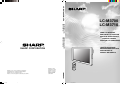
LC-M3700/LC-M3710
OPERATION MANUAL
BEDIENUNGSANLEITUNG
MODE D’EMPLOI
MANUAL DE MANEJO
STANDBY/ON
INPUT
VOL
RETURN
MENU
ENTER
ENLARGE
Printed on 100% post-consumer recycled paper.
Gedruckt auf 100% wiederverwertungs Papier.
Imprimé sur 100% de papier recyclé.
Impreso en 100% de papel reciclado de postconsumo.
Cover.p65
1
Printed in Japan
Gedruckt in Japan
Imprimé au Japon
Impreso en Japón
TINS-A842WJZZ
03P07-JKK
WIDE
LCD MONITOR
03.7.25, 1:24 PM
ESPAÑOL
SHARP CORPORATION
FRANÇAIS
BEDIENUNGSANLEITUNG
MANUAL DE MANEJO
WIDE LCD MONITOR
BREITBILD-LCD-MONITOR
MONITEUR GRAND ÉCRAN À
CRISTAUX LIQUIDES
MONITOR LCD PANORÁMICO
DEUTSCH
OPERATION MANUAL
MODE D’EMPLOI
LC-M3700
LC-M3710
ENGLISH
LC-M3700
LC-M3710
WIDE LCD MONITOR
ENGLISH
OPERATION MANUAL
IMPORTANT:
To aid reporting in case of loss or theft, please
record the product’s model and serial numbers in
the space provided. The numbers are located in
the rear of the product.
Model No.:
Serial No.:
U.S.A. ONLY
IMPORTANT INFORMATION
WARNING: TO REDUCE THE RISK OF FIRE OR ELECTRIC SHOCK, DO NOT EXPOSE
THIS PRODUCT TO RAIN OR MOISTURE.
CAUTION
RISK OF ELECTRIC
SHOCK
DO NOT OPEN
CAUTION: TO REDUCE THE RISK OF
ELECTRIC SHOCK, DO NOT
REMOVE COVER.
NO USER-SERVICEABLE PARTS
INSIDE.
REFER SERVICING TO QUALIFIED
SERVICE PERSONNEL.
The lightning flash with arrowhead symbol,
within an equilateral triangle, is intended to
alert the user to the presence of
uninsulated “dangerous voltage” within the
product’s enclosure that may be of
sufficient magnitude to constitute a risk of
electric shock to persons.
The exclamation point within a triangle is
intended to alert the user to the presence
of important operating and maintenance
(servicing) instructions in the literature
accompanying the product.
1
US
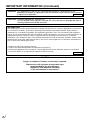
IMPORTANT INFORMATION (Continued)
WARNING: FCC Regulations state that any unauthorized changes or modifications to this
equipment not expressly approved by the manufacturer could void the user’s authority
to operate this equipment.
U.S.A. ONLY
CAUTION: Use the supplied AC cord as it is.
Do not remove the core part from the AC cord, and do not change the way of
winding cables around the core part.
INFORMATION:
This equipment has been tested and found to comply with the limits for a Class A digital device, pursuant to
Part 15 of the FCC Rules. These limits are designed to provide reasonable protection against harmful
interference in a residential installation. This equipment generates, uses, and can radiate radio frequency
energy and, if not installed and used in accordance with the instructions, may cause harmful interference to
radio communications. However, there is no guarantee that interference will not occur in a particular
installation. If this equipment does cause harmful interference to radio or television reception, which can be
determined by turning the equipment off and on, the user is encouraged to try to correct the interference by
one or more of the following measures:
•
•
•
•
Relocate or adjust the receiving antenna.
Increase the separation between the equipment and receiver.
Connect the equipment into an outlet on a circuit different from that to which the receiver is connected.
Consult the dealer or an experienced radio/TV technician for help.
U.S.A. ONLY
CAUTION
Danger of explosion if battery is incorrectly replaced.
Replace only with the same or equivalent type
recommended by the manufacturer.
Dispose of used batteries according
to the manufacturer’s instructions.
US
2
DEAR SHARP CUSTOMER
Introduction
Thank you for your purchase of a SHARP LCD product. To ensure safety and many
years of trouble-free operation of your product, please read the Safety Precautions
carefully before using this product.
SAFETY PRECAUTIONS
Connection
and Installation
Electricity is used to perform many useful functions, but it can also cause personal injuries and property damage
if improperly handled. This product has been engineered and manufactured with the highest priority on safety.
However, improper use can result in electric shock and/or fire. In order to prevent potential danger, please
observe the following instructions when installing, operating and cleaning the product. To ensure your safety
and prolong the service life of your LCD product, please read the following precautions carefully before using
the product.
1. Read instructions—All operating instructions must be read and understood before the product is operated.
2. Keep this manual in a safe place—These safety and operating instructions must be kept in a safe place
for future reference.
3. Observe warnings—All warnings on the product and in the instructions must be observed closely.
4. Follow instructions—All operating instructions must be followed.
5. Cleaning—Unplug the power cord from the AC outlet before cleaning the product. Use a damp cloth to
clean the product. Do not use liquid cleaners or aerosol cleaners.
6. Attachments—Do not use attachments not recommended by the manufacturer. Use of inadequate attachments can result in accidents.
7. Water and moisture—Do not use the product near water, such as bathtub, washbasin, kitchen sink and
laundry tub, swimming pool and in a wet basement.
8. Stand—Do not place the product on an unstable cart, stand, tripod or table. Placing the product on an
unstable base can cause the product to fall, resulting in serious personal injuries as well as damage to
the product. Use only a cart, stand, tripod, bracket or table recommended by the manufacturer or sold
with the product. When mounting the product on a wall, be sure to follow the manufacturer’s instructions.
Use only the mounting hardware recommended by the manufacturer.
9. When relocating the product placed on a cart, it must be moved with utmost care.
Sudden stops, excessive force and uneven floor surface can cause the product to fall
from the cart.
10. Ventilation—The vents and other openings in the cabinet are designed for ventilation.
Do not cover or block these vents and openings since insufficient ventilation can cause
overheating and/or shorten the life of the product. Do not place the product on a bed,
sofa, rug or other similar surface, since they can block ventilation openings. Do not
place the product in an enclosed place such as a bookcase or rack, unless proper
ventilation is provided or the manufacturer’s instructions are followed.
11. Power cord protection—The power cords must be routed properly to prevent people from stepping on
them or objects from resting on them.
12. The LCD panel used in this product is made of glass. Therefore, it can break when the product is
dropped or applied with impact. Be careful not to be injured by broken glass pieces in case the LCD
panel breaks.
13. Overloading—Do not overload AC outlets or extension cords. Overloading can cause fire or electric
shock.
14. Entering of objects and liquids—Never insert an object into the product through vents or openings. High
voltage flows in the product, and inserting an object can cause electric shock and/or short internal parts.
For the same reason, do not spill water or liquid on the product.
15. Servicing—Do not attempt to service the product yourself. Removing covers can expose you to high
voltage and other dangerous conditions. Request a qualified service person to perform servicing.
Basic Operation
PC Operation
Settings and
Adjustments
Troubleshooting and
Specifications
Appendix
3
US
SAFETY PRECAUTIONS (Continued)
16. Repair—If any of the following conditions occurs, unplug the power cord from the AC outlet, and request
a qualified service person to perform repairs.
a. When the power cord or plug is damaged.
b. When a liquid was spilled on the product or when objects have fallen into the product.
c. When the product has been exposed to rain or water.
d. When the product does not operate properly as described in the operating instructions.
Do not touch the controls other than those described in the operating instructions. Improper adjustment of controls not described in the instructions can cause damage, which often requires extensive
adjustment work by a qualified technician.
e. When the product has been dropped or damaged.
f. When the product displays an abnormal condition. Any noticeable abnormality in the product indicates
that the product needs servicing.
17. Replacement parts—In case the product needs replacement parts, make sure that the service person
uses replacement parts specified by the manufacturer, or those with the same characteristics and performance as the original parts. Use of unauthorized parts can result in fire, electric shock and/or other
danger.
18. Safety checks—Upon completion of service or repair work, request the service technician to perform
safety checks to ensure that the product is in proper operating condition.
19. Wall or ceiling mounting—When mounting the product on a wall or ceiling, be sure to install the product
according to the method recommended by the manufacturer.
20. Heat sources—Keep the product away from heat sources such as radiators, heaters, stoves and other
heat-generating products (including amplifiers).
21. Power source—This product must operate on a power source specified on the specification label. If you
are not sure of the type of power supply used in your home, consult your dealer or local power company.
For units designed to operate on batteries or another power source, refer to the operating instructions.
The LCD panel is a very high technology product with 3,147,264 thin film transistors, giving you fine picture
details.
Occasionally, a few non-active pixels may appear on the screen as a fixed point of blue, green or red.
Please note that this does not affect the performance of your product.
WARNING:
To reduce the risk of fire or electric shock, do not expose this product to rain or
moisture.
WARNING:
This is a class A product. In a domestic environment this product may cause radio
interference in which case the user may be required to take adequate measures.
US
4
CONTENTS
Introduction
Page
Dear SHARP Customer ........................................................................... 3
Safety Precautions .................................................................................. 3
Introduction ............................................................................................. 5
Features ................................................................................................. 6
Part Names – Display ............................................................................ 8
Removing the terminal cover ................................................................. 9
Part Names – Remote Control Unit ..................................................... 10
Removing the battery cover ................................................................. 11
Supplied Accessories ........................................................................... 12
Connection and Installation ................................................................. 13
Connecting Peripheral Equipment ....................................................... 13
Connecting external speakers ............................................................. 18
Connecting the AC cord ....................................................................... 19
Connecting multiple monitors ............................................................... 20
Mounting options .................................................................................. 23
Bundling cables .................................................................................... 29
Basic Operation .................................................................................... 30
Turning on Power ................................................................................. 30
Main POWER switch ............................................................................ 30
STANDBY/ON ...................................................................................... 30
Remote Control Unit ............................................................................. 31
Menu Items .......................................................................................... 32
Menu option selection .......................................................................... 32
Menu screen explanation ..................................................................... 33
PC (analog) input mode menu items ................................................... 34
AV input mode menu items .................................................................. 35
Language setting .................................................................................. 36
PC Operation ......................................................................................... 37
PC connection ...................................................................................... 37
Communication conditions ................................................................... 37
Communication procedure ................................................................... 38
RS-232C command table ..................................................................... 46
Settings and Adjustments .................................................................... 51
Picture .................................................................................................. 51
Audio .................................................................................................... 53
Power control ....................................................................................... 53
Setup .................................................................................................... 54
Option ................................................................................................... 57
Detailed explanation ............................................................................. 58
Troubleshooting and Specifications ................................................... 65
Troubleshooting ................................................................................... 65
Specifications ....................................................................................... 67
Optional Accessories ........................................................................... 67
Appendix ................................................................................................ 68
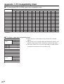
Appendix 1: PC Compatibility Chart .......................................................... 68
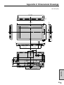
Appendix 2: Dimensional Drawings ........................................................... 69
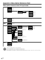
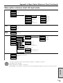
Appendix 3: Menu Option Reference Chart ............................................... 70
5
US
Features
Numbers within
refer to the main page(s) where the topic is explained.
HIGH-DEFINITION (HD) PANEL
A large, flat LCD display panel with 3.15 million pixels lets you enjoy a detailed, high• definition
picture from a digital TV or a PC.
ASV* LOW-REFLECTION BLACK TFT LCD PANEL
unique ASV* low-reflection BLACK TFT LCD panel provides higher luminance,
• SHARP’s
higher contrast, and a wider viewing angle. This reduces reflection in the monitor when it
is placed near a window, and ensures brighter, more vivid image reproduction. With a
wide viewing angle of 170 degrees, both horizontally and vertically, the image is
beautiful, even when viewed off axis.
* ASV … Advanced Super View
CABINET DESIGN ENABLES VERTICAL AND HORIZONTAL
INSTALLATION
mounted vertically, this monitor requires images coded for a vertical screen. It
• When
does not have image rotation capability.
EQUIPPED WITH A VARIETY OF TERMINALS
• INPUT1 Terminals are provided for two types of video input signal.
•
•
•
13
9
54
Input Select
Video Input (BNC-terminal) NTSC (3.58/4.43)/PAL/SECAM (*1)
S-video Input (S-terminal)
NTSC (3.58/4.43)/PAL/SECAM (*1)
INPUT2 This terminal can be set for input or output. 56 INPUT2 Select
Video Input (RCA-terminal) NTSC (3.58/4.43)/PAL/SECAM (*1)
INPUT3 This terminal enables selection of the video signal type. 54 Input Select
COMPONENT/RGB Input (BNC-terminal)
COMPONENT
480i/480p/576i/576p/1080i/720p (*2)
RGB
Conforms to PC analog input. 68 Appendix 1 (*2, *3)
PC
Analog Input (D-Sub terminal) VGA/SVGA/XGA/SXGA and others 68 Appendix 1 (*2, *3)
Digital Input (DVI terminal)
VGA/SVGA/XGA/SXGA and others 68 Appendix 1
*1: There is a setting for auto-detection of the color system. (This is set to “Auto” at factory shipment.)
*2: Frequency is auto-detected.
*3: The INPUT3 (RGB) and PC (analog) inputs are compatible with Sync On Green input. PC (analog) input is
compatible with Csync input.
COMPATIBLE WITH VARIOUS COLOR SYSTEMS
• Compatible with NTSC (3.58/4.43), PAL (50/60) and SECAM.
US
6
57
Features (Continued)
refer to the main page(s) where the topic is explained.
ENLARGEMENT FUNCTION
Introduction
Numbers within
61
56
output of enlarged images for 4- or 9-screen (“2×2” or “3×3”) setups, without using
• aAllows
special-purpose external device.
CHAIN CONNECTION OF MULTIPLE MONITORS
chain connection of monitors using video signal output (composite-video/D-Sub)
• Enables
terminals.
individual control via PC of multiple sets connected in a daisy chain using RS• Enables
232C cables.
20
22
37
EXTERNAL CONTROL AND STATUS MONITORING FROM
A PC
monitor can be controlled in various ways from a PC.
• The
Multiple
monitors can be individually controlled by connecting them in a daisy chain.
•
37
EXTERNAL SPEAKERS CAN BE CONNECTED
37
18
• Compatible speakers: L/R, 8 ohm, 10W or larger
EQUIPPED WITH BUILT-IN MONITOR SPEAKER (MONO)
57
activated from the menu screen, you can check the audio input status using the
• When
built-in monitor speaker (mono).
CONTROL LOCK FUNCTIONS
54
58
monitor is equipped with various operation lock functions to prevent unintended
• The
operation or mischief. (The PIN can be set by the user.)
Fluorescent Tubes
■ The fluorescent tubes in this product have a limited lifetime.
» If the screen gets dark, flashes, or does not turn on, change the fluorescent tubes with new
exclusive ones.
Expected lifetime: ............... 60,000 hours for LC-M3700 (horizontal mount)*
40,000 hours for LC-M3710 (vertical mount)*
*When “Brightness” is set to a center value.
» For more information, please contact your product dealer.
■ Because of the property of fluorescent tubes, the screen may flash during the initial period of use. If
this happens, please turn off the main power switch on the back of the monitor and turn on again to
confirm operation.
7
US
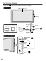
Part Names – Display
Numbers within
refer to the main page(s) where the topic is explained.
Front view
Liquid Crystal Display panel
Side control panel
(See below.)
About LC-M3710:
» The SHARP logo for the LC-M3710 model is
Panel side
on the vertical base.
Remote
control sensor
*
LC-3700
LC-3710
STANDBY/ON
button
11
When using the
remote control, point
it towards here.
STANDBY/ON
indicator
30
Side control panel
MENU
Menu operation
buttons
32
MENU
UP
UP
LEFT RIGHT
DOWN
RIGHT
Cursor
control
LEFT
DOWN
ENTER
ENTER
VOL
INPUT
US
8
VOL +/–
31
INPUT
31
30
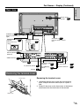
Part Names – Display (Continued)
Introduction
Rear view
Built-in monitor
57
speaker
SPEAKER (R) 18
External speaker terminal
(right)
POWER···················· 30
Main power on/off
switch
AC Input
terminal···············19
INPUT2 (INPUT/ 14
OUTPUT)
VIDEO OUTPUT
SPEAKER (L) 18
External speaker terminal
(left)
2
1
3
17
INPUT1 13
INPUT3/PC (ANALOG)
OUTPUT············ 17
PC (DIGITAL) INPUT
INPUT3
16
PC (ANALOG)
INPUT··················16
RS-232C INPUT··············17
RS-232C OUTPUT········ 17
15
Removing the terminal cover
Lower claw
Removing the terminal cover
1. Hold down the two claws at the top of the terminal
cover, and pull the cover toward you so it opens a
little.
2. Slowly lift the cover so the three claws at the bottom
come loose from the claw holes in the console.
Upper claw
9
US
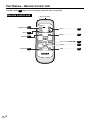
Part Names – Remote Control Unit
Numbers within
refer to the main page(s) where the topic is explained.
Remote control unit
Signal transmitter
STANDBY/ON
STANDBY/ON 30
INPUT 31
INPUT
VOL
RETURN
MENU
VOL +/– ··································31
MENU···································· 32
RETURN 32
ENTER
32
Cursor control ('/"/\/|)············
ENTER·································· 32
ENLARGE
WIDE
ENLARGE 31
WIDE····································· 31
LCD MONITOR
US
10
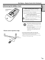
Part Names – Remote Control Unit (Continued)
Introduction
Removing the battery cover
Cautions regarding remote control unit
Gently hold down and
press in the arrow
direction.
» Do not expose the remote control unit to shock. In addition, do not
expose the remote control unit to liquids, and do not place it in an
area with high humidity.
» The remote control unit may not work properly if the remote control
sensor is under direct sunlight or strong lighting.
In such cases, change the angle of the lighting or the monitor, or
operate the remote control unit closer to the remote control sensor.
Cautions regarding batteries
Improper use of batteries can result in chemical leakage
or explosion. Be sure to follow the instructions below.
» Do not mix old and new batteries, or batteries of different
types.
» Do not charge or disassemble batteries.
Caution » Place batteries with their terminals corresponding to the
± and — as indicated in the compartment.
» Do not short-circuit the batteries.
NOTE:
Remote control operation range
» The batteries supplied with this product may
have a shorter life expectancy due to storage
conditions. Replace with new batteries at the
earliest opportunity.
» If you will not use the remote control for a long
time, remove its batteries.
» If the remote control does not work, even with
new batteries, take the batteries out, check
whether they are facing the right way, then
replace them.
If the remote control unit does not work well:
» Objects between the remote control unit and the remote
control sensor may prevent proper operation.
» Replace the batteries when they run low as this may shorten
the remote control operation range.
Remote
control sensor
6m
7m
10°
6m
10°
11
US
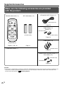
Supplied Accessories
Make sure the following accessories are provided
with the product.
Remote control unit (× 1)
“AA” size battery (× 2)
AC cord, 9 ft.10-1/8″(3 m) (× 1)
STANDBY/ON
(QACCDA024WJPZ)
INPUT
VOL
RETURN
MENU
Page 19
Cable clamp (× 1)
Screw (× 1)
ENTER
(XTBS940P-16000)
ENLARGE
WIDE
(LHLDW1118CEZZ)
(UBATU0013TAZZ)
Page 19
LCD MONITOR
Cable binder (× 3)
(RRMCGA186WJSA)
Pages 11, 30 - 32
Page 11
» Operation manual × 1
(LHLDWA017WJKA)
Page 29
Terminal cover mounting screw (× 2)
Flat washer (× 2)
(XWHS960-16180)
(XBBS960P20000)
Page 29
Caution:
» This monitor is equipped with a temporary stand when shipped from the factory. Please note this stand is for temporary use
only until the monitor is properly mounted. Be sure to use a special-purpose AN-37ST1 table stand or AN-37AG1 wallmount bracket (both optional). 23 Mounting Options.
US
12
Connecting Peripheral Equipment
Introduction
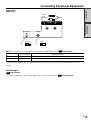
INPUT1
INPUT1
audio
INPUT 1
1
S-VIDEO
S-video
VIDEO
Video
■ INPUT1: Terminals are provided for two types of video input signal. 54
Terminal type
Connection
and Installation
R - AUDIO - L
Input Select
Compatible signals
Video
BNC
NTSC (3.58/4.43), PAL, SECAM (*1)
S-video
S terminal
NTSC (3.58/4.43), PAL, SECAM (*1)
No matter which video signal is selected, the system uses the signal input to the audio terminals for
audio.
Related topic:
54
Input Select
*1 “Auto” (automatic color system detection) is factory preset value. 57
Color System
13
US
Connecting Peripheral Equipment (Continued)
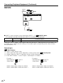
INPUT2
INPUT2
audio
INPUT 2 (INPUT/OUTPUT)
2
R - AUDIO - L
VIDEO
Video
■ INPUT2: Input or output can be selected for INPUT2. (*1) 56 INPUT2 Select
This setting cannot be switched when INPUT2 is currently being displayed.
Terminal type
Video
RCA
Compatible signals
NTSC (3.58/4.43), PAL, SECAM (*2)
When this is set to “Output”, video signals input from the INPUT1 video input terminal are output. (*3)
An audio signal is output with this setting (i.e. the audio signal corresponding to the video currently
being displayed). (*4)
Related topic:
56
*1
*2
*3
*4
INPUT2 Select
“Input” is factory preset value.
“Auto” (automatic color system detection) is factory preset value. 57 Color System
Outputs video from INPUT1, regardless of the currently displayed signal.
If the “INPUT2 Select” is set to “Output”, audio output is as follows.
Example 1
Input Selection 31
“Input Select”
54
: INPUT1
: AV
INPUT2 video output: Video from INPUT1
INPUT2 audio output: Audio from INPUT1
US
14
Example 2
Input Selection
“Input Select”
31
54
: INPUT3
: RGB
INPUT2 video output: Video from INPUT1
INPUT2 audio output: Audio from INPUT3
Connecting Peripheral Equipment (Continued)
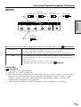
INPUT3
Input Select: RGB
Horizontal
sync signal (H sync)
Y/G
Pb/Cb/B
Pr/Cr/R
INPUT3 audio
Connection
and Installation
INPUT 3
Vertical
sync signal (V sync)
3
HD
VD
AUDIO
Input Select:
COMPONENT
■ INPUT3:
Either COMPONENT or RGB can be selected for the input video signal. 54
56
COMPONENT
RGB
Input Select
The signal is input with the Y/Pb/Pr (Y/Cb/Cr) terminals. The HD and VD terminals are
not used. Video adjustment options on the menu are the AV type.
Compatible input range: 480i/576i, 480p/576p, 1080i (50Hz (*4) /60Hz), 720p (60Hz). (*1)
The monitor operates using Video (RGB) and Sync (HD/VD) signals, just like a PC
(analog). Supported sync signals are ordinary separate sync (HD/VD) and Sync On
Green. (*2) (*3)
Video adjustment options on the menu are the PC type.
Compatible input range: Conforms to PC (analog). 68 Appendix 1
Related topic:
56
54
Input Select
*1 Auto-detects video signal frequency.
*2 Automatic sync signal type detection
*3 Sync signal presence is detected in the order: Separate Sync → Sync On Green. If for some reason
Separate Sync is not input, the system will operate assuming that the signal is a Sync On Green
signal (i.e. that the sync signal is contained in the G signal of RGB), and this may result in an
unstable image, depending on the video signal.
*4 1080i (50Hz) corresponds to a SMPTE274M signal. (Horizontal frequency is 28.125kHz)
15
US
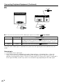
Connecting Peripheral Equipment (Continued)
PC
PC audio
PC(DIGITAL)INPUT
PC(ANALOG)INPUT
AUDIO
PC (digital) video
PC (analog) video
■ PC: Terminals for two kinds of PC video input signal are available. 54 56
Input Select
Terminal type
Analog
D-Sub15-pin
Digital
DVI-D
Compatible signals
VGA, SVGA, XGA, SXGA and others 68 Appendix 1
In addition to ordinary Separate Sync (HD/VD) signals, the system is also
compatible with Composite Sync (Csync) and Sync On Green. (*1) (*2)
VGA, SVGA, XGA, SXGA and others 68
Appendix 1
No matter which video signal is selected, the system uses the signal input to the audio terminals for
audio.
Related topic:
*1 Auto-detects Sync signal type.
*2 Sync signal presence is detected in the order: Separate Sync → Composite Sync → Sync On
Green. If for some reason neither Separate Sync nor Composite Sync is input, the system will
operate assuming that the signal is a Sync On Green signal (i.e. that the sync signal is contained in
the G signal of RGB), and this may result in an unstable image, depending on the video signal.
US
16
Connecting Peripheral Equipment (Continued)
VIDEO OUTPUT
VIDEO
OUTPUT
Connection
and Installation
Video
■ When INPUT2 is displayed, video from INPUT2 is output. Otherwise video from INPUT1 is output.
INPUT3/PC (ANALOG) OUTPUT
INPUT 3 / PC (ANALOG) OUTPUT
■ When INPUT3 is displayed, video from INPUT3 is output. Otherwise PC (analog) video is output.
RS-232C INPUT/RS-232C OUTPUT
RS-232C INPUT
RS-232C OUTPUT
■ The RS-232C INPUT and RS-232C OUTPUT are used to control this monitor with a PC.
To connect a single monitor to a PC, connect to the RS-232C INPUT terminal.
To connect multiple monitors in a daisy chain for control by PC, use the RS-232C OUTPUT terminal.
37
17
US
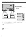
Connecting External Speakers
"Rear view
Speaker compatibility:
» Be sure to use external speakers with an
impedance of 8 ohm and a rated input of
at least 10W.
To external
speaker (right)
"SPEAKER R
terminal
To external speaker
(left)
"SPEAKER L
terminal
How to connect the speaker
cables
1 Pull up the lid.
2 Insert the edge
of the cable.
3 Put the lid back
down.
Make sure to connect the speaker jack and cable polarity (±, —) properly.
■ The speaker jacks have plus ± and minus — polarity. Plus is red and minus is black.
The cables are also divided into plus and minus.
When connecting the left/right speakers, be sure to connect the plus/minus jacks with the correct
cables.
NOTE:
US
18
» You can output audio from the built-in monitor speaker on the back of the monitor. See “Monitor Speaker Output”
on page 57 for details.
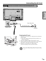
Connecting the AC Cord
Caution
Be sure to turn the main POWER off when connecting the cord.
"Rear view
Connection
and Installation
Plug (to the AC
input terminal)
Plug (to power outlet)
'AC input terminal
(plug in here)
AC cord 9 ft. 10-1/8″ (3 m)
Power outlet
Fastening the AC cord
Attaching portion
Screw
1. Plug the AC cord into the AC input terminal on the back
of the monitor.
» Align the shape of the plug and the connector, and
insert all the way in.
2. Attach the supplied cable clamp to the AC cord.
3. Align the hole of the cable clamp with the screw hole on
the monitor, and fasten the cable clamp screw.
4. Plug the AC cord into the AC power outlet.
» Be sure to plug all the way into the socket.
Cable clamp
NOTE:
» When connecting the power cord to the main unit, always
use the cable clamp to keep the power cord from coming
loose.
19
US
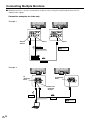
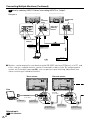
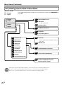
Connecting Multiple Monitors
■ Multiple monitors can be connected in a daisy chain using the input/output terminals for
video/audio signals.
Connection examples for video only
Example: 1
2
1
VIDEO
OUTPUT
2
1
INPUT 1
INPUT 1
Video cable
shows the
signal flow.
To video output terminal
External device
Video cable
Example: 2
PC
(ANALOG)
INPUT
PC(ANALOG)
INPUT
00
00
INPUT 3/PC
(ANALOG)
OUTPUT
RGB cable
To video output terminal
RGB cable
shows the
signal flow.
US
20
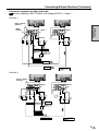
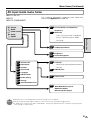
Connecting Multiple Monitors (Continued)
Connection examples for video and audio
Use by selecting “INPUT2 Select” and setting INPUT2 to “Output”.
56
Example: 1
INPUT 2 (INPUT/
OUTPUT)
2
INPUT 1
1
2
1
INPUT 1
(Red:
audio
right)
(White:
audio
left)
(Red:
audio
right)
(White:
audio
left)
Connection
and Installation
VIDEO
OUTPUT
(Red:
audio
right)
(White:
audio
left)
Audio cable
Video cable
To video output
terminal
To audio output
terminal
External device
Video cable
Audio cable
shows the
signal flow.
Example: 2
INPUT 2 (INPUT/
OUTPUT)
2
(Red:
audio
right)
(White:
audio
left)
(Yellow:
video)
1
INPUT 1
(Red:
audio
right)
(White:
audio
left)
2
RCA-BNC
conversion
adapter
(Yellow:
video)
Video cable
To video output
terminal
1
INPUT 1
(Red:
audio
right)
(White:
audio
left)
Audio cable
To audio output
terminal
External device
Video/audio cable
shows the
signal flow.
21
US
Connecting Multiple Monitors (Continued)
56
Use by selecting “INPUT2 Select” and setting INPUT2 to “Output”.
Example: 3
PC(ANALOG)
INPUT
PC
(ANALOG)
INPUT
2
1
INPUT 3/PC
(ANALOG)
OUTPUT
(Red:
audio
right)
(White:
audio
left)
INPUT 2 (INPUT/
OUTPUT)
RGB cable
To video output
terminal
RGB cable
PC audio cable
To PC audio output
terminal
shows the
signal flow.
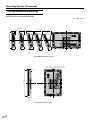
■ Monitors can be externally controlled using the RS-232C interface (COM port) of a PC, and,
in this case too, multiple monitors can be connected in a daisy chain. By assigning each
monitor an ID number (see page 56), you can perform input switching, adjustment and
status monitoring of individual monitors.
"First monitor
"Second monitor
"PC
RS-232C
cross cable
RS-232C
cross cable
To COM port
To RS-232C
INPUT terminal
To RS-232C
OUTPUT terminal
Related topic:
37
US
22
PC Operation
To RS-232C
INPUT terminal
To RS-232C
OUTPUT terminal
Mounting Options
■ Please use an optional table stand or wall-mount bracket designed specifically for this
product.
This monitor is equipped with a temporary stand when shipped from the factory. Please
note this stand is for temporary use only until the monitor is properly mounted. Be sure to
use a special-purpose AN-37ST1 table stand or AN-37AG1 wall-mount bracket (both
optional).
Mounting
precautions
Connection
and Installation
Mounting the table stand (AN-37ST1) (LC-M3700)
See the table stand instructions for details.
1. Assemble the table stand.
M5 screws 25 mm length
(5 screws)
● Align the 5 screw holes of the stand base with
the corresponding screw holes of the stand
hinge. Then attach the stand base to the stand
hinge using the supplied 5 screws (M5 25 mm
length).
Stand base
Stand hinge
2. Detach the temporary stand.
Terminal cover
Wide LCD Monitor
●Place the monitor (face down) on a table, etc.
covered by a thick, soft cloth for LCD panel
protection.
●Position the monitor near the edge of the table so
that the temporary stand does not hit the table,
then remove the terminal cover.
●Unfasten the 4 screws used to secure the
temporary stand in place, then remove the stand.
Temporary stand
Table
Soft cloth, etc.
M5 screws 12 mm length
(4 screws)
3. Attach the table stand assembled in
step 1 to the back of the monitor using
the supplied 4 screws (M5 12 mm
length).
●After installation, close the terminal cover, and
adjust the monitor to a suitable angle. (Tilting
range: up to 4˚ forward and 6˚ backward.
Rotating range: up to 10˚ clockwise and
anticlockwise.)
Table stand
23
US
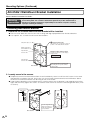
Mounting Options (Continued)
AN-37AG1 Wall-Mount Bracket Installation
See the bracket instructions for details.
Mounting
precautions
Special techniques are required to mount this monitor, so be sure to rely on a specialist
for mounting work. The customer should never perform any of this work himself or
herself. Our company will bear no responsibility for accidents or injuries caused by
improper mounting or handling.
Installing wall-mount bracket
1. Determine the location where the base bracket will be installed.
● Take a washer about the size of a coin with a string and align it perpendicular to the base bracket.
● Use a pencil, etc., to mark the two screw hole locations.
Cellophane tape, etc.
shaped screw holes
Use a pencil, etc., to mark the screw hole
position on the wall behind the bracket.
Wall-mount bracket
unit installation hooks
Perpendicular
reference line
Display screen center position
Use this as a reference for the display
height position.
Marking A
Perpendicular
reference line
Base bracket
Align horizontally and vertically until
the string lies on top of the vertical
reference line.
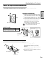
2. Loosely screw in the screws.
● Temporarily remove the base bracket from the wall and loosely screw in 2 off-the-shelf screws in the screw
hole positions marked on the wall. At this time, the screw heads should extend several millimeters above
the wall so that the base bracket can be hung on the screw heads.
● Hang the base bracket on the installed screws, check to make sure the bracket is not sagging to the left or
right, and then firmly tighten the screws. Use off-the-shelf screws to secure the remaining screw holes (14 to
18 screws).
Min. 4mm
Wall
A
B
Use the weight with the
string used in Step 1 to
make sure the bracket
is perpendicular.
Base bracket
US
24
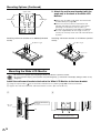
Mounting Options (Continued)
Setting the angle of the wall-mount bracket
■ The wall-mount bracket is assembled for perpendicular installation, so to use it for tilted installation,
please follow the procedure below to set it at the installation angle.
Connection
and Installation
Setting the installation angle.
1 Remove the 2 vertical installation screws. These
screws are used when setting the angle in step
3.
2 Assemble the wall-mount bracket as desired as
shown in the figure. (Figure shows a 20˚ angle.)
3 Use the screws removed in Step 1 (M6 15 mm
length × 2 screws) and the included screws M6
15 mm length × 2 screws to loosely fasten the
angle-setup bracket with 4 screws. Firmly
tighten these 4 screws after the angle-setup
bracket position has been determined.
Wall-mount bracket
Caution
Installation angle:
• When setting the angle of the wall-mount bracket,
be careful not to pinch your fingers, etc.
Screws M6 15mm length (4 screws)
LC-M3700 (Horizontal mount) 0° to 20°
LC-M3710 (Vertical mount)
0°
As the screw hole numbers become larger
(5, 10,15, 20), the Wide LCD Monitor will be
tipped farther forward.
20˚
15˚
10˚
5˚
Install so that the
angle-setup bracket
spacers are facing
inward.
Wall-mount bracket
Angle setup bracket (2 units)
Attaching wall-mount bracket to the monitor
Terminal cover
1. Detach the temporary stand.
Screws
(4 locations)
Wide LCD Monitor
●Place the monitor (face down) on a table, etc.
covered by a thick, soft cloth for LCD panel
protection.
●Position the monitor near the edge of the table so
that the temporary stand does not hit the table, then
remove the terminal cover.
●Unfasten the 4 screws used to secure the
temporary stand in place.
Temporary stand
Table
Soft cloth, etc.
25
US
Mounting Options (Continued)
2. Attach the wall-mount bracket (with the
angle set) to the back of the Wide LCD
Monitor.
Upper side
Marking A
●Make sure all cables and cords are connected
and bundled (see page 29).
●Attach the terminal cover to the back of the
monitor and align the wall-mount screw holes
(Marking A: 4 locations) with the holes (4
locations) on the back of the Wide LCD Monitor.
●Use the supplied M6 30 mm length screws (4
screws) to securely fasten the wall-mount bracket
in place.
Marking A
Wall-mount bracket
Attaching wall-mount bracket to LC-M3700 (horizontal
mount)
Attaching wall-mount bracket to LC-M3710 (vertical
mount)
M6 30mm length
M6 30mm length
Upper side
Mounting the Wide LCD Monitor
Caution
• Be sure to use 2 people when installing the Wide LCD Monitor to the base bracket.
• Be sure to perform Steps Å and ı below. Just performing Step Å could result in the display falling off, which is very
dangerous.
Install the wall-mount bracket attached to the Wide LCD Monitor to the base bracket.
Å Hang the square holes ( ) of the wall-mount bracket on the hooks (page 24) of the base bracket.
ı Tighten the wall-mount bracket and base bracket screws. (Be sure to do this.)
Å
ı
Make sure the hooks are
engaged.
Wide LCD
Monitor
Wall
Tighten from the bottom.
M5 screws 8mm length (2 screws)
Base bracket
US
26
Mounting Options (Continued)
Outside dimensional drawings
»With table stand attached
Unit: inch [mm]
35-25/32 [909]
4-17/64
[108.4]
3-29/32
[99.5]
11-13/32 [290]
3-15/64
[82.1]
Connection
and Installation
2-5/16
[58.8]
31-57/64 [810]
18-43/64 [474.5]
37-23/64
[949]
1-13/32
[36]
32-11/32 [821.6]
33
/64
[13]
30/64 [12]
15
5/16
[18.5]
[290]
2-3/16 3-11/64
[55.5] [80.5]
11-13/32
2-39/64 [66.1]
4-1/8 [105]
6-3/32 [155]
10-7/16 [265]
7-7/8 [200]
7-7/8 [200]
2-39/64 [66.1]
6-1/16
[154]
1-1/2 [38.5]
4-17/32[115]
5-19/32 [142]
2-27/32[72.5]
6-11/16 [170]
7-7/8
[200]
14-9/16 [370]
23/32
6-27/32 [173.8]
[65]
3-28/32
[98.4]
2-9/16
6-27/32 [173.8]
[8]
/16
[24]
33
/64
/64
[13]
[12.3] 29
1- /64[37]
31
8-25/32 [223]
1/4
[6.5]
22-33/64 [572]
14-5/32 [356]
25-17/64 [642]
18-7/32 [462.8]
with the
door opened
1-31/32 [50]
4-23/32 [120]
6-19/64 [160]
7-13/32 [188.3]
13-7/32 [335.8]
27
US
Mounting Options (Continued)
Outside dimensional drawings
»With wall-mount bracket attached
Unit: inch [mm]
3
1- /16 [30]
5-3/32 [129.5]
6-4/3 [171.7782]
9-15/16 [252.5]
8-3/8 [212.9]
15°
10°
20°
22-33/64 [572]
5°
11-7/16 [290.4]
5-3/32 [129.5]
(0°)
4-13/16 [122.3]
(5°)
4-1/2 [114.2]
4-5/32 [105.5]
(15°)
(10°)
3-25/32 [96]
(20°)
LC-M3700 (Horizontal mount)
Panel center
5-3/32 [129.5]
19
37-23/64 [949]
1-3/16 [30]
5-3/32 [129.5]
(0°)
LC-M3710 (Vertical mount)
US
28
Wall-mount bracket center
/32 [15]
Bundling Cables
■ Cables and cords connected to the back of the monitor can be bundled using the supplied
cable clamp and cable binders. This will prevent stray or disorganized cables at the back of
the monitor.
"Rear view
Connection
and Installation
To external devices
Cable binder
Wrap the cable binder
around the bundle of
cables.
Put the thinner end of
cable binder through
the hole as shown, and
tighten appropriately.
Bundle of cables
"With terminal cover closed
Cable binder
Wrap the cable binder
around the bundle of
cables.
Put the thinner end of
cable binder through
the hole as shown, and
tighten appropriately.
Bundle of cables
To external devices
How to use the supplied terminal cover mounting screws and flat washers
» Use terminal cover mounting screws to firmly fix the terminal cover if difficult to close after
bundling the cables.
29
US
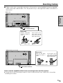
Turning on Power
■ Before turning on POWER, make sure that peripherals, external speakers, and the AC cord
are connected properly.
■ There are two power supply switches: POWER (main power supply) and STANDBY/ON.
Main POWER switch
"Rear view
"Front view
STANDBY/ON
indicator
"POWER (main) switch
PRESS POWER (MAIN) ON THE
BACK OF THE MONITOR.
» The STANDBY/ON indicator at the lowerright corner of LCD panel lights up green.
■ Please note that STANDBY/ON will not turn power on if the main POWER is not switched ON.
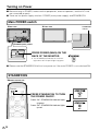
STANDBY/ON
"Remote control unit
STANDBY/ON
INPUT
VOL
RETURN
MENU
Power “On”: STANDBY/ON indicator lights
up green.
Power “Off”: STANDBY/ON indicator lights
up red.
ENTER
ENLARGE
US
30
PRESS STANDBY/ON TO TURN
THE POWER ON/OFF.
WIDE
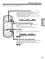
Remote Control Unit
■ Generally the monitor is operated using the remote control unit once main POWER on the
back of the monitor has been turned on.
INPUT (Input selection)
Press INPUT to display the input selection screen. Press INPUT or
use '/" (Cursor control) to select the input mode.
» In INPUT1 or PC mode, the video selected in “Input Select”
(page 54) is displayed on the screen.
» INPUT2 can be selected only when it has been set to “Input” in
“INPUT2 Select” (see page 56).
STANDBY/ON
INPUT1
VOL
RETURN
MENU
INPUT3
PC
Basic Operation
INPUT
INPUT2
VOL (Volume adjustment)
Press
to increase the volume, and
to decrease the
volume.
Sound is muted when volume is set to “0”.
Each input terminal has its own volume output setting.
ENTER
ENLARGE
WIDE
ENLARGE
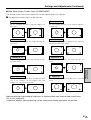
The display toggles as shown below, based on the setting on the
menu screen.
LCD MONITOR
2×2
Off
56
61
3×3
Enlarge
WIDE (Screen size selection)
Press WIDE to display the “Wide Mode” menu screen. Press WIDE
or use '/" (Cursor control) to select the screen size.
The screen sizes which can be selected vary depending on the
type of video signal.
57
62
31
US
Menu Items
■ Menus can be displayed on the screen to enable video and audio adjustment, and setting of
various functions, using the remote control. For details refer to the pages where each topic is
explained.
Menu option selection
Buttons used in menu operation
MENU
» Displays and turns off the menu screen.
STANDBY/ON
INPUT
VOL
RETURN
MENU
UP/DOWN/LEFT/RIGHT (Cursor control)
» '/"/\ / |: Selects a desired item on the screen.
» \ / |: Adjusts a selected item.
ENTER
Pressing
increases a numerical value.
Pressing
decreases a numerical value.
ENTER
» Continues to next step.
» Determines the selected item.
ENLARGE
WIDE
RETURN
» Returns to the previous menu screen.
LCD MONITOR
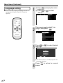
Example of menu operation: Adjusting “Position” in “Setup”.
1
MENU
Press
and the
menu screen displays.
2
Press
(or
select “Setup”.
) to
3
Press
(or
) to
select “Position”, and
ENTER
then press
.
MENU [Picture]
Picture
Audio
Power control
1
Contrast
[30]
0
+40
Black level
[ 0] –30
+30
Color
[ 0] –30
+30
Tint
[ 0] –30
+30
Sharpness
[ 0] –30
+10
Advanced
Reset
Power control
Setup
Option
Input Select
Power control
Setup
Option
Control Lock
Control Lock
[AV]
Input Select
[AV]
Position
Position
Picture Flip
[Normal]
Picture Flip
[Normal]
Language
[English]
Language
[English]
Input 2 Select
[Input]
Input 2 Select
ID No. Setting
[—]
ID No. Setting
Enlarge
Panel Protection Cover
[Off]
[Detached]
Enlarge
Panel Protection Cover
[Input]
[—]
[Off]
[Detached]
∫ The position menu screen is
displayed.
» Due to the type of signal and its frequency, the items in the menu screen appear differently.
NOTE:
US
32
Menu Items (Continued)
Menu screen explanation
"Menu screen example (partial)
Power control
Setup
Option
Control Lock
Input Select
Item displayed in yellow
[AV]
Position
Picture Flip
[Normal]
Language
[English]
Input 2 Select
[Input]
ID No. Setting
[—]
Enlarge
Panel Protection Cover
[Off]
[Detached]
» This indicates item currently selected.
» Press ENTER to go to the adjustment screen for
this item.
Item in brackets
» This shows the current setting for the item.
Basic Operation
Items displayed in white
» This indicates that an item can be selected.
Item displayed with gray characters
Operation guide
» These items cannot be selected.
∗ There are various reasons why items cannot be
selected, but the main reasons are as follows:
1. There is no signal.
2. The function is not compatible with the
current input signal.
Most picture adjustment options cannot be
selected in the following states:
1. When “Underscan” is selected in “Wide Mode”.
2. With a PC (digital) signal.
MENU [Setup···Picture Flip]
Set Picture Direction
Normal
Mirror
Upside Down
Rotate
: Select/
RETURN
: Back
MENU
: Exit
This shows the remote control buttons which
can be used with the currently displayed screen,
and their functions.
» Operate by following this operation guide.
Menu screen duration
» The menu screen will revert to the normal screen if there is no operation for 1 minute while the menu
screen is displayed.
Language setting
» The On-Screen Display language can be set to Japanese, English, German, French or Spanish.
See page 36 for details.
» Menu options differ between the AV and PC modes, but operating procedures are the same.
NOTE: » The menu item illustrations in this operation manual are for explanation purposes (some are enlarged; others
cropped) and may vary slightly from the actual displays.
33
US
Menu Items (Continued)
PC (analog) input mode menu items
INPUT3 : RGB
PC : Analog
PC : Digital
For a table of adjustment ranges for each menu item, please see Appendix3 on
page 70.
Picture
51
Contrast/Black Level
Audio
51
Advanced
Power control
Setup
C.M.S. (H)/(S)/(V)
52
Red/Green/Blue
53
Treble/Bass/Balance
53
Brightness
53
Power Management
54
Lock Item
Option
54
Control Lock
54
Input Select
Menu Display/Remote/Buttons/Power/
54
Input Signal
RS-232C
54
Auto Sync.
55
Fine Sync.
56
Picture Flip
36
Language
56
INPUT2 Select
56
ID No. Setting
56
Enlarge
56
Panel Protection Cover
54
PIN/PIN Clear
54
Start Now/When Connected
55
H-Pos./V-Pos./Clock/Phase
57
Wide Mode/DNR/Quick Shoot/
Monitor Speaker Output
» Due to the type of signal and its frequency, some items are not selectable and grayed out.
NOTE: » “C.M.S.” is the only picture adjustment item which can be used with PC (digital) signals.
» “Fine Sync.” (position adjustment etc.) cannot be used with PC (digital) signals.
US
34
Menu Items (Continued)
AV input mode menu items
INPUT1: AV, Y/C
INPUT2:
INPUT3: COMPONENT
Picture
For a table of adjustment ranges for each menu item,
please see Appendix3 on page 71.
51
Audio
Contrast/Black Level/Color/Tint/
Sharpness/
Power control
51
Setup
Advanced
C.M.S. (H)/(S)/(V) /Color Temp/Black/
Option
3D-Y/C / Monochrome/Film Mode/
Basic Operation
I/P Setting
53
Treble/Bass/Balance
53
Brightness
53
Power Management
54
Lock Item
54
Control Lock
54
Input Select
Menu Display/Remote/Buttons/Power/
55
Position
RS-232C
56
Picture Flip
36
Language
56
INPUT2 Select
56
ID No. Setting
56
Enlarge
56
Panel Protection Cover
54
PIN/PIN Clear
55
H-Pos./V-Pos.
57
Wide Mode/Color System/
DNR/Quick Shoot/
Monitor Speaker Output
»“INPUT2 Select” is not displayed when the input mode is set to “INPUT2”.
»
Due to the type of signal and its frequency, some items are not selectable and grayed out.
NOTE:
» If “Underscan” has been selected in “Wide Mode”, most picture adjustment items cannot be used (except for
some settings in “Advanced”).
35
US
Menu Items (Continued)
Language setting
■ The On-Screen Display language can be set
to Japanese, English, German, French or
Spanish.
MENU
1
1 Press
to display the menu
screen.
2 Press
or
to select
“Setup”.
MENU [Setup]
Picture
Audio
Power control
Setup
Option
Control Lock
[AV]
Input Select
Position
Picture Flip
[Normal]
Language
[English]
[Input]
Input 2 Select
[—]
ID No. Setting
[Off]
Enlarge
Panel Protection Cover
[Detached]
STANDBY/ON
INPUT
VOL
RETURN
MENU
ENTER
ENLARGE
WIDE
2
Press
or
to select “Language”, then press ENTER .
Power control
Setup
Option
Control Lock
[AV]
Input Select
LCD MONITOR
Position
[Normal]
Picture Flip
[English]
Language
[Input]
Input 2 Select
[—]
ID No.Setting
Enlarge
[Off]
Panel Protection Cover
3
Press
or
language.
[Detached]
to select desired
MENU [
MENU [Setup···Language]
Display language settings.
English
Deutsch
Français
Español
:Select /
RETURN
:Back
MENU
:Exit
»The menu screen is now displayed in the
language selected.
4
US
36
Press
screen.
MENU
to return to normal
PC Operation
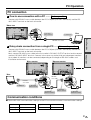
PC connection
1 One-to-one connection with a PC ....... Basic operation
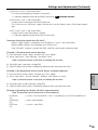
Connect with RS-232C cross cable between the PC COM port (RS-232C connector) and the RS232C INPUT terminal on the back of monitor.
"Rear view
To RS-232C
INPUT terminal
To COM port
"PC
Basic Operation
RS-232C cross cable
2 Daisy chain connection from a single PC....... Advanced operation
"First monitor
PC Operation
Connect with RS-232C cross cable between the PC COM port (RS-232C connector) and the RS232C INPUT terminal on the back of monitor.
Next, connect RS-232C cross cable to the first monitor’s RS-232C OUTPUT terminal and to second
monitor’s RS-232C INPUT terminal. Connect in the same way to the third and subsequent monitors.
Up to about 20 monitors can be connected, depending on the length of RS-232C cables and
installation environment.
"Second monitor
"PC
RS-232C
cross cable
RS-232C
cross cable
To COM port
To RS-232C
INPUT terminal
To RS-232C
OUTPUT terminal
To RS-232C
INPUT terminal
To RS-232C
OUTPUT terminal
Communication conditions
■ Set the RS-232C communication settings on the PC to match the monitor’s communication settings.
Baud rate:
9,600 bps
Stop bit:
1 bit
Data length:
8 bits
Flow control:
None
Parity bit:
None
37
US
PC Operation (Continued)
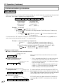
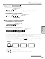
Communication procedure
Basic operation
<Command format>
When a command is sent from the PC to the monitor, the monitor operates according to the received
command, and sends a response message to the PC.
Carriage return code
C1
C2
C3
C4
P1
P2
P3
P4
↵
Parameter field
(4 character string
comprised of:
0-9, +, –, space, ?)
Command field
(4 prescribed
alphanumerical
characters)
Example: VOLM0030
POWR
1 (“ ” indicates a space.)
* Be sure to input 4 characters for the parameter. Pad with spaces if necessary.
× VOLM30
䡩 VOLM
30( ) (“ ” indicates a space, “ ” is the carriage return code
(0DH, 0AH or 0DH).)
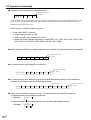
If a command has “R” listed for “Direction” in the “RS-232C Command table” on page 46, the current value can be returned by using “?” as the parameter.
Example: 1If an ID number has not been set:
VOLM????
←From PC to monitor (current volume setting: ?)
30
←From monitor to PC (current volume setting: 30)
2If an ID number has been assigned (For example, ID number = 001)
VOLM
? ←PC to monitor (“ ” indicates a space)
30 001
←Monitor to PC (“ ” indicates a space)
<Response code format>
■ When a command has been executed correctly
Carriage return code
(0DH, 0AH)
O
K
This is returned when execution of the command is
finished.
↵
■ When a command has not
been executed correctly*
Carriage return code
(0DH, 0AH)
E
R
R
↵
■ If execution of the command is
Carriage return
taking some time
code (0DH, 0AH)
W
A
I
T
↵
* This is returned when there is no such command,
or when the command cannot be used in the
current state of the monitor (i.e. video auto-adjustment with video display).
* If there is a bad connection between the PC and
monitor, or if communication has not been established, nothing is returned (not even ERR).
If a command takes some time to execute, WAIT may
be returned as the return value. Wait for a moment, and
OK or ERR will be returned. New commands cannot be
received during this time, even if they are sent.
■ If RS-232C is locked
Carriage return code
(0DH, 0AH)
L
US
38
O
C
K
E
D
↵
If RS-232C control has been locked with Control lock
(see page 54), LOCKED is returned as the returned
value.
PC Operation (Continued)
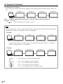
Advanced operation
■ This section explains commands for daisy chain connection. The basic communication procedure is
the same as in the “Basic operation” section.
<ID numbers>
You can assign a unique ID number to each monitor (see page 56). This allows you to control a
particular monitor in a daisy chain of monitors.
Up to about 20 monitors can be connected, depending on the length of RS-232C cables and
installation environment.
You can assign ID numbers either from the menu screen (via remote control or the control buttons on
the monitor) or from the PC using RS-232C cable.
[Example]
PC
ID number: 1
ID number: 2
ID number: 3
ID number: 4
If monitors are connected as shown above, you can execute commands like “Set the volume of the
monitor with ID 4 to 20”.
PC Operation
When controlling monitors linked in a daisy chain by designating ID numbers, you should basically
avoid any duplication of ID numbers.
If the same ID number is assigned to multiple monitors, only the monitor closest to the PC can be
controlled with that ID number.
If monitors are connected as shown below, only the monitor 1 can be accessed with ID number 2.
Monitor 2 cannot be controlled using that ID number.
[Example]
PC
ID number: 1
ID number: 2
ID number: 2
①
②
ID number: 3
ID numbers do not have to be assigned in ascending order starting from the PC. They can also be
connected as shown below.
[Example]
PC
ID number: 3
ID number: 2
ID number: 4
ID number: 1
Continued on the next page.
39
US
PC Operation (Continued)
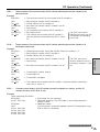
<Commands for ID control>
The command examples shown on this page assume the following connection and ID number set
up.
PC
ID number: 1
ID number: 2
ID number: 3
ID number: 4
IDST······A monitor receiving this command sets its own ID number in the parameter field.
Example: IDST0001
OK 001 ←The ID number of this monitor is set to 1.
Note
After linking monitors, you can automatically assign ID numbers by using the IDST command with
the Repeater control (see “Repeater control” on page 42).
[Example]
PC
Set 1
Set 2
Set 3
Set 4
If you connect monitors as shown above, and use the command “IDST001+”, ID numbers
will be set automatically, as shown below.
[Example]
PC
IDST001+
WAIT
OK 001
OK 002
OK 003
OK 004
US
40
ID number: 1
ID number: 2
ID number: 3
←ID setting command with repeater control
←ID = “OK” response from ID number=1
←ID = “OK” response from ID number=2
←ID = “OK” response from ID number=3
←ID = “OK” response from ID number=4 (End)
ID number: 4
PC Operation (Continued)
IDSL······ The parameter of this command sets the ID number indicating the monitor subject to the
next command.
Example:
IDSL0002
← The next command is for the monitor with ID number=2.
WAIT
← Searching for monitor with ID number=2.
OK 002
← Found monitor with ID number=2
VOLM0030
← Set volume of monitor with ID number=2 to 30
WAIT
← Processing
OK 002
← OK response from monitor with ID number=2
The IDSL command is
VOLM0020
← Set volume to 20
effective only once, for the
OK 001
← The volume of the monitor with ID number=1
immediately succeeding
(the one directly connected to the PC) is set to
command.
20.
WAIT
OK 002
IDLK0000
WAIT
OK 002
VOLM0010
OK 001
PC Operation
IDLK······ The parameter of this command sets the ID number indicating the monitor subject to all
subsequent commands.
Example:
IDLK0002
← Following commands are for the monitor whose ID number is “2”.
WAIT
← Searching for monitor with ID number=2.
OK 002
← Found monitor with ID number=2
VOLM0030
← Set volume of monitor with ID number=2 to 30
The IDLK command
WAIT
← Processing
remains effective until it is
OK 002
canceled, or power is shut
off.
VOLM0020
← Set volume of monitor with ID number=2 to 20
← Canceling ID number setting
← Canceling IDLK
← Cancelation complete
← The volume of the monitor with ID number=1 (the one directly connected
to the PC) is set to 10.
IDCK······ Provides screen display of the ID number currently assigned to a monitor, and the ID
number currently set for IDLK (if any).
Example:
(After executing IDLK0002)
IDCK0000
← (Parameter has no meaning)
ID:001 IDLK:002
← Returned response. The ID number is also displayed on the
monitor screen.
IDCK000+
← Repeater control
WAIT
(If a command is used with repeater control, ID designation using
ID:001 IDLK:002
IDSL or IDLK is canceled.)
ID:002 IDLK:002
ID:003 IDLK:002
ID:004 IDLK:002
Continued on the next page.
41
US
PC Operation (Continued)
<Repeater control>
This system has a function to allow setting of multiple monitors connected in a daisy chain using a
single command. This function is called repeater control.
Up to about 20 monitors can be connected, depending on the length of RS-232C cables and
installation environment.
You can use Repeater control function without assigning ID numbers.
[Example]
PC
Set 1
Set 2
Set 3
Set 4
If monitors are connected as shown above, you can execute a command like “Set all
monitors’ input settings to INPUT”.
<Repeater control command>
Repeater control is achieved by setting the FOURTH CHARACTER of the parameter to “+”.
Example: VOLM030+
← Sets volume of all monitors to 30.
In repeater control, responses are returned by all the connected monitors.*
If you want to determine that a value has been returned by a specific set, assign ID numbers to
each monitor in advance.
If no response is returned, this may be because the monitor has not received (or is still processing) the command, so it is possible that new commands may not be executed even if they
are sent.
* If power is turned “OFF” using Repeater control, only the monitor closest to the PC returns a
response.
Example: (When 4 monitors are connected, and assigned ID numbers 1 through 4)
VOLM030+
WAIT
OK 001
OK 002
OK 003
OK 004
← If 4 monitors are connected in a chain, reliable operation can be ensured
by sending a new command only after a reply has been returned by 4th
(last) monitor.
Repeater control can also be used for reading settings.
Example:
VOLM???+
WAIT
10 001
20 002
Volume settings for all monitors are returned.
30 003
40 004
» If repeater control is used during ID designation (IDSL, IDLK), the ID designation is canceled.
NOTE:
US
42
PC Operation (Continued)
<Response format in Advanced operation >
■ Normal response
1Response when no ID number has been set.
Carriage return code
(0DH, 0AH)
O
K
A response is returned when execution of the
pertinent command is finished.
↵
2Response when an ID number has been set.
Space (20H)
O
K
SPC
0
0
Carriage return code
(0DH, 0AH)
1
↵
ID number of
responding monitor
■ When a command has not been executed correctly*
1Response when no ID number has been set.
Carriage return code
(0DH, 0AH)
E
R
R
↵
PC Operation
2Response when an ID number has been set.
Space (20H)
E
R
R
SPC
0
0
Carriage return code
(0DH, 0AH)
1
↵
ID number
* This is returned when there is no such command, or when the command cannot be used in the
current state of the monitor (i.e. video auto-adjustment with video display).
* If communication has not been established for reasons like a bad connection with the monitor,
nothing is returned (not even ERR).
* If no monitor has been assigned the designated ID number (e.g. if the command IDSL0002[X] is
issued, but no monitor with ID=002 is found), ERR XXX[X] is returned.
(ID number at the furthest end)
[Example]
PC
Set 1
Set 2
Set 3
In the above case
IDSL0004
←Non-existent ID number
WAIT
ERR 003
←Monitor with ID=3 at the furthest end returns ERR
Continued on the next page.
43
US
PC Operation (Continued)
■ If execution of the command is taking some time.
Carriage return code
(0DH, 0AH)
W
A
I
↵
T
If execution of a command takes some time, WAIT may be returned as the returned value. In this
case, a value will be returned if you wait a while. During this time, new commands will not be
received, even if they are sent.
No ID number is attached to WAIT response.
• Cases where WAIT is returned
1. When repeater control is used
2. When an IDSL or IDLK command is used
3. When one of the following commands is used: RSET, INP1, INP2, INP3, INPC, INPS, ITGD,
IAVD, IPCD, CLSY, ASNC, WIDE, EMAG, EPOS, PXSL, POWR
■ When control via RS-232C is locked (to prevent use) using the Control lock function (see page 54).
Carriage return code
(0DH, 0AH)
L
O
C
K
E
D
↵
■ If a timeout occurs while waiting for a command
T
I
M
E
O
U
T
↵
Carriage return code
(0DH, 0AH)
■ If a timeout occurs while waiting for a command (when the monitor waiting for the command is
assigned an ID number = 001 in the following example)
Space (20H)
T
I
M
E
O
U
T
SPC
0
0
1
↵
Carriage return code
(0DH, 0AH)
■ If the current parameter is read out using "?" for the parameter (for numerical values etc.)
1Response when no ID number has been set.
<Example> VOLM????
10
2Response when an ID number has been set. (In the example below: ID=001)
<Example> VOLM????
10 001
US
44
PC Operation (Continued)
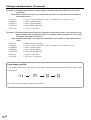
<Communication interval>
If the next command is sent in the interval before OK or ERR is returned, it will basically be ignored.
(Exception: Forced end using ASNC command)
Leave an interval of 100 ms between command response and transmission of the next command.
You can use Repeater control function without assigning ID numbers.
VOLM0020
OK
Leave an interval of 100 ms
INP10000
OK
PC Operation
45
US
PC Operation (Continued)
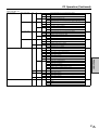
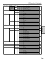
RS-232C command table
<How to read the command table>
Command :
38
Direction :
W
When the “Parameter” is set in the parameter field ( 38 ), the
command functions as described under “Control/Response Contents”.
R
The returned value indicated under “Reply” can be obtained by setting
“????”, “___?” or “???+” (repeater control) in the parameter field ( 38 ).
38
Parameter :
Command field
Parameter
Response
Reply :
Returned value
∗A circle indicates commands which can be used in power standby mode.
Power control, etc.
CONTROL ITEM
POWER SETTING
Command
POWR
Direction
W
Parameter
Switches to standby.
1
R
Returns from standby.
0
Standby state
1
Normal status
2
Power standby state ("Mode2" in "Power Management").
CHANNEL DISPLAY
DISP
W
−
VOLUME
VOLM
WR
0 - 60
0 - 60
MUTE
MUTE
WR
0
0
OFF
1
1
ON
SYNC CHECK
SYNC
CAUSE OF LAST STANDBY
STCA
W
W
It displays channel display.
0
It returns Yes/No.
1
It returns frequency.
0
R
Content initialization
0
No standby operation (except remote control and monitor button operation) after
initialization
1
Electrical standby due to some error condition (See cause of last error)
2
Invalid input has continued for a long time during PC display
3
It entered standby mode (PC mode: "Mode1" in "Power Management")
4
It entered standby mode (PC mode: "Mode2" in "Power Management")
6
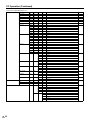
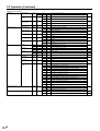
CAUSE OF LAST ERROR
POWER CONTROL
LANGUAGE
RESET
US
CONTROL/RESPONSE CONTENTS
Reply
0
46
ERCA
WR
BRIGHTNESS
VLMP
WR
POWER
PMNG
WR
LANG
WR
0
±8
It entered standby mode by the command from RS-232C.
Content initialization
0
No detectable error has occurred
1
Invalid input has continued for a long time during PC display
2
Internal bus error
3
Abnormal temperature
4
Board connection error
5
Lamp error
7
Electrical system error
8
Error in communication with microcomputer
±8
Brightness
0
0
Off
1
1
Mode1
2
2
Mode2
1
German
2
French
4
Spanish
13
Japanese
14
English
RSET
W
4 digits
Input 4-digit PIN for parameter. It resets to factory preset value.
RSE+
W
4 digits
Input 4-digit PIN for parameter. It resets to factory preset value. For Repeater
control
∗
PC Operation (Continued)
Input selection, etc.
INPUT SELECTION
INPUT1 SELECTION
INP1
W
0
Leaves input selection as is, and switches input to INPUT1
1
Sets input selection for INPUT1 to "AV"
2
R
INPUT2 SELECTION
INP2
W
Sets input selection for INPUT1 to "Y/C"
1
Input selection for INPUT1 is "AV"
2
Input selection for INPUT1 is "Y/C"
0
Leaves input selection as is, and switches input to INPUT2. ERR if INPUT is set to
output.
1
Sets INPUT2 selection to "Input"
9
R
INPUT3 SELECTION
INP3
W
Sets INPUT2 selection to "Output"
1
INPUT2 selection is "Input"
9
INPUT2 selection is "Output"
0
Leaves input selection as is, and switches input to INPUT3
1
Sets input selection for INPUT3 to "COMPONENT"
2
R
PC INPUT SELECTION
INPC
W
Sets input selection for INPUT3 to "RGB"
1
Input selection for INPUT3 is "COMPONENT"
2
Input selection for INPUT3 is "RGB"
0
Leaves input selection as is, and switches input to PC
1
Sets input selection for PC to "Analog"
2
INPC
INPUT SELECT
INPS
R
W
Sets input selection for PC to "Digital"
1
Input selection for PC is "Analog"
2
Input selection for PC is "Digital"
0
Toggle operation
1
Switches input to video terminal of INPUT1.
2
Switches input to S-video terminal of INPUT1.
4
Switches input to video terminal of INPUT2. (Returns ERR if set to output.)
5
Switches input to INPUT3.
6
Switches input to D-sub pin 15 terminal of PC
7
INPUT SOURCE DISPLAY
Switches input to DVI terminal of PC
1
Displays video signal from INPUT1
2
Displays S-terminal input video from INPUT1
4
Displays video from INPUT2
5
Displays INPUT3
6
Displays D-sub pin 15 terminal input video from PC
7
Displays DVI terminal input video from PC
ITGD
W
0
Toggle operation
IAVD
W
1
Switches input to INPUT1.
2
Switches input to INPUT2. (Return ERR if set to output.)
3
Switches input to INPUT3.
IPCD
W
IMOD
R
−
PC Operation
R
Switches input to PC.
1
INPUT1
2
INPUT2
3
INPUT3
5
PC
47
US
PC Operation (Continued)
Picture and audio adjustment, etc.
PICTURE ADJUSTMENT
CONTRAST
CONT
WR
0 - 40
0 - 40
BLACK LEVEL
BLVL
WR
±30
±30
±30
COLOR
COLR
WR
±30
TINT
TINT
WR
±30
±30
SHARPNESS
SHRP
WR
±10
±10
RED
REDG
WR
±30
±30
GREEN
GREN
WR
±30
±30
BLUE
BLUE
WR
±30
±30
C. M. S. (H)
CMHR
WR
±30
±30
Red
CMHY
WR
±30
±30
Yellow
CMHG
WR
±30
±30
Green
CMHC
WR
±30
±30
Cyan
CMHB
WR
±30
±30
Blue
CMHM
WR
±30
±30
Magenta
CMSR
WR
±30
±30
Red
CMSY
WR
±30
±30
Yellow
CMSG
WR
±30
±30
Green
CMSC
WR
±30
±30
Cyan
CMSB
WR
±30
±30
Blue
CMSM
WR
±30
±30
Magenta
CMVR
WR
±30
±30
Red
CMVY
WR
±30
±30
Yellow
CMVG
WR
±30
±30
Green
CMVC
WR
±30
±30
Cyan
CMVB
WR
±30
±30
Blue
CMVM
WR
±30
±30
Magenta
CTMP
WR
0
0
Low
1
1
Mid-Low
2
2
Mid
3
3
Mid-High
4
4
High
0
0
Off
1
1
High
2
2
Low
0
0
Standard
1
1
Fast
2
2
Slow
0
Off
C. M. S. (S)
C. M. S. (V)
COLOR TEMP
BLACK
3D-Y/C
AUDIO ADJUSTMENT
COLOR SYSTEM
BLAK
3DYC
WR
WR
MONOCHROME
MNCR
WR
0
1
1
On
FILM MODE
FILM
WR
0
0
Off
1
1
On
I/P SETTING
IPST
WR
0
0
Interlace
1
1
Progressive
TREBLE
TRBL
WR
±15
±15
BASS
BASS
WR
±15
±15
BALANCE
BLNC
WR
±30
±30
CLSY
W
0
AUTO
1
PAL
3
SECAM
4
NTSC358
5
R
US
48
NTSC443
0
AUTO
1
PAL
3
SECAM
4
NTSC358
5
NTSC443
PC Operation (Continued)
Picture and audio adjustment, etc. (continued)
POSITION/FINE SYNC.
H-POSITION (AV)
HPOS
H-POSITION (PC)
V-POSITION (AV)
VPOS
V-POSITION (PC)
WR
±10
±10
Video/S-video INPUT3 (Component)
WR
0 -180
0 - 180
INPUT3 (RGB)/PC (Analog)
WR
±20
±20
Video/S-video INPUT3 (Component)
WR
0 - 99
0 - 99
INPUT3 (RGB)/PC (Analog)
Returns ERR in case of a video signal
CLOCK
CLCK
WR
0 - 180
0 - 180
PHASE
PHSE
WR
0 - 40
0 - 40
ASNC
W
0
1
Start
ASAE
WR
0
Setting cancel
WIDE
WR
AUTO SYNC.
1
WIDE MODE
AV (Input1/Input2/Input3
(Component)
PC (Input3 (RGB)/PC)
PICTURE FLIP
PFLP
ENLARGE SETTING
ENLARGED IMAGE
EMAG
EPOS
WR
WR
WR
WR
POSITION
DNR
QUICK SHOOT
MONITOR SPEAKER OUTPUT
INPUT SIGNAL
DNR_
QSDV
MOSP
WR
WR
WR
PXCK
R
PXSL
WR
Automatic execution when PC sync is input
0
0
Toggle operation
1
1
Normal
2
2
Full 14:9
3
3
Zoom 14:9
4
4
Panorama
5
5
Cinema 14:9
6
6
Cinema 16:9
7
7
Full
8
8
Underscan
0
0
Toggle operation
1
1
Normal
2
2
Full
3
3
Cinema
4
4
D by D
0
0
Normal
1
1
Mirror
2
2
Upside Down
3
3
Rotate
0
0
Off
2×2
1
1
2
2
3×3
0
0
Enlarge Setting : Off
0
0
Enlarge Setting : 2x2) Upper left
1
1
Enlarge Setting : 2x2) Upper right
2
2
Enlarge Setting : 2x2) Lower left
3
3
Enlarge Setting : 2x2) Lower right
0
0
Enlarge Setting : 3x3) Upper left
1
1
Enlarge Setting : 3x3) Upper middle
2
2
Enlarge Setting : 3x3) Upper right
3
3
Enlarge Setting : 3x3) Middle left
4
4
Enlarge Setting : 3x3) Center
5
5
Enlarge Setting : 3x3) Middle right
6
6
Enlarge Setting : 3x3) Lower left
7
7
Enlarge Setting : 3x3) Lower middle
8
8
Enlarge Setting : 3x3) Lower right
0
0
Off
1
1
Low
2
2
High
0
0
Off
1
1
On
0
0
Fixed
1
1
Variable
−
Returns current resolution in the form xxx,xxx.
0
0
V=400, 640x400
1
1
V=400, 720x400
0
0
V=480, 640x480
2
2
V=480, 848x480
3
3
V=480, 852x480
0
0
V=768, 1024x768
1
1
V=768, 1280x768
2
2
V=768, 1366x768
PC Operation
ENLARGE
WIDE
Returns ERR in case of a video signal
Abort (after execution)
49
US
PC Operation (Continued)
Other control options
ID NUMBER
ID NO. SETTING
IDST
W
0 - 255
R
CONTROL LOCK
IDSL
W
1 - 255
Sets a monitor ID number. This ID number is only effective for the command
immediately after this command.
0
Clears the ID number if one has been designated.
ID NO. SETTING
(SUBSEQUENT)
IDLK
W
1 - 255
Sets a monitor ID number. This ID number is effective for the next and all
subsequent commands after this command.
ID CHECK
IDCK
W
MENU DISPLAY
LMNU
WR
CONTROL BUTTONS
POWER
RS232C
SET PIN
INPUT PIN
CLEAR PIN
POWER-ON METHOD, ETC. MAX VOLUME
FIX VOLUME
OSD SETTING
DISPLAY BOOT
LREM
LBTN
LPOW
LCOM
PANEL PROTECTION COVER
US
50
0
Clears the ID number if one has been designated.
−
Displays selected ID number and the monitor's own ID number on the screen.
Normal (Menu Display is available)
1
1
Menu Display is not available.
1
1
Disabled
1
1
Disabled
1
1
Disabled
1
1
WR
Normal (Operational)
WR
Normal (Operational)
WR
Normal (Operational)
WR
Normal (Operational)
Disabled
PSET
W
4 digits
Sets PIN (Activates lock function)
PSE+
W
4 digits
Sets PIN: for repeater control
PINP
W
4 digits
Input of set PIN (Temporary unlock)
PIN+
W
4 digits
Input of set PIN: for repeater control
PCLR
W
4 digits
Initializes PIN
PCL+
W
4 digits
Initializes PIN: for repeater control
MVOL
WR
1 - 60
1 - 60
FVOL
WR
0
0
Off
1
1
Fixes volume at a constant value
ODSP
FINP
WR
WR
OPTION
SOUND INPUT SELECT
It returns the monitor's ID number.
ID NO. SETTING
(ONCE)
REMOTE CONTROL
PIN
It sets the monitor's ID number.
0 - 255
SNDS
COVR
WR
WR
Maximum volume
volume limit.
limit.Only
Onlydisplays
displaysvolume
volumeininnumbers
numberswhen
when
other
than
Maximum
setset
to to
other
than
60.60.
0
0
Normal
1
1
No OSD is displayed.
0
0
Normal
1
1
Starts with INPUT1 + [AV] input selection
2
2
Starts with INPUT1 + [Y/C] input selection
4
4
Starts with INPUT2. Returns ERR if INPUT2 selection is "Output"
5
5
Starts with INPUT3.
6
6
Starts with PC + [Analog] input selection
7
7
Starts with PC + [Digital] input selection
11
11
Starts with INPUT1 + [AV] input selection, and remains fixed
12
12
Starts with INPUT1 + [Y/C] input selection, and remains fixed
14
14
Starts with INPUT2, and remains fixed. Returns ERR if INPUT2 selection is "Output".
15
15
Starts with INPUT3, and remains fixed
16
16
Starts with PC + [Analog] input selection, and remains fixed
17
17
Starts with PC + [Digital] input selection, and remains fixed
0
0
Normal
1
1
Uses INPUT1 audio as fixed source
2
2
Uses INPUT2 audio as fixed source
0
0
Detached
1
1
Attached
Settings and Adjustments
Picture
Contrast
Adjustable range
Default
+ direction
– direction
0 - 40
30
For more contrast
For less contrast
Black Level
Adjustable range
Default
+ direction
– direction
–30 - +30
0
Brightens entire video signal
Darkens entire video signal
Color (Video/S-video/COMPONENT)
Adjustable range
–30 - +30
Default
0
+ direction
For more color intensity
– direction
Decreases color intensity (Monochrome at “0”)
Tint (Video/S-video/COMPONENT)
Adjustable range
–30 - +30
Default
0
+ direction
Changes skin tone closer to green
– direction
Changes skin tone closer to magenta
Six-color hue adjustments
–30 - +30 (Red/Yellow/Green/Cyan/Blue/Magenta)
0
Move selected color hue clockwise
Move selected color hue counter-clockwise
Advanced: C. M. S. (S)
Function
Adjustable range
Default
+ direction
– direction
Six-color saturation adjustments
–30 - +30 (Red/Yellow/Green/Cyan/Blue/Magenta)
0
Increases saturation of the selected color
Decreases saturation of the selected color
Advanced: C. M. S. (V)
Function
Adjustable range
Default
+ direction
– direction
Six-color image value adjustments
–30 - +30 (Red/Yellow/Green/Cyan/Blue/Magenta)
0
Increases brightness of the selected image value
Decreases brightness of the selected image value
Settings and
Adjustments
Advanced: C. M. S. (H)
Function
Adjustable range
Default
+ direction
– direction
PC Operation
Sharpness (Video/S-video/COMPONENT)
Adjustable range
–10 - +10
Default
0
+ direction
For more sharpness
– direction
For less sharpness
51
US
Settings and Adjustments (Continued)
Advanced: Color Temp (Video/S-video/INPUT 3 COMPONENT)
Adjustable range
High, Mid-High, Mid, Mid-Low, Low
Default
Mid
Upward
Entire image bluish tone (color temperature increases)
Downward
Entire image reddish tone (color temperature decreases)
Advanced: Black (Video/S-video/INPUT 3 COMPONENT)
Adjustable range
Off, High, Low
Default
Low
Off
No Adjustment
High
For high detail in black portions
Low
For low detail in black portions
Advanced: 3D-Y/C (Video)
Adjustable range
Standard, Fast, Slow
Default
Standard
Standard
Normal adjustment [Sets characteristics for 3-dimensional Y/C separation to
standard setting.]
Fast
For movie image [Sets characteristics for 3-dimensional Y/C separation to settings
appropriate for movies.]
Slow
For still image [Sets characteristics for 3-dimensional Y/C separation to settings
appropriate for still pictures.]
Note:
Effective only when displaying video source with color system NTSC 3.58
Advanced: Monochrome (Video/S-video/INPUT 3 COMPONENT)
Adjustable range
On/Off
Default
Off
On
Displays video in monochrome. (“Tint” cannot be adjusted. The setting automatically
set to “Off” if “Color” is adjusted.)
Off
Normal color
Advanced: Film mode (Video/S-video/INPUT 3 COMPONENT)
Adjustable range
On/Off
Default
On
On
Automatically detects that the source signal is a video image at 24 frames/sec (DVDs
containing films etc.), and displays signal with high picture quality.
Off
Does not automatically detect sources at 24 frames/sec.
Note:
Effective only for interlaced video (480i/576i/1080i)
Advanced: I/P Setting (Video/S-video/INPUT 3 COMPONENT)
Adjustable range
Interlace/Progressive
Default
Progressive
Interlace
Displays interlaced signal with 2-dimensional interpolation
Progressive
Displays interlaced signal with 3-dimensional interpolation
Note:
Effective only for Video, S-video and COMPONENT 480i/576i image
Red (PC (analog)/INPUT3(RGB))
Adjustable range
–30 - +30
Default
0
+ direction
Brightens red component
– direction
Darkens red component
US
52
Settings and Adjustments (Continued)
Green (PC (analog)/INPUT3(RGB))
Adjustable range
–30 - +30
Default
0
+ direction
Brightens green component
– direction
Darkens green component
Blue (PC (analog)/INPUT3(RGB))
Adjustable range
–30 - +30
Default
0
+ direction
Brightens blue component
– direction
Darkens blue component
Audio
Treble
Adjustable range
Default
+ direction
– direction
–15 - +15
0
For stronger treble
For weaker treble
Bass
Adjustable range
Default
+ direction
– direction
–15 - +15
0
For stronger bass
For weaker bass
Balance
Adjustable range
Default
Toward left
Toward right
Left 30 - Right 30
0 (center value)
Decrease audio from the right speaker
Decrease audio from the left speaker
Power control
Power Management
Function
Adjustable range
Default
Off
Mode1
Mode2
Settings and
Adjustments
Brightness
Function
Adjustable range
Default
+ direction
– direction
Adjusts backlight brightness
–8 - +8
+8
Increases backlight brightness
Decreases backlight brightness
With this setting, the monitor automatically switches to (or returns from) the power
standby mode, depending on the presence of a sync signal.
Off/Mode1/Mode2
Off
No Power Management
Detects sync signal of currently displayed video signal, and enters power standby
mode if there is no sync signal for 8 minutes.
Detects sync signal of currently displayed video signal, and enters power standby
mode if there is no sync signal for 8 seconds. Restarts when sync signal is input again.
» The monitor may not work properly if the AC cord is unplugged and replugged when “Mode2” is selected in
“Power Management”. In this case simply press the STANDBY/ON button on the monitor or on the remote
NOTE:
control.
53
US
Settings and Adjustments (Continued)
Setup
Control Lock: Lock Item (See page 58 for details.)
Function
Adjustable range
Lock/Unlock (“Menu Display”, “Remote”, “Buttons”, “Power” and “RS-232C”)
Default
Unlock (all items)
Lock
The pertinent function is disabled when a PIN is set (see page 58).
Unlock
The pertinent function can be used, even if a PIN is set.
Control Lock: PIN (See page 58 for details.)
Function
Sets 4-digit PIN
After a PIN has been set, it becomes effective when the menu is closed.
If a PIN is temporarily canceled (see page 58 for details), it remains canceled until
the monitor enters standby mode or shuts down.
Control Lock: PIN Clear (See page 58 for details.)
Function
Initializes set PIN. (Returns to state where no PIN has been input.)
Input Select
Function
Adjustable range
Default
Selects video input terminal/type.
INPUT1: AV / Y/C
INPUT3: COMPONENT/RGB
PC: Analog/Digital
INPUT1: AV
INPUT3: COMPONENT
PC: Analog
Input Signal (INPUT3 (RGB) /(PC (analog))
Function
Manually selects input resolution.
Adjustable range
(Analog 400 vertical lines) 640 × 400/720 × 400
(Analog 480 vertical lines) 640 × 480/848 × 480/852 × 480
(Analog 768 vertical lines) 1024 × 768/1280 × 768/1366 × 768
(Digital 480 vertical lines) 640 × 480/480p
Default
(Analog 400 vertical lines) 640 × 400
(Analog 480 vertical lines) 640 × 480
(Analog 768 vertical lines) 1024 × 768
(Digital 480 vertical lines) 640 × 480
Auto Sync.: When Connected (INPUT3 (RGB) /(PC (analog))
Function
Automatically optimizes position, phase and clock when applicable video is input.
Adjustable range
Yes/No
Default
No
Note:
You can quickly achieve high-picture quality results by using a signal suited to the
adjustment as the video signal used for adjustment. Conversely, performing
adjustment with a signal unsuited for adjustment may cause adjustment to fail, or
make it impossible to achieve good results even if it succeeds.
Example of the ideal signal for use in adjustment: An image with full size and
resolution, and a vertical stripe signal which inverts between black and white at each
pixel.
*Signals suitable for Auto Sync.
•Detailed still image with well-defined contrast
•Image with high luminosity at edges
*Signals not suited for Auto Sync. •Image with low contrast
• Moving picture
•Image with low luminosity at edges
US
54
Settings and Adjustments (Continued)
Auto Sync.: Start Now
Function
Adjustable range
If “Yes” is selected and the ENTER button is pressed when applicable video is input,
the system automatically optimizes position, phase and clock using the video signal
which is currently being input.
Yes/No (“No” is always the default value)
Position: H-pos. (Video/S-video/INPUT 3 COMPONENT)
Adjustable range
–10 - +10
Default
0
+ direction
Image shifts right.
– direction
Image shifts left.
Position: V-pos. (Video/S-video/INPUT 3 COMPONENT)
Adjustable range
–20 - +20
Default
0
+ direction
Image shifts up.
– direction
Image shifts down.
Fine Sync.: H-pos. (INPUT3 (RGB)/(PC (analog))
Adjustable range
0 - 180
Default
0
+ direction
Image shifts right.
– direction
Image shifts left.
Note:
No position adjustment is available when PC (digital) signal is received.
Fine Sync.: V-pos. (INPUT3 (RGB) /(PC (analog))
Adjustable range
0 - 99
Default
(Varies depending on video frequency)
+ direction
Image shifts up.
– direction
Image shifts down.
Note:
No position adjustment is available when PC (digital) signal is received.
Settings and
Adjustments
Fine Sync.: Clock (INPUT3 (RGB) /(PC (analog))
Function
Adjusts frequency for sampling clock for applicable video.
Adjust when there is flickering in the form of vertical stripes.
Adjustable range
0 - 180
Default
90
+ direction
Clock frequency increases
– direction
Clock frequency decreases
Note:
No clock frequency adjustment is available when PC (digital) signal is received.
Fine Sync.: Phase (INPUT3 (RGB) /(PC (analog))
Function
Adjusts phase of sampling clock for applicable video.
Useful when small characters appear with low contrast and/or there are flickers at
corners.
Adjustable range
0 - 40
Default
20
+ direction
Advances clock phase
– direction
Delays clock phase
Note:
There is no clock phase adjustment for PC (digital) signals.
55
US
Settings and Adjustments (Continued)
Picture Flip
Adjustable range
Default
Normal
Mirror
Upside Down
Rotate
Normal/Mirror/Upside Down/Rotate
Normal
Normal image
Mirror image
Upside down image
Rotated image
Language
Function
Adjustable range
Default
Selects display language setting.
Japanese, English, German, French, Spanish
English
INPUT2 Select
Function
Adjustable range
Default
Input
Output
Note:
Selects INPUT2 terminal use.
Input/Output
Input
Using as Input
Using as Output
(This setting cannot be switched when INPUT2 is currently being displayed.)
ID No. Setting
Function
Adjustable range
Default
Note:
Assigns ID numbers to monitors connected in a daisy chain (see page 37), using
RS-232C cables.
0 - 255
0
The numbers 1 to 255 are available for ID numbers.
(If “0” is set, the system regards this as the state where no ID number is set.)
Although numbers up to 255 can be used for monitor IDs, the number of
connectable monitors varies depending on the length of RS-232C cables and the
installation environment.
Use \/| to move between digits, and '/" to raise or lower digit values.
Enlarge: (see page 61 for details.)
Function
Sets the image enlargement ratio, and the part of the original image to be enlarged.
Adjustable range
Off/2 × 2/3 × 3
Default
Off
↓ (After adjustment)
Adjustable range
(When set to “2 × 2”) 1 - 4
Default
(When set to “2 × 2”) 1
Adjustable range
(When set to “3 × 3”) 1 - 9
Default
(When set to “3 × 3”) 1
Panel Protection Cover
Function
Adjustable range
Default
Note:
US
56
Setting for panel protection cover. Be sure to set this item when using the cover.
Attached/Detached
Detached
Set to “Attached” when using the optional panel protection cover (commercially
available in the future).
Settings and Adjustments (Continued)
Option
Wide Mode (Video/S-video/INPUT 3 COMPONENT) (see page 63 for details.)
Adjustable range
Normal, Full 14:9, Zoom 14:9, Panorama, Cinema 14:9, Cinema 16:9, Full and Underscan
Default
Panorama
Note:
Available when receiving a 480i, 576i, 480p or 576p image.
Wide Mode (INPUT 3 COMPONENT)
Adjustable range
Full, Underscan
Default
Full
Note:
Available when receiving 1080i or 720p image
Wide Mode (INPUT3 (RGB)/PC (analog/digital)) (see page 62 for details.)
Adjustable range
Normal, Full, Cinema and Dot by Dot
Default
Normal
Color System (Video/S-video)
Function
Selects color system for Video and S-video image.
“Auto” (auto-detection of the color system) is the factory preset value. If normal
discrimination cannot be achieved with the automatic setting, select the optimal
color system manually.
Adjustable range
Auto, PAL, SECAM, NTSC 3.58, NTSC 4.43
Default
Auto
Reduces picture noise.
Off/High/Low
Low
This feature is inactive.
Applies stronger noise reduction
Applies weaker noise reduction
Quick Shoot
Adjustable range
Default
On
On/Off
On
Improves the response of Liquid Crystal Panel when viewing fast-moving images.
Monitor Speaker Output
Function
Adjustable range
Default
On
Off
Selects whether to use built-in monitor speaker.
On/Off
Off
Outputs sound from built-in monitor speaker
Does not output sound from built-in monitor speaker
Settings and
Adjustments
DNR
Function
Adjustable range
Default
Off
High
Low
57
US
Settings and Adjustments (Continued)
Detailed explanation
Control lock
Overview
This monitor is equipped with a control lock function to prevent third parties from changing the
operating state. Locked functions cannot be used unless a PIN is input.
PINs can be freely set by the user.
The following types of operation can be locked.
» Menu Display
When locked, MENU buttons on the remote control and monitor are disabled.
» Remote Control
When enabled buttons on the remote control except STANDBY/ON are locked.
» Monitor Buttons
When enabled monitor buttons except STANDBY/ON are locked.
» Power
When locked, the STANDBY/ON button on the remote control and the monitor cannot perform
switching from the operating state to the standby state. It can however, perform switching from the
standby state to the operating state.
» RS-232C
When enabled operation using RS-232C is locked.
Lock state and temporary unlock (Except for RS-232C)
When some functions are locked, you will be prompted to enter PIN if you attempt to use the function. If
you enter the correct PIN, the locks on all locked functions are temporarily unlocked, so you can use the
functions.
Functions which have been temporarily unlocked are locked again under the following conditions.
• The monitor entered standby mode.
• PIN was changed.
• Main POWER was turned off.
• Lock Items were modified.
Even if functions are temporarily unlocked, the system will ask for a PIN if you try to enter “Control Lock”
from the “Setup” menu. This is to prevent the PIN from being modified while it is temporarily unlocked.
Permanent unlocking (Except for RS-232C)
1) Select “Control Lock” from “Setup” in the menu screen.
2) Select “PIN Clear”, then “Yes” and press ENTER.
Lock state and temporary unlock (RS-232C)
If RS-232C is locked and you sent an RS-232C command, LOCKED will come back as the returned
value.
Only the following commands will work in this state.
» PINPxxxx (“xxxx” is the current PIN.)
Temporarily unlocks the current lock.
Functions which have been temporarily unlocked are locked again under the following conditions.
• The monitor entered standby mode.
• PIN was changed.
US
58
• Main POWER was turned off.
• Lock Items were modified.
Settings and Adjustments (Continued)
» PIN+xxxx (“xxxx” is the current PIN.)
This command temporarily releases current lock.
“+” indicates repeater control for the PINP command. ( 42
Repeater control)
» PCLRxxxx (“xxxx” is the current PIN.)
It reverts to the state where no PIN has been set.
This is the same as “PIN Clear” under “Control Lock” on the “Setup” menu. (“Permanent unlocking”)
» PCL+xxxx (“xxxx” is the current PIN.)
It reverts to the state where there is no PIN.
“+” indicates repeater control for the PCLR command.
Permanent Control lock deactivation (RS-232C)
When a single monitor is connected, use “PCLRxxxx” (“xxxx” is the current PIN.)
When multiple monitors are connected, use “PCLR+xxxx”.
If the “RS-232C” function is locked, the IDSL and IDLK commands cannot be used.
[Example: 1] Disabling remote control operations
1) From the menu screen, select “Control Lock” from “Setup”.
2) Go to “Lock Items”, then “Remote”, and select “Lock”.
Note: If you exit the menu at this point, the locking will not occur.
3) Go to PIN input, and enter a 4-digit PIN.
4) After PIN input, the set locks will become effective when you close the menu.
[Example: 2] Disabling remote control, monitor buttons and power operations
Settings and
Adjustments
1) From the menu screen, select “Control Lock” from “Setup”.
2) Go to “Lock Items”, and set “Remote”, “Buttons” and “Power” to “Lock”.
Note: If you exit the menu at this point, the locking will not occur.
3) Go to PIN input screen and enter 4-digit PIN.
4) After PIN input, the set locks will become effective when you close the menu.
[Example: 3] Disabling menu display (RS-232C single connection)
Note: The returned value assumes that no ID has been set.
PCLRxxxx
OK
LMNU0001
OK
PSETxxxx
OK
←(“xxxx” is the current PIN. “xxxx” is not necessary if no PIN has been set.)
←Locks menu display.
←(“xxxx” is new PIN.)
59
US
Settings and Adjustments (Continued)
[Example: 4] Disabling remote control, monitor buttons and power operations (RS-232C daisy-chain
connection)
Note: Values returned by monitors are omitted because they vary depending on the number of
connected monitors.
←(“xxxx” is the current PIN. “xxxx” is not necessary if no PIN is set.)
←Locks remote control
←Locks monitor buttons
←Locks power operation
←(“xxxx” is new PIN.)
PCL+xxxx
LREM001+
LBTN001+
LPOW001+
PSE+xxxx
[Example: 5] Disabling remote control operation, operation using monitor buttons, and switching to the
power standby state using those controls for a specific monitor (example: ID=2) in a chain
of monitors connected via RS-232C.
Note: Response messages are omitted for convenience as the number of connected monitors
varies.
←Select monitor with ID=2
←(“xxxx” is the current PIN. “xxxx” is not necessary if no PIN is set.)
←Locks remote control
←Locks monitor buttons
←Locks power operation
←(“xxxx” is new PIN.)
←Exit “IDLK” command
IDLK0002
PCLRxxxx
LREM0001
LBTN0001
LPOW0001
PSETxxxx
IDLK0000
If you forget your PIN
If you forget the PIN which you yourself set, perform the following operation when the PIN input screen
is displayed.
\
|
This allows you to temporarily unlock the function.
US
60
ENTER
MENU
Settings and Adjustments (Continued)
● Enlarge
■ You can set up 4 or 9 monitors and integrate them into a single screen to display video. Each
monitor displays an enlargement of 1/4 or 1/9 of the original image.
How to use the “Enlarge” feature
4 screen monitor set-up
4 monitors
1
2
3
4
1
2
3
4
9 screen monitor set-up
9 monitors
2
3
4
5
6
7
8
9
2
3
4
5
6
7
8
9
Settings and
Adjustments
1
1
61
US
Settings and Adjustments (Continued)
● Wide Mode (INPUT3 (RGB) /(PC (analog))
■ In PC mode, you can select the following screen sizes to suit the input signal.
Input signal
Normal
Full
Cinema
Dot by Dot
Displays image so it fills the
screen
vertically,
while
maintaining the original
aspect ratio.
An image fully fills the screen.
Keep the original aspect ratio
in a full screen display. The
top and bottom of the image
is slightly cropped.
Detects the resolution of the
signal and displays an image
with the same number of
pixels on the screen.
4:3 image
640 x 400, 720 x 400
640 x 480, 800 x 600
832 x 624, 1024 x 768
16:9 image
Detects the resolution of the
signal and displays an image
with the same number of
pixels on the screen.
An image fully fills the screen.
848 x 480
852 x 480
1280 x 768
16:9 image
Detects the resolution of the
signal and displays an image
with the same number of
pixels on the screen.
1366 x 768
5:4 image
1280 x 1024
Displays image so it fills the
screen
vertically,
while
maintaining the original
aspect ratio.
An image fully fills the screen.
Keep the original aspect ratio
in a full screen display. The
top and bottom of the image
is slightly cropped.
What is “Dot by Dot”?
■
This function detects the resolution of the signal from a PC and displays an image with the same
number of pixels, dot by dot. (See “Appendix 1: PC compatibility chart” on page 68).
US
62
Settings and Adjustments (Continued)
● Wide Mode (Video, S-video, Input 3 COMPONENT)
The desired screen size can be selected to suit the input broadcast or software.
■ The following 8 screen sizes can be selected.
Normal
For 4:3 “Standard” pictures. A side bar appears on
each side.
Zoom 14 : 9
For 14:9 letterbox pictures. An image vertically fills
the screen.
Cinema 14 : 9
Displays Cinescope 14:9 size movie software so it fills
the entire screen.
Takes an image which has been compressed from
16:9 to 4:3, restores it to the original 16:9, and
displays it so it fills the entire screen.
For 14:9 squeeze pictures. A thin side bar appears
on each side.
Panorama
In this mode the picture is progressively stretched
toward each side of the screen.
Cinema 16 : 9
For 16:9 letterbox pictures. An image fully fills the
screen.
Underscan
Displays edge portion of the image which is normally
cut off.
Settings and
Adjustments
Full
Full 14 : 9
Special processing is performed for underscan, so switching takes more time than other screen sizes.
This is not a malfunction.
“Underscan” employs special processing, so only some picture related adjustments can be used.
63
US
Settings and Adjustments (Continued)
» When set to “Enlarge” (i.e. with a “2 × 2” or “3 × 3” setting), the screen size is fixed in “Full” mode.
NOTE: » When using the screen size selection function of this monitor, the appearance of the original video may change if
you select a screen size with a different aspect ratio than the original image (i.e. TV broadcast or video input from
an external device). Please consider this point when selecting the screen size.
» Using this monitor’s screen size switching function to compress or expand the screen for commercial or public
viewing in establishments like cafes or hotels may infringe on the rights of creators, as protected by Copyright
Law, so please be careful.
» When ordinary non-wide image (4:3) is viewed with the whole screen using the screen size switching function of
this monitor, the edge of the image may be lost or appear distorted. If you wish to respect the creator’s intensions,
set the screen size to “Normal”.
» When playing commercial software, parts of the image (like subtitles) image may be cropped. In this case select
the optimal screen size using “Wide Mode” and adjust the vertical position (see “Position” on page 55). With
some software, there may be noise or distortion at the edges or top of the screen. This is due to the
characteristics of the software, and is not a malfunction.
» Depending on the original image size (i.e. CinemaScope size), black bands may remain at the top and bottom of
the screen.
When operating from Menu screen:
Tips:
US
64
1Press MENU and the MENU screen displays.
2Press \/| to select “Option”.
3Press '/" to select “Wide Mode”, and then press ENTER.
4Press '/"/\/| to select desired screen size.
5Press MENU to turn off the MENU screen.
Troubleshooting
Before calling for repair services, make sure following checks for possible remedies to the
encountered symptoms.
Problem
There is no picture or
sound.
There is no picture.
Remote control does not work.
Right
sound
L
····
Left
sound
R
····
Sound from left and right
speakers is reversed.
Sound is heard from
only one side.
Faint color or bad hue.
»Is the AC cord disconnected?
»Is the Main POWER turned off or is the monitor in
standby mode?
»Make sure external devices are connected properly.
»Make sure correct INPUT is selected.
»Make sure the connected external device is operating
(playing back).
Page
19
30
13 to 17
31
–
»Has the correct terminal been selected with Input selection?
54
–
»The signal may be incompatible.
»Make sure sync signals (HD and VD) are connected
correctly (INPUT3 RGB mode).
When using INPUT3 (RGB) or PC (analog) input, a sync
15
signal is necessary if the signal does not employ Sync
on Green.
»Are the batteries inserted with polarity (±, —) aligned?
»Are the batteries worn out?
11
»Point the remote control toward the monitor’s remote
control sensor.
»Is Control lock activated?
54, 58
13
to 16
»Are audio cables connected properly?
»Make sure audio cables for external speakers are
connected properly: left and right cables may be
18
reversed or one of the two cables may not be connected.
–
»The monitor speaker output is monaural.
»Make sure the volume is not set to minimum.
31
»S-video, COMPONENT-video and RGB terminals are for
13 to 16
video only. Make sure audio cables are also connected.
»Is the audio corresponding to the selected image being
13 to 16
input?
»Is audio output when monitor speaker output is set to
“On”? If so, the problem is located subsequent to the
57
external speaker output terminal. If not, the problem is in
the input terminal or settings.
Menu screen does not display.
Monitor buttons do not work.
»Is Control lock activated?
RS-232C command does not work.
»Are matching settings (for baud rate etc.) used on the
PC side?
»Is Control lock activated?
»If monitors are chained, make sure connection between
terminals are correct. (The side closer to the PC should
be RS-232C INPUT, and the side further from the PC
should be RS-232C OUTPUT.)
»Make sure the command is correct.
»Did you enter carriage return code (0DH) at the end of
each command?
»Is cross cable used for RS-232C connection? (Straight
cable cannot transmit data).
»Did you receive a response for the previous command?
(Make sure OK or ERR message was returned.)
51
15
Troubleshooting
and Specifications
»Check “Color” and “Tint” adjustments.
»When using INPUT3 input, make sure the connection
sequence is correct.
Settings and
Adjustments
There is a picture but
no sound
Check item
54, 58
37
54, 58
37
46
38
37
38
65
US
Troubleshooting (Continued)
■ Warning when temperature rises
Nature of warning:
∫ “Temperature” flashes at the lower right corner of the screen. The monitor automatically enters standby
mode if temperature continues to rise.
Solution:
∫ If the monitor enters standby mode due to a rise in temperature, you can turn on the power on again in
the usual way using the remote control or buttons on the monitor. However the monitor will enter standby
mode again if the cause of the temperature rise is not eliminated.
∫ Check whether the monitor is placed at a location where a quick rise in temperature is likely. Internal
temperature rises quickly if the vents on the back are blocked.
∫ Internal temperature rises quickly if dust accumulates inside the monitor or around the vents. Remove
dust if possible. Ask your dealer about removing internal dust.
Cracking sound
The monitor sometimes makes a cracking sound.
» You may hear cracking sound from the monitor. This happens when the cabinet slightly
expands and contracts according to change in temperature. This does not affect the
monitor’s performance.
US
66
OK
!
CK
A
CR
Specifications
Product
Wide LCD Monitor
Model
LC-M3700/LC-M3710
Screen size
inch (mm)
LCD
Panel
37” (32-17/64 (819.6) (width) x 18-9/64 (460.8) (height), 37-1/64 (940.3) (diagonal))
Drive
TFT (thin film transistor) Active Matrix
Number of dots
3,147,264 dots (768 (height) x 1,366 (width) x 3)
Color system
NTSC (3.58/4.43MHz), PAL/PAL-60, SECAM
Speaker
φ 1-31/32 inch (5 cm), 1 piece
Audio amplifier
External speakers: 20 W (10 W + 10 W)
Terminals
INPUT1
VIDEO in (BNC), S-video in, AUDIO (L/R) in
INPUT2(INPUT/OUTPUT)
VIDEO in/out (RCA), AUDIO (L/R) in/out
VIDEO OUTPUT
VIDEO out (BNC)
Built-in monitor speaker: 0.8 W
INPUT3 (Y/G, Cb/Pb/B,
COMPONENT video in/PC (ANALOG) in (BNC),
Cr/Pr/R, HD, VD)
AUDIO in (stereo jack, φ 3.5mm)
INPUT3/PC(ANALOG)
OUTPUT
PC(ANALOG)INPUT
INPUT3/PC (ANALOG) OUTPUT (Mini D-Sub 15 pin)
PC (ANALOG) INPUT in (Mini D-Sub 15 pin),
AUDIO in (stereo jack, φ 3.5 mm)
PC(DIGITAL)INPUT
PC (DIGITAL) INPUT in (DVI-D)
RS-232C INPUT terminal (9 pins), RS-232C OUTPUT terminal (9 pins),
SPEAKER terminal (L/R), AC input terminal
Power requirement
AC120V, 60Hz
Power consumption
181 W
Standby power consumption
0.8 W
Dimensions
37-23/64 x 3-29/32 x 22-33/64 (949 x 99.5 x 572)
inch (mm)
Weight
lbs. (kg)
41.9 (19) (without stand)
Operating temperature
0°C – +40°C
Operating humidity
20% – +80%
■ As a part of policy of continuous improvement, SHARP reserves the right to make design and specification
changes for product improvement without prior notice. The performance specification figures indicated are
nominal values of production units. There may be some deviations from these values in individual units.
■ The Liquid Crystal panel is a very high technology product with 3,147,264 thin film transistors, giving you fine
picture details. Occasionally, a few non-active pixels may appear on the screen as a fixed point of blue, green
or red. Please note that this does not affect the performance of your product.
Troubleshooting
and Specifications
Optional accessories
■ The listed optional accessories are available for the Wide LCD Monitor. Please purchase
them at your nearest shop.
No.
Part name
Model name
1
Table stand
AN-37ST1
2
Wall-mount bracket
AN-37AG1
(As of June 2003)
» Additional optional accessories may be available in the near future. When purchasing, please read the
newest catalogue for compatibility and check the availability.
Mounting
precautions
Special techniques are required to mount this monitor, so be sure to rely on a specialist
for mounting work. The customer should never perform any of this work himself or herself.
Our company will bear no responsibility for accidents or injuries caused by improper
mounting or handling.
67
US
Appendix 1: PC Compatibility Chart
● PC (analog) and INPUT3 (RGB) signal input compatibility chart
Vertical frequency
43Hz
640 × 400
720 × 400
640 × 480
848 × 480
852 × 480
800 × 600
832 × 624
1024 × 768
1280 × 768
1280 × 1024
1366 × 768
540p
1080i
720p
○
(∗)
50Hz
○
○
○
○
○
○
55Hz
○
○
○
○
○
○
56Hz
○
○
○
○
○
60Hz
○
○
○
○
○
○
○
○
○
○
○
○
○
65Hz
○
○
○
○
○
○
70Hz
○
○
○
○
○
○
○
○
72Hz 74.5Hz 75Hz
○
○
○
○
○
○
○
○
○
○
○
○
80Hz
○
○
○
○
○
○
85Hz
○
○
○
○
○
○
○
○
* Interlaced
● PC (digital) signal input compatibility chart
640 × 480
480p
640 × 480
720 × 480
1440 × 480
848 × 480
852 × 480
800 × 600
832 × 624
1024 × 768
1280 × 768
1280 × 1024
1366 × 768
576p
1080
720p
US
68
640 × 576
720 × 576
1440 × 576
» Signal timing is confirmed primarily with VESA standard
signals.
» Please note that it may be impossible to display signals with
special timing, even if their resolution is listed in the Table.
» Please be aware that it may be impossible to output special
resolutions with devices like an ordinary PC.
Appendix 2: Dimensional Drawings
Unit: inch [mm]
35-25/32 [909]
3-29/32
[99.5]
31-57/64 [810]
1-13/32
[36]
37-23/64 [949]
32-11/32 [821.6]
33/64
1/4
[6.5]
30/64 [12]
22-33/64 [572]
18-7/32 [462.8]
[13]
14-9/16 [370]
10-7/16 [265]
/16
[24]
33
/64
[13]
23
/32 [18.5]
1-29/64[37]
2-39/64 [66.1]
2-39/64 [66.1]
2-9/16
[65]
31
/64
[12.3]
15
4-1/8 [105]
7-7/8 [200]
6-3/32 [155]
1-1/2 [38.5]
7-7/8 [200]
4-17/32[115]
5-19/32 [142]
2-27/32[72.5]
8-25/32 [223]
7-7/8 [200]
7-13/32 [188.3]
13-7/32 [335.8]
Appendix
69
US
Appendix 3: Menu Option Reference Chart
Menu option reference chart: PC input mode
Picture
Contrast
0 - 40
Black Level
–30 - 0 - +30
Red
–30 - 0 - +30
Green
–30 - 0 - +30
Blue
–10 - 0 - +10
Advanced
Reset
Audio
Yes, No
C.M.S. (H)
C.M.S.
C.M.S. (S)
R
–30 - 0 - +30
C.M.S. (V)
Y
–30 - 0 - +30
G
–30 - 0 - +30
C
–30 - 0 - +30
B
–30 - 0 - +30
M
–30 - 0 - +30
Reset
Yes, No
Treble
–15 - 0 - +15
Bass
–15 - 0 - +15
Balance
L 30 - 0 - R 30
Reset
Yes, No
Power
control
Brightness
–8 - STD - +8
Setup
Control Lock
Lock Item
Menu Display
Lock, Unlock
Input Select
PIN
Input 4 digit numbers
Remote
Lock, Unlock
Input Signal *1
PIN Clear
Yes, No
Buttons
Lock, Unlock
Power
Lock, Unlock
RS-232C
Lock, Unlock
Power Management Off, Mode1, Mode2
Auto Sync.
Analog, Digital *1
Fine Sync.
640×480, 720×400, 640×480, 848×480, 852×480,
Picture Flip
1024×768, 1280×768, 1366×768, 640×480p *2
Language
Start Now
Yes, No
When Connected
Yes, No
Enlarge
H-Pos.
0 - 180
Panel Protection Cover
V-Pos.
0 - 99
Clock
0 - 180
Phase
0 - 40
Reset
Yes, No
INPUT2 Select
ID No. Setting
Normal, Mirror, Upside Down, Rotate
Japanese, English, Deutsch, Français, Español
Input, Output
Input numbers from 000 to 255
Off
2×2
Select the position from 1 to 4
3×3
Select the position from 1 to 9
Attached, Detached
Option
Wide Mode
Normal, Full, Cinema, Dot by Dot *3
DNR
Off, High, Low
Quick Shoot
On, Off
Monitor Speaker Output On, Off
*1 May not be displayed for certain signal types.
NOTE: *2 Items displayed may vary according to input signal types.
*3 Items displayed may vary according to input signal types.
» Depending on the conditions, certain menu items may be displayed in gray. These items cannot be selected.
US
70
Appendix 3: Menu Option Reference Chart (Continued)
Menu option reference chart: AV input mode
Picture
Contrast
0 - 40
Black Level
–30 - 0 - +30
Color
–30 - 0 - +30
Tint
–30 - 0 - +30
Sharpness
–10 - 0 - +10
Advanced
Reset
Audio
Yes, No
C.M.S. (H)
C.M.S.
C.M.S. (S)
R
–30 - 0 - +30
C.M.S. (V)
Y
–30 - 0 - +30
Color Temp
High, Mid-High, Mid, Mid-Low, Low
G
–30 - 0 - +30
Black
Off, High, Low
C
–30 - 0 - +30
3D-Y/C
Standard, Fast, Slow
B
–30 - 0 - +30
Monochrome
On, Off
M
–30 - 0 - +30
Film Mode
On, Off
Reset
Yes, No
I/P Setting
Interlace, Progressive
Treble
–15 - 0 - +15
Bass
–15 - 0 - +15
Balance
L 30 - 0 - R 30
Reset
Yes, No
Power
control
Brightness
–8 - STD - +8
Setup
Control Lock
Lock Item
Menu Display
Lock, Unlock
Input Select *1
PIN
Input 4 digit numbers
Remote
Lock, Unlock
Position
PIN Clear
Yes, No
Buttons
Lock, Unlock
Power
Lock, Unlock
RS-232C
Lock, Unlock
Power Management Off, Mode1, Mode2
Picture Flip
AV, Y/C
Language
COMPONENT, RGB *2
INPUT2 Select *3
ID No. Setting
Enlarge
Panel Protection Cover
H-Pos.
–10 - 0 - +10
V-Pos.
–20 - 0 - +20
Reset
Yes, No
Normal, Mirror, Upside Down, Rotate
Japanese, English, Deutsch, Français, Español
Input, Output
Input numbers from 000 to 255
Off
2×2
Select the position from 1 to 4
3×3
Select the position from 1 to 9
Attached, Detached
Option
Wide Mode
Normal, Full 14:9, Zoom 14:9, Panorama, Cinema 14:9, Cinema 16:9, Full, Underscan
Color System
Auto, PAL, SECAM, NTSC3.58, NTSC4.43
DNR
Off, High, Low
Quick Shoot
On, Off
Monitor Speaker Output On, Off
*1 This item cannot be chosen if input other than “INPUT1” or “INPUT3” is selected.
NOTE: *2 Available only for “INPUT3”
*3 Not available when “INPUT2” is selected.
» Depending on the conditions, certain menu items may be displayed in gray. These items cannot be selected.
Appendix
71
US