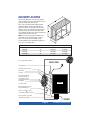
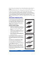
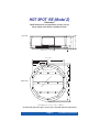
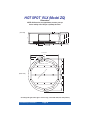
1
Congratulations on your decision to enjoy the finest spa available...
®
Welcome to the growing family of Hot Spot Spa owners.
Pre-Delivery Instructions
lease take the time to read this booklet carefully, as it will provide you with the information you will need to
ensure the safe, secure, and timely installation of your new spa. The following sections are guidelines on how to
prepare for delivery and set-up of your new spa. Specifically covered are site selection, delivery access, ground
preparation, and electrical requirements.
P
Remember to carefully read the Owner’s Manual that accompanies your spa, and to complete the warranty card
within 10 days of delivery. These items, along with other valuable information, will be found in the Owner’s Package
which has been placed in the equipment compartment of your spa, where you will also find its serial number.
Watkins Manufacturing Corporation reserves the right to change features, specifications and design without
notification and without incurring any obligation.
DATE PURCHASED: __________________________________________________________________________
DATE INSTALLED:______________________________________________________________________________
DEALER:______________________________________________________________________________________
ADDRESS: ____________________________________________________________________________________
TELEPHONE:__________________________________________________________________________________
n most cities and counties, permits will be required for the installation of electrical circuits or the construction of
exterior surfaces (decks and gazebos). In addition, some communities have adopted residential barrier codes
which may require fencing and/or self-closing gates on the property to prevent unsupervised access to a pool (or
spa) by children under 5 years of age. Your Hot Spot® Spa is equipped with a locking cover that meets the ASTM
F1346-91 Standard for Safety Covers and as a result, is usually exempt from most barrier requirements. As a
general practice, your local Building Department will inform you of any applicable barrier requirements at the time a
permit is obtained for the installation of an electrical circuit. Your Hot Spot® Spa Dealer can provide information on
which permits may be required.
I
Hot Spot® Spa Pre-Delivery Instructions
Site Selection and Preparation
IMPORTANT: Site selection and preparation are your responsibility. Carefully read these instructions and consult
your authorized Hot Spot® Spa Dealer if you have any questions.
ou probably have a spot picked out for your new spa, whether it’s indoors or outdoors, on a patio or on a
deck. Just make sure you check the following:
• Always put your spa on a structurally sound, level surface. A filled spa can weigh a great deal. Make
certain that the location you choose can support the weight of your filled spa.
• Don’t forget to level your spa before filling it. (See Spa Leveling Instructions included in Owner’s Manual.)
• Locate your equipment compartment, which houses all of the electrical components, in a place where
water will drain away from it. Allowing water into the equipment compartment can damage the
electronics, or may result in tripping your house’s circuit breaker.
• Leave yourself easy access to the circuit breakers in the subpanel (converted 30 amp), or to the
interrupter switch by the end of the power cord (115 volt models).
• Never let water get into the subpanel (converted 30 amp), into the interrupter switch (standard), or into
the electrical outlet that your spa is plugged into.
• Leave access to the equipment compartment for periodic spa care and maintenance.
Y
OUTDOOR AND PATIO INSTALLATION
o matter where you install your new spa, it’s important that you have a solid foundation to support it.
Structural damage to the spa resulting from incorrect installation or placement on an inadequate foundation
is not covered under the spa’s limited warranty.
N
If you install the spa outdoors, a reinforced concrete pad at least four inches thick is recommended for your Hot
Spot® Spa. The reinforcing rod or mesh in the pad should be attached to a bond wire (see your Owner’s Manual).
If you place the spa on the ground, even temporarily, place stepping stones under the leveling areas (see Spa
Leveling Instructions in your Owner’s Manual). The stones should be at least two inches thick and twelve inches
square. Even with stones in place, the spa will inevitably settle and become unlevel. Plus, a spa surrounded by
dirt or grass will soon be filled with dirt or grass from users’ feet; therefore, it is important to get it onto a solid
foundation as soon as possible.
DECK INSTALLATION
o be certain your deck can support your spa, you must know the deck’s maximum load capacity. Consult a
qualified building contractor or structural engineer before you place the spa on an elevated deck or
indoors. To find the weight of your spa, its contents and occupants, refer to the Spa Specification chart. This
weight per square foot must not exceed the structure’s rated capacity, or serious structural damage could result.
T
INDOOR INSTALLATION
e aware of some special requirements if you place your spa indoors. Water will accumulate around the spa,
so flooring materials must provide a good grip when wet. Proper drainage is essential to prevent a build-up
of water around the spa. When building a new room for the spa, it is recommended that a floor drain be installed.
The humidity will naturally increase with the spa installed. Water may get into woodwork and produce dryrot,
mildew, or other problems. Check for airborne moisture’s effects on exposed wood, paper, etc. in the room. To
minimize these effects, it is best to provide plenty of ventilation to the spa area. An architect can help to
determine if more ventilation must be installed.
B
Your Hot Spot® Spa Dealer can help you with local information such as zoning regulations and building codes.
Pre-Delivery Instructions
Page 2
DELIVERY ACCESS
First, locate the dimensions of your spa on the following
chart. The dimensions shown are the measurements of the
spa in the vertical position, laid on its side.
Next, contact your dealer to find the height and width
added by the delivery cart which the dealer will use to
deliver your new spa. Use the height of the cart plus the
dimension shown as H to determine the vertical clearance
required to pass the spa and cart. Use the width of the
cart, or dimension W, whichever is greater, to determine the
maximum width of clearance necessary.
NOTE: It may be necessary to allow for additional overhead clearance if the spa will be rolled up or down an
incline or moved up or down a short flight of stairs.
Use the information below to determine the requirements
for access to your desired location.
Model
Width W
Length L
Height H
RE (Z)
29"
78" Round
78" Round
RLX (ZQ)
33"
78" Round
78" Round
SLX (YQ)
33"
78" Square
78" Square
SLXtra (W)
33"
71" Square
71" Square
How is your width clearance?
BACK YARD
Check all gates
Protruding electric meters
Gas meters
A/C units
Do you have sufficient
overhead clearance?
Check low roof eaves,
overhanging branches,
rain gutters
HOUSE
Is the path clear?
Move away branches, dog
houses, firewood, etc.
If there is a 90 turn, can we
clear it? (The spa will not bend)
No more than 6 consecutive
stairs without a landing
STREET
Page 3
Pre-Delivery Instructions
It may be necessary to remove a gate, part of a fence, or other movable obstructions in order to roll the spa to its
installation site. About ten percent of the time, a crane is the only way to install the spa by lifting it to its final
destination.
If the spa has to be taken off of the cart to go over a wall (either because the entry area is too narrow, the eaves are
too low, the corner is too tight, or the stairway is too steep), a crane will be required. Don’t be alarmed!
The crane has a truck-mounted boom which can fit right in your driveway. It is run by a licensed and insured
operator. For a charge, the crane operator will lift your spa over walls, buildings, or any other obstruction and place
it as close to the installation site as possible. The Hot Spot® Spa delivery personnel will supervise the crane delivery
and complete the spa installation. Crane delivery typically takes an average of 30 minutes to complete.
NOTE: If your spa delivery requires the use of a crane, you may be required to pay for its services at the completion
of the delivery.
GROUND PREPARATION
Your Hot Spot® Spa has been engineered to perform on all kinds
of common yard surfaces. While a concrete slab is best for longterm use*, other foundations are acceptable so long as a level
base is prepared prior to delivery. Three foundation base pictures,
shown at right, represent examples of alternatives to a concrete
slab for spas installed without gazebos or other accessories.
*NOTE: A reinforced concrete pad at least four inches thick is
recommended for your Hot Spot® Spa.
FOUNDATIONS FOR SPAS ONLY
(No accessories such as cover or gazebo)
PEA GRAVEL
OR CRUSHED ROCK
INSTALLATION NOTES:
• If stepping stones or railroad ties are selected for the spa
foundation, they should be placed at the designated leveling
areas of your spa to maintain even distribution of the spa
weight.
• It is important to note that soft surfaces, even when
stepping stones are used to distribute the weight of the spa
as evenly as possible, will still have a tendency to settle
unevenly, resulting in an unlevel spa.
• Remember, placing the spa on grass or dirt may increase
the amount of debris which is inadvertently brought into the
spa water on the user’s feet.
If you are purchasing a deck package or a gazebo with your spa,
a solid foundation becomes mandatory. Placing them on any
surface other than a single level pad could create problems with
their installation. Pictured at right are a few of the recommended
surfaces.
As a homeowner, it is your responsibility to provide a suitable,
level foundation for your spa. Keep in mind that most delivery
crews are not equipped to level and prepare spa sites.
If you are interested in having a concrete slab, brick surface, or
wood deck installed, your Hot Spot® Spa Dealer should be able to
suggest a qualified, licensed contractor.
NOTE: In order for the spa to operate properly and the internal
plumbing to drain completely, you must ensure that the spa is
leveled after it has been installed. The diagrams on the following
pages indicate the recommended shimming points on your spa’s
base support system. Your Hot Spot® Spa delivery crew can help
you perform the procedure.
Pre-Delivery Instructions
Page 4
RAILROAD TIES
PRE-CAST
STEPPING STONES
FOUNDATIONS FOR SPAS
WITH ACCESSORIES
CONCRETE PADS
BRICK SURFACES
WOOD DECKING
HOT SPOT RE (Model Z)
®
Dimensions
NOTE: All dimensions are approximate; measure your spa
before making critical design or pathway decisions.
(Front view)
22.5" 25.5"
29.0"
7.5"
26.5"
1.5"
DOOR SIDE
68.5"
34.3"
31"
21"
16.0"
20.0"
EW
O
F
SP
A
ELECTRICAL CUTOUT
O
W
N
VI
(Bottom view)
UP
SI
D
E
D
78.0"
20.0"
16.0"
• 15 Leveling Points (place shims approx. 12" in from edge, center middle shims, then shim perimeter).
Page 5
Pre-Delivery Instructions
HOT SPOT RLX (Model ZQ)
®
Dimensions
NOTE: All dimensions are approximate; measure your spa
before making critical design or pathway decisions.
(Front view)
32.5"
29.0"
25.0"
8.5"
26.5"
1.5"
DOOR SIDE
68.5"
34.3"
31"
21"
16.0"
20.0"
VI
EW
O
F
SP
A
ELECTRICAL CUTOUT
O
W
N
(Bottom view)
UP
SI
D
E
D
78.0"
20.0"
16.0"
• 15 Leveling Points (place shims approx. 12" in from edge, center middle shims, then shim perimeter).
Pre-Delivery Instructions
Page 6
HOT SPOT SLX (Model Y)
®
Dimensions
NOTE: All dimensions are approximate; measure your spa
before making critical design or pathway decisions.
(Front view)
32.5"
29.0"
25.0"
8.5"
26.0"
1.5"
25.5"
DOOR SIDE
69.5"
34.8"
33.5"
24"
ELECTRICAL CUTOUT
VI
EW
O
F
SP
A
17.0"
28.5"
UP
SI
D
E
D
O
W
N
(Bottom view)
24.0"
• 12 Leveling Points (place shims approx. 12" in from edge, then center middle shims)
Page 7
Pre-Delivery Instructions
HOT SPOT SLXtra (Model W)
®
Dimensions
NOTE: All dimensions are approximate; measure your spa
before making critical design or pathway decisions.
(Front view)
33.0"
29.5"
23.5"
6.8"
11.0"
DRAIN
3.5"
35.0"
40.5"
22.0"
VI
EW
O
F
SP
A
(Bottom view)
71.0"
UP
SI
D
E
D
O
W
N
22.0"
24.0"
15.0"
19.0"
15.0"
68.0"
71.0"
DOOR SIDE
• 12 Leveling Points (place shims approx. 15" in from edge, then center middle shims)
Pre-Delivery Instructions
Page 8
ELECTRICAL REQUIREMENTS
To ensure you will have an opportunity to use your spa soon after delivery, it is very important that the required
electrical service has been installed. Unless otherwise stipulated by your dealer, THIS IS YOUR RESPONSIBILITY.
IMPORTANT: All electrical circuits must be installed by a qualified, licensed electrician.
our Hot Spot® Spa has been carefully designed to give you maximum safety against electrical shock.
Connecting the spa to an improperly wired circuit will negate many of the spa’s safety features. Please read and
follow the electrical installation requirements and instructions for your specific spa model completely!
Y
There are three electrical configurations associated with Hot Spot® Spas. Each spa comes standard as a 115 volt
15 amp or 20 amp (SLXtra), cord-connected electrical configuration, which is designated as an “either/or”
hydromassage system. This means that the heater will not activate simultaneously with the high speed mode of the
jet pump. If you use your spa for extremely long periods of time with the high speed jet pump operating, you may
experience a slight drop in water temperature. This happens because the heater will not heat while the pump is
running on high. To allow the heater to operate at the same time as the high speed jet pump, the spa may be
converted (by an authorized technician) to a 115 volt 30 amp hard-wired configuration. The 30 amp configuration
provides enough electrical current to allow the heater and the high speed jet pump to operate simultaneously.
Conversion requires electrical modification within the control box (contact an authorized Hot Spot® Service
Technician) and the installation of an electrical subpanel (available from your Hot Spot® Dealer). A licensed
electrician must install the subpanel.
ELECTRICAL REQUIREMENTS
The spa must be connected to a 115 volt, 15 or 20 amp (30 amp for converted
models) grounded circuit. The equipment pack requires a MINIMUM of 104
volts under load. A dedicated circuit is required; the term “dedicated” means
the electrical circuit is not being used for any other high-load electrical items
(patio lights, appliances, garage circuits, etc.). If the spa is connected to a nondedicated circuit, overloading will result in “nuisance tripping” of the internal
fuses or of the breaker switch at the house electrical breaker panel.
The circuit must be properly wired; that is, it must have the following:
• Standard (cord-connected) 115 volt 15 amp – A minimum 15 amp
GFCI circuit breaker in the house breaker panel, #14 AWG or larger wire
(including the ground wire) and the correct polarity throughout the circuit.
• Standard (cord-connected) 115 volt 20 amp (SLXtra Spa only) - A
minimum 20 amp GFCI circuit breaker in the house panel, #12 AWG or
larger wire (including the ground wire) and the correct polarity throughout
the circuit.
(SLXtra G.F.C.I. Illustrated)
• Converted (hard-wired) 115 volt 30 amp – A minimum 30 amp circuit
breaker in the house breaker panel, #10 AWG or larger wire (including the ground wire), a subpanel with an
appropriate GFCI breaker, and the correct polarity throughout the circuit.
A pressure wire connector is provided on the exterior surface of the spa’s electrical control box, located inside the
equipment compartment. This is to permit the connection of a bonding ground wire between this point and any
metal equipment, enclosures, pipe or conduit within five feet of the spa (if needed to comply with local building
code requirements). The bonding wire must be at least a #8 AWG solid copper wire.
NEVER CONNECT THE SPA TO AN EXTENSION CORD!
Each Hot Spot® Spa comes equipped with approximately 15 feet of usable power cord (this is the maximum length
allowed by regulatory standards and the National Electric Code). The power cord is stored for shipping inside the
equipment compartment. To remove the power cord, open the equipment compartment and locate the cord.
Carefully pull the cord out of the equipment compartment to the desired length.
If you choose to convert your spa to 115 volt 30 amp operation (contact an authorized Hot Spot® Spa Service
Technician to perform the conversion), a licensed electrician must install the subpanel (available from your
Hot Spot® Spa Dealer).
x
Page 9
x
Pre-Delivery Instructions
x
STANDARD, CORD-CONNECTED 115 VOLT 15 OR 20 AMP
CONFIGURATION
For your safety, if you are having an electrician install an electric outlet for the spa outdoors, it should be no closer
than ten (10) feet and no further than fifteen (15) feet from the spa. If the spa is being installed indoors, it should be
no closer than five (5) feet and no further than ten (10) feet from the spa. [Reference National Electrical Code
680 - 6a(1) and 680 - 41a.]
One GFCI is used in the cord-connected 15 or 20 amp configuration. The GFCI module is located at the end of the
power cord. To test the GFCI, simply press the TEST button. The GFCI should trip to the “off” position,
disconnecting power to the spa. To reset the GFCI, press the RESET button. The GFCI should reset, and power
should be restored to the spa. If the GFCI does not function in this way, unplug the cord and contact an authorized
Hot Spot® Spa Service Technician.
NOTE: Consult your local code authority to determine if an electrical outlet with a cover is required for your installation.
If it is, a suitable outlet cover may be purchased from your Authorized Hot Spot® Dealer. Ask for Part #71591.
CONVERTED 115 VOLT 30 AMP CONFIGURATION
30 Amp Subpanel Wiring Instructions
NOTE: The subpanel must be placed within 100 feet of the main electrical service panel, and between 5 and 50 feet
away from the spa. Refer to the wiring diagram below. A 115 volt 30 amp subpanel may be purchased from your
local Hot Spot® dealer, ask for Part # 37573 or # 37546.
A licensed electrician should install three-wire electrical service (one line voltage, one neutral, one ground) from the
main electrical service panel; to the subpanel.
The grounding conductor must be the same gauge as the line conductor, but at least #10 AWG. Your electrician
should mount the subpanel in the vicinity of the spa but it should not be closer than five (5) feet from the spa water
edge (NEC 680-6c).
INSTALLATION NOTE: After the spa has been installed by the dealer’s delivery crew, your electrician can connect
the conduit from the subpanel to the spa’s Control Box and then complete the wiring connections in the control box.
NOTE: Complete step-by-step Installation and Wiring Instructions for all 30 amp Hot Spot® Models are included in
the Owner’s Manual and with each subpanel obtained from your dealer.
WARNING: Removing or bypassing the GFCI circuit breakers in the subpanel at any time will result in an unsafe
spa and will void the warranty.
Wire Specification
NOTE: Long Electrical runs may require a larger gauge feed wire than stated. We recommend that a maximum
voltage drop of3% be used when calculating the larger wire size.
x
Pre-Delivery
Instructions
Page
Page10
x
x
RE
(Model Z)
6'6"
x
6'6"
29"
RLX
(Model ZQ)
6'6"
x
6'6"
33"
SLX
(Model YQ)
6'6"
x
6'6"
33"
SLXtra
(Model W)
5'11"
x
5'11"
33"
Ef
filt fectiv
er
are e
He a
(W ater
att
s)
Wa
ca ter
pa
cit
y
Dr
yw
eig
ht
Fill
ed
we
igh
t*
De
ad
we
igh
Ele
t*
Re ctric
qu al
ire
me
nts
Fo
dim otpr
en int
sio
ns
He
igh
t
Spa Specifications
30
Square
feet
1,000
30
Square
feet
1,000
30
Square
feet
1,000
30
Square
feet
1,000
230
Gallons
264
Lbs.
2,834
Lbs.
100
Lbs. per
square
foot
245
Gallons
300
Lbs.
2,992
Lbs.
100
Lbs. per
square
foot
285
Gallons
382
Lbs.
3,574
Lbs.
100
Lbs. per
square
foot
285
Gallons
442
Lbs.
3,634
Lbs.
100
Lbs. per
square
foot
115 volt, 15 amp
(standard)
115 volt, 30 amp
grounded circuit
(optional – requires
30 amp subpanel)
115 volt, 15 amp
(standard)
115 volt, 30 amp
grounded circuit
(optional – requires
30 amp subpanel)
115 volt, 15 amp
(standard)
115 volt, 30 amp
grounded circuit
(optional – requires
30 amp subpanel)
115 volt, 20 amp
(standard)
115 volt, 30 amp
grounded circuit
(optional – requires
30 amp subpanel)
CAUTION: Watkins Manufacturing suggests a structural engineer or contractor be consulted before the
spa is placed on an elevated deck.
* NOTE: The “Filled weight” and “Dead weight” of the spa includes the weight of the occupants
(assuming an average occupant weight of 175 lbs).
CONTRACTOR SUGGESTIONS
Electrician
Name:
______________________________________________________________________________________
Telephone:
______________________________________________________________________________________
Name:
______________________________________________________________________________________
Telephone:
______________________________________________________________________________________
General
Name:
______________________________________________________________________________________
Telephone:
______________________________________________________________________________________
Name:
______________________________________________________________________________________
Telephone:
______________________________________________________________________________________
x
Page
Page11
x
Pre-Delivery Instructions
x
ADDITIONAL PRODUCTS AVAILABLE FROM YOUR
HOT SPOT® SPA DEALER
• EverFresh®* water care system
• FreshWater®* III high output ozone purification
system
• Hot Spring® MPS chlorine-free oxidizer
• FreshWater™ Stain and Scale Defense
• FreshWater™ Spa Shine
• FreshWater™ Instant Filter Cleaner
• FreshWater™ Filter Cleaner
• FreshWater™ Ph-Alkalinity Down
• FreshWater™ Ph-Alkalinity Up
• FreshWater™ Defoamer
• Hot Spring® Cover Shield™
• Retractable cover system with clearance
requirements
• Cover Cradle® * – 24” Clearance required
• UpRite™* – 7” Clearance required
• GlideRite® ** – 14” Clearance required
• Vinyl covers
• Spa vacuums
• Stain kits
• Spa upgrade jet kits
• MPS test strips
• Replacement filter cartridges
• Pillows
• Others
SERVICES AVAILABLE FROM YOUR
HOT SPOT® SPA DEALER
Service
Cost
Pre-Delivery site inspection
Deliver spa to installation site
Unwrap spa and haul away packaging material
Set up & level spa
Fill the spa with water
Connect the spa to its power source (115 volt 15 or 20 amp models)
Explain and test the spa’s operation
• Jet system
• Comfort Control® system
• Set temperature control
• Control panel functions
Explain the safety features
• GFCI
• Heater high limit
• Heater thermal cut-off
General spa operation & maintenance orientation
Water quality and maintenance orientation
Adjust the water’s Total Alkalinity, Calcium Hardness and pH
Sanitize the water
Inspect the spa cover, place on spa
Review winterizing instructions
Review Owner’s Manual & Warranty Card
Follow-up call
In-store spa water analysis
TOTAL COST
* Used on SLXtra model only
** Used on SLX and SLXtra models only
x
Pre-Delivery
Instructions
______________
______________
______________
______________
______________
______________
______________
______________
______________
______________
______________
______________
______________
______________
______________
______________
Page
Page12
x
x
NOTES:
Page 13
Pre-Delivery Instructions
®
WATKINS MANUFACTURING CORPORATION
1280 Park Center Drive
Vista, California 92083
(800) 999-4688 extension 432
©2001 Watkins Manufacturing Corporation. Hot Spot, Comfort Control, Cover Cradle, UpRite, GlideRite, Cover Shield,
EverFresh, FreshWater and The Home Relaxation Specialists are trademarks of Watkins Manufacturing Corporation.
Part #61604 Rev. A (3/01)