1
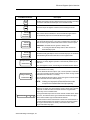
SED2 VFD Electronic Bypass Option
Operating Instructions
Item Number 125-3208, Rev. 011
SED2 VFD Electronic
Bypass Option
Operating Instructions
NOTICE
The information contained within this document is subject to change without notice and should not be
construed as a commitment by Siemens Building Technologies, Inc. Siemens Building Technologies, Inc.
assumes no responsibility for any errors that may appear in this document.
All software described in this document is furnished under a license and may be used or copied only in
accordance with the terms of such license.
WARNING
The Siemens Building Technologies SED2 Variable Frequency Drives are shipped without EMC line filters.
(The EMC filter is most commonly used in Europe.) Where local codes or customer/installation requirements
dictate, separately orderable line filters are available. More stringent Class B line filters are also available for
most models. Installation of these filters satisfies the requirements for the EU's EMC directive.
SERVICE STATEMENT
Control devices are combined to make a system. Each control device is mechanical in nature and all
mechanical components must be regularly serviced to optimize their operation. All Siemens Building
Technologies, Inc. branch offices and authorized distributors offer Technical Support Programs that will
ensure your continuous, trouble-free system performance.
For further information, contact your nearest Siemens Building Technologies, Inc. representative.
CREDITS
Product or company names mentioned herein may be the trademarks of their respective owners.
Copyright © 2003 by Siemens Building Technologies, Inc.
TO THE READER
Your feedback is important to us. If you have comments about this manual, please submit them to
[email protected].
Printed in U.S.A.
Table of Contents
Table of Contents
How to Use this Manual................................................................................................1
Manual Organization..................................................................................................1
Manual Notations .......................................................................................................1
Where To Send Comments .......................................................................................1
Reference Documents ...............................................................................................2
Safety Instructions........................................................................................................3
Electronic Bypass Option Overview ...........................................................................4
General Description ...................................................................................................4
Controller Board.........................................................................................................5
Contactors..................................................................................................................6
Keypad Functions ......................................................................................................6
Installation Instructions ...............................................................................................8
Environmental Conditions..........................................................................................8
Mechanical Installation ..............................................................................................8
Inspection ................................................................................................................8
Dimensions and Weights ........................................................................................8
Mounting..................................................................................................................9
Electrical Installation ..................................................................................................10
Startup Procedures.......................................................................................................16
Safety Precautions.....................................................................................................16
Installation Inspection ................................................................................................16
Power-On...................................................................................................................16
Required SED2 VFD Parameter Settings ....................................................................18
Application Feature Setup ...........................................................................................19
Overview ....................................................................................................................19
Auto Bypass without Interlock....................................................................................19
Description ..............................................................................................................19
Settings ...................................................................................................................20
Example VFD Settings ............................................................................................20
Interlock .....................................................................................................................21
Description ..............................................................................................................21
Settings ...................................................................................................................22
Siemens Building Technologies
i
SED2 VFD Electronic Bypass Option Operating Instructions
Wiring Example for Interlock ...................................................................................22
Essential Services......................................................................................................23
Description ..............................................................................................................23
Settings ...................................................................................................................23
Wiring Example for Essential Services ...................................................................23
Interlock and Auto Bypass on VFD Fault...................................................................24
Description ..............................................................................................................24
Settings ...................................................................................................................24
Wiring Example for Interlock and Auto Bypass on VFD Fault ................................24
Technical Specifications ..............................................................................................25
Troubleshooting............................................................................................................26
Power-on Initialization Failure (Unit Fault Condition) ...............................................26
Override Jumper ........................................................................................................27
Fuses .........................................................................................................................27
ii
Siemens Building Technologies
How to Use this Manual
How to Use this Manual
Manual Organization
This manual contains the following sections:
•
How to Use this Manual, describes the organization of this manual and the symbols used
throughout this manual.
•
Safety Instructions, provides general guidelines for your safety and to prevent equipment
damage.
•
SED2 VFD Electronic Bypass Option Overview, describes the Electronic Bypass Option
Controller board, inputs, outputs, contactors, and keypad.
•
Installation Instructions, provides mounting information and details on electrical connections.
•
Startup Procedures, provides step-by-step procedures to start up the Electronic Bypass
Option.
•
Application Feature Setup, describes application features and provides the necessary
parameter settings.
•
Technical Specifications, lists Electronic Bypass Option specification data.
•
Troubleshooting, provides guidelines for troubleshooting the Electronic Bypass Option.
Manual Notations
Notation
Symbol
Meaning
WARNING:
Indicates that equipment damage, or loss of data may occur if you do not
perform a procedure as specified.
CAUTION:
Indicates that equipment damage, or loss of data may occur if you do not
perform a procedure as specified.
NOTES:
(no symbol)
Provides other important information or helpful hints.
Where To Send Comments
Your feedback is important to us. If you have comments about this manual, please submit them to
[email protected].
Siemens Building Technologies
1
SED2 VFD Electronic Bypass Option Operating Instructions
Reference Documents
The following SED2 VFD documentation is available from your local Siemens Building
Technologies representative:
•
SED2 VFD Operation & Maintenance Manual (125-3202), operating instructions and
procedures for the SED2 VFD.
•
SED2 VFD Startup Guide (125-3201), a brief guide to operation offers fast access to all basic
information necessary to set up, commission, and operate a SED2 VFD or SED2 VFD with
Bypass Option.
•
SED2 VFD Submittal Sheet (154-042), a synopsis of the SED2 VFD product line, accessories
and technical data.
2
Siemens Building Technologies
Safety Instructions
Safety Instructions
The following general guidelines are provided for your safety, to prevent damage, and to extend
the service life of the SED2 product and any connected equipment. Read this information
carefully. Specific Warnings, Cautions, and Notes are provided in the relevant sections of this
manual.
WARNINGS:
NOTE:
•
The SED2 uses hazardous voltages and controls potentially dangerous rotating
mechanical parts. Non-compliance with warnings or failure to follow the
instructions contained in this manual can result in loss of life, severe personal
injury, or serious damage to property/equipment.
•
Only authorized personnel should work on this equipment, and only after
becoming familiar with all local regulations and ordinances; safety notices; and
installation, operation, and maintenance procedures in this manual. Successful
and safe operation of this equipment depends upon its proper handling,
installation, operation, and maintenance.
•
Before carrying out any installation and commissioning procedures, you must
read all safety instructions and warnings, including all warning labels attached to
the equipment. Make sure that the warning labels are kept in a legible condition
and ensure missing or damaged labels are replaced.
•
Observe the regulations of Safety Code VBG 4.0 (in particular, “Permissible
Deviations when Working with Live Parts”) whenever measuring or testing is
performed on live equipment. Also, use suitable electronic tools.
•
Only use this equipment for the purpose specified by the manufacturer.
Unauthorized modifications and the use of spare parts and accessories that are
not sold or recommended by the manufacturer of the equipment can cause
fires, electric shocks, and injuries.
•
Prevent the general public from accessing or approaching this equipment.
Keep these Operating Instructions near the equipment and available to all users.
Siemens Building Technologies
3
SED2 VFD Electronic Bypass Option Operating Instructions
Electronic Bypass Option Overview
General Description
During normal operation in a typical
application, the input and output
contactors close and the VFD operates
the motor (Figure 1). The bypass
contactor provides the ability to operate
the motor on utility power and eliminate
the VFD from the motor control circuit.
The SED2 VFD Electronic Bypass
Option also allows the user to select
features that enhance the control of the
contactors and the outputs that report
operation.
BYPASS
CONTACTOR
VFD0093R1
VFD
•
Keypad
•
Step-down power transformer
•
Contactors:
−
Bypass
−
Output
−
Input (optional)
•
Overload (current) relay
•
Reactor (optional)
•
Disconnect switch (or optional
circuit breaker)
•
Fuses (optional)
•
Cable harnesses
CONTROLLER
BOARD
MOTOR
OUTPUT
CONTACTOR
SED2 VFD
KEYPAD
(DOOR
MOUNTED)
INPUT
CONTACTOR
STEP-DOWN
POWER
TRANSFORMER
REACTOR
(OPTIONAL)
OUTPUT
CONTACTOR
BYPASS
CONTACTOR
VFD0094R1
Controller board
INPUT
CONTACTOR
Figure 1. Functional Block Diagram of
Typical Electronic Bypass Option.
The SED2 VFD Electronic Bypass
Option consists of a SED2 VFD, and a
bypass enclosure with electronic
controls (Figure 2). The electronic
controls include:
•
OVERLOAD
RELAY
OVERLOAD
(CURRENT)
RELAY
DISCONNECT
SWITCH
(OR OPTIONAL
CIRCUIT BREAKER
SHOWN)
Figure 2. Typical SED2 VFD Electronic Bypass Option
Components.
4
Siemens Building Technologies
Electronic Bypass Option Overview
Controller Board
The Controller board is the foundation of the SED2 VFD Electronic Bypass Option. It controls
communications to and from the SED2 VFD, keypad, isolated digital inputs, relay/digital outputs,
and contactors (Figure 3).
SED2 VFD INTERFACE
Supports two SED2 VFD non-isolated, digital relay
outputs and three SED2 VFD digital inputs. The
maximum current draw for a relay output is 2 mA and
the voltage between the digital output source and return
lines is 24V. The Controller board provides unregulated,
non-isolated 24V to power the SED2 VFD digital inputs.
J4
CONTROLLER
BOARD
BASIC SANITY TEST INDICATOR
Provides indication of initialization and
normal operation.
FACTORY USE ONLY
Connector J8 is for factory use only.
DIGITAL INPUTS
Supports six isolated digital inputs for customer use.
The inputs require a contact closure capable of
providing a low impedance path at currents less
than 20 mA.
J3
MCU
ON
OFF
J8
SW1
KEYPAD INTERFACE
Supports inputs and outputs from the Electronic
Bypass Option keypad. The keypad provides
user interface indicators and push buttons.
J2
J1
TRANSFORMER
DIGITAL RELAY OUTPUTS
Supports six digital relay outputs for customer use.
Each relay has a maximum rating of 2A at 120 Vac.
J6
OVERRIDE JUMPER
5
ON
5
J5
CONTACTOR POWER
CONTROLS
2
Automatic Bypass selector switch;
requires SED2 VFD programming.
Essential Services selector switch.
SW1
ON
Not used, factory test selector switch #2;
leave this switch OFF.
Not used, factory test selector switch #1;
leave this switch OFF.
Interlock selector switch; requires
SED2 VFD programming.
1
3
4
OPTIONS
3
4
2
1
J7
OFF
DIP SWITCHES
The Controller board DIP switches enable/disable
the Electronic Bypass Option features.
VFD0095R1
F1
When the switch is ON the option is enabled;
when the switch is OFF the option is disabled.
Figure 3. Controller Board Inputs and Outputs.
Siemens Building Technologies, Inc.
5
SED2 VFD Electronic Bypass Option Operating Instructions
Contactors
The Controller board provides two or three relay contact circuits for controlling the Electronic
Bypass Option: bypass, input, and output contactors. Each circuit includes a NO relay. Controller
board connector J7 enables circuit connections. The relay circuits route power to the SED2 VFD
and the motor via the contactors. Controlling the contactors through the relay circuits is the main
function of the Controller board.
Bypass Contactor – The bypass relay on the Controller board controls the bypass contactor.
The output and bypass relays are interconnected to 120 Vac Hot. This enables a safety circuit
that prevents the bypass and output contactors from simultaneously being energized.
Output Contactor – The output relay on the Controller board controls the output contactor.
Input Contactor – The input relay on the Controller board controls the optional input contactor.
Keypad Functions
Input
Contactor
VFD
Enable
Bypass
VFD
Hand
Start
Input
On/Off
Bypass
Contactor
Overload
Relay
Bypass
Input
Contactor
VFD
Remote
Start
Enable
Motor
VFD Fault
STOP
RESET
Safety Fault
Essential Services
INTERLOCK START LOGIC
Overload Fault
Enable Commanded Proofed
2-CONTACTOR KEYPAD
VFD0097R1
VFD0096R1
Auto Bypass Enabled
Remote
Start
Output
Contactor
Motor
STOP
RESET
Bypass
Contactor
Overload
Relay
Output
Contactor
Hand
Start
Auto Bypass Enabled
VFD Fault
Safety Fault
Essential Services
INTERLOCK START LOGIC
Overload Fault
Enable Commanded Proofed
3-CONTACTOR KEYPAD
Figure 4. Electronic Bypass Option Keypad Indicators and Push Buttons.
The keypad provides user interface indicators and push buttons. The following table describes
specific push button and indicator functions:
VFD0100R1
VFD0099R1
VFD0098R1
Push Button/Indicator
6
Description
Input
On/Off
The Input On/Off push button is supplied with the optional drive input
contactor. In VFD mode, this switch does nothing. In bypass mode, this
switch closes/opens the input contactor, switching the SED2 VFD power
on/off.
Enable
Enables SED2 VFD operation by closing the input and output contactors.
Hand
Start
Manually enables bypass mode operation by ensuring that the output
contactor is open and then closing the bypass contactor.
Siemens Building Technologies
Electronic Bypass Option Overview
VFD0102R1
VFD0101R1
Push Button/Indicator
Remote
Start
Activates the bypass mode and operates the bypass contactor according
to the status of the Remote Start input on the Controller board.
STOP
RESET
Opens the output and bypass contactors, disconnecting the motor.
VFD0103R1
VFD Fault
Safety Fault
VFD0104R1
Safety Fault
Overload Fault
VFD Fault
VFD0105R1
When a VFD Fault is indicated, the VFD Fault indicator lights and the
VFD Fault Relay output on the Controller Board is triggered.
Overload Fault
VFD Fault
Safety Fault
The Safety Fault indicator lights when either of the Remote Safety inputs
on the Controller board opens. The motor is prohibited from operating in
either the VFD or bypass modes while either of these contacts is open.
EXCEPTION: Essential Services ignores a Safety Fault.
NOTE:
If not using the Remote Safety feature, hard wire the two
Remote Safety inputs.
If the Electronic Bypass Option current overload relay trips, the Overload
Fault indicator lights and the motor will not run in bypass mode.
Overload Fault
Auto Bypass Enabled
VFD0106R1
Description
Essential Services
When the Auto Bypass DIP switch is enabled, the Auto Bypass Enabled
indicator is on steady. Bypass operation is automatically initiated by the
SED2 VFD.
When Auto Bypass is active, the Auto Bypass Enabled indicator flashes.
When the Essential Services DIP switch is enabled, the Essential
Services indicator is on steady.
VFD0107R1
Auto Bypass Enabled
Essential Services
When the Essential Services input is open, normal operation is indicated
as the output contactor remains closed to keep the motor running and the
Essential Services indicator is on steady.
When the Essential Services input is closed, the bypass contactor closes
and the Essential Services indicator flashes.
NOTE:
Nothing can interrupt the Essential Services mode
except for the Essential Services input opening.
VFD0108R1
When the Interlock DIP switch is enabled, the Interlock Start Logic Enable
indicator is on steady. Any call to start the motor in either VFD or bypass
modes will not start the motor but instead closes the Programmable
Output relay on the Controller board.
INTERLOCK START LOGIC
Enable Commanded Proofed
The Programmable Output can be used to actuate another device. When
this occurs, the Interlock Start Logic Commanded indicator also lights,
and the Interlock Start Logic Proofed indicator flashes.
A contact closure from this other device is wired to the Interlock Start on
the Controller Board which then starts the motor and turns the Interlock
Start Logic Proofed indicator on steady. This feature is also called
damper end switch relay logic.
Siemens Building Technologies, Inc.
7
SED2 VFD Electronic Bypass Option Operating Instructions
Installation Instructions
Environmental Conditions
Install the Electronic Bypass Option in a heated, indoor controlled environment that is free of
moisture and conductive contaminants such as condensation and dust. The air entering the unit
for ventilation/cooling must be clean and free from corrosive materials.
The ambient temperature must be between 32°F and 104°F (0°C to 40°C) and the relative
humidity must be 0% to 95% noncondensing. Do not mount unit in direct sunlight.
Mechanical Installation
Inspection
1. As you unpack the Electronic Bypass Option, check for shipping damage. In the event of
damage, contact the transport company.
2. Locate the Electronic Bypass Option nameplate and confirm that the unit is configured to the
installation requirements.
3. Verify the delivery is complete. If not, contact the supplier.
Dimensions and Weights
Figure 5 shows overall and mounting dimensions for the Electronic Bypass Option.
Approximate weights are as follows.
NOTE:
Actual weights vary depending on the power option selected.
Frame Size
8
Weight in lb (kg)
A
55 (25)
B
65 (29)
C
100 (45)
D
170 (77)
E
200 (91)
F
500 (227)
Siemens Building Technologies
Installation Instructions
Mounting
1. To ensure safe installation, verify that the surface of the mounting location is level.
2. Mount the Electronic Bypass Option vertically with the SED2 VFD operator panel, Electronic
Bypass Option keypad, and disconnect accessible.
Depth
With
Handle
10.4 (26)
= Protective Shield
Depth
With
Handle
9.6 (24)
Depth
With
Handle
9.6 (24)
13.2
(34)
11.5
(29)
20.8
(53)
1
(2.5) 2
(5)
2.9
(7.4) 4
(10)
1.5
(3.8)
57.5
(146)
48
(122)
34
(86)
10.5 TYP
(27)
12.4
(31)
10.6
(27)
1.5
(3.8)
Frame Size
A and B
Depth
With
Handle
12.2 (31)
20.8
(53)
11.5 TYP
(29)
11 TYP
(28)
19.9
(51)
2
(5)
Frame
Size C
2.9
(7.4) 3
(7.6)
3.4
(8.6)
Frame
Size D
45.5
(116)
Depth
17.4
(44)
57.5
(146)
58.5
(149)
VFD0127R1
10 TYP
(25)
NOTE:
19.9
(51)
Frame Size E
5.5
(14)
Frame Size F
It is recommended to leave 6 inches (15 cm) around the top and sides of the unit.
Figure 5. Electronic Bypass Option Dimensions in Inches (Centimeters).
Siemens Building Technologies, Inc.
9
SED2 VFD Electronic Bypass Option Operating Instructions
Electrical Installation
See Figure 6 for all Electronic Bypass Option wiring.
1. Route shielded twisted pair (recommended wire type) cable, 24 gauge minimum control
wiring in conduit through knockout and into housing (Figures 7 through 9). Connect control
wiring per job-specific drawings.
NOTES:
•
Terminate shield at control device.
•
Control wiring is 12 to 26 AWG and tightening torque is 5 lb-in.
2. If applicable, route communications wiring (P1) in conduit through knockout and into housing
(Figures 7 through 9). Continue to route communications wiring to VFD and terminate per
SED2 VFD Operation & Maintenance Manual.
3. Route motor wiring in conduit through knockout and into housing (Figures 7 through 9).
Connect motor wiring to motor overload and ground lug. See Tables 1 through 4 for wire
sizes and tightening torques.
4. Route input power wiring in conduit through knockout and into housing (Figures 7 through 9).
Connect input power wiring to disconnect switch and ground lug or to circuit breaker and
ground lug. See Tables 1 through 4 for wire sizes and tightening torques.
OPTIONAL SUPPLEMENTARY
POWER FUSES - MAIN SHORT
CIRCUIT PROTECTION BY OTHERS
(SEE NOTE 1)
DISC1
FU1
L1
1L1
(T1) (L1)
POWER
SUPPLY L2
3 PHASE (T2)
60 Hz
L3
(T3)
GND
M1
2L1
1L2
(L2)
2L2
1L3
(L3)
2L3
OPTIONAL
OPTIONAL
DRIVE INPUT INPUT LINE
CONTACTOR REACTOR
M3
3L1
R
(2) (1)
A1
A2
3L2
S
(4) (3)
B1
B2
GND
GND
LUG
3L3
(6) (5)
T
C1
OPTIONAL
OUTPUT LOAD
REACTOR
VFD
L1
U
L2
V
L3
W
C2
U1
U
A1
A2
B1
B2
C1
C2
V1
(5)
(6)
(3)
(4)
(1)
(2)
M2
1T1
(T1)
(3) (4)
1T2
(T2)
(5) (6)
1T3
(T3)
V
W
W1
OL1
(1) (2)
M
AC MOTOR
(CUSTOMER
SUPPLIED)
GND
1L1
1L2
VFD0110R1
TO
STEP-DOWN
CONTROL
TRANSFORMER
GND
LUG
NOTES:
1. BRANCH CIRCUIT PROTECTION TO BE PROVIDED BY INSTALLER,
PER UL508A, IF NOT PROVIDED WITH DRIVE.
2. FOR BYPASS OPERATION MODIFY THESE DRIVE PARAMETERS:
P0704(0) & P0704(1) = 3, P0748 = DIGITAL OUT 1 REVERSE (
).
3. CONTROL & COMMUNICATION WIRING SHOULD BE 300V UL MINIMUM.
4. COMMUNICATION WIRING SHOULD BE RUN WITH MAXIMUM SEPARATION
POSSIBLE FROM ALL OTHER WIRING.
5. ESSENTIAL SERVICE MODE OPERATES THE MOTOR FULL SPEED (BYPASS)
WITH NO PROTECTION FOR THE MOTOR OR SYSTEM.
6. ENSURE THAT AUTOMATIC BYPASS WILL NOT DAMAGE THE SYSTEM
BEFORE ACTIVATING.
7. REFER TO SIEMENS PUBLICATION NO. 125-3208 FOR PROPER FUSE
AND WIRE SIZES.
8. REFER TO SIEMENS PUBLICATION NO. 125-3208 FOR SED2 VFD
INPUT/OUTPUT CONTROL SIGNAL WIRING DETAILS.
Figure 6. Electronic Bypass Option Wiring Schematic.
10
Siemens Building Technologies
Installation Instructions
SED2 VFD
SED2 VFD
CONTROLLER
BOARD
INPUT
CONTACTOR
(OPTIONAL)
INPUT
CONTACTOR
(OPTIONAL)
J2
CONTROL WIRING
(DIGITAL INPUTS/
OUTPUTS) VIA
2 KNOCKOUTS
COMMUNICATIONS
WIRING (P1) VIA
1 KNOCKOUT
CONTROLLER
BOARD
COMMUNICATIONS
WIRING (P1) VIA
1 KNOCKOUT
J2
CONTROL WIRING
(DIGITAL INPUTS/
OUTPUTS) VIA
2 KNOCKOUTS
J1
REACTOR
(OPTIONAL)
REACTOR
(OPTIONAL)
J1
TRANSFORMER
TRANSFORMER
POWER FUSES
(OPTIONAL)
OUTPUT
CONTACTOR
GROUND LUGS
BYPASS
CONTACTOR
GROUND LUGS
BYPASS
CONTACTOR
DISCONNECT
SWITCH
(OR OPTIONAL
CIRCUIT BREAKER)
T1T2T3
DISCONNECT
SWITCH
(OR OPTIONAL
CIRCUIT BREAKER)
L1 L2 L3
MOTOR
OVERLOAD
T1T2T3
MOTOR
OVERLOAD
MOTOR
WIRING
VIA
KNOCKOUT
INPUT
POWER
WIRING VIA
KNOCKOUT
VFD0112R1
VFD0111R1
POWER FUSES
(OPTIONAL)
OUTPUT
CONTACTOR
Figure 7. Routing of Power and Control Wiring
for Frame Sizes A and B.
MOTOR
WIRING VIA
KNOCKOUT
DISCONNECT SWITCH
(OR OPTIONAL
CIRCUIT BREAKER)
L1 L2 L3
MOTOR
WIRING
VIA
KNOCKOUT
INPUT
POWER
WIRING VIA
KNOCKOUT
Figure 8. Routing of Power and Control Wiring
for Frame Sizes C, D, and E.
GROUND
LUGS (2)
INPUT POWER
WIRING VIA
KNOCKOUT
T3T2T1
SED2
VFD
L3 L2 L1
MOTOR
OVERLOAD
BYPASS
CONTACTOR
OUTPUT
CONTACTOR
J2
J1
CONTROLLER
BOARD
VFD0113R1
TRANSFORMER
INPUT
CONTACTOR
(OPTIONAL)
POWER FUSES
(OPTIONAL)
COMMUNICATIONS
WIRING (P1) VIA
1 KNOCKOUT
REACTOR
(OPTIONAL)
Figure 9. Routing of Power and Control Wiring for Frame Size F.
Siemens Building Technologies, Inc.
11
SED2 VFD Electronic Bypass Option Operating Instructions
Table 1. Wire Sizes and Tightening Torques for Electronic Bypass Option with 208V Drive.
Circuit Breaker
Part Number
Frame
Size
VBE10.5----
A
0.5 0.37
VBE10.7----
A
0.7 0.55
VBE11.0----
A
VBE11.5----
B
VBE12.0---VBE13.0----
Hp
kW
Amps
Disconnect
Switch
Overload
Max
Backup Wire Torque,
Fuse, Size * lb-in
Amps
Wire
Size *
Torque,
lb-in
Wire
Size *
Torque,
lb-in
Wire
Size *
Torque,
lb-in
2.3
14-10
32
18-10
13-17
18-14
7-10.3 1.8-2.5
10
14-2
35
3.0
14-10
32
18-10
13-17
18-14
7-10.3 2.2-3.2
12
14-2
35
1.0 0.75
3.9
14-10
32
18-10
13-17
18-14
7-10.3
16
14-2
35
1.5
1.1
5.5
14-10
32
18-10
13-17
18-14
7-10.3 4.5-6.3
25
14-2
35
B
2.0
1.5
7.4
14-10
32
18-10
13-17
18-14
7-10.3 5.5-8.0
30
14-2
35
B
3.0
2.2
10.4
14-10
32
18-10
13-17
18-14
7-10.3
7-10
40
14-2
35
VBE15.0----
C
5.0
4.0
16.7
14-10
32
14-8
17-22
14-10
18-22
14-20
80
14-2
35
VBE17.5----
C
7.5
5.5
22.0
14-10
20-60
14-8
17-22
14-10
18-22
20-25
100
14-2
35
VBE110.----
C
10
7.5
28
10-1/0
20-60
14-8
17-22
18-3
27-40
22-32
125
14-2
35
VBE115.----
D
15 11.0
42
10-1/0
20-60
14-6
22-27
18-3
27-40
40-50
200
14-2
35
VBE120.----
D
20 15.0
54
10-1/0
20-60
12-1
22-27
10-1/0
36-53
45-63
250
14-2
35
VBE125.----
D
25 18.5
68
3-3/0-3
80
12-1
22-27
10-1/0
36-53
57-75
300
14-2
35
VBE130.----
E
30 22.0
80
3-3/0-3
80
12-1
22-27
10-1/0
36-53
70-90
350
14-2
35
40 30.0
104
6-350
kcmil
120275
12-1
22-27
6-3/0
124210
50-200
800
142/0
50
50 37.0
130
6-350
kcmil
120275
6-350
kcmil
120275
6-3/0
124210
50-200
800
142/0
50
VBE140.---VBE150.----
E
F
2.8-4
6-350
120- 6-350 120124146-3/0
50-200
800
kcmil
275
kcmil
275
210
2/0
* Wire Size in AWG unless noted otherwise. Use Copper (Cu) wire that is rated 167°F (75°C) minimum, 600 Vac.
VBE160.----
12
F
Range,
Amps
Ground Lug
60 45.0
154
50
Siemens Building Technologies
Installation Instructions
Table 2. Wire Sizes and Tightening Torques for Electronic Bypass Option with 230-240V Drive.
Circuit Breaker
Part Number
Frame
Size
VBE20.5----
A
0.5 0.37
VBE20.7----
A
VBE21.0----
A
VBE21.5---VBE22.0----
Hp
kW
Amps
Disconnect
Switch
Overload
Max
Backup Wire Torque,
Fuse, Size * lb-in
Amps
Wire
Size *
Torque,
lb-in
Wire
Size *
Torque,
lb-in
Wire
Size *
Torque,
lb-in
2.2
14-10
32
18-10
13-17
18-14
7-10.3 1.8-2.5
10
14-2
35
0.7 0.55
3.0
14-10
32
18-10
13-17
18-14
7-10.3 2.2-3.2
12
14-2
35
1.0 0.75
3.9
14-10
32
18-10
13-17
18-14
7-10.3
16
14-2
35
B
1.5
1.1
5.5
14-10
32
18-10
13-17
18-14
7-10.3 4.5-6.3
25
14-2
35
B
2.0
1.5
6.8
14-10
32
18-10
13-17
18-14
7-10.3 5.5-8.0
30
14-2
35
VBE23.0----
B
3.0
2.2
9.6
14-10
32
18-10
13-17
18-14
7-10.3
7-10
40
14-2
35
VBE25.0----
C
5.0
4.0
15.2
14-10
32
14-8
17-22
14-10
18-22
14-20
80
14-2
35
VBE27.5----
C
7.5
5.5
22
14-10
20-60
14-8
17-22
14-10
18-22
20-25
100
14-2
35
VBE210.----
C
10
7.5
28
10-1/0
20-60
14-8
17-22
18-3
27-40
22-32
125
14-2
35
VBE215.----
D
15
11.0
42
10-1/0
20-60
14-6
22-27
18-3
27-40
40-50
200
14-2
35
VBE220.----
D
20
15.0
54
10-1/0
20-60
12-1
22-27
10-1/0
36-53
45-63
250
14-2
35
VBE225.----
D
25
18.5
68
3-3/0-3
80
12-1
22-27
10-1/0
36-53
57-75
300
14-2
35
VBE230.----
E
30
22.0
80
3-3/0-3
80
12-1
22-27
10-1/0
36-53
70-90
350
14-2
35
120275
12-1
22-27
6-3/0
124210
50-200
800
142/0
50
120275
6-350
kcmil
120275
6-3/0
124210
50-200
800
142/0
50
VBE240.---VBE250.----
E
F
30.0
104
50
37.0
130
6-350
kcmil
2.8-4
6-350
120- 6-350 120124146-3/0
50-200
800
kcmil
275
kcmil
275
210
2/0
* Wire Size in AWG unless noted otherwise. Use Copper (Cu) wire that is rated 167°F (75°C) minimum, 600 Vac.
VBE260.----
F
40
6-350
kcmil
Range,
Amps
Ground Lug
60
45.0
154
Siemens Building Technologies, Inc.
50
13
SED2 VFD Electronic Bypass Option Operating Instructions
Table 3. Wire Sizes and Tightening Torques for Electronic Bypass Option with 380-480V Drive.
Circuit Breaker
Part Number
Frame
Size
VBE30.5----
A
0.5 0.37
VBE30.7----
A
VBE31.0----
A
VBE31.5---VBE32.0----
Hp
kW
Amps
Disconnect
Switch
Overload
Ground Lug
Max
Backup Wire
Fuse, Size *
Amps
Wire
Size *
Torque,
lb-in
Wire
Size *
Torque,
lb-in
Wire
Size *
Torque,
lb-in
Range,
Amps
1.1
14-10
32
18-10
13-17
18-14
7-10.3
.7-1.0
4
14-2
35
0.7 0.55
1.6
14-10
32
18-10
13-17
18-14
7-10.3 1.1-1.6
6
14-2
35
1.0 0.75
2.1
14-10
32
18-10
13-17
18-14
7-10.3 1.4-2.0
8
14-2
35
A
1.5
1.1
3.0
14-10
32
18-10
13-17
18-14
7-10.3 2.2-3.2
12
14-2
35
A
2.0
1.5
3.4
14-10
32
18-10
13-17
18-14
7-10.3
2.8-4
16
14-2
35
VBE33.0----
B
3.0
2.2
4.8
14-10
32
18-10
13-17
18-14
7-10.3
3.5-5
20
14-2
35
VBE35.0----
B
5.0
4.0
7.6
14-10
32
18-10
13-17
18-14
7-10.3
7-10
40
14-2
35
VBE37.5----
C
7.5
5.5
11
14-10
32
18-10
13-17
18-14
7-10.3
9-12
45
14-2
35
VBE310.----
C
10
7.5
14
14-10
32
18-10
13-17
14-10
18-22
11-16
60
14-2
35
VBE315.----
C
15
11.0
21
14-10
20-60
14-8
17-22
14-10
18-22
17-22
80
14-2
35
VBE320.----
C
20
15.0
27
10-1/0
20-60
14-8
17-22
18-3
27-40
22-32
125
14-2
35
VBE325.----
D
25
18.5
34
10-1/0
20-60
14-6
22-27
18-3
27-40
28-40
150
14-2
35
VBE330.----
D
30
22.0
40
10-1/0
20-60
14-6
22-27
18-3
27-40
28-40
150
14-2
35
VBE340.----
D
40
30.0
52
10-1/0
20-60
14-6
22-27
18-3
27-40
40-50
200
14-2
35
VBE350.----
E
50
37.0
65
10-1/0
20-60
12-1
22-27
10-1/0
36-53
57-75
300
14-2
35
VBE360.----
E
60
45.0
77
3-3/0
80
12-1
22-27
10-1/0
36-53
70-90
350
14-2
35
75
55.0
96
3-3/0
80
12-1
22-27
10-1/0
36-53
400
142/0
50
100 75.0
124
6-350
kcmil
120275
6-350
kcmil
120275
6-3/0
124210
800
1482/0
50
VBE375.---VBE3100----
F
F
50-200
6-350
120- 6-350 120124- 50-200
146-3/0
800
kcmil
275
kcmil
275
210
2/0
* Wire Size in AWG unless noted otherwise. Use Copper (Cu) wire that is rated 167°F (75°C) minimum, 600 Vac.
VBE3125----
14
F
80-100
125 90.0
156
Torque,
lb-in
50
Siemens Building Technologies
Installation Instructions
Table 4. Wire Sizes and Tightening Torques for Electronic Bypass Option with 500-600V Drive.
Circuit Breaker
Part Number
Frame
Size
VBE40.5----
C
0.5 0.37
VBE40.7----
C
VBE41.0----
C
VBE41.5---VBE42.0----
Hp
kW
Amps
Disconnect
Switch
Overload
Ground Lug
Max
Backup Wire
Fuse, Size *
Amps
Wire
Size *
Torque,
lb-in
Wire
Size *
Torque,
lb-in
Wire
Size *
Torque,
lb-in
Range,
Amps
.9
14-10
32
18-10
13-17
18-14
7-10.3
.7-1.0
0.7 0.55
1.3
14-10
32
18-10
13-17
18-14
7-10.3 .9-1.25
5
14-2
35
1.0 0.75
1.4
14-10
32
18-10
13-17
18-14
7-10.3 1.1-1.6
6
14-2
35
C
1.5
1.1
2.4
14-10
32
18-10
13-17
18-14
7-10.3 1.8-2.5
10
14-2
35
C
2.0
1.5
2.7
14-10
32
18-10
13-17
18-14
7-10.3 2.2-3.2
12
14-2
35
VBE43.0----
C
3.0
2.2
3.9
14-10
32
18-10
13-17
18-14
7-10.3
16
14-2
35
VBE45.0----
C
5.0
4.0
6.1
14-10
32
18-10
13-17
18-14
7-10.3 4.5-6.3
25
14-2
35
VBE47.5----
C
7.5
5.5
9
14-10
32
18-10
13-17
18-14
7-10.3
40
14-2
35
VBE410.----
C
10
7.5
11
14-10
32
18-10
13-17
18-14
7-10.3
9-12
45
14-2
35
VBE415.----
C
15
11.0
17
14-10
32
14-8
17-22
14-10
18-22
14-20
80
14-2
35
VBE420.----
C
20
15.0
22
10-1/0
20-60
14-8
17-22
14-10
18-22
17-22
80
14-2
35
VBE425.----
D
25
18.5
27
10-1/0
20-60
14-6
22-27
18-3
27-40
22-32
125
14-2
35
VBE430.----
D
30
22.0
32
10-1/0
20-60
14-6
22-27
18-3
27-40
28-40
150
14-2
35
VBE440.----
D
40
30.0
41
10-1/0
20-60
14-6
22-27
18-3
27-40
36-45
175
14-2
35
VBE450.----
E
50
37.0
52
10-1/0
20-60
14-6
22-27
18-3
27-40
40-50
200
14-2
35
VBE460.----
E
60
45.0
62
10-1/0
20-60
12-1
22-27
10-1/0
36-53
45-63
250
14-2
35
75
55.0
77
3-3/0
80
12-1
22-27
10-1/0
36-53
70-90
350
142/0
50
100 75.0
99
3-3/0
80
12-1
22-26
10-1/0
36-53
80-100
400
142/0
50
VBE475.---VBE4100----
F
F
7-10
14-2
6-350
6-350 12012414120
10-1/0
50-200
800
kcmil
kcmil
275
210
2/0
* Wire Size in AWG unless noted otherwise. Use Copper (Cu) wire that is rated 167°F (75°C) minimum, 600 Vac.
VBE4125----
F
2.8-4
4
125 90.0
125
Siemens Building Technologies, Inc.
Torque,
lb-in
35
50
15
SED2 VFD Electronic Bypass Option Operating Instructions
Startup Procedures
Safety Precautions
WARNING:
When you connect input power to the Electronic Bypass Option, the motor terminals
are energized even if the motor is not running. Do not make any connections with
input power connected to the Electronic Bypass Option. Disconnect and lock out
power to the drive before servicing it. Failure to disconnect input power may cause
serious injury or death.
CAUTION:
After you disconnect input power, the DC bus capacitors must be allowed to
discharge to a safe voltage. This will take about 5 minutes.
Installation Inspection
Inspect the mechanical and electrical installation for compliance with local electrical codes and
regulations. After installation, verify that:
•
Electronic Bypass Option and motor are properly grounded.
•
Input power and motor wire sizes are correct and connections are secure.
•
Control wiring is correct, connections are secure, and wire shield is properly grounded.
•
Control wiring is not routed with power wiring.
•
Electronic Bypass Option has proper ventilation.
Power-On
1. Turn on Electronic Bypass Option power.
Power-on initialization performs a basic sanity test (approximately 7 seconds) to initialize the
Controller board. Also, the Stop/Reset indicator will flash.
A unit fault condition occurs if the Electronic Bypass Option did not pass the basic sanity test.
See the Troubleshooting section in this manual for more details.
After the basic sanity test, if the DIP switches have not changed and there is no operator
intervention, the most recent bypass function is restored. If the DIP switches have changed,
the Electronic Bypass Option activates the Stop/Reset function.
2. Press the Enable key on the Electronic Bypass Option keypad to place the unit in VFD mode.
16
Siemens Building Technologies
Startup Procedures
3. Perform VFD commissioning per the SED2 VFD Operation & Maintenance Manual
(Document No. 125-3202). If using the Quick Commissioning mode, end this mode with
P3900=3 to run a motor calculation without resetting the SED2 to factory defaults.
4. After basic VFD operation is established and verified, turn VFD power off via the Electronic
Bypass Option and verify that no dangerous voltages are present in the enclosure.
5. Select Electronic Bypass Option application features using the DIP switches.
DIP Switch Settings for Electronic Bypass Option Features.
Switch Position
NOTE:
Description
1
Essential Services selector switch.
2
Automatic Bypass selector switch; requires SED2 VFD programming.
3
Interlock selector switch; requires SED2 VFD programming.
4
Factory test #1 selector switch. Not used; leave this switch OFF.
5
Factory test #2 selector switch. Not used; leave this switch OFF.
When the switch is ON, the feature is enabled; when the switch is OFF, the
feature is disabled. For details on the Electronic Bypass Option features, see the
Application Feature Setup section in this manual.
6. Re-apply power to the Electronic Bypass Option. On units with three contactors, energize the
SED2 by pressing the Input push button on the Electronic Bypass Option keypad.
7. Program the SED2 per the Application Feature Setup section in this manual.
8. Test all VFD and bypass features.
9. If motor rotation is incorrect in either VFD, bypass, or both modes, have the appropriate site
personnel take corrective action as follows:
−
Wrong Rotation in Bypass, Right in VFD Mode – Swap two input leads on the main
input device of the Electronic Bypass Option.
−
Wrong Rotation in VFD, Right in Bypass Mode – Swap two input leads on the main
input device of the Electronic Bypass Option and swap two motor leads at the motor
overload in the Electronic Bypass Option.
−
Wrong Rotation in both VFD and Bypass Modes – Swap two motor leads at the motor
overload in the Electronic Bypass Option.
Siemens Building Technologies, Inc.
17
SED2 VFD Electronic Bypass Option Operating Instructions
Required SED2 VFD Parameter
Settings
The following SED2 parameters are programmed by the factory before shipping. If these
parameters are changed or if the SED2 VFD is ever reset to factory default, you must reset these
parameters as follows:
Parameter
Setting
P0748
P0702 in000
3
P0702 in001
3
P0731
52.3
NOTES:
1. The Interlock Start on the Controller board is simply a follower that can be used to tell the
drive to do anything by closing the SED2 Interlock Start and programming P0704.
2. The Programmable Output on the Controller board is simply a follower of the SED2 Relay.
3. The SED2 Fault must always be programmed as a fault. Do not change the SED2 Fault for
other uses via P0731.
18
Siemens Building Technologies
Application Feature Setup
Application Feature Setup
Remote Start Input
Overview
•
VFD Fault
•
Programmable Output
•
Drive Select
•
Bypass Select
•
Bypass Running
•
Overload Fault
Remote Safety #1
Remote Safety #2
DIGITAL
INPUTS
Interlock Start
Essential Services
Overload Trigger
DIGITAL
OUTPUTS
VFD0114R1
The Controller board supports six isolated
digital inputs and six digital relay outputs for
customer use (Figure 10). The digital inputs
include: Remote Start Input, Remote Safety #1
and #2, Interlock Start, Essential Services, and
Overload Trigger. The digital outputs include:
VFD Fault, NO
COM
NC
Programmable Output, NO
COM
NC
Drive Select, COM
NO
Bypass Select, COM
NO
Bypass Running, COM
NO
Overload Fault, COM
NO
1
2
3
4
5
6
7
8
9
10
11
12
13
14
15
16
17
18
19
20
21
22
23
24
25
26
J2
J1
Figure 10. Controller Board Digital Inputs and
Outputs.
Auto Bypass without Interlock
Description
The Auto Bypass feature enables the SED2 to initiate automatic bypass mode operation.
Closing of the SED2 Relay sends the motor to hand bypass mode. See the SED2 VFD
Operation & Maintenance Manual (Document No. 125-3202) for programming of this relay
and for its desired action.
When the SED2 VFD initiates bypass mode operation, the following occurs:
•
The VFD stops delivering power
•
The output contactor opens.
•
The bypass contactor closes and the Programmable Output on the Controller board
closes.
NOTES:
1. All safety conditions must be met for bypass mode operation.
2. The input contactor remains energized.
Siemens Building Technologies
19
SED2 VFD Electronic Bypass Option Operating Instructions
The Electronic Bypass Option will return to VFD mode operation as soon as the SED2 Relay
in control opens. When the Electronic Bypass Option returns to VFD mode operation, the
following occurs:
•
The SED2 Relay opens, the Programmable Output on the Controller board opens, and
the bypass contactor opens.
•
The output contactor closes.
NOTE:
All safety conditions must be met for VFD mode operation.
4
1
SW1
1
ON
2
During operation, the Auto Bypass Enabled indicator
is on steady.
VFD0117R1
NOTE:
2
3
3
4
The Auto Bypass feature requires that Controller board DIP
Switch 2 is set ON.
5
5
ON
OFF
Settings
Example VFD Settings
Set parameters P0732 and P0748 for Auto Bypass on Drive Fault. Programming of the SED2
Relay is required for proper Auto Bypass activation. Set P0732 and P0748 as follows:
Parameter
Setting
P0732 in000
52.3
P0732 in001
52.3
P0748
20
Siemens Building Technologies
Application Feature Setup
Interlock
Description
The Interlock feature (also called damper end switch logic) enables the SED2 VFD outputs to
inhibit motor start until a safety condition (proofing sequence) is confirmed. Any call to start
the motor from the SED2 VFD or bypass does not directly start the motor, but instead initiates
the following Interlock procedure:
•
The Interlock Start Logic Enable indicator is ON. Proofing is required to start in VFD or
bypass mode.
•
The Interlock Start Logic Command indicator turns ON and the Proofing indicator flashes.
•
When in VFD mode, the SED2 Relay closes and the Controller board Programmable
Output closes to initiate the proofing sequence. The Programmable Output relay is used
to supply power to an external device such as a damper actuator.
When not in VFD mode, the Controller board ignores the SED2 Relay.
•
When in bypass mode, any call to start the motor in bypass (in either hand bypass or
auto bypass) initiates the proofing sequence. The Programmable Output closes and is
used to supply power to an external device such as a damper actuator.
•
When control of the external device (such as a damper actuator) is satisfied, it must
supply a contact closure to the Controller board Interlock Start. The Interlock Start Logic
Command indicator turns OFF and the Proofing indicator turns ON. The motor then starts
in the selected mode.
•
Any call for the motor not to be running requires a new proofing sequence to be initiated.
NOTE:
This feature can only be used with a hardwired start/stop command.
Siemens Building Technologies, Inc.
21
SED2 VFD Electronic Bypass Option Operating Instructions
ON
4
5
5
1
SW1
For proper Interlock operation, set the following VFD parameters:
VFD0118R1
1
2
2
3
The Interlock Start Logic Enabled indicator is on
steady.
ON
NOTE:
3
4
The Interlock feature requires that Controller board DIP Switch 3
is set ON.
OFF
Settings
•
P0700 in000 = 2
Digital input that is the start command in the auto mode (from the damper end switch)
•
P0700 in001 = 2
Digital input that is the start command in the hand mode (from the damper end switch)
•
P0701 in000 = 99 and P0701 in001 = 99
Initiate BiCo
•
P0702 in000 = 3 and P0702 in001 = 3
•
P0732 in000 = 722.0
Tells the drive through BiCo that instead of starting the drive in auto mode when the
Remote Start input closes, it should close the SED2 Relay.
•
P0732 in001 = 19.0
Tells the drive through BiCo that instead of starting the drive in hand mode when the
green Start button is selected, it should close the SED2 Relay.
•
P0704 in000 = 1 and P0704 in001 = 1
NOTE:
For a complete description of BiCo, see the SED2 VFD Operation & Maintenance
Manual (Document No. 125-3202).
DIGITAL INPUTS
Wiring Example for
Interlock
Remote Start Input
Remote Safety #1
Remote Safety #2
Customer
Proof
Interlock Start
DIGITAL OUTPUTS
VFD0115R1
Power to
Customer
Device
22
Programmable Output, NO
COM
NC
1
2
3
4
5
6
7
8
9
10
11
12
13
14
15
16
17
18
19
20
21
22
23
24
25
26
J2
J1
Siemens Building Technologies
Application Feature Setup
Essential Services
Description
The Essential Services feature allows full-power bypass mode control of the motor during an
emergency scenario. Activation of Essential Services overrides any other selected operation.
Essential Services ensures that the bypass contactor will not open when a safety input or
overload opens. Power goes directly to the motor.
NOTES:
1. If using both the Interlock and Essential Services features, Essential Services waits
10 seconds for the Interlock to confirm the safety condition (such as opening a damper).
After the 10-second delay, Essential Services controls the motor regardless of the
Interlock safety condition status.
2. Use extreme care when using the Essential Services mode. All safety circuits are no
longer active (including motor overload and safety inputs to the Controller board).
4
3
4
2
3
2
VFD0119R1
1
SW1
The Essential Services indicator is on steady.
1
NOTE:
ON
The Essential Services feature requires that Controller board
DIP Switch 1 is set ON.
5
5
ON
OFF
Settings
Essential Services does not require SED2 VFD parameter settings. The Essential Services
feature simply puts the Electronic Bypass Option into override bypass mode no matter what
operation is selected.
Wiring Example for
Essential Services
VFD0116R1
DIGITAL INPUTS
Siemens Building Technologies, Inc.
Customer
Essential Services
Initiation
Essential Services
1
2
3
4
5
6
7
8
9
10
11
12
J2
23
SED2 VFD Electronic Bypass Option Operating Instructions
Interlock and Auto Bypass on VFD Fault
Description
Interlock and Auto Bypass features are both active. Auto bypass now becomes auto bypass
on a VFD fault only (bypass is initiated by the SED2 Fault and this digital output must always
be programmed to VFD fault).
•
All set-up is the same as with Interlock (see the Interlock section in Application Feature
Setup).
•
Hand bypass is now initiated by SED2 Fault.
•
The Programmable Output is still used to initiate the proofing sequence.
ON
OFF
Settings
5
4
3
4
2
3
1
SW1
1
ON
2
During operation, the Auto Bypass Enabled indicator
is on steady. Also, the Interlock Start Logic Enabled
indicator is on steady.
VFD0120R1
NOTE:
5
Interlock and Auto Bypass requires that Controller board DIP
Switches 2 and 3 are set ON.
See the Auto Bypass without Interlock on VFD Relay Output and Interlock sections for
parameter settings.
Wiring Example for Interlock
and Auto Bypass on VFD Fault
DIGITAL INPUTS
Remote Start Input
Remote Safety #1
Remote Safety #2
Customer
Proof
Interlock Start
DIGITAL OUTPUTS
VFD0115R1
Power to
Customer
Device
24
Programmable Output, NO
COM
NC
1
2
3
4
5
6
7
8
9
10
11
12
13
14
15
16
17
18
19
20
21
22
23
24
25
26
J2
J1
Siemens Building Technologies
Technical Specifications
Technical Specifications
Specifications
Description
208V, 3AC±10%
Input Voltage (3 phase)
230V, 3AC±10%
460V, 3AC ±10%
575V, 3 AC ±10%
Digital Inputs
Six Digital Inputs as follows:
•
Remote start input
•
Remote safety 1
•
Remote safety 2
•
Interlock start
•
Essential services
•
Overload trigger
Inputs require a contact closure capable of providing a low
impedance path at currents less than 20 mA.
Relay/Digital Outputs
Six Relay/Digital Outputs as follows:
•
VFD fault
•
Programmable output
•
Drive select
•
Bypass select
•
Running on bypass
•
Overload fault
Each relay has a maximum rating of 2A at 120V ac.
Temperature
Humidity
NOTE:
Operating: 32°F to 104°F (0°C to 40°C)
Storage: –40°F to 158°F (–40°C to 70°C)
0 to 95% rh, noncondensing
For technical specifications on the SED2 VFD, see the SED2 VFD Operation &
Maintenance Manual, Document No. 125-3202.
Siemens Building Technologies
25
SED2 VFD Electronic Bypass Option Operating Instructions
Troubleshooting
WARNING:
Always disconnect all power sources before opening the SED2 VFD Electronic
Bypass Option.
Power-on Initialization Failure
(Unit Fault Condition)
During power-on initialization, a unit fault condition occurs if the Electronic Bypass Option did not
pass the basic sanity test. Rather than flash normally, the basic sanity test indicator pauses,
flashes a fault code, and then repeats.
Table 5 shows the fault codes. For example, if the basic sanity test indicator flashes three times
rapidly, pauses, and then repeats, this means that there is a keypad failure.
Table 5. Basic Sanity Test Fault Codes.
Basic Sanity Test
Fault Code/Flashes
Description
1
Non-Volatile Memory Failure
2
Flash Memory Failure (CRC – cyclic redundancy check)
3
Keypad Failure
4
RAM Memory Failure (not used)
5
EEPROM Read error
6
EEPROM Write Failure
7
Runtime Flash Failure (CRC – cyclic redundancy check)
8
Main Program Failed (or hangs)
It may be possible to recover from the unit fault condition by simply attempting a power down/up
of the Electronic Bypass Option. If the unit fault condition still exists, replace the Controller board.
CAUTION:
When powering down/up the Electronic Bypass Option, power down the unit,
wait 5 minutes, and then power up the unit.
26
Siemens Building Technologies
Troubleshooting
Override Jumper
An Override Jumper (J8) is supplied
on the Controller board. Moving this
jumper to the override position
removes the Controller board and its
keypad from the control and closes the
drive output contactor (and the input
contactor if supplied).
BPEC
BPEC
J2
J1
J1
J8
J8
VFD0121R1
J2
OVERRIDE JUMPER
J8 SHOWN IN
NORMAL POSITION
OVERRIDE JUMPER
J8 SHOWN IN
OVERRIDE POSITION
Figure 11. Override Jumper J8 Location and Positions.
Fuses
The Controller board contains a fuse (F1) under its cover (Figure 12). Determine if the fuse F1
needs replacement as follows:
1. If the basic sanity test indicator (Figure 12) is flashing, fuse F1 is okay and no action is
required.
2. Verify that 120 Vac power is available on the secondary side of the Electronic Bypass Option
power transformer (Figure 12). If power is not proper, check the Electronic Bypass Option
components such as:
•
Power transformer
•
Power transformer fuses (F2, F3, and F4). Table 6 provides fuse replacement
information.
3. If power is proper, check fuse F1 as follows:
•
Power down the Electronic Bypass Option.
•
Remove the Controller board cover.
•
Remove fuse F1.
•
Use an ohm meter to check the fuse.
•
Replace fuse F1 if necessary.
NOTE:
Replace fuse F1 with an 8 AG, 1/2 amp, 250V, fast-acting instrument fuse such as a
Bussmann AGX1/2 or Littlefuse 361.500.
Siemens Building Technologies, Inc.
27
SED2 VFD Electronic Bypass Option Operating Instructons
Table 6. Fuse Replacement Information.
Bypass Option Part Number
Primary Fuse (F3 and F4)
Secondary Fuse (F2)
VBE10.5D120X – VBE17.5B13LX
Bussmann/Littlefuse LP-CC-1
Bussmann/Littlefuse LP-CC-6/10
VBE110.D120X – VBE110.B13LX
Bussmann/Littlefuse LP-CC-2
Bussmann/Littlefuse LP-CC-1 1/4
VBE115.D120X – VBE160.B13X
Bussmann/Littlefuse LP-CC-3
Bussmann/Littlefuse LP-CC-2
VBE20.5D120X – VBE27.5B13LX
Bussmann/Littlefuse LP-CC-1
Bussmann/Littlefuse LP-CC-6/10
VBE210.D120X – VBE210.B13LX
Bussmann/Littlefuse LP-CC-2
Bussmann/Littlefuse LP-CC-1 1/4
VBE215.D120X – VBE260.B13LX
Bussmann/Littlefuse LP-CC-3
Bussmann/Littlefuse LP-CC-2
VBE30.5D120X – VBE315.B13LX
Bussmann/Littlefuse LP-CC-1/2
Bussmann/Littlefuse LP-CC-6/10
VBE320.D120X – VBE320.B13LX
Bussmann/Littlefuse LP-CC-1
Bussmann/Littlefuse LP-CC-1 1/4
VBE325.D120X – VBE3125B13LX
Bussmann/Littlefuse LP-CC-1 1/2
Bussmann/Littlefuse LP-CC-2
VBE40.5D120X – VBE420.B13LX
Bussmann/Littlefuse FNQ-R-4/10
Bussmann/Littlefuse LP-CC-6/10
VBE425.D120X – VBE425.B13LX
Bussmann/Littlefuse LP-CC-8/10
Bussmann/Littlefuse LP-CC-1 1/4
VBE430.D120X – VBE4125B13LX
Bussmann/Littlefuse LP-CC-1 1/4
Bussmann/Littlefuse LP-CC-2
28
Siemens Building Technologies
Troubleshooting
VFD
Bypass
Hand
Start
Input
Contactor
Bypass
Contactor
Remote
Start
Overload
Relay
Motor
STOP
RESET
Auto Bypass Enabled
VFD Fault
Safety Fault
Essential Services
INTERLOCK START LOGIC
NOTE:
3-Contactor
Keypad
Shown.
Overload Fault
Enable Commanded Proofed
VFD DO#1, NO
COM
VFD DO#2, NO
COM
VFD DI#1
Isolated 0V
VFD DI#2
10
9
8
7
VFD DI#3
6
KEYPAD INTERFACE
Basic Sanity Test LED
SED2
VFD
1 J4
3
4
5
ON
SW1
DIP Switch
J2
1
2
3
4
5
6
7
8
9
10
11
12
J1
13
14
15
16
17
18
19
20
21
22
23
24
25
26
Remote Start Input
Remote Safety #1
Remote Safety #2
Interlock Start
Essential Services
Overload Trigger
VFD Fault, NO
COM
NC
Programmable Output, NO
COM
NC
Drive Select, COM
NO
Bypass Select, COM
NO
Bypass Running, COM
NO
Overload Fault, COM
NO
Override Jumper
J6
CONTACTOR
CONTROLS
VFD0122R1
SED2 Fault
MCU
J8
Factory Use Only
DIGITAL
OUTPUTS
OK to Run
SED2 Relay
2
J3
Ribbon Cable for Keypad
Pushbuttons and Indicators
DIGITAL
INPUTS
Remote Start/Stop
Interlock Start Confirm
VFD INTERFACE
Output
Contactor
CUSTOMER
SUPPLIED
3-PHASE
POWER
CONTROLLER
BOARD
HIGH VOLTAGE
FUSE
FUSE
F3
F4
TRANSFORMER
HIGH VOLTAGE/
120V
STEP-DOWN
POWER
TRANSFORMER
F1
J7
J5
8 9 10 11 12 13 14
7 6 5 4 3 2 1
Input Contactor
ISO_IN6A
Output Contactor NO
ISO_IN6B
Bypass Contactor NO
Not Used
Output Contactor NC
120V Neutral
Bypass Contactor COM
120V Neutral
120V Hot
120V Neutral
120V Hot
120V Neutral
VFD
Enable
5
8
28
6
25
24
22
21
OFF
Input
On/Off
VFD DI#3
VFD DI#2
Isolated 0V
VFD DI#1
COM
VFD DO#2, NO
COM
VFD DO#1, NO
3 2 1
FUSE
Earth Ground
120V Neutral
120V Hot
F2
INPUT
CONTACTOR
OUTPUT
CONTACTOR
BYPASS
CONTACTOR
INPUT DEVICE
OF VFD WITH
ELECTRONIC BYPASS
MOTOR
Figure 12. Controller Board Inputs and Outputs.
Siemens Building Technologies, Inc.
29
SED2 VFD Electronic Bypass Option Operating Instructions
Siemens Building Technologies, Inc.
1000 Deerfield Parkway
Buffalo Grove, IL 60089-4513
Tel: +1 847-215-1000
Fax +1 847-215-1093
Siemens Building Technologies, Ltd.
2 Kenview Blvd.
Brampton, Ontario
Canada L6T 5E4
Tel: +1 905-799-9937
www.sbt.siemens.com
Item Number 125-3208, Rev. 011