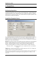
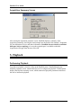
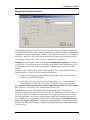
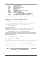
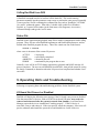
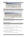
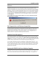
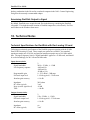
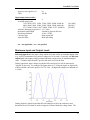
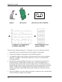
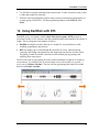
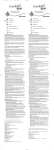
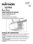
1
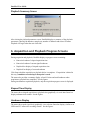
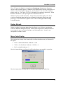
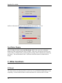
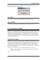
DartDisk
tm
Direct-to-disk Recorder
User Guide
Version 3.0
May, 2007
Engineering Design
This document is provided for the sole purpose of operating the DartDisk system. No part of
this document may be reproduced, transmitted, or stored by any means, electronic or mechanical.
It is prohibited to alter, modify, or adapt the software or documentation, including translating,
decompiling, disassembling, or creating derivative works. This document contains proprietary
information which is protected by copyright. All rights are reserved.
ENGINEERING DESIGN MAKES NO WARRANTY OF ANY KIND WITH REGARD TO
THE MATERIAL CONTAINED HEREIN, INCLUDING, BUT NOT LIMITED TO, IMPLIED
WARRANTIES OF MERCHANTABILITY AND FITNESS FOR A PARTICULAR PURPOSE.
Engineering Design shall not under any conditions be liable for errors contained herein or for
incidental or consequential damages arising from the furnishing, performance, or use of this
material.
The information in this document is subject to change without notice.
© 2002-2007 Engineering Design, Berkeley, CA. All rights reserved.
Printed in the United States of America.
SIGNAL, Real-Time Spectrogram, RTS, Event Detector, Event Analyzer,
Experiment Maker, CBDisk, DartDisk, DTDisk, NIDisk, WaveDisk are trademarks
of Engineering Design.
The following are service marks, trademarks, and/or registered trademarks of the respective
companies:
Communication Automation: Dart
Creative Technology: Audigy, Extigy
Data Translation: Open Layers
Hewlett-Packard: HP, LaserJet, and DeskJet
Measurement Computing Corp: Computer Boards
Microsoft: Windows, Windows 95, Windows 98, Windows 2000, Windows XP
National Instruments: NI-DAQ, NI-DAQmx
Engineering Design
262 Grizzly Peak Blvd
Berkeley, CA 94708 USA
Tel/fax 510-524-4476
Email [email protected]
www.engdes.com
LICENSE AGREEMENT
THIS IS A LEGAL AGREEMENT BETWEEN ENGINEERING
DESIGN AND THE BUYER. BY OPERATING THIS SOFTWARE,
THE BUYER ACCEPTS THE TERMS OF THIS AGREEMENT.
1. Engineering Design (the "Vendor") grants to the Buyer a non-exclusive license to operate
the provided software (the "Software") on ONE computer system at a time. The Software
may NOT reside simultaneously on more than one computing machine.
2. The Software is the exclusive property of the Vendor. The Software and all
documentation are copyright Engineering Design, all rights reserved. The Software may be
duplicated ONLY for archival back-up.
3. The Software is warranted to perform substantially in accordance with the operating
literature for a period of 30 days from the date of shipment.
4. EXCEPT AS SET FORTH IN THE EXPRESS WARRANTY ABOVE, THE
SOFTWARE IS PROVIDED WITH NO OTHER WARRANTIES, EXPRESS OR
IMPLIED. THE VENDOR EXCLUDES ALL IMPLIED WARRANTIES, INCLUDING,
BUT NOT LIMITED TO, IMPLIED WARRANTIES OF MERCHANTIBILITY AND
FITNESS FOR A PARTICULAR PURPOSE.
5. The Vendor's entire liability and the Buyer's exclusive remedy shall be, at the Vendor's
SOLE DISCRETION, either (1) return of the Software and refund of purchase price or (2)
repair or replacement of the Software.
6. THE VENDOR WILL NOT BE LIABLE FOR ANY SPECIAL, INDIRECT, OR
CONSEQUENTIAL DAMAGES HEREUNDER, INCLUDING, BUT NOT LIMITED TO,
LOSS OF PROFITS, LOSS OF USE, OR LOSS OF DATA OR INFORMATION OF ANY
KIND, ARISING OUT OF THE USE OF OR INABILITY TO USE THE SOFTWARE. IN
NO EVENT SHALL THE VENDOR BE LIABLE FOR ANY AMOUNT IN EXCESS OF
THE PURCHASE PRICE.
7. This agreement is the complete and exclusive agreement between the Vendor and the
Buyer concerning the Software.
Table of Contents
1. Overview............................................................................ 1
2. Installation......................................................................... 2
3. Operation........................................................................... 3
4. Acquisition ........................................................................ 4
5. Playback ............................................................................ 6
6. Acquisition and Playback Progress Screens ................ 8
7. Other Functions................................................................ 10
8. Command Line Mode ....................................................... 11
9. Operating Hints and Troubleshooting ............................ 13
10. Technical Notes .............................................................. 16
11. Using DartDisk and SIGNAL.......................................... 19
12. Using DartDisk with RTS ............................................... 21
1. Overview
DartDisktm provides direct-to-disk data acquisition and playback using the Dart PCMCIA
analog I/O card from Engineering Design. Program capabilities include:
• Recording and playback of 1 or 2 channels at up to 50 kHz sample rate
• 16-bit resolution on acquisition and playback
• Built-in anti-alias filter on acquisition and playback
• Programmable input gain up to 22.5 dB
• Recording and playback duration up to the capacity of the hard disk
• Records and plays sound data in either SIGNAL or Wave file format
• Runs under Windows 95/98/2000/XP
DartDisk supports the Dart PCMCIA card, but this card can be installed in a desktop using a
PCMCIA adapter. Sample applications include:
• Use with a notebook computer to perform continuous data acquisition in the field,
replacing an expensive digital recorder
• Use with a notebook computer to perform field playbacks
• Use with a desktop computer to provide an I/O workstation for streaming data
collection in the lab, for later analysis in SIGNAL or RTS
DartDisk can store acquired data in either SIGNAL or Wave file format. Both file types can
be read directly into SIGNAL or RTS for display and analysis. Applications for DartDisk
sound files within the SIGNAL family include:
• Review, measure, and edit sound data in the RTS
• Produce continuous spectrograms in SIGNAL
• Automatically analyze recorded files for sound events using the Event Detector
• Read file segments into SIGNAL for precision display and measurement
DartDisk User Guide
DartDisk does not require SIGNAL in order to operate - it can be installed on any Windows
95/98/2000/XP computer for stand-alone data acquisition.
For technical specifications on the Dart card, see the SIGNAL for Notebooks User Guide,
available from Engineering Design.
2. Installation
To install DartDisk, perform these steps in the following order:
1. Install the Dart system driver and Dart card.
2. Install the DartDisk software.
Install the Dart System Driver and Dart Card
Instructions for installing the Dart system driver and Dart card are provided in Appendix C of
the SIGNAL Reference Guide.
The Dart card uses different system drivers for Windows 95/98 vs. Windows 2000/XP.
Be sure to follow the instructions in that section for your operating system.
Install DartDisk
After installing the Dart system driver and Dart card, follow these steps to install DartDisk.
1. Launch the setup file dartdisk_xxx_setup.exe (where xxx is the version number) by
double-clicking on the filename in Windows Explorer. If you received a zip file,
extract dartdisk_xxx_setup.exe from the zip file, then launch it.
2. Follow the installation prompts.
3. Install DartDisk in the same directory as SIGNAL. The default SIGNAL program
directory is c:\Program Files\Engineering Design\Signal 4.0.
Enable SIGNAL Security Key
DartDisk requires a SIGNAL security key which has been licensed for DartDisk. If DartDisk
reports a non-licensed security key, contact Engineering Design, and the key can be enabled
by email.
2
DartDisk User Guide
DartDisk User Guide
The DartDisk User Guide (this document) is installed as a PDF (Portable Document Format)
file in the \docs directory under the SIGNAL root directory (normally c:\Program
Files\Engineering Design\Signal 4.0). PDF files require the Acrobat Reader program from
Adobe Corporation for viewing. If not already installed, this program is available for free
download at http://www.adobe.com/products/acrobat/readstep.html. Acrobat Reader is also
required by Help | User Guide on the DartDisk menu.
Acrobat Reader provides full text search capability, which can be extremely useful as a
"super-index", to find all occurrences of a particular word or phrase in the document. To
perform a text search, select Edit | Find in the Acrobat menu.
This guide can be accessed from the DartDisk menu at Help | User Guide.
3. Operation
Connecting Signals to the I/O board
See Appendix D, "I/O Hardware Connections" in the SIGNAL Reference Guide for
important notes on connecting signals to the I/O board.
Starting DartDisk
To execute DartDisk, do any of the following:
•
Click on the DartDisk desktop icon
•
Select DartDisk from the Start menu or Programs menu
•
In Windows Explorer, navigate to the folder containing the DartDisk executable, then
click on dartdisk.exe
To execute DartDisk from a DOS window, select Start | Programs | Accessories | Command
Prompt, change to the folder containing the DartDisk executable (type "cd <foldername>"),
then enter the desired DartDisk command line (see "Command line mode" below).
3
DartDisk User Guide
4. Acquisition
Performing Acquisition
To perform an acquisition, select I/O | Acquire on the DartDisk menu. DartDisk displays the
Acquisition parameter screen, which allows the user to configure the acquisition. DartDisk
then displays the Acquisition summary screen, which summarizes acquisition parameters and
allows the user to initiate the acquisition.
Acquisition Parameter Screen
The Acquisition parameter screen allows the user to specify acquisition duration, sample rate,
input gain, number of channels, the name or prefix, file type, and channel format of the
datafile to receive the acquired data, optional overwrite of pre-existing datafiles and optional
alarm sounds. These are described here.
Duration is specified in seconds, and is limited only by the available space on the destination
disk drive. Note: DartDisk does not check for sufficient disk space for your requested
duration. Acquisition length in seconds is related to disk space in MB as follows. For
example, at 50 kHz sample rate, 30 minutes of sound will require 170 MB of disk space.
Disk space in MB = (Acquisition length in secs) * (sample rate in Hz) * (no. channels)
/ 525,000
Sample rate is selected from the drop list of available sample rates in Hz. See "Sample rate
selection" below for a list of available sample rates.
Gain specifies the gain applied to the input signal before digitizing, and is specified in dB. It
is selected from the drop list of available gains, which range from 0 to 22.5 dB in 1.5 dB
increments.
4
DartDisk User Guide
No. channels can be set to 1 or 2. Maximum sample rate is unaffected by the number of
channels selected.
Filename specifies the destination sound file. If the filename does not include a full path
(drive letter and directory), files are stored in the directory containing DartDisk. Embedded
spaces are allowed in the filename. DartDisk will append the ".wav" extension to Wave files
if not included.
For a one-channel acquisition, Filename simply specifies the name of the destination sound
file.
For a multi-channel acquisition, the Filename specification depends on the Channel format
setting. With "One file per channel" (the recommended setting), specify the File prefix and
DartDisk will store the data, one file per channel, in SIGNAL files prefix.1, prefix.2, etc. or
Wave files prefix.1.wav, prefix.2.wav, etc. File prefixes should not end with a period (.).
With "Multi-channel file", specify the Filename and DartDisk will store all acquisition
channels in this file (see Channel format). Note that multi-channel SIGNAL files require
SIGNAL 5, and Wave files with more than 2 channels may require special software.
File type may be SIGNAL or Wave. Sound data are written as 16-bit integers, coded as
follows. SIGNAL files are strongly recommended.
•
SIGNAL files are written in the native 12-bit or 16-bit coding of the installed I/O
board, with offset removed from 16-bit data. A conversion factor is stored in the file
header that allows SIGNAL to reconstruct the original voltage range.
•
Wave files are written in 16-bit coding (0 offset, ±32768 range), independent of the
installed I/O card. Offset is removed and 12-bit data are scaled to 16 bits. Files are
uncompressed, i.e., in the "PCM" or "type 1" standard Wave file format.
•
Note that Wave file amplitudes may not scale correctly in SIGNAL, since the
Wave header contains no conversion factor to indicate the original voltage range
of the data.
•
Note also that Wave files with sample rates other than 44,100 Hz may not be
playable on all systems.
Channel format indicates how to store multi-channel acquisition data. One channel per file
stores each acquisition channel in a different file (see Filename above). Multi-channel file
stores all channels in one file, interleaved. For example, a 2-channel acquisition will store
point 1 of channel 1, point 1 of channel 2, point 2 of channel 1, point 2 of channel 2, etc.
Overwrite allows DartDisk to overwrite pre-existing data files of the same name without
warning the user. If Overwrite is not checked, DartDisk will request permission before
overwriting.
Dart model specifies the Dart model installed in the current system, according to its
maximum sample rate of 50, 48, or 44.1 kHz. See "Sample rate selection" below for a list of
the sample rates available for each model.
5
DartDisk User Guide
Acquisition Summary Screen
After closing the acquisition parameter screen, DartDisk displays a summary of the
acquisition parameters, showing the actual sample rate, the name of the channel 1 destination
file, the destination file size, and other information. DartDisk does not check for sufficient
disk space before acquiring, so be sure the required space is available on the disk.
Acquisition will begin when the user clicks OK.
5. Playback
Performing Playback
To perform a playback, select I/O | Play on the DartDisk menu. DartDisk displays the
Playback parameter screen, which allows the user to configure the playback. DartDisk then
displays the Playback summary screen, which summarizes playback parameters and allows
the user to initiate the playback.
6
DartDisk User Guide
Playback Parameter Screen
The Playback parameters screen allows the user to specify the file to be played, triggering
mode and optional alarm sounds. Other parameters such as duration, sample rate and number
of channels are predetermined by the sound file. The playback file may be a 1- or 2-channel
SIGNAL or Wave file. Wave files must be stored in uncompressed 16-bit coding (0 offset,
±32768 range), which is the "PCM" or "type 1" standard Wave file format.
Filename specifies the name of the file to be played, including file extension (e.g., myfile.1
or myfile.wav). If the filename does not include a full path (drive letter and directory), files
are played from the directory containing DartDisk. Embedded spaces are allowed in the
filename.
DartDisk accepts SIGNAL integer-format files and Wave files, but not SIGNAL floatingpoint format files. SIGNAL files are strongly recommended.
•
SIGNAL files are played at their original voltage range, using a conversion factor
stored in the SIGNAL file header.
•
Wave files are played using an assumed voltage range of ±3 Volts (the default for
Wave hardware), which may or may not be the original voltage range of the data.
To perform a multi-channel playback, submit a multi-channel SIGNAL or Wave sound
file. SIGNAL 5 is required to write multi-channel SIGNAL files.
Dart model specifies the Dart model installed in the current system, according to its
maximum sample rate of either 50 kHz or 44.1 kHz. See "Sample rate selection" below for a
list of the sample rates available for each model. If the sample rate of the specified sound
differs by more than 1 Hz from one of the available sample rates, DartDisk will allow the
user to either proceed at the nearest sample rate or abort the playback. DartDisk does not
convert the signal's sample rate – it simply plays the sound faster or slower than its native
duration. The RESAMP command in SIGNAL performs high-quality mathematical sample
rate conversion.
7
DartDisk User Guide
Playback Summary Screen
After closing the playback parameter screen, DartDisk displays a summary of the playback
parameters, showing the duration, sample rate, number of channels and source file name.
Playback will begin when the user clicks OK.
6. Acquisition and Playback Progress Screens
During acquistion and playback, DartDisk displays a progress screen containing:
•
Numerical readout of elapsed acquisition time
•
Numerical readout of current signal headroom
•
Graphical bar display of elapsed acquisition time
•
Graphical bar display of current headroom
Click Stop to halt the acquisition or playback before it completes. If acquisition is halted in
this way, sound data recorded up to that point is saved.
The meter also provides a summary display of total I/O time and total headroom when
acquistion or playback has completed. See the figures.
During simultaneous acquisition/playback, only the acquisition progress screen is displayed.
Elapsed Time Display
The meter shows elapsed acquisition or playback time graphically via a real-time linear bar
display and numerical readout. See the figures.
Headroom Display
The meter shows peak signal level graphically via a real-time linear bar display, similar to an
LED-based VU meter on a recording console. See the figures.
8
DartDisk User Guide
Like a VU meter, the display is oriented towards headroom, the parameter of greatest
concern to the recording engineer. Headroom is the dB difference between peak signal level
and the overload level of the A/D converter. Overload level is the converter's maximum
positive code, e.g., +2047 and +32767 for 12-bit and 16-bit converters, respectively. When
headroom decreases to 0, the input signal will be distorted in the A/D.
Headroom is also reported numerically. The operator can monitor display color for an
overview of headroom status and can use the numerical readout to adjust system gain
precisely, so as to maximize the signal-to-noise of the recorded signal without risking
overload distortion.
Display Refresh
During recording, the program updates the entire display every 100 msec, reporting the
worst-case headroom during that interval. Refresh interval represents a tradeoff between a
more responsive meter and system loading at very high sample rates. It may be userconfigurable in a future version.
Meter Color Display
The headroom bar changes color dynamically to indicate headroom status, as illustrated in
the figures:
•
Green = sufficient headroom: headroom > 6 dB
•
Yellow = low headroom: headroom < 6 dB but > 0
•
Red = overload: headroom = 0
Here is the meter during recording with sufficient headroom represented by a green bar:
Here is the meter after recording with low headroom represented by a yellow bar:
9
DartDisk User Guide
and here is the meter during an overload condition represented by a red bar:
Final Meter Display
After recording, the meter reports total headroom, which is the worst-case (minimum)
headroom of the signal during the entire recording. In this way, the operator can always tell
if the A/D has overloaded at any point during the recording without continuously monitoring
the display. The total headroom value is reflected in both the numerical readout and bar
display.
7. Other Functions
I/O Reset
The menu selection I/O | Reset performs a local reset, in case DartDisk malfunctions or stops
responding. It clears DartDisk status variables and status files, and resets the I/O board
10
DartDisk User Guide
driver. If I/O | Reset doesn't solve the problem, follow the troubleshooting steps in "I/O
Board Not Recognized or Not Responding".
User Guide
Select Help | User Guide to display the DartDisk User Guide (this document).
About DartDisk
Help | About DartDisk reports the DartDisk program version and creation date.
8. Command Line Mode
DartDisk can be executed directly from the DOS command line, by including all necessary
parameters with the DartDisk command. DartDisk will bypass the parameter setup screen
and summary screen and begin the I/O process immediately. Only the "Acquiring data" or
"Playing data" screen will be displayed. Command line mode can be used for convenience
(to avoid specifying parameters on the setup screen) and for automation and interfacing with
SIGNAL, as described below.
Command Line Syntax
DartDisk can be executed directly from the DOS command line, by including all necessary
parameters with the DartDisk command. DartDisk will bypass the parameter setup screen
and summary screen and begin the I/O process immediately. Only the "Acquiring data" or
"Playing data" screen will be displayed. Command line mode can be used for convenience
(to avoid specifying parameters on the setup screen) and for automation and interfacing with
SIGNAL, as described below.
Following is the command line syntax for acquisition and playback, respectively:
dartdisk a nchan duration srate gain filetype filename [chanform] [bdmodel]
dartdisk p filename [bdmodel]
where:
11
DartDisk User Guide
A or P
nchan
duration
srate
gain
filetype
filename
chanform
bdmodel
= acquisition or playback
= number of channels
= recording duration in seconds
= sample rate in Hz
= gain in dB
= file format ("s" = SIGNAL, "w" = Wave)
= filename or file prefix
= [optional] file channel format
("s" = one file per channel, "m" = multi-channel file)
= [optional] board model (44, 48 or 50) [default = 50]
Note: other program options are fixed in command line mode. Pre-existing data files of the
same name are overwritten. If the chanform argument is omitted, all channels are written to
one multi-channel datafile ("m" option).
Existing data files of the same name are automatically overwritten.
For example,
dartdisk a 2 60 50000 6 s myfile
will acquire two channels for 60 seconds at 50 kHz sample rate per channel with a gain of
6 dB, to SIGNAL-format sound files called myfile.1 and myfile.2, while
dartdisk p myfile
will play the sound file myfile.
If the filename or filename prefix (see "Acquisition Parameter Screen" above) includes
embedded spaces, enclose the entire name in quotation marks, for example:
dartdisk a 2 60 50000 6 s "\my project\myfile"
The optional parameter bdmodel specifies the base sample rate (in kHz) of the Dart model, if
different from the default 50 kHz. For example, the following performs the above acquisition
with a 44.1 kHz Dart model:
dartdisk a 2 60 50000 6 s myfile 44
Calling DartDisk from SIGNAL
DartDisk can be called from SIGNAL using the EXEC command. Include the full pathname
of the DartDisk executable, and enclose this in quotes if it contains embedded spaces, as in
the example below. Two applications are: 1) enclosing DartDisk in a SIGNAL program loop
to automate and time repetitive playbacks (using DOLOOP and TWAIT), and 2) using
TWAIT to run DartDisk at a particular time of day, for scheduled recording. The following
example (which should be presented on a single line) will perform the acquisition described
above:
EXEC "c:\Program Files\Engineering Design\Signal 4.0\dartdisk"
a 2 60 50000 6 s "\my project\myfile"
12
DartDisk User Guide
Calling DartDisk from DOS
A DartDisk command can also be run from a DOS batch file. This avoids entering
parameters manually into the parameter setup screen, to perform the same process repeatedly.
Create a one-line .bat file containing the command line text, such as "dartdisk a 2 60 50000
10 s myfile" without the quotes. Then either 1) double-click on this file in Windows
Explorer, or 2) open a DOS window (in the Start menu, click Programs | Accessories |
Command Prompt) and type the .bat file name.
Status File
DartDisk writes acquisition and playback status files to enable communication with a calling
program. These files are called DartDiskAcqStatus.txt and DartDiskPlayStatus.txt, and are
located in the DartDisk program directory. These files contain one line in the format
status = status
where status is the status of the current I/O process:
ACTIVE
DONE
ABORTED
ERROR
= in progress
= successfully completed
= aborted by the user
= terminated by the program due to error
Normally, status will be ACTIVE during acquisition or playback and DONE after the I/O
process completes. The user can call DartDisk from SIGNAL, then poll the status file (using
RA family commands) to determine when the I/O process has completed and whether it was
successful.
9. Operating Hints and Troubleshooting
Following are operating hints and troubleshooting guidelines for the DartDisk system.
I/O Board Not Present or Disabled
DartDisk will display the following error message if the I/O board is not present or disabled.
Note that removable I/O devices, such as PCMCIA cards and USB units, may need to be
removed and reinserted after the system is restored from Standby, even when Device
Manager reports the device as installed and "working properly". If the I/O device is
removable, remove and reinsert it. If the error persists, reboot the computer. If the error still
persists, uninstall and reinstall the system driver and board driver for the I/O device.
13
DartDisk User Guide
DartDisk Program Already Active or Terminated Abnormally
DartDisk may issue the following message on startup. This can occur if another DartDisk
program is running, or if a previous DartDisk process terminated abnormally and is running
invisibly. To check for an invisible DartDisk, open Task Manager (Ctl-Alt-Del), search for
dartdisk.exe, and terminate the process if present.
Minimum and Maximum Duration
Minimum acquisition and playback duration is 0.1 seconds. Maximum acquisition and
playback duration is the capacity of the hard disk.
Sample Rate Selection
All Dart cards provide 8 sample rates ranging between a maximum sample rate and (max
sample rate)/6. The standard model provides a maximum sample rate of 50 kHz, with the
following sampe rate choices:
8333, 10000, 12500, 16667, 20000, 25000, 33333, 50000 Hz
Another model provides a maximum sample rate of 44.1 kHz for compatibility with audio
CDs, with the following sampe rate choices:
7350, 8820, 11025, 14700, 17640, 22050, 29400, 44100 Hz
Another model provides a maximum sample rate of 48 kHz for compatibility with DAT
audio, with the following sampe rate choices:
8000, 9600, 12000, 16000, 19200, 24000, 32000, 48000 Hz
14
DartDisk User Guide
I/O Errors
Acquisition and playback errors arise when the I/O board cannot convert data, or when
DartDisk cannot cannot store or retrieve data from memory or the hard disk, at the requested
sample rate. DartDisk will issue the following message. Possible causes include performing
demanding processes in parallel with DartDisk, a slow CPU, or a slow hard disk. Remedies
are to terminate other processes, defragment the hard disk, increase CPU or disk capabilities,
or reduce sample rate. DartDisk may also fail if the progress window is moved on the
screen during I/O.
Note: DartDisk will save data acquired until the error, but use caution because final
data blocks may be corrupted.
Disk Fragmentation and Maximum Sample Rate
On older hard disks, fragmentation can degrade the maximum sample rate. Disks can be
defragmented by clicking My Computer | Files | Properties | Tools | Defragment Now in
Windows 95/98 or My Computer | Local Disk | Properties | Tools | Defragment Now in
Windows 2000/XP. This process should be performed with care.
Notebook Power Management
Some notebook computers (such Toshiba models) optionally reduce processor speed when
running from batteries, to conserve battery life. This can reduce the maximum achievable
sample rate. To avoid this, reconfigure the computer’s power management program (usually
available from the Control Panel) to run at full processor speed on battery power.
As an example, following are steps for reconfiguring a Toshiba Satellite 2250CDT: 1) run
Power Saver from the Control Panel (not the Windows-supplied Power Management utility),
2) in the "Running on batteries" section, set the power mode to High Power, 3) click Details,
select the Power Save Mode tab, and move the 4 slider controls associated with Processor
Speed to Full, 4) click OK.
Running the PCMCIA Card from a Desktop Computer
A PCMCIA card can be run from a desktop computer using a PCMCIA to PCI adapter card.
This card costs under $200 and can allow the card to do "double duty", for example, in a
15
DartDisk User Guide
desktop workstation in the lab and in a notebook computer in the field. Contact Engineering
Design for the currently recommended adapter.
Examining DartDisk Output in Signal
By default, DartDisk stores acquired sound files in the directory containing the DartDisk
executable. If in doubt about the location of DartDisk output files, select Search | For Files
and Folders on the Windows Start menu.
10. Technical Notes
Technical Specifications for DartDisk with Dart analog I/O card
Following are technical specifications of the DartDisk program operating with the 50 kHz
Dart PCMCIA analog I/O card. Three sample rate options are available – the standard
maximum sample rate of 50 kHz, and optional maximum sample rates of 44.1 kHz and 48
kHz. The upper frequency limit in "Signal bandwidth" applies to a 50 kHz card, and should
be scaled accordingly for 44.1 kHz and 48 kHz cards.
Input characteristics
Maximum channels
Signal bandwidth
Low frequency response
Programmable gain
Full-scale input level
Absolute gain accuracy
2
20 Hz - 23 kHz, ± 1.5 dB
-4 dB at 8 Hz
-8 dB at 4 Hz
-20 dB at 1 Hz
0 – 22.5 dB in 1.5 dB steps
1.4 Volts typical, 1.5 Volts max
± 1.0 dB
Impedance
DC offset (typical)
Noise (re max signal level)
THD
20 K ohms
3 mV
-81 dB
< -90 dB
Output characteristics
Maximum channels
Signal bandwidth
Full-scale output level
Absolute gain accuracy
Impedance
DC offset (typical)
16
2
5 Hz - 22 kHz, ± 1.5 dB
1.4 Volts typical, 1.55 Volts max
± 1.0 dB
n/s
3 mV
DartDisk User Guide
Noise (re max signal level)
THD
n/s
-80 dB
Input/output characteristics
No. sample rates
8
Available sample rates
7350, 8820, 11025, 14700, 17640, 22050, 29400, 44100 Hz
8000, 9600, 12000, 16000, 19200, 24000, 32000, 48000 Hz
8333, 10000, 12500, 16667, 20000, 25000, 33333, 50000 Hz
Absolute (damaging) signal level ± 2.5 Volts
Maximum signal length
Limited by physical disk size
Digitizing resolution
16-bit = 96 dB
Converter type
Delta-sigma 64X
Anti-alias filter
Built-in tracking
[44.1 kHz]
[48 kHz]
[50 kHz]
n/a = not applicable, n/s = not specified
Maximum Input and Output Levels
Full-scale input level is the input voltage which drives the card to its maximum digital value
(e.g., 0x7FFF hexadecimal for a positive voltage to a 16-bit card). Conversely, the full-scale
output level is the output voltage produced when the card processes its maximum digital
value. "Technical Specifications" specifies full-scale levels for the Dart.
During acquisition, input voltages beyond the full-scale input level will be truncated or
"clipped" by the card. For example, the figure shows a 1.6 Volt peak signal, as digitized by
a Dart card with a full-scale input level of 1.4 Volts. All digitized voltages are truncated at ±
1.4 Volts.
During playback, signals beyond the full-scale output level drive the card into a more
disastrous form of overload, in which voltages are reflected about the voltage limits. The
17
DartDisk User Guide
figure shows the effect of a small overload, in which a 1.6-Volt signal is played through a
Dart card with a full-scale output level of 1.55 Volts.
Full-scale input and output levels vary somewhat between individual Dart cards. To avoid
accidental overload, DartDisk assumes the same minimum full-scale level for all cards. Card
variation produces input and output gain errors of < 1 dB. If this error is not significant or
you are not concerned with absolute sound levels, you can skip the remainder of this
discussion.
For example, a Dart card with a nominal full-scale input level of 1.4 Volts and an actual fullscale level of 1.5 Volts will produce a digitized signal whose amplitude is 1.4/1.5 = 93% of
the true input level. Thus a 1-Volt peak input signal will be digitized (and displayed in
SIGNAL) with a peak level of 0.93 Volts.
Similarly, a Dart card with a nominal full-scale output level of 1.4 Volts and an actual fullscale level of 1.5 Volts will deliver analog output signals whose amplitude is 1.5/1.4 = 107%
of their nominal output level. Thus a 1-Volt peak signal (created for example in SIGNAL)
would be delivered with a peak level of 1.07 Volts.
Absolute Gain Accuracy
Absolute input gain accuracy expresses the deviation in dB between the digital amplitude
level reported by the Dart card and the analog input level presented to the card for digitizing.
Similarly, output gain accuracy represents the deviation between the digital signal level
presented for playback and the analog output level delivered by the card.
Gain accuracy depends on the manufacturing process and therefore varies slightly between
units. Gain accuracy is another way of expressing the variation in full-scale input and output
levels discussed in "Maximum Input and Output Levels" above. Dart cards have a specified
input and output gain accuracy of ±1.0 dB. Dart cards are currently shipped with an input
gain calibration factor, which can be used to adjust acquired levels when highly accuracte
absolute input levels are required.
18
DartDisk User Guide
Low-Noise Operation
Low-noise operation is important when acquiring low-level signals. The essential concept is
signal-to-noise ratio (S/N or SNR), which is the dB ratio of the input signal to the effective
input noise (EIN) of the Dart card. S/N should be maximized. When a signal's S/N falls
below 50-60 dB (depending on source material), the noise component becomes audible to
most human subjects.
EIN mathematically expresses the aggregate noise contribution of all internal noise sources,
referred to the device input. S/N is the ratio of input signal level to EIN. The principal Dart
noise sources are 1) input noise of the programmable gain amplifier and 2) effective noise of
the digitizer. Amplifier noise is about 12 uV-RMS or -98 dB re full-scale (1.4 Volts peak).
Digitizer noise is about 2 bits, which translates to –84 dB re full-scale or 60 uV-RMS.
Therefore at 0 dB programmable input gain, EIN will be dominated by digitizer noise, while
at gains > 20 dB, EIN will be dominated by amplifier noise. So EIN decreases as
programmable gain increases, and for optimal low-noise operation, use the maximum
input gain possible without saturating (clipping) the input signal.
Following are typical EIN values, measured at 0 dB and 19.5 dB programmable gain. EIN re
full-scale represents the card's maximum S/N capability at that gain setting. Nominal fullscale voltage for the Dart is ±1.4 Volts.
EIN (uVolts-RMS)
EIN (dB re full scale)
Gain = 0 dB
60 uV
-84 dB
Gain = 19.5 dB
12 uV
-98 dB
11. Using DartDisk and SIGNAL
DartDISK can be used in conjunction with the SIGNALtm sound analysis program to record
extended acoustic data sequences, then locate and analyze the sound events within them.
This section describes the overall approach, basic tools, and important information sources.
The two programs work together as follows:
•
DartDisk provides long-duration high-frequency direct-to-disk recording, producing long
continuous sound files in the SIGNAL or Wave sound file format.
•
SIGNAL can display the entire sound file (see below), which the researcher can use as a
roadmap to extract specific sound events. SIGNAL can manually extract, display,
measure, and analyze these events and store them as individual sound files. SIGNAL can
also be programmed to perform acoustic measurements automatically on the stored
events.
19
DartDisk User Guide
Subject
Microphone
Continous sound spectrogram
in SIGNAL using STRIP
Record sound file in DartDisk
Edit and measure sound
events in SIGNAL
The above figure illustrates this process. Following is an overview of the steps involved.
1. Present the acoustic vocalization stream to the microphone or hydrophone.
2. Connect the microphone or hydrophone to the DartDisk input panel.
3. Use DartDisk to digitize and record the vocalization stream to one or more continuous
sound files. Normally, set the DartDisk sample rate to at least 2.5 times the desired
recording bandwidth.
4. Start SIGNAL and use the STRIP command to view a continuous spectrogram of the
recorded sound file. STRIP produces a multi-screen "strip-chart" frequency-time
spectrogram with typically 30-60 seconds of sound per screen. This allows the user to
navigate through a long recording, spotting sound events and extracting them for detailed
analysis. Settings such as frequency range and spectrogram resolution can be used to
customize the display. Note: STRIP settings can be collected in a SIGNAL macro for
convenience.
5. After using STRIP to review the sound file and locate vocalization events, read individual
events into SIGNAL using the R /Q command.
20
DartDisk User Guide
6. Use SIGNAL to measure and analyze the sound events. Events can also be saved on disk
as individual sound files if desired.
7. SIGNAL can be programmed to perform many acoustic measurements automatically on
an entire group of sound files. See the programming chapters in the SIGNAL User
Guide
12. Using DartDisk with RTS
DartDISK can be used together with the Real-Time Spectrogramtm (RTS) program to
record and visually review, measure, and edit extended acoustic data sequences up to hours in
length. The two programs work together as follows:
•
DartDisk can digitize an entire data tape to a sound file, or perform direct-to-disk
recording, bypassing the tape entirely.
•
RTS can rapidly page or scroll through the sound file on-screen, while measuring,
extracting, and storing sound parameters and sound segments directly from the screen.
Navigating a sound file on disk is much more efficient than playing, pausing, and
replaying from a tape player!
The RTS can scroll or page rapidly forward or backward through a sound file to search for
events interest. For example, this 30-second sample screen was scrolled in 3 seconds – a
review rate of 10 times real-time! The user can also page through the sound file in either
direction at 15 times real-time.
21
DartDisk User Guide
The wide screen and high-resolution spectrogram of the RTS can be used to locate events in
sparse data sets. For example, the sparse sound file in the figure was displayed in 5-minute
segments, in which the 3 events are clearly visible. With 3 seconds to draw or scroll a new
screen, this allows sparse data sets to be analyzed at 100 times real-time. Once located,
individual events can be zoomed for close examination.
22
DartDisk User Guide
The RTS runs within SIGNAL, so sound segments can be transferred easily to SIGNAL
buffers for immediate analysis, and measured sound parameters can be stored in the SIGNAL
logfile. In the figure, the RTS has saved 6 events in SIGNAL buffers and 11 measurement
records have been stored in the SIGNAL logfile. Events can also be stored as SIGNAL,
Wave, or AIFF sound files for later analysis.
23