1
OPERATOR'S MANUAL
CLEAN BURN MODEL: CB-1400
MULTI-OIL FURNACE
with CB-525-S2 BURNER
U.L. Listed Used Oil
Burning Appliance
#MH15393 (N)
U.L.-C Listed
#CMP217
I88817
PUBLICATION DATE: 8/15/07, Rev. 3
CLEAN BURN PART # 43204
WARNING: DO NOT assemble, install, operate, or maintain this equipment without first
reading and understanding the information provided in this manual. Installation and
service must be accomplished by qualified personnel. Failure to follow all safety precautions
and procedures as stated in this manual may result in property damage, serious personal injury
or death.
IMPORTANT FOR U.S. INSTALLATIONS: All installations must be made in accordance with state and local codes
which may differ from the information provided in this manual. Save these instructions for reference.
IMPORTANT FOR CANADIAN INSTALLATIONS: These instructions have been reviewed and accepted by
Underwriters' Laboratories of Canada as being appropriate for the installation of the ULC labelled products
identified herein. The use of these instructions for the installation of products NOT bearing the ULC label and
NOT identified herein may result in an unacceptable or hazardous installation.
IMPORTANT FOR CANADIAN INSTALLATIONS: The installation of this equipment is to be accomplished by
qualified personnel and in accordance with the regulation of authorities having jurisdiction and CSA Standard B 139,
Installation Code for Oil Burning Equipment.
WARRANTY INFORMATION
Clean Burn, Inc., MANUFACTURER, hereby warrants that MANUFACTURER's products shall be free from defect in
material and workmanship under normal use according to the provisions and limitations herein set forth.
MANUFACTURER warrants the heat exchanger/combustion chamber for a period of ten (10) years (or 15,000 hours,
whichever comes first), from the date of purchase by the purchaser, as follows:
If the defect occurs in the first five (5) years (or 7500 hours, whichever comes first) , Clean Burn pays 100% of parts,
replacement or repair (the customer pays 0%), and pro rata thereafter according to the following schedule:
(a) If the defect occurs during the sixth year (or 7500-9000 hours, whichever comes first), customer pays 70% of
parts, replacement or repair.
(b) If the defect occurs during the seventh year (or 9000-10,500 hours, whichever comes first), customer pays 75%
of parts, replacement or repair.
(c) If the defect occurs during the eighth year (or 10,500-12,000 hours, whichever comes first), customer pays 80%
of parts, replacement or repair.
(d) If the defect occurs during the ninth year (or 12,000-13,500 hours, whichever comes first), customer pays 85% of
parts, replacement or repair.
(e) If the defect occurs during the tenth year (or 13,500-15,000 hours, whichever comes first), customer pays 90% of
parts, replacement or repair.
MANUFACTURER warrants all other Clean Burn component parts, including the energy retention disk, for a period of
one (1) year from the date of purchase by the purchaser.
LIMITATIONS:
The obligation of MANUFACTURER for breach of warranty shall be limited to products manufactured by MANUFACTURER (1) that are
installed, operated and maintained according to MANUFACTURER's instructions furnished and/or available to the purchaser upon request;
(2) that are installed according to all other applicable Federal, State and local codes or regulations; and (3) that the purchaser substantiates
were defective in material and workmanship notwithstanding that they were properly installed and correctly maintained as set forth above and
were not abused or misused.
The obligation of MANUFACTURER shall be limited to replacing or repairing the defective product, at the option of the
MANUFACTURER. MANUFACTURER shall not be responsible for any labor or costs of removal or reinstallation of its products and
shall not be liable for transportation costs to and from its plant at Leola, Pennsylvania.
Use of parts for modification or repair of the product or any component part thereof not authorized or manufactured by
MANUFACTURER specifically for such product shall void this warranty.
This warranty shall not apply to any damage to or defect in any of MANUFACTURER's products that is directly or indirectly caused by
(1) force majeure, Act of God or other accident not related to an inherent product defect; or (2) abuse, misuse or neglect of such product,
including any damage caused by improper assembly, installation, adjustment, service, maintenance or faulty instruction of the purchaser.
Other than as expressly set forth hereinabove, MANUFACTURER makes no other warranty, express or implied, with respect to any of
MANUFACTURER's products, including but not limited to any warranty of merchantability or fitness for a particular purpose.
And in no event shall MANUFACTURER be responsible for any incidental or consequential damages of any nature suffered by purchaser or
any other person or entity caused in whole or in part by any defect in any of MANUFACTURER's products. Any person or entity to whom
this warranty extends and who claims breach of warranty against MANUFACTURER must bring suit thereon within one year from the date
of occurrence of such breach of warranty or be forever barred from any and all legal or other remedies for such breach of warranty.
MANUFACTURER is not responsible for and hereby disclaims any undertaking, representation or warranty made by any dealer,
distributor or other person that is inconsistent with or in any way more expansive than the provisions of this limited warranty.
This warranty grants specific legal rights and shall be read in conformity with applicable state law. In some jurisdictions, the applicable law
mandates warranty provisions that provide greater legal rights than those provided for herein. In such case, this limited warranty shall be read
to include such mandated provisions; and any provision herein that is prohibited or unenforceable in any such jurisdiction shall, as to such
jurisdiction, be ineffective to the extent of such prohibition or unenforceability without invalidating the remaining provisions and without
affecting the validity or enforceability of such provision in any other jurisdiction(s).
TRADEMARKS
The Clean Burn logo is a trademark of Clean Burn, Inc. All other brand or product names mentioned are the registered
trademarks or trademarks of their respective owners.
COPYRIGHT
Copyright © 2007 Clean Burn, Inc. All rights reserved. No part of this publication may be reproduced, or distributed without
the prior written permission of Clean Burn, Inc. 34 Zimmerman Road, Leola, PA 17540. Subject to change without notice.
TABLE OF CONTENTS
SECTION 1: INTRODUCTION .................................................................................... 1-1
Guide to this Manual ........................................................................................................ 1-1
For Your Safety ................................................................................................................ 1-2
Guidelines for Furnace Usage ................................................................................... 1-4
Guidelines for Used Oil Tanks .................................................................................. 1-5
Safety Labels ............................................................................................................. 1-6
SECTION 2: UNPACKING.......................................................................................... 2-1
Removing the Shipping Pallet .......................................................................................... 2-1
Unpacking and Inspecting All Components .................................................................... 2-1
Furnace Component List ........................................................................................... 2-1
Warranty Registration ...................................................................................................... 2-2
SECTION 3: FURNACE ASSEMBLY ......................................................................... 3-1
Understanding Assembly ................................................................................................. 3-1
Required Tools and Materials ................................................................................... 3-1
Installing the Observation Port......................................................................................... 3-2
Installing the Fan Assembly ............................................................................................. 3-3
Installing the Burner ......................................................................................................... 3-4
Checking the Burner Nozzle and Electrodes............................................................. 3-4
Mounting the Burner on the Hinge Bracket .............................................................. 3-5
Installing the Connector Block, Oil Line Tubing, and Air Line Tubing .......................... 3-6
Installing the Connector Block on the Furnace Cabinet ........................................... 3-6
Installing the Oil Line Tubing ................................................................................... 3-6
Installing the Air Line Tubing ................................................................................... 3-7
Locking the Burner into Firing Position .................................................................... 3-8
SECTION 4: FURNACE INSTALLATION ................................................................... 4-1
Understanding Installation ............................................................................................... 4-1
Selecting a Location ......................................................................................................... 4-3
Guidelines for Selecting a Location .......................................................................... 4-3
Mounting the Furnace ...................................................................................................... 4-4
Ceiling Mounting ...................................................................................................... 4-4
Raised Platform Mounting ........................................................................................ 4-5
Floor Mounting .......................................................................................................... 4-5
Oil Tank Installation Specifications ................................................................................ 4-7
Installing the Tank Vent and Emergency Vent ......................................................... 4-8
Installing the Metering Pump ........................................................................................... 4-9
Preparing for Installation ........................................................................................... 4-9
Standard Mounting: Vertical Position ....................................................................... 4-9
Alternate Mounting: Horizontal Positioning ........................................................... 4-11
Wiring the Furnace and Pump ........................................................................................ 4-12
Wiring to the Furnace .............................................................................................. 4-12
Wiring to the Metering Pump .................................................................................. 4-12
Installing the Suction Oil Line Components .................................................................. 4-13
TABLE OF CONTENTS
SECTION 4: FURNACE INSTALLATION (continued)
Installing the Pressure Relief and Low-Flow Check Valve ........................................... 4-16
Installing the Pressure Oil Line Components ................................................................. 4-17
Installing the Compressed Air Line ............................................................................... 4-17
Installing the Stack ......................................................................................................... 4-18
Stack Design and Specifications ............................................................................. 4-18
Installing the Interior Stack ..................................................................................... 4-21
Installing the Barometric Damper ........................................................................... 4-21
Installing the Stack Safety Switch For Canadian Installations................................ 4-22
Resetting the Stack Safety Switch ..................................................................... 4-23
Understanding the Function of the Stack Safety Switch ................................... 4-23
Installing the Stack Penetration ............................................................................... 4-24
Installing the Exterior Stack .................................................................................... 4-24
Installing the Stack Cap........................................................................................... 4-24
Installing the Optional Draft Inducer ...................................................................... 4-24
Installing the Wall Thermostat ....................................................................................... 4-26
Inspecting the Furnace Installation ................................................................................ 4-26
SECTION 5: METERING PUMP PRIMING ................................................................ 5-1
Understanding Metering Pump Priming .......................................................................... 5-1
Required Tools and Materials ................................................................................... 5-1
Preparing the Burner for Use with the Metering Pump ................................................... 5-2
Priming the Metering Pump ............................................................................................. 5-4
Vacuum Testing the Oil Pump ......................................................................................... 5-6
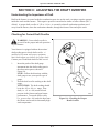
SECTION 6: STARTING AND ADJUSTING THE BURNER ...................................... 6-1
Understanding Burner Startup and Adjustment ............................................................... 6-1
Preparing the Burner for Startup ...................................................................................... 6-1
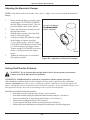
Starting the Burner ........................................................................................................... 6-3
Checking the Operation of the Fan Motor ....................................................................... 6-4
SECTION 7: RESETTING THE OIL PRIMARY CONTROL ....................................... 7-1
Understanding the Oil Primary Control ........................................................................... 7-1
Using the Reset Button..................................................................................................... 7-1
SECTION 8: ADJUSTING THE DRAFT OVER FIRE ................................................. 8-1
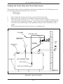
Checking for Correct Draft Over Fire .............................................................................. 8-1
Adjusting the Barometric Damper ................................................................................... 8-2
Solving Draft Overfire Problems ..................................................................................... 8-2
Understanding the Effect of Exhaust Fans on Draft.................................................. 8-3
Checking Draft Overfire to Determine Severity of Backdraft .................................. 8-3
Installing a Make-up Air Louver ............................................................................... 8-5
TABLE OF CONTENTS
SECTION 9: MAINTENANCE ..................................................................................... 9-1
Understanding Maintenance ............................................................................................ 9-1
Periodic Burner Inspection ............................................................................................... 9-2
Cleaning the Canister Filter ............................................................................................. 9-3
Servicing the Metering Pump........................................................................................... 9-4
Cleaning the Check Valve and Check Valve Screen ....................................................... 9-5
Cleaning the Tank ............................................................................................................ 9-6
Cleaning Ash from the Furnace ....................................................................................... 9-6
Annual Burner Tune-up ................................................................................................... 9-9
End of Season Maintenance ............................................................................................. 9-9
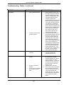
SECTION 10: TROUBLESHOOTING ....................................................................... 10-1
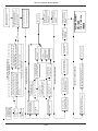
Flow Chart ...................................................................................................................... 10-2
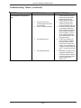
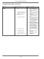
Troubleshooting Tables.................................................................................................. 10-3
APPENDIX A
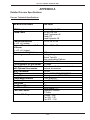
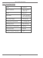
Detailed Furnace Specifications ..................................................................................... A-1
Furnace Technical Specifications ............................................................................ A-1
Burner Technical Specifications .............................................................................. A-2
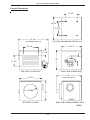
Furnace Dimensions ................................................................................................. A-3
Burner Components .................................................................................................. A-4
Cleaning the Nozzle ........................................................................................... A-9
Fan Limit Control ................................................................................................... A-10
APPENDIX B
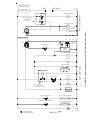
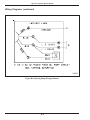
Wiring Diagrams ............................................................................................................. B-1
Furnace Wiring Diagram .......................................................................................... B-1
Burner Wiring Diagram ............................................................................................ B-2
CB-1400 Ladder Schematic ..................................................................................... B-3
Metering Pump Wiring Schematic ........................................................................... B-4
APPENDIX C
Furnace Service Record .................................................................................................. C-1
Operator's Manual: Model CB-1400
SECTION 1: INTRODUCTION
Guide to this Manual
This manual contains all the information necessary to safely install and operate the Clean Burn Furnace Model
CB-1400. Consult the Table of Contents for a detailed list of topics covered. You'll find this manual's step-bystep procedures easy to follow and understand. Should questions arise, please contact your Clean Burn dealer
before starting any of the procedures in this manual.
As you follow the directions in this manual, you'll discover that assembling and operating your new
furnace involves five basic activities as outlined here:
•
•
•
•
•
UNPACKING ....................................................................................................
ASSEMBLY ......................................................................................................
INSTALLATION .............................................................................................
OPERATION
• Metering Pump Priming ......................................................................
• Starting and Adjusting the Burner .....................................................
• Resetting the Furnace and Burner ......................................................
• Adjusting the Draft ...............................................................................
MAINTENANCE .............................................................................................
The manual also contains important and detailed technical
reference materials which are located at the back of the
manual in the Appendixes.
(Section 2)
(Section 3)
(Section 4)
(Section 5)
(Section 6)
(Section 7)
(Section 8)
(Section 9)
WARNING!
Please read all sections carefully--including the important
safety information found in this section--before beginning
any installation/operation procedures; doing so ensures
your safety and the optimal performance of your Clean
Burn furnace.
STOP
YOUR SAFETY IS AT STAKE!
DO NOT INSTALL, OPERATE OR
MAINTAIN THIS EQUIPMENT
WITHOUT FIRST READING
AND UNDERSTANDING THE
OPERATOR'S MANUAL!
1-1
Operator's Manual: Model CB-1400
For Your Safety...
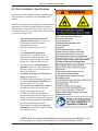
For your safety, Clean Burn documentation contains the following types of safety statements (listed here
in order of increasing intensity):
•
NOTE: A clarification of previous information or additional pertinent information.
•
ATTENTION: A safety statement indicating that potential equipment damage may occur if
instructions are not followed.
CAUTION: A safety statement that reminds of safety practices or directs attention to unsafe
practices which could result in personal injury if proper precautions are not taken.
WARNING: A strong safetystatement indicating that a hazard exists which can result in
injury or death if proper precautions are not taken.
DANGER! The utmost levels of safety must be observed; an extreme hazard exists which
would result in high probability of death or irreparable serious personal injury if proper
precautions are not taken.
In addition to observing the specific precautions listed throughout the manual, the following general
precautions apply and must be heeded to ensure proper, safe furnace operation.
DANGER! DO NOT create a fire or explosion hazard by storing or using gasoline or other
flammable or explosive liquids or vapors near your furnace.
DANGER! DO NOT operate your furnace if excess oil, oil vapor or fumes have
accumulated in or near your furnace. As with any oil burning furnace, improper installation,
operation or maintenance may result in a fire or explosion hazard.
WARNING: DO NOT add inappropriate or hazardous materials to your used oil, such as:
• Anti-freeze
• Carburetor cleaner
• Paint thinner
• Parts washer solvents
• Gasoline
• Oil additives
• Any other inappropriate/hazardous
material
WARNING: Burning chlorinated materials (chlorinated solvents and oils) is illegal, will
severely damage your heat exchanger, immediately void your warranty, and adversely affect
the proper, safe operation of your furnace. Instruct your personnel to never add hazardous
materials to your used oil.
1-2
Operator's Manual: Model CB-1400
For Your Safety... (continued)
WARNING: Never alter or modify your furnace without prior written consent of
Clean Burn, Inc. Unauthorized modifications or alteration can adversely affect the proper,
safe operation of your furnace.
WARNING: The burner which is shipped with your Clean Burn furnace is to be used only
with your furnace according to the instructions provided in this manual. DO NOT use the
burner for any other purpose!
WARNING: The Best Operator is a Careful Operator! By using common sense,
observing general safety rules, and adhering to the precautions specific to the equipment, you,
the operator, can promote safe equipment operation. Failure to use common sense, observe
general safety rules, and adhere to the precautions specific to the equipment may result in
equipment damage, fire, explosion, personal injury and/or death.
WARNING: The installation, operation, and maintenance of this equipment in the U.S.
must be accomplished by qualified personnel and in compliance with the specifications in the
Clean Burn Operator's Manual and with all national, state, and local codes or authorities
having jurisdiction over environmental control, building inspection and fuel, fire and
electrical safety and the following standards:
NFPA 30
Flammable and Combustible Liquids Code
NFPA 30A Automotive and Marine Service Station Code
NFPA 31
Standard for the Installation of Oil Burning Equipment
NFPA 211
Chimneys, Fireplaces, Vents and Solid Fuel Burning Appliances
NFPA 88A Parking Structures
NFPA 88B
Repair Garages
NFPA 70
National Electrical Code
The International Mechanical Code
The International Building Code
The International Fire Code
The International Fuel Gas Code
Likewise, the installation, operation, and maintenance of this equipment in Canada is to be
accomplished by qualified personnel and in compliance with the specifications in the
Clean Burn Operator's Manual and in accordance with the regulation of authorities having
jurisdiction and the following CSA Standards:
B139
B140.0
C22.1
Installation Code for Oil Burning Equipment
General Requirements for Oil Burning Equipment
Canadian Electrical Code, Part 1
Failure to comply with these standards and requirements may result in equipment
damage, fire, explosion, personal injury and/or death.
1-3
Operator's Manual: Model CB-1400
For Your Safety... (continued)
Guidelines for Furnace Usage
•
This furnace is listed for commercial and/or industrial use only; it is not listed for residential use.
•
This furnace is listed with Underwriters Laboratory (UL) and Underwriters' Laboratories of
Canada (ULC) to burn the following fuels:
• Used crankcase oil up to 50 SAE
• Used transmission fluid
• Used hydraulic oils
• #2 fuel oil
• #4 fuel oil
• #5 fuel oil
NOTE: Used oils may contain other substances, including gasoline, that may hinder
performance.
•
Make sure you comply with all EPA regulations concerning the use of your furnace. EPA
regulations require that:
• Your used oil is generated on-site. You may also accept used oil from
"do-it-yourself" oil changers.
• Hazardous wastes, such as chlorinated solvents, are NOT to be mixed with your
used oil.
• The flue gases are vented to the outdoors with an appropriate stack.
• Your used oil is recycled as fuel for "heat recovery". DO NOT operate your furnace
in warm weather just to burn oil.
Contact your Clean Burn dealer for current EPA regulations.
•
If your furnace ever requires service, call your Clean Burn dealer. DO NOT allow
untrained, unauthorized personnel to service your furnace. Make sure that your furnace
receives annual preventative maintenance to ensure optimal performance.
1-4
Operator's Manual: Model CB-1400
For Your Safety... (continued)
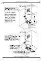
Guidelines for Used Oil Tanks
For the safe storage of used oil and the safety of
persons in the vicinity of the used oil supply tank,
ensure that your tank installation adheres to the
following safety guidelines:
•
•
•
•
The tank installation must meet all
national and local codes. Consult your
local municipal authorities for more
information as necessary.
Review and adhere to the safety
guidelines for used oil supply tanks
as stated in the WARNING shown.
Ensure that the tank for your furnace
installation complies with all code and
safety requirements as stated here. If the
tank does not comply, DO NOT use it.
If you do not have a copy of the tank
safety label pictured at right, please
contact your Clean Burn dealer for the
label, which is to be affixed directly on
your used oil supply tank.
1-5
Operator's Manual: Model CB-1400
For Your Safety... (continued)
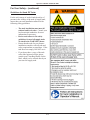
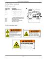
Safety Labels
Following are the locations and descriptions of all labels on your CB-1750 or CB-2501 furnace. The following
illustrations show the location of ALL labels on your furnace. Please note that some labels denote model
number, model description, etc. while others contain important safety messages.
Each Safety Label contains an important safety message starting with a key word as discussed earlier in
this section (e.g. ATTENTION, CAUTION, WARNING, DANGER). For your safety and the safe
operation of your furnace, review all labels and heed all safety messages as printed on the labels.
If any labels on your Clean Burn furnace ever become worn, lost or painted over, please call your Clean
Burn dealer for free replacements.
42171
AIR
OIL
CB-1400 Furnace Cabinet Labels
Label Part #
42030
42027
42171
42197
42137
42045
42176
42367
42068
Description
Furnace Electrical Shock Hazard Warning Label
Furnace Burn Hazard/Hazardous Voltage Warning Label
UL Data Label - CB-1400
Patent Pending Label
Date Code Label
Made in USA Label
Model CB-1400 Label
Furnace Safety Warning Label (Multiple Messages - Fire/Shock/Burn Hazards)
Furnace Blower/Fan Entanglement Hazard Warning Label (near fan)
1-6
Operator's Manual: Model CB-1400
For Your Safety... (continued)
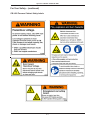
CB-1400 Furnace Cabinet Safety Labels
1-7
Operator's Manual: Model CB-1400
For Your Safety... (continued)
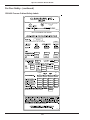
CB-1400 Furnace Cabinet Safety Labels
MH 15393
UNDERWRITERS’ LABORATORIES
OF CANADA
LISTED
NO.
10523
MULTI−OIL BURNING UNIT HEATER
CB 1400
INPUT RATING W/NO 2 FUEL OIL (BTU/HR)
1.0
140000
15.0
1.5
1.0
15.0
2.0
1.0
15.0
1.5
1.0
15.0
1.5
.04
18
18
60
24
36
24
24
POWER
HZ
1/3
120
5.3
60
1/20
120
0.75
60
1/10
120
1.4
60
400
120
3.3
60
1/3
120
3.9
60
1/3
120
3.5
60
18.2
MAXIMUM FUSE SIZE / WITH OPTIONS
20/30
FOR COMMERCIAL OR INDUSTRIAL USE ONLY.
42171
1-8
Operator's Manual: Model CB-1400
For Your Safety... (continued)
CB-1400 Burner Labels
Label Part #
42005
42004
42000
42235
42321
42197
42229
42023
Description
Sold and Serviced By Label
Burner Safety Warning Label
(High Voltage/Moving Parts Hazards)
Burner Safety Warning Label
(Fire/Explosion Hazard - Reset Button)
Burner Safety Warning Label
(Fire/Explosion Hazard Burner Installation and Service)
Burner Model/Serial Number Label
Patent Pending Label
Logo/Burner Description Label
Burner Power Label
42197
42321
I88603
CB-1400 BurnerSafety Labels
1-9
Operator's Manual: Model CB-1400
1-10
Operator's Manual: Model CB-1400
SECTION 2: UNPACKING
Before assembling your furnace, you must accomplish the following activities described in this section:
• Removing the Shipping Crate
• Unpacking and Inspecting All Components
• Warranty Registration
Removing the Shipping Crate
ATTENTION: Remove the shipping crate prior to assembly and installation of the furnace. DO NOT use the
pallet as a platform for furnace installation!
1.
2.
Carefully remove the top boards of the shipping crate. Then remove the front, back, and side panels of
the shipping crate.
Carefully lift the furnace off the shipping pallet with a fork lift, and discard the pallet.
NOTE: DO NOT attempt to slide the furnace out of the shipping crate - you may damage the furnace cabinet.
Unpacking and Inspecting All Components
Following is an itemized list of all components you should have received in your Clean Burn furnace
shipment. Open all shipping containers and inspect all components according to the list. Immediately
notify the freight company and your Clean Burn dealer in case of shipping damage or shortage(s). Keep
all components together so you will have them as needed for furnace assembly and installation.
Furnace Component List
ONE SKID containing:
• Furnace Cabinet
• Burner
• Oil Pump
• Accessory Box (includes the following):
• Canister Filter
• Vacuum Gauge
• Check Valve and Check Valve Screen
• Wall Thermostat
• Barometric Damper
• Connector Block
• Burner Oil Line and Air Line Components
• Assorted bolts/fittings for assembly/installation of furnace components
• Operator's Manual Literature Packet (includes Tank Safety Label)
NOTE: You may have received additional boxes or skids if you ordered optional accessories.
2-1
Operator's Manual: Model CB-1400
Warranty Registration
For proper warranty registration, Clean Burn requires that you fill out the provided warranty registration
card and return it within 30 days to:
CLEAN BURN WARRANTY REGISTRATION
Clean Burn, Inc.
34 Zimmerman Road
Leola, Pennsylvania 17540
2-2
Operator's Manual: Model CB-1400
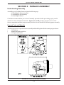
SECTION 3: FURNACE ASSEMBLY
Understanding Assembly
Assembling your Clean Burn Furnace includes the following steps:
(1) Installing the Observation Port
(2) Installing the Fan Assembly
(3) Installing the Burner
Clean Burn recommends that you review all assembly procedures before proceeding, paying careful
attention to safety information statements. Figures 3A and 3B provide a general overview of the
furnace components and their proper assembly and how the unit should look following proper assembly.
Required Tools and Materials
The following tools are required for furnace assembly and should be gathered before starting any procedures:
•
1/4" nut driver
•
Medium flat-blade screwdriver
•
9/16" open-end wrench
FIGURE 3A - Overview of Furnace Assembly
3-1
Operator's Manual: Model CB-1400
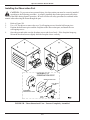
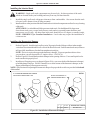
Installing the Observation Port
CAUTION: To prevent serious personal injury, the observation port must be correctly installed
according to the following procedure. A properly installed observation port permits safe observation of the flame during furnace operation. Be sure to follow all safety procedures as outlined in this
manual when observing the flame through the port.
1.
2.
3.
4.
Refer to Figure 3B.
Use a 1/4" nut driver to remove the two (2) self-tapping screws from the half-moon piece.
Position the half-moon piece and the faceplate on the observation port, and install the two
self-tapping screws.
Open the port and make sure the faceplate moves and closes freely. If the faceplate hangs up,
loosen the hex-head screws slightly until the faceplate closes correctly.
ASSEMBLY OF
OBSERVATION PORT
OBSERVATION PORT
HALF−MOON
PIECE
ASSEMBLED
OBSERVATION PORT
FACE
PLATE
FIGURE 3B - Three-dimensional View - Furnace Completely Assembled
3-2
Operator's Manual: Model CB-1400
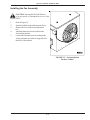
Installing the Fan Assembly
CAUTION: Ducting the CB-1400 Furnace
is not permitted; it is intended for use as a Unit
Heater ONLY.
1.
2.
3.
4.
5.
Refer to Figure 3C.
Spin the fan blade to check that it spins freely.
Remove the cover of the electrical junction
box.
Attach the fan motor electrical cable to the
electrical junction box.
Connect the fan motor wires according to the
wiring schematic provided in Appendix B at
the back of the manual.
FIGURE 3C - Fan Installed on
Furnace Cabinet
3-3
Operator's Manual: Model CB-1400
Installing the Burner
Checking the Burner Nozzle and Electrodes
NOTE: The burner nozzle, a Delavan 9-5, is factory installed. The nozzle size is indicated on the
nozzle as shown in Figure 3D. Refer also to Appendix A at the back of the manual for additional
specifications/instructions on the burner nozzle.
ATTENTION: Check the electrode settings as specified in Figure 3D. The electrode settings must be
correct for your burner to operate properly.
BURNER NOZZLE
NOZZLE IS STAMPED EITHER 9−5
OR −5 ON FLAT OF NOZZLE HEAD
SIDE VIEW − AA
3/16" GAP BETWEEN
ELECTRODES & NOZZLE
3X
CRITICAL DIMENSIONS:
ELECTRODES MUST BE
FLUSH WITH NOZZLE TIP.
RETENTION HEAD DISK MUST
BE FLUSH WITH NOZZLE TIP
VIE
W
−B
B
W
VIE
A
−A
1/8"
SPARK
GAP
SIDE VIEW − BB
Figure 3D - Burner Nozzle and Electrode Specifications
3-4
I88340
Operator's Manual: Model CB-1400
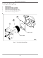
Installing the Burner (continued)
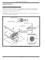
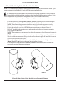
Mounting the Burner on the Hinge Bracket
ATTENTION: Burner tube components (e.g. electrodes and retention head) are factory set. Handle the
burner with extreme care so that burner components are not damaged.
1.
Remove the nut from the bolt on the mounting flange of the furnace cabinet with a 9/16" open-end
wrench, and set it aside for later use.
2.
Lift the burner into position so the burner hinge plate is mounted on the hinge bracket on the
furnace cabinet as shown in Figure 3E.
3.
Carefully swing the burner so the retention head enters the throat of the furnace.
4.
Check the clearance between the retention head and the furnace throat. There must be at least
1/8" clearance, so the retention head is not "bumped" as you swing the burner into firing
position.
NOTE: If the retention head "bumps" the furnace throat, adjust the hinge bracket bolts
as follows:
• While supporting the burner, slightly loosen the two (2) hinge bracket bolts.
• Carefully re-position the burner so it swings freely into its firing position.
• With the burner in its firing position, re-tighten the hinge bracket bolts.
5.
Install and tighten the lock-down nut on the mounting plate bolt to secure the burner in its firing
position.
I88823
Figure 3E - Mounting the Burner
3-5
Operator's Manual: Model CB-1400
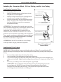
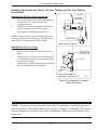
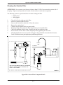
Installing the Connector Block, Oil Line Tubing, and Air Line Tubing
Installing the Connector Block
1.
2.
3.
4.
Refer to Figure 3F.
Install the mounting bracket on the furnace cabinet
using the two (2) bolts supplied.
Install the connector block on the mounting bracket
using the two (2) carriage bolts supplied.
Remove and discard the red caps and plugs from the
fittings and ports on the connector block. DO NOT
allow any dirt/debris to enter these components
during furnace assembly.
ATTENTION: The connector block includes an accumulator.
The accumulator functions like a shock absorber on the oil line
to prevent pressure buildup and protect vital burner
components. It is important that the connector block is
installed as shown so that the accumulator is in a vertical
position to prevent sediment from settling in the accumulator.
Never operate your furnace without the connector block and
accumulator properly installed on the furnace, or damage
may occur to vital burner components.
ATTENTION: DO NOT use teflon tape on any fittings.
Teflon tape residues will plug vital burner components.
SWIVEL ASSEMBLY
MOUNTING BRACKET
CONNECTOR BLOCK
AIR
OIL
DETAIL OF MOUNTING BRACKET AND
CONNECTOR BLOCK
MOUNTING BRACKET
CONNECTOR BLOCK
AIR
OIL
DETAIL OF OIL LINE AND AIR LINE
INSTALLED
I88824
Figure 3F - Installation of
Connector Block
Installing the Oil Line Tubing
NOTE: DO NOT disassemble the compression fitting from the swivel fitting. To prevent leaks, the NPT
threads of the compression fitting have been sealed with hydraulic sealant during assembly of the fittings at the
factory.
1.
Remove and discard the red caps from the oil line tubing.
2.
Loosely install the oil line tubing into the oil line fitting on the burner.
3.
Use a wrench to slightly rotate the oil line fitting on the burner counterclockwise so the tubing lines up
with the swivel assembly. Slightly bend the tubing as shown in Figure 3G, if required, to "line up" the oil
line.
4.
If necessary, use a tubing cutter to cut the tubing to the proper length.
ATTENTION: Due to adjustment of the burner hinge bracket, the oil line tubing may need to
be cut to fit properly. DO NOT lift up on the burner when installing the oil line tubing to
compensate for oil line tubing that is too long. This will place the weight of the burner on the
swivel fitting and result in leaks at the swivel fitting seal.
3-6
Operator's Manual: Model CB-1400
Installing the Connector Block, Oil Line Tubing, and Air Line Tubing
(continued)
OIL LINE
Installing the Oil Line Tubing (continued)
5.
6.
OIL FITTING
ON BURNER
Make sure that the curl in the oil line is positioned as
shown in Figure 3L so that the burner can
swing open correctly.
Install the oil line tubing and tighten the nuts on the
compression fittings. DO NOT overtighten
these fittings to avoid damaging the ferrules.
NOTE: You may also check the positioning of the oil line
according to Figure 3H on the next page which provides a
larger front view of the connector block assembly.
CONNECTOR BLOCK
AIR
OIL
FRONT VIEW OF FURNACE
Installing the Air Line Tubing
1.
2.
3.
Remove and discard the red caps from the air line
tubing.
Refer to Figure 3H. Push the air line tubing into the
swivel fitting on the connector block until the tubing
bottoms out in the fitting.
Repeat this procedure to connect the air line tubing to
the air line fitting on the side of the burner.
OIL LINE FITTING
ON BURNER LINED
UP WITH OIL LINE
OIL LINE
SWIVEL
ASSEMBLY
CONNECTOR
BLOCK
SIDE VIEW OF FURNACE
SHOWING OIL LINE INSTALLED
I88825
Figure 3G - Installation of Connector
Block and Oil Line
NOTE: Your furnace is now assembled and ready for installation. Install the furnace as
soon as possible so the burner and/or blower are not "bumped" or damaged. If you must
store the furnace for a period of time before installation, make sure it is located in a safe,
secure area.
3-7
Operator's Manual: Model CB-1400
Installing the Connector Block, Oil Line Tubing, and Air Line Tubing
(continued)
AIR LINE FITTING
ON BURNER
OIL LINE FITTING
ON BURNER
AIR LINE
OIL LINE
COMPRESSION/
SWIVEL FITTING
AIR
OIL
CONNECTOR BLOCK INSTALLED
ON FURNACE CABINET
Figure 3H - Installation of Connector Block, Oil Line, and Air Line (Front View)
Locking the Burner into Firing Position
1.
2.
3.
4.
Swing the burner into firing position.
Install and tighten the lock-down nut on the mounting
plate bolt to secure the burner in its firing position.
Plug the burner electrical cable into the receptacle on the
top of the burner housing.
Tighten the locking ring to secure the electrical cable.
NOTE: Be sure to properly align the plug when plugging it into
the receptacle. See Fig 3I.
CONNECTOR PLUG
KEY IN PLUG
MUST ALIGN
WITH SLOT IN
RECEPTACLE
RECEPTACLE ON
TOP OF BURNER
I88641−B
Figure 3I - Detail of Burner
Electric Receptacle
3-8
Operator's Manual: Model CB-1400
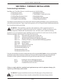
SECTION 4: FURNACE INSTALLATION
Understanding Installation
Installing your Clean Burn furnace is a multi-step process which includes:
(1) Selecting a Location
(6) Installing the Oil Lines
(2) Mounting the Furnace
(7) Installing the Compressed Air Line
(3) Oil Tank Specifications (review)
(8) Installing the Stack
(4) Installing the Metering Pump
(9) Installing the Wall Thermostat
(5) Wiring the Furnace and Pump
(10) Inspecting the Installation
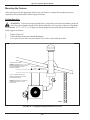
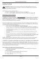
Clean Burn recommends that you review all procedures before beginning installation, paying careful attention to
safety information statements. Figure 4A provides a general overview of a typical furnace installation and should
be reviewed closely before proceeding.
WARNING: The installation, operation, and maintenance of this equipment in the U.S.
must be accomplished by qualified personnel and in compliance with the specifications in the
Clean Burn Operator's Manual and with all national, state, and local codes or authorities having
jurisdiction over environmental control, building inspection and fuel, fire and electrical safety and the
following standards of the National Fire Protection Association.
NFPA 30
Flammable and Combustible Liquids Code
NFPA 30A
Automotive and Marine Service Station Code
NFPA 31
Standard for the Installation of Oil Burning Equipment
NFPA 211
Chimneys, Fireplaces, Vents and Solid Fuel Burning Appliances
NFPA88A
Parking Structures
NFPA 88B
Repair Garages
NFPA 70
National Electrical Code
The International Mechanical Code
The International Building Code
The International Fire Code
The International Fuel Gas Code
Likewise, the installation, operation, and maintenance of this equipment in Canada is to be accomplished by
qualified personnel and in compliance with the specifications in the Clean Burn Operator's Manual and in
accordance with the regulation of authorities having jurisdiction and the following CSA Standards:
B139
B140.0
C22.1
Installation Code for Oil Burning Equipment
General Requirements for Oil Burning Equipment
Canadian Electrical Code, Part 1
Failure to comply with these standards and requirements may result in equipment damage, fire,
explosion, personal injury and/or death.
WARNING: Improper installation can adversely affect the proper, safe operation of your
furnace. It is critical that your furnace installer reads and follows the instructions provided in
this manual.
4-1
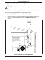
10 FT.
OIL PUMP ELECTRICAL CIRCUIT
PRESSURE OIL LINE
CAUTION: DO NOT EXCEED 6 FT VERTICAL
SUCTION LIFT OR THE PUMP WILL NOT
PRIME AND/OR THE FLOW RATE FROM
THE PUMP MAY DECREASE
ELECTRIC SERVICE
COMPRESSED AIR LINE
MAXIMUM 6 FT.
24 VOLT WALL
THERMOSTAT
AIR INTAKE
8 FT. MIN. FROM FLOOR TO FURNACE IFTHERE IS A POTENTIAL FOR
GASOLINE FUMES IN YOUR SHOP. CHECK LOCAL CODES AND NFPA 88−B
"2 WIRE" MIN 18 GA.
THERMOSTAT CABLE
DEDICATED ELECTRIC CIRCUIT
1/4" HOLE FOR
SETTING DRAFT.
ADJUST BAROMETRIC
DAMPER FOR −.04" W.C.
DRAFT AT BREECH
10 FT. MINIMUM VERTICAL STACK HEIGHT PLUS 1 FT. FOR
EVERY FITTING TO MAINTAIN PROPER DRAFT OVERFIRE
2 FT.
Operator's Manual: Model CB-1400
WARNING: When installing your furnace,
adhere to the minimum clearances from
combustible surfaces as stated in Section 4.
These clearances also provide adequate
space for servicing. Failure to maintain
proper clearances may result in fire,
explosion, personal injury, or death.
BALL VALVE
SUCTION
OIL LINE
VENT
CAP
EMERGENCY
VENT VALVE
OIL
STORAGE
TANK
CLEANOUT
WITH DRAIN
I88827
Figure 4A - Typical Furnace Installation
4-2
Operator's Manual: Model CB-1400
Selecting a Location
Guidelines for Selecting a Location
The location you select for your furnace must allow the following:
• Unobstructed, even heat distribution.
• Safe, easy access for servicing.
• Unobstructed passage for shop vehicles and equipment.
• Proper clearances from combustibles. Verify according to your local safety codes.
• Adequate combustion air per local codes.
• Proper stack installation.
WARNING: Adhere to the following minimum clearances from combustible surfaces which
will also provide adequate clearance for servicing (Figure 4B); failure to maintain proper clearances
may result in fire, explosion, personal injury or death.
TOP ....................................... 18"
FRONT (burner side) ............ 24"
REAR (stack side) ................ 36"
LOUVER SIDE ..................... 60"
FAN SIDE ............................. 24"
BOTTOM .............................. 96"
CHIMNEY CONNECTOR .. 18"
18 "
CHIMNEY
CONNECTOR
TOP
18 "
24 "
FAN SIDE
WARNING: National
codes require that your
furnace is mounted a minimum of
eight (8) feet off the ground when
installing the furnace in a repair
facility. Refer to NFPA-88B,
Standard for Repair Garages,
Chapter 3, Hazards, Sec. 3-2.3-1.
36 "
REAR
60 "
LOUVER SIDE
24 "
FRONT
I88828
96 " BOTTOM − IF THERE IS POTENTIAL
FOR GASOLINE FUMES
24 " BOTTOM − IF THERE IS NO POTENTIAL
FOR GASOLINE FUMES
FIGURE 4B - Clearances from Combustibles
4-3
Operator's Manual: Model CB-1400
Mounting the Furnace
After selecting a safe and appropriate location for your furnace, construct the mounting system as
required by the location and the following specifications.
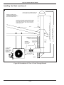
Ceiling Mounting
WARNING: To prevent serious personal injury, ensure that your furnace mounting system can
safely bear the suspended weight of the furnace and allow safe servicing of furnace components.
Use minimum 2-1/2" x 2-1/2" x 1/4" angle iron beams bridged across sufficient structural members to
safely support the furnace.
1.
2.
3.
Refer to Figures 4C.
Follow the instructions as provided in the diagram.
Use a spirit level to make sure the cabinet is level side to side and front to back.
CEILING MOUNTING SYSTEM
WARNING! USE MINIMUM 2−1/2 X 2−1/2 X 1/4" ANGLE
IRON BEAMS, BRIDGED ACROSS SUFFICIENT
STRUCTURAL MEMBERS TO SAFELY
ANGLE IRON SUPPORT
SUPPORT THE FURNACE
BEAMS
DOUBLE NUTS
(4) 5/8 "ALL THREAD" SUPPORT RODS
THREAD SUPPORT RODS TO COUPLING
NUTS IN FURNACE CABINET
WARNING! MAKE SURE TO USE LOCK NUTS
WHEN FASTENING THE RODS TO THE
COUPLING NUTS
I88829
FIGURE 4C -Ceiling Mounting Installation Overview
4-4
Operator's Manual: Model CB-1400
Mounting the Furnace (continued)
Raised Platform Mounting
1.
8 FOOT MINIMUM FROM FLOOR TO FURNACE IF THERE IS
A POTENTIAL FOR GASOLINE FUMES IN YOUR SERVICE
AREA. CHECK LOCAL CODES AND NFPA 88−B
WARNING: To prevent serious personal
injury, make sure the platform is designed
to safely bear the weight of the furnace and allow
safe servicing of furnace components. The
platform must be constructed of non-combustible
materials (e.g. steel) and must be securely
anchored to an adjacent wall.
Refer to Figure 4D and follow the
instructions as provided in the diagram.
Floor Mounting
WARNING: To prevent serious personal
injury, make sure the floor can safely bear the
weight of the furnace.
CAUTION: If you are installing your furnace
in an area with a combustible floor (e.g. over
the top of a parts room or on a mezzanine), you must
construct a non-combustible floor as shown in Figure
4E. Refer to NFPA-31 or CSA-B-139.
I88830
FIGURE 4D - Furnace Installed on
Raised Platform
Constructing a Non-Combustible Floor
1.
Determine the size of floor you will need to construct:
• Measure the width and length of the furnace cabinet
• Add 12" (minimum) to all sides of the cabinet to achieve the total measurement for the
non-combustible floor.
The CB-1400 is approximately 34" x 30"
34" + 12" + 12" = 58"
30" + 12" + 12" = 54"
Therefore your non-combustible floor will need to be 58" x 54"
2.
Refer to Figure 4E. Install two (2) pieces of 5/8" sheet rock on top of the combustible material
(wooden floor, wooden beams, etc.) The sheet rock must be cut to the size of the total
non-combustible floor area.
Place a sheet of 24-gauge (minimum) galvanized sheet metal on top of the 5/8" sheet rock;
the sheet metal must cover the sheet rock completely.
Place 4" thick (minimum) hollow masonry block, end to end, on top of the 24-gauge sheet metal
to make a solid foundation. Be sure to add center cross blocking to safely and adequately support
the furnace.
3.
4.
4-5
Operator's Manual: Model CB-1400
Constructing a Non-Combustible Floor (continued)
5.
6.
7.
8.
Place a 24-gauge sheet metal pan with a 1" containment lip on top of the masonry blocks. This
will provide containment of any oil that may be spilled while working on the furnace.
Position the furnace on top of the sheet metal pan; make sure you maintain the extra 12"
minimum clearance on all sides of the cabinet.
Ensure that the installation adheres to all clearances from combustibles as stated at the beginning
of Section 4 in this manual.
After positioning the furnace cabinet on the sheet metal pan, install 2" tall (minimum) cinder
blocks (4) under each corner of the furnace to elevate the cabinet off the sheet metal pan to allow
clearance for installation of fittings on the connector block.
MIN. 12"
MIN. 24 GA STEEL
PAN WITH MIN. 1 INCH
LIP FOR OIL
CONTAINMENT
MIN. 12"
4 INCHES (MIN.)
TALL CINDER BLOCK
1 PIECE
MIN. 24 GA STEEL
2 PIECES 5/8" SHEETROCK
COMBUSTIBLE MATERIAL
MIN. 4" TALL MASONRY BLOCKS TO ALLOW
CLEARANCE FOR INSTALLATION OF
FITTINGS ON THE CONNECTOR BLOCK
Figure 4E - Furnace Installed on Non-Combustible Floor
4-6
I88831
Operator's Manual: Model CB-1400
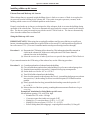
Oil Tank Installation Specifications
Ensure that your tank installation adheres to the following
safety guidelines as stated here and in Section 1 of this
manual.
The tank safety label (shown at right) also summarizes these
important specifications for tank installation and usage. If
you do not have a copy of this label, please contact your
Clean Burn dealer for a copy, which is to be affixed directly
to your used oil supply tank.
•
•
•
•
•
•
•
•
•
The tank installation must meet all
national and local codes. Consult your
local municipal authorities for more
information as necessary.
The tank must be listed to UL 80 or
UL 142.
Use a minimum 250-gallon tank.
DO NOT use a 55-gallon drum as a
substitute for an appropriate tank. The
tank must be large enough to allow water,
sludge, etc. to settle out of the used oil.
The tank must have a manual shut-off
type valve on the side of the tank to allow
the water, sludge, etc. to be drained from
the bottom of the tank.
All unused openings in the tank must be
plugged or capped off.
For optimal system functioning, Clean Burn
recommends inside tank installations as
shown in Figures 4A, 4F, and 4J.
The tank must be vented to the outside of
the building using iron or steel pipe and
fittings with an approved vent cap.
Carefully review the oil tank and pump
installation details as shown in Figures 4A, 4F,
and 4J. Pertinent information is also supplied
with the metering pump and oil line installation
procedures (following in Section 4).
Ensure that the oil supply tank is properly
maintained; refer to Section 9 in this manual
for related procedures.
ATTENTION: For outside tank installations and/or tanks larger than 500 gallon, contact
the Clean Burn Service Department for installation recommendations and specifications.
4-7
Operator's Manual: Model CB-1400
Oil Tank Installation Specifications (continued)
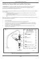
TANK VENT KITS AVAILABLE FROM CLEAN BURN:
CB Part # 70380 − 4" Tank Vent Kit
(2) elbows
(2) 6" nipples
(1) mushroom cap vent
(1) emergency vent
PUMP
MUSHROOM
CAP VENT
STEEL PIPE
(USER SUPPLIED)
SUCTION LINE
ASSEMBLY
FUNNEL WITH
BALL VALVE
EMERGENCY
VENT
CHECK
VALVE
FILTER
SCREEN
CLEAN−OUT
(TANK DRAIN)
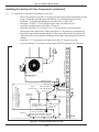
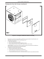
FIGURE 4F - Typical Metering Pump Installation with Inside Tank
Installing the Tank Vent and Emergency Vent
National codes require that you install a tank vent (to the outside) and an emergency vent for your tank
as shown in Figure 4F. Tank Vent Kits are available from Clean Burn; contact your local Clean Burn
dealer to order. Be sure to check your local codes for any additional tank installation requirements, and
adhere to the following installation guidelines:
• Install a length of minimum 2" steel pipe (user-supplied) terminating outside with a proper
vent cap as shown in Figure 4F. Consult local codes for information and requirements
concerning the proper venting of oil storage tanks.
• Install an emergency vent as shown in Figure 4F. Contact your tank manufacturer for
information concerning the proper emergency vent for your tank.
4-8
Operator's Manual: Model CB-1400
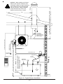
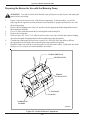
Installing the Metering Pump
Preparing for Installation
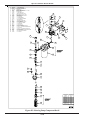
Before starting installation of the metering pump, review Figure 4G, 4H, and 4I to become familiar with the
metering pump components. You will also need to accomplish the following activities:
• Verify that you have the proper metering pump for your furnace model.
• Gather all required tools and materials as needed for installation; as indicated in the
following procedures, some materials (e.g. fittings, tubing) are to be user-supplied.
• Standard mounting is vertical mounting on a wall; this pump installation is recommended.
Alternate mounting is horizontal mounting on a bracket. Be sure to carefully follow the
appropriate procedures/diagrams for pump mounting.
• For optimal metering pump functioning, ensure that the pump is mounted at a distance not
more than four (4) feet from the oil tank.
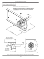
Standard Mounting: Vertical Positioning
1.
2.
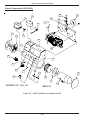
Refer to Figures 4G, 4H, and 4I. Note that the metering pump is shipped with the pump head
already positioned for vertical wall mounting.
Use the appropriate type of bolts and washers (user-supplied) to securely mount the metering
pump to the appropriate wall in your building at a distance not more than four feet from the tank.
Figure 4G - Vertical Mounting of the Metering Pump
4-9
Operator's Manual: Model CB-1400
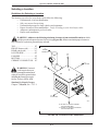
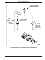
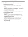
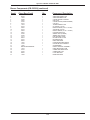
#
PART #
1
2
3
4
5
6
7
8
9
10
11
12
13
14
15
16
17
18
19
20
21
22
23
24
25
26
27
28
29
33363
see chart
11322
32062
32293
32425
32424
32335
21119
32327
32467
32210
32336
32123
32127
32430
32446
32429
32137
32142
32062
32443
32141
32140
32139
32442
32021
32061
32445
DESCRIPTION
CAPACITOR − GEARMOTOR
GEARMOTOR
MOUNT − METER PUMP
MALE CONNECTOR 1/4" T TO 1/4" NPT
RELIEF VALVE
1/4" NPT BRASS TEE
LOW FLOW CHECK VALVE
ADAPTOR PIPE 1/4"F X 1/8"M
LID − METER PUMP HOUSING
METER PUMP
1/4" X 3" NIPPLE
1/4" STREET ELBOW
1/4" X 3/4" BRASS BUSHING
VACUUM GAUGE
CANISTER FILTER− LENZ
1/2" x 3/4" BUSHING, BRASS
1/2" X 5" NIPPLE
1/2" STREET TEE, BRASS
1/2" HEX NIPPLE
1/2" BALL VALVE
1/4" NPT x 1/4" TUBING FITTING
1/4" x 1/2" BUSHING
1/2" NPT x 1/2" TUBING FLARE ADAPTER
1/2" LONG NUT
1/2" NPT x 1/2" TUBING SLIP ADAPTER
2" x 1/2" x 1/2" NPT DUPLEX HEX BUSHING
3/4" CHECK VALVE
3/4" CHECK VALVE SCREEN
1/2" PIPE CAP
4
5
3
6
2
7
8
10
29
11
9
13
17
16
1
12
14
18
15
19
20
23
24
21
22
25
26
24
23
16
27
28
Figure 4H - Metering Pump Component Detail
4-10
CLEAN BURN
MODEL
GEARMOTOR
PART #
SATURN A2
CB−1400
CB−1750
CB−2501
CB−3500
CB−5000
CB−200−CTB
CB−350−CTB
33291
33291
33353
33354
33355
33356
33507
33295
Operator's Manual: Model CB-1400
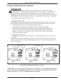
Installing the Metering Pump (continued)
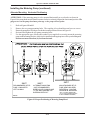
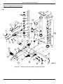
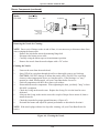
Alternate Mounting: Horizontal Positioning
ATTENTION: If the metering pump is to be mounted horizontally or on a bracket as shown in
Figure 4I, the pump head must be rotated counterclockwise so that it is aligned in a horizontal position. The
gauge arrow on the pump head must point up, or the pump will not prime.
1.
2.
3.
4.
5.
Refer to Figures 4H and 4I.
Remove the two pump mounting bolts. The coupling is keyed and does not have set screws.
Rotate the pump head 180 degrees to the horizontal position as shown in Figure 4I.
Re-install and tighten the two pump mounting bolts.
Use the appropriate type of bolts and washers (user-supplied) to securely mount the metering
pump to the mounting bracket, which is to be installed on the appropriate wall in your building at a
distance not more than four (4) feet from the tank.
ROTATION
GAUGE
INLET
GAUGE
INLET
GAUGE
INLET
INLET
INLET
INLET
ROTATION
RO TATION
RO TATION
INLET
INLET
INLET
RECOMMENDED SETUP
PUMP IS MOUNTED
LEFT ON WALL
ALTERNATE MOUNTING
(NOT RECOMMENDED)
BLEED VALVE IS NOW CLOSE
TO THE WALL MAKING THE
BLEEDING DIFFICULT
I88708
NON−STANDARD SETUP
PUMP HEAD HAS BEEN
ROTATED 90° CCW FOR
HORIZONTAL MOUNTING
(THE 1/4" STREET ELBOW AND
1/4" X 3" NIPPLE CHANGE PLACES
IN THE PLUMBING SEQUENCE)
Figure 4I - Proper Positioning of Metering Pump Head
4-11
Operator's Manual: Model CB-1400
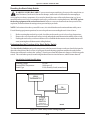
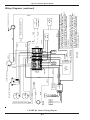
Wiring the Furnace and Pump
WARNING: To avoid electrical shock, make sure that power to the furnace is turned OFF
before connecting any wires. A licensed electrician should install all wiring to your furnace. All wiring
must be in accordance with the National Uniform Electrical Code and local codes. Properly size all wires and
use electrical conduit for all electrical lines.
Wiring your furnace involves the installation of two lines:
(1) A dedicated electrical line to the furnace
(2) A pump electrical circuit from the furnace to the metering pump
Necessary wiring specifications are provided in this section and in the Wiring Schematics located in
Appendix B at the back of the manual.
Wiring to the Furnace
1.
Install a dedicated electrical circuit to the electrical junction box on the furnace.
WARNING: DO NOT tie into an existing circuit, or electrical overload may occur.
2.
3.
Wire the furnace according to the Wiring Schematic, Figure B1, in Appendix B.
Check for correct voltage at the furnace, and refer to the following chart.
ATTENTION: Incorrect voltage will severely damage the blower motor/furnace components.
DO NOT operate your furnace on any non-specification power system.
Model
CB-1400
Voltage
110/120
Breaker Size*
20 amps
Circuit
Dedicated
Hertz
60
*NOTE: Breaker size with optional equipment is 30 amps. When installing any
optional equipment (e.g. air compressor or draft inducer), you must use a 30 amp breaker. Make
sure a qualified electrician properly sizes and installs this electrical circuit.
4.
DO NOT turn on main power until instructed to do so.
Wiring to the Metering Pump
WARNING: DO NOT wire the pump directly into your building's electrical system. The pump
must be activated (receive power) from the burner via the pump electrical circuit. DO NOT wire the
pump directly to a wall outlet so that it runs continuously; this will seriously damage your metering pump and/or
furnace and may result in a fire or explosion hazard.
1.
2.
Install the pump electrical circuit from the furnace to the metering pump location.
Wire the pump circuit according to the appropriate Wiring Schematics, Figures B1 and B4
(Appendix B).
4-12
Operator's Manual: Model CB-1400
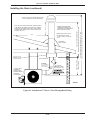
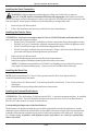
Installing the Suction Oil Line Components
ATTENTION: It is critical that you adhere to the following specifications for suction oil line
installation (oil line from the tank to the pump). If these specifications are not met, the metering pump
will not function correctly and the burner will shut down on reset. The majority of service problems with the
metering pump are caused by leaks at fittings in the suction oil line; these problems are eliminated by ensuring
a 100% airtight suction oil line which slants up to the pump.
1.
•
All suction oil line components must be installed as shown in Figures 4H and 4J. Suction line size
is 1/2" diameter. Proper installation allows the suction oil line to be filled with used oil during initial
priming.
•
The suction oil line may NOT exceed 6 feet TOTAL vertical lift AND 4 feet TOTAL
horizontal lift (which equals 6.0” hg maximum operating vacuum). To determine if your
suction oil line will meet this specification for maximum operating vacuum, base the calculation for
your installation on the following equivalents:
(1) vertical foot
= 0.75” hg (vacuum)
(4) horizontal feet
= 0.75” hg (vacuum)
NOTE: ALSO ADD 0.75" hg to the final sum to account for every oil filter, shut-off valve, and
check valve on the suction side of the pump assembly.
Sample calculation: (6) vertical feet x 0.75" = 4.50" hg AND (4) horizontal feet = 0.75" hg
4.50" hg + 0.75" hg + 0.75" hg = 6.00" hg vacuum
•
The metering pump must be installed with a 3/4" check valve and screen at the end of the
suction oil line, or the pump will not maintain its prime.
•
Use Permatex #2 non-hardening gasket sealer on every threaded fitting. DO NOT use
teflon tape or teflon pipe dope compounds; the teflon can flake off and cause damage to the
pump head.
•
The suction oil line must be 100% airtight for proper system functioning. Use only
high-quality flare fittings for the copper tubing. DO NOT use compression fittings.
DO NOT use any steel pipe unions. DO NOT use sweat copper pipe. These types of fittings
cause air leaks in the suction oil line and will require re-installation.
•
The suction oil line must slant up to the pump; any high spots will trap air and will not
allow the pump to prime.
Assemble the suction oil line fittings (from the metering pump to the canister filter):
a. Refer to Figure 4H for a detailed look at the metering pump components and fittings.
b. Remove the plug from the 1/4" inlet port of the pump.
c. Install the 1/4" x 3" brass nipple into the 1/4" inlet port on the pump.
d. Install the 1/4" brass street elbow onto the 3" brass nipple; turn the fitting onto the nipple until it is
tight and faces away from the pump mounting plate.
e. Prepare the canister filter for installation:
• Install the 3/4" x 1/4" brass hex bushing into the outlet port of the canister filter.
Check the direction of the arrow for the proper flow.
• Install the 3/4" x 1/2" brass bushing into the inlet port of the canister filter.
4-13
Operator's Manual: Model CB-1400
Installing the Suction Oil Line Components (continued)
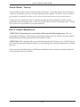
OIL PUMP ELECTRICAL CIRCUIT
(e.) Prepare the canister filter for installation (continued):
• Remove the plug from one of the 1/8" gauge ports in the canister filter and install the vacuum
gauge. Seal the threads of the gauge with Permatex #2 non-hardening gasket sealer.
• Install the 1/2" threaded pipe adapter into one side of the 1/2" ball valve.
• Install the 1/2" MPT x 1/2" flare adapter into the other side of the ball valve.
• Install this assembly into one side of the 1/2" brass tee.
• Install the assembled 1/2" tee into the 3/4" x 1/2" brass bushing, which is installed in
the inlet port of the canister filter. Make sure that the 1/2" flare adapter is pointing down.
• Install the canister filter assembly onto the 1/4" brass street elbow as shown in Figure 4H.
The canister filter must be installed with the arrow pointing towards the pump (direction of
oil flow).
• Install the 1/2" x 5" brass nipple into the top side of the 1/2" brass tee assembly.
• Loosely install the 1/2" brass cap onto this nipple; DO NOT tighten the cap at this time.
COMPRESSED AIR LINE
PRESSURE OIL LINE
MAXIMUM 6 FT
BALL VALVE
CAUTION: DO NOT EXCEED 6 FT VERTICAL
SUCTION LIFT OR THE PUMP WILL NOT
PRIME AND/OR THE FLOW RATE FROM
THE PUMP MAY DECREASE
(1.)
FUNNEL
WITH BALL VALVE
RADIAL BEND MADE
WITH TUBING BENDER
CANISTER FILTER
IN SUCTION LINE
SUCTION LINE
VENT
CAP
EMERGENCY
VENT RELIEF
CONTINUOUS PIECE
OF COPPER TUBING
INSIDE TANK: 1/2" O.D.
INSTALL SLIP FITTING
TO HOLD TUBING
IN PLACE
CHECK VALVE
CLEAN−OUT
CHECK VALVE SCREEN
CHECK VALVE IS MINIMUM 12 INCHES OFF
TANK BOTTOM TO CREATE SLUDGE TRAP
1 FT.
Figure 4J - Oil Line Installation Overview
4-14
I88832
Operator's Manual: Model CB-1400
2.
Install the suction oil line (from the the tank to the canister filter):
a. Refer to Figures 4H and 4J. Prepare a piece of 1/2" O.D. copper tubing (user-supplied) which will
function as the pick-up line from the tank to the canister filter. This copper tubing must have the
following specifications:
• The tube must be one continuous piece of 1/2" O.D. copper tubing with no kinks
or fittings.
• The tube is to slant up from the tank to the pump with no loops or high points to
trap air.
c. Locate the 2" MPT x 1/2" FPT x 1/2" FPT duplex, slip-thru hex bushing (which will eventually be
installed into one of the 2" openings on the tank). Note that the fitting is marked "S" for suction
and "R" for return.
d. Install the 1/2" MPT x 1/2" slip fitting into the "S" side of the 2" duplex slip-thru hex bushing.
e. Install the 1/4" MPT x 1/4" compression fitting into the 1/2" x 1/4" brass bushing.
f. Install the 1/2" x 1/4" brass bushing into the "R" side of the 2" duplex slip-thru hex bushing.
g. Measure the height of the oil tank (from the bottom of the tank, NOT the floor) to the 2"
opening that you are going to use for the supply oil line. Deduct 12" (305mm) from this
measurement and transfer this new measurement onto the 1/2" O.D. copper tubing.
h. Remove the locking nut and ferrel sleeve connector from the 1/2" slip fitting, and slide them
over the copper tubing.
i. Slide the 1/2" O.D. copper tubing through the 1/2" slip fitting, which is installed in the "S"
side of the 2" hex bushing.
j. Install the screen into one side of the 3/4" check valve (making sure the arrow is pointing
away from the screen assembly).
k. Install the 3/4" x 1/2" brass bushing into the 3/4" check valve.
l. Install the 1/2" MPT x 1/2" flare adapter into the 3/4" x 1/2" brass bushing.
m. Slide the 1/2" flare nut over the end of the 1/2" copper tubing, and flare the end of the tubing.
NOTE: Use a high-quality flaring tool (such as a Ridgid Flaring Tool) to ensure that all
flares are made properly (i.e. so they will be 100% airtight).
n. Install the flared oil line and nut onto the assembled check valve/screen and tighten.
o. Pick up the assembled oil line, and carefully guide the end of the tubing with the check valve through
the 2" tank opening.
p. Apply Permatex #2 non-hardening gasket sealer (or equivalent) to the threads of the 2" duplex
slip-thru tank bushing, and tighten this fitting into the tank.
q. Pull the 1/2" copper tubing back up through the slip fitting until you see the mark that you put on the
tubing earlier. Holding the tubing with one hand, push the ferrel sleeve connector and locking nut
down the tubing, then tighten onto the 1/2" slip fitting. The oil line is now installed in the correct
position off of the bottom of the tank.
r. Carefully bend the oil line up to the canister filter; use a spring bender over the oil line while bending
the tubing to prevent kinks in the oil line. Allowing for the flare nut, cut off the excess tubing.
s. Install the 1/2" flare nut onto the tubing, and flare the end of the tubing.
t. Install the end of the tubing with the flare nut onto the 1/2" flare adapter (on the ball valve assembly
at the canister filter).
u. Install a vent from the tank to the outside of the building according to code. The tank must be
properly vented to allow air to enter the tank as oil is pumped out and to safely vent fumes to the
outside. See Figure 4J.
v. Install plugs in all other tank openings as required by code.
w. Inspect the installation. For proper suction oil line operation, make sure all components are
installed and positioned as specified in this manual.
4-15
Operator's Manual: Model CB-1400
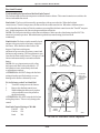
Installing the Pressure Relief and Low-Flow Check Valve
ATTENTION: It is critical that you adhere to the following specifications for pressure relief and
low-flow check valve installation; if these specifications are not met, the metering pump will not
function correctly and the burner will shut down on reset.
The metering pump requires the installation of a pressure relief and low-flow check valve as shown in Figures
4H, 4J, and 4K.
• The pressure relief will open and relieve pressure on the line if there is a restriction in the
pressure oil line, clogged nozzle, etc.
• The low-flow check valve is a vital component which maintains pressure in the oil pressure
line.
Be sure to use Permatex #2 non-hardening gasket sealer to seal every threaded fitting. DO NOT use teflon
tape or teflon pipe dope compounds.
1.
2.
3.
4.
Refer to Figure 4K.
Remove the plug from the gauge port on top of the metering pump head.
Install the pressure relief valve assembly in a vertical position in the gauge port. Note that the
directional arrows on the relief valve must be positioned so that the arrows point away from the
pump head (i.e. in the direction of the oil flow).
Install 1/4" O.D. copper tubing (user-supplied) from the pressure relief back to the oil tank.
Refer to Figure 4J as needed.
PRESSURE RELIEF
VALVE COMPONENTS
Included with metering pump
32062
MALE CONNECTOR
1/4 T TO 1/4 NPT
TO BURNER
32293
RELIEF VALVE
32425
1/4 NPT BRASS TEE
32424
LOW FLOW CHECK VALVE
32335
ADAPTOR PIPE, 1/4 F X 1/8 M
TO TANK
FROM PUMP
Figure 4K - Pressure Relief Valve Assembly Detail
4-16
I88692−A
Operator's Manual: Model CB-1400
Installing the Pressure Oil Line Components
ATTENTION: It is critical that you adhere to the following specifications for pressure oil line
installation (oil line from the pump to the furnace); if these specifications are not met, the metering pump
will not function correctly and the burner will shut down on reset.
1.
2.
3.
•
The parameters for pressure oil line installation are:
Length of Pressure Line
Line Size
Up to 100 feet
3/8" O.D. copper tubing
•
The pressure oil line must slant up to the burner with no loops or high points to trap air.
•
Local codes may require the installation of an in-line "Fire-O-Matic" safety valve.
Be sure to check all appropriate codes to ensure compliance.
Refer to Figures 4H, 4J, and 4K.
Make sure you have purchased all the necessary fittings to complete the installation correctly.
Install the fittings and components as shown in the related illustrations. Be sure to use Permatex #2
non-hardening gasket sealer to seal every threaded fitting. DO NOT use teflon tape or teflon pipe dope
compounds.
Installing the Compressed Air Line
NOTE: Your air compressor system must supply air pressure to the furnace with the following
requirements: 50 psi and water trap or dryer. If you do not have shop air, an optional air compressor is
available. Contact your local Clean Burn dealer for more information.
1.
Run a compressed air line from your shop air to the connector block on the furnace. Use minimum
1/4" O.D. copper tubing or equivalent for for the compressed air line.
2.
Install an easily accessible shut-off valve in the air line so the burner can be serviced without
shutting off the shop air in your service area.
3.
If necessary, install a pressure regulator (additional to the burner air regulator) in the air line, and
set it at 50 psi.
ATTENTION: DO NOT feed full shop air pressure to the burner or damage to burner
components may occur.
4.
Install a water trap or extractor/dryer in the air line with an automatic drain so compressed air
(rather than water) is supplied to the burner.
ATTENTION: Water must not be fed to the burner, or the flame will be extinguished and the
burner will shut down. Be sure to drain water from your compressor tank on a regular basis to
keep water out of the air line.
4-17
Operator's Manual: Model CB-1400
Installing the Stack
WARNING: Inappropriate stack materials or improper stack design/installation can adversely
affect the proper, safe operation of your furnace. Contact your Clean Burn dealer to purchase the
proper stack components for your furnace.
Stack designs are generally classified as follows:
(1) "Class A" stack through the ceiling of the building (refer to Figure 4L)
(2) "Class A" stack through the sidewall and up the side of the building (refer to Figure 4M)
Stack Design and Specifications
ATTENTION: The stack design must be single and dedicated for each unit (furnace) according to
the following specifications. A single stack serving more than one unit MUST be engineered/certified for
that specific installation (ref. NFPA 211, 3.3.39 and 10.2.1; NFPA 31 6.5.16-18). Failure to adhere to this
rule may result in less than optimal system performance.
Figures 4L and 4M illustrate recommended stack designs. Choose the stack design which is appropriate for
your furnace installation and review all specifications provided in the corresponding drawing. When designing
your stack, adhere to the following specifications:
• Model CB-1400 requires minimum 8" I.D. stack components.
• Ensure that the vertical stack height is at least 10 feet PLUS one foot for every fitting (e.g.
45 degree, 90 degree, or T) in the stack run. If needed, increase the vertical length of the stack
or install a draft inducer to obtain -.02" W.C. draft over fire. (Section 8 contains details on
adjusting the draft.)
• Keep the horizontal stack run as short as possible; slant it upward at a minimum of 1/4" per
foot of run.
• Keep the stack design simple. Complicated stacks (with long runs and many turns) reduce
draft and result in poor burner performance. Your stack may include only one 90 degree turn.
All other stack turns must be at 45 degrees or less to ensure optimal draft and burner
performance.
NOTE: If you plan to use an existing masonry chimney, the chimney must be lined and inside the building.
Exterior masonry chimneys chill the stack gases and result in poor draft and poor burner performance.
ATTENTION: If you have an exhaust fan(s) in your shop, it is critical that you have adequate make
up air (source of fresh air to replace the stale air exhausted by the fan). When an exhaust fan is run
without adequate make up air, the resultant vacuum in the building will draw combustion products back into the
burner. This back draft causes poor burner performance and may damage vital burner components. Refer to
Section 8 in this manual for additional information.
Stack components should be installed in the following order:
(1) Inside stack (the stack components from the furnace breach to within 18" of the ceiling, roof,
or sidewall of your building)
(2) Barometric damper
(3) "Class A" stack penetration through the ceiling, roof, or sidewall
(4) "Class A" stack on the exterior of the building
(5) "Class A" stack cap
4-18
Operator's Manual: Model CB-1400
Installing the Stack (continued)
WARNING! MAKE SURE TO INSTALL
THE PROPER ROOF SUPPORT
SYSTEM TO SAFELY SUPPORT THE
STACK
10 FT.
WATERTIGHT
ROOF FLASHING
STACK SIZE: MIN. 8"
1/4" HOLE FOR
SETTING DRAFT.
ADJUST BAROMETRIC
DAMPER FOR −.04 W.C.
DRAFT AT BREECH
−0.02 W.C. DRAFT
OVERFIRE IS
ESSENTIAL FOR
PROPER FURNACE
OPERATION.
SEE SECTION 8
ATTENTION:
BAROMETRIC DAMPER
MUST BE INSTALLED SO
IT IS FACING AWAY FROM
SINGLE WALL STACK
MIN. 24 GAUGE
"CLASS A" KIT FOR
INSTALLING "CLASS A" STACK
THROUGH CEILING
EXHAUST GASES FROM
I88833
Figure 4L - Installation of "Class A" Stack Through Roof/Ceiling
4-19
10 FT. MIN. VERTICAL STACK HEIGHT PLUS 1 FT. FOR
EVERY FITTING TO MAINTAIN PROPER DRAFT OVERFIRE
WARNING! ENSURE PROPER
CLEARANCES BETWEEN STACK
COMPONENTS AND COMBUSTIBLES
PER ALL APPLICABLE CODES.
"CLASS A" STACK COMPONENTS
INSULATED STACK WITH A STAINLESS STEEL LINER
NOTE: THE LAST STACK SECTION SHALL EXTEND AT LEAST
3 FEET ABOVE THE HIGHEST POINT AT WHICH IT COMES IN
CONTACT WITH THE ROOF AND AT LEAST 2 FEET HIGHER
THAN ANY RIDGE, PARAPET, WALL OR ROOF STRUCTURE
WITHIN 10 FEET OF IT.
2 FT.
"CLASS A" STACK CAP − NON−RESTRICTIVE TYPE
TO ALLOW FREE FLOW OF THE STACK GASES
Operator's Manual: Model CB-1400
Installing the Stack (continued)
"CLASS A" STACK CAP − NON−RESTRICTIVE TYPE
TO ALLOW FREE FLOW OF THE STACK GASES
WARNING! MAKE SURE TO INSTALL
THE PROPER WALL SUPPORT SYSTEM
TO SAFELY SUPPORT THE STACK
"CLASS A" STACK
PENETRATION AND
CLEAN−OUT TEE
1/4" HOLE FOR
SETTING DRAFT.
ADJUST BAROMETRIC
DAMPER FOR −.04 W.C.
DRAFT AT BREECH
STACK
SIZE
MIN. 8"
BAROMETRIC DAMPER
−0.02 W.C. DRAFT
OVERFIRE IS
ESSENTIAL FOR
PROPER FURNACE
OPERATION.
SEE SECTION 8
M OR E
L E SS
SINGLE WALL STACK
MIN. 24 GAUGE
I88911
Figure 4M - Installation of "Class A" Stack Through Sidewall
4-20
"CLASS A" STACK COMPONENTS
INSULATED STACK WITH A STAINLESS STEEL LINER
10 FT.
10 FT. MINIMUM VERTICAL STACK HEIGHTPLUS 1 FT.
FOR EVERY FITTING TO MAINTAIN PROPER DRAFT OVERFIRE
NOTE: THE LAST STACK SECTION SHALL EXTEND AT LEAST
3 FEET ABOVE THE HIGHEST POINT AT WHICH IT COMES IN
CONTACT WITH THE ROOF AND AT LEAST 2 FEET HIGHER
THAN ANY RIDGE, PARAPET, WALL OR ROOF STRUCTURE
WITHIN 10 FEET OF IT.
2 FT.
WARNING! ENSURE PROPER
CLEARANCES BETWEEN STACK
COMPONENTS AND COMBUSTIBLES
PER ALL APPLICABLE CODES.
Operator's Manual: Model CB-1400
Installing the Interior Stack
WARNING: Single wall stack components may be used only for those portions of the stack
which are located inside your building and away from any fire/burn hazards.
1.
2.
Install the single wall stack with proper clearances from combustibles. Also ensure that the stack
is located a safe distance from all shop personnel.
Install an elbow at the junction of the horizontal and vertical stack components to allow for easy cleaning
of the stack.
ATTENTION: Avoid additional 90-degree turns in the stack. Each additional 90-degree turn
slows down stack gases, creates back-pressure, and results in repeated burner shutdown and
unnecessary service calls. All other turns in the stack should be at a 45-degree (or smaller) angle.
NOTE: IMPORTANT for Canadian Installations - Local codes may require the installation of
a clean-out tee.
Installing the Barometric Damper
1.
Refer to Figure 4L. Install a single wall tee (min. 24 gauge) after the 90 degree elbow in the straight
vertical stack section within three to five feet of the furnace breach. For horizontal stack runs (as shown
in Figure 4M), install the tee after the first straight section of pipe.
NOTE: The tee is required to support the barometric damper. You must purchase this tee when
you purchase your stack materials (8" single wall tee - CB#70174).
2.
Refer to Figure 4N. Install the barometric damper in the opening of the tee. Use a small spirit level to
make sure that it is properly level.
3.
Install two self-tapping screws as shown in Figure 4N (i.e. one on each side of the barometric damper)
to hold the damper in place. DO NOT install a screw at the bottom of the barometric damper, or the
flapper of the damper will not operate correctly.
NOTE: Specifications for adjusting the barometric damper for proper draft overfire are provided in Section 8
of this manual.
I88539
8" CLEAN BURN BAROMETRIC DAMPER
INSTALLED IN SINGLE WALL TEE
ADJUST THIS WEIGHT TO
OBTAIN PROPER DRAFT
1
1
1
31170
No QTY PART #
Figure 4N - Installation of Barometric Damper
4-21
8" BAROMETRIC DAMPER
DESCRIPTION
Operator's Manual: Model CB-1400
Installing the Stack Safety Switch For Canadian Installations
NOTE: CSA Standards require that all heating equipment must be installed with a stack safety switch. If your
heating equipment is being installed in Canada, follow the instructions listed below.
CAUTION: For your safety and the safe operation of your heating equipment, the stack switch must
be installed by a qualified installer in accordance with the installation instructions provided here. Wiring
must be accomplished in accordance with all applicable codes. Failure to adhere to these safety
recommendations may result in serious personal injury and/or equipment damage.
1.
2.
3.
4.
5.
6.
7.
Follow the instructions in the Operator’s Manual, Section 4 to install a proper stack, including the
barometric damper which must be installed within 40 inches of the breach.
NOTE: The barometric damper must be installed so that it is level and the flapper moves freely.
Ensure that main power to the heating equipment is turned OFF.
Position the stack safety switch over the lip of the barometric damper as shown in Figure 4O.
Drill a 1/8” pilot hole for the mounting screw, and mount the stack safety switch using the mounting
screw supplied with the switch.
NOTE: The mounting screw must not interfere with the free movement of the flapper on the barometric
damper.
Install the wall thermostat according to the instructions provided in the Operator’s Manual, Section 4.
Wire the wall thermostat and stack safety switch in series as shown in Figure 4P. Install the wire so that
it is secured away from any hot surfaces.
When the heating equipment installation is completed, follow the instructions in the Operator’s
Manual, Sections 5 and 6 to prime the pump and start/adjust the burner.
Follow instructions in the Operator’s Manual, Section 8 to check the draft; this is crucial for the
proper, safe operation of the heating equipment.
I88964
Figure 4O - Stack Safety Switch Installed on the Barometric Damper
4-22
Operator's Manual: Model CB-1400
Resetting the Stack Safety Switch
WARNING: BURN HAZARD! To prevent serious personal injury, be sure to allow ample time, at
least 30 minutes, for the stack, barometric damper, and switch to cool down before attempting to
access and service these components. It is crucial to identify the cause of the stack obstruction (e.g. heavy
snowfall) and correct it before resetting the stack safety switch and re-starting the burner. DO NOT operate
the heating equipment with an obstructed stack; failure to correct an obstructed stack may result in fire,
explosion, and/or burn hazards causing serious personal injury or death.
NOTE: In locations where heavy snowfall occurs, it is critical that the stack remain unobstructed by snow.
For safe heating equipment operation, be sure to keep the area surrounding the stack clear of snow.
1.
2.
3.
Before resetting the stack safety switch, check the stack to make sure it is clear of any obstructions.
Remove the cover from the stack safety switch, and push the small button in the middle of the switch.
Pushing the stack safety switch reset button will re-establish the thermostat circuit, and the burner will
start (assuming the wall thermostat is calling for heat).
Understanding the Function of the Stack Safety Switch
The Stack Safety Switch monitors the temperature at the barometric damper on the stack and is designed to
detect the obstruction of the free flow of stack gases from the heating equipment and shut down the burner.
Obstruction of the stack results in the “spillage” of stack gases from the barometric damper, which heats up the
switch. The switch then opens, disconnecting the thermostat circuit to the burner, and the burner shuts off.
Stack Safety Switch Specifications
Switching Voltage
Switch OPEN Temperature
Switch Type
24 volts
180 degrees F
L180, normally closed, manual reset
WALL
THERMOSTAT
F F T T
OIL
PRIMARY
STACK
SAFETY
SWITCH
(MOUNTED ON
BAROMETRIC DAMPER)
I88965
Figure 4P - Stack Safety Switch Wiring Diagram
4-23
Operator's Manual: Model CB-1400
Installing the Stack Penetration
WARNING: When running the stack through your ceiling, roof, or sidewall, you must use
Class A/UL 103 HT double-wall insulated all-fuel stack components with a stainless steel liner.
DO NOT run single-wall stack through your ceiling, roof or sidewall. NEVER locate a stack joint inside walls
or in a joist spacer. Ensure proper clearances from combustibles per all applicable codes.
1.
2.
Refer to Figure 4L/4M as needed.
Follow the installation instructions provided by the stack manufacturer.
Installing the Exterior Stack
ATTENTION: All exterior stack pieces must be Class A/UL103 HT double-wall insulated all-fuel
stack components with a stainless steel liner.
• DO NOT use Class B or BW Vent/double-wall stack components (for gas fired appliances only).
• DO NOT use Type L Vent/double-wall stack components (for approved fuel oil appliances only).
• DO NOT use black stack pipe (for solid fuel burning appliances only).
• DO NOT use single-wall stack for your exterior stack. Single-wall exterior stack chills the stack
gases and results in poor draft and poor burner performance.
1.
2.
3.
Refer to Figure 4L/4M as needed.
Follow the installation instructions provided by the stack manufacturer.
Install water-tight roof flashing around the penetration of the exterior stack.
NOTE: Clean Burn recommends the use of "Dektite" roof flashing (or equivalent) which ensures a
water-tight seal when installed properly. Contact your local Clean Burn dealer for details.
Installing the Stack Cap
NOTE: Proper installation of a "Class A" stack cap ensures the free flow of stack gases which is
essential for optimal burner performance.
1.
2.
Refer to Figure 4L/4M as needed. Your stack cap should be classified as: "Class A" non-restrictive,
all-fuel type.
Install the stack cap according to the manufacturer's instructions.
Installing the Optional Draft Inducer
ATTENTION: The draft inducer, Field brand model DI-2, is optional equipment and may be installed
to ensure proper draft. The Field brand draft inducer has been tested for use on Clean Burn furnaces.
DO NOT use other models or brands of draft inducers.
Understanding the Importance of the Draft Inducer
The draft inducer is designed to aid in the removal of the natural draft created by the appliance to vent the
combustion gases to the outside of the building. As the paddle wheel turns, a negative pressure is maintained
within the stack so that the combustion gases can leave the furnace and travel out of the stack. (See Figure
4Q.) Proper sizing, installation, and adjustment of the draft inducer are critical for optimal draft
inducer operation.
4-24
Operator's Manual: Model CB-1400
Installing the Optional Draft Inducer (continued)
Installing the Draft Inducer
WARNING: Turn OFF the main power to the furnace before proceeding with the installation of
the draft inducer.
ATTENTION: It is very important to install the draft inducer on a vertical section of stack to isolate the
inducer from excessive heat and ash buildup. Never install the draft inducer on a horizontal section of stack
close to the furnace breach where heat and ash will damage the inducer motor.
"CLASS A" STACK
OPTIONAL
DRAFT INDUCER
NOTE: INSTALL DRAFT INDUCER IN LAST
SECTION OF VERTICAL STACK TO POSITION
DRAFT INDUCER AWAY FROM FURNACE
BREECH SO THE MOTOR DOES NOT
OVERHEAT. THIS ALSO REDUCES ASH
ACCUMULATION IN THE DRAFT INDUCER.
DRAFT
ADJUSTMENT
PLATE
DO NOT MOUNT THE DRAFT INDUCER IN THE
HORIZONTAL STACK NEAR THE FURNACE
BREECH.
SINGLE WALL
24 GAUGE INTERIOR STACK
2.
Refer to Figure 4Q. Follow the instructions included with the draft inducer to mount the draft
inducer on the section of single-wall vertical stack.
Position the draft plate all the way out so that it does not reduce the draft produced by the draft
inducer. You will adjust the draft plate later as part of Adjusting the Draft Overfire
(Section 8).
5 FEET − 8 FEET
1.
SERVICEMAN ADJUSTS
BAROMETRIC DAMPER TO
OBTAIN −.02 W. C. DRAFT
OVERFIRE
CHECK FOR −0.02 W.C.
DRAFT OVERFIRE
I88835
Figure 4Q - Installation of the Optional Draft Inducer
4-25
Operator's Manual: Model CB-1400
Installing the Optional Draft Inducer (continued)
Wiring the Draft Inducer for Normal Operation*
*(No exhaust fans in the building. Read pages 8-3 to 8-6 if exhaust fans are present.)
1.
Wire the draft inducer according to the Furnace Wiring Diagram provided in Appendix B at the
back of this manual.
Installing the Wall Thermostat
Installing the Wall Thermostat
1.
2.
3.
4.
5.
6.
Select a location for the thermostat on an interior wall away from any hot or cold drafts.
Remove the top cover from the thermostat by pushing gently on the latch at the top center of the
body. (Hold the thermostat base in one hand, and grasp the body with the other hand; push in
on the latch with your thumb, and pull the cover away from the base.)
ATTENTION: DO NOT use a screwdriver to pry the cover off the base, or damage may occur.
Remove the green paper insert and the black plastic battery isolator from the battery section of the
thermostat.
Refer to the Burner Wiring Diagram in Appendix B at the back of this manual. Run two wire,
18-gauge (minimum) thermostat cable from the terminals on the back of the thermostat base to the T/T
terminals of the primary control on the burner.
ATTENTION: NEVER jump between T/T terminals on the primary control without removing
one of the wires. Failure to remove one of the wires will burn out the heat anticipator on the
thermostat and will cause the thermostat to fail.
Mount the thermostat base 60" to 66" from the floor using the hardware provided.
Reassemble the thermostat body onto the base. (Align the hinges at the bottom of the cover with
the slots at the bottom of the base, and swing the cover up into place.)
Replacing the Wall Thermostat Batteries
1.
2.
3.
Proper battery level is indicated by the room temperature being displayed on the LCD screen.
When the battery level becomes low, a battery icon along with the word "REPLACE" will be displayed
in the lower left corner of the LCD screen. Replace the batteries to ensure proper operation, following
the previous instructions on the thermostat disassembly procedure.
If the batteries are not replaced, the display will slowly become dim and not display any information.
The thermostat will eventually not function. If this happens, replace the batteries immediately.
Inspecting the Furnace Installation
Following completion of all installation activities described in this chapter, the furnace should be
inspected by qualified personnel before firing. This ensures that your installation meets all applicable
national and local codes and allows for any deficiencies to be corrected before furnace startup. Improper
installation may void your warranty.
4-26
Operator's Manual: Model CB-1400
SECTION 5: METERING PUMP PRIMING
Understanding Metering Pump Priming
Preparing your Clean Burn furnace for operation begins with priming the metering pump. The
procedures in this section must be performed in sequence without interruption to properly prime the
pump.
ATTENTION: Please note that in order to use the metering pump with the CB-525-S2 burner (and to
accomplish pump priming), the oil regulator assembly must first be removed from the preheater block
assembly. The following procedure provides the necessary instructions.
Required Tools and Materials
The following tools and materials are required for oil pump priming and should be gathered before
starting any procedures:
•
•
•
•
3/8" open-end wrench
Rags
Two containers (minimum one-gallon)
Medium straight-blade screwdriver
5-1
Operator's Manual: Model CB-1400
Preparing the Burner for Use with the Metering Pump
WARNING: To avoid electrical shock hazards, turn off all power to the furnace, and unplug the
burner before proceeding.
1.
2.
3.
4.
5.
6.
7.
Figure 5A shows an exterior view of the burner components. In this procedure, you will be
removing the oil regulator from the preheater block assembly to prepare the burner for use with
the metering pump.
Remove the self-tapping screw with a 1/4" nut driver and swing open the double-hinged lid to expose
the heater block assembly.
Use a 1/8" Allen wrench to loosen the two locking bolts on the locking bar.
Remove the locking bar.
Refer to Figure 5B. Use a 5/32" Allen wrench to remove the four (4) bolts and washers holding
the surface-mounted oil regulator in place, then carefully remove the oil regulator.
Clean the top of the heater block to remove used oil, etc. DO NOT allow any debris to fall into
the oil passageways which have been exposed by the removal of the oil regulator.
Install the square cap with the o-ring using the four (4) bolts and washers. Tighten the four bolts
firmly in a crisscross pattern to ensure that there are no leaks.
DOUBLE−HINGED LID
AIR REGULATOR
REMOVE
OIL REGULATOR
AIR GAUGE
OIL GAUGE
COMBUSTION
AIR BAND
I88794−B
Figure 5A - Detail of Burner Components
5-2
Operator's Manual: Model CB-1400
SAVE AND USE THESE 4
SCREWS AND WASHERS
TO INSTALL SQUARE CAP
STEP 1
REMOVE
THESE PARTS
SURFACE MOUNTED
OIL REGULATOR
(COMPLETE
REGULATOR)
STEP 2
10
9
8
7
6
5
4
3
2
1
INSTALL
SQUARE CAP
AND "O" RING
I88193
Figure 5B - Detail of Heater Block with Surface-Mounted Oil Regulator
5-3
Operator's Manual: Model CB-1400
Priming the Metering Pump
ATTENTION: The priming process must be done precisely as described in this procedure to ensure
that all air is thoroughly bled from the system. Failure to bleed all air from the system will result in
repeated burner shutdowns on reset.
1.
2.
3.
4.
5.
6.
Refer to Figure 5C.
Remove the 5/8" plug from the side of the pump head, and set it aside.
Remove the 1/2" brass cap from the 1/2" brass nipple. Place a funnel in the opening. Slowly
pour used oil into the funnel until oil comes out of the side of the pump head; this will fill the
oil line, canister filter, and pump head with oil.
ATTENTION: Never run the pump head dry (without oil in the pump head); doing so will severely
damage the pump.
Apply Permatex #2 non-hardening gasket sealer to the threads of the plug (removed from the
pump head). Re-install the plug and tighten.
Apply Permatex #2 non-hardening gasket sealer to the threads of the 1/2" brass nipple. Re-install
the 1/2" brass cap on the brass nipple and tighten.
Open the bleeder on the pump two to three (2-3) full turns, and position a container to catch oil
which will flow from the bleeder during pump priming.
Figure 5C - Priming the Metering Pump
5-4
Operator's Manual: Model CB-1400
Priming the Metering Pump (continued)
7.
Activating the Pump
WARNING: Activating the pump for pump priming involves running the burner by
jumping the "F" terminals of the oil primary control. This procedure (i.e. jumping the "F"
terminals) should be used only for this specific purpose--never for normal operation. This
procedure is accomplished easily by two people: one at the burner and one at the wall thermostat.
ATTENTION: When performing this procedure, never jump from an "F" terminal to a "T" terminal,
or severe damage to the primary control will occur.
a. Refer to Figure 5D, Step 1.
ATTENTION: Ensure that the plastic barrier strip is in place between the "F" and "T" terminals as
shown in Figure 5D before proceeding; failure to do so will result in damage to the primary control.
b. Connect a jumper wire to one "F" terminal on the primary control.
c. Adjust the thermostat above room temperature. The burner should start running.
d. Immediately turn the knob on the air regulator clockwise until the air gauge registers 10 to
12 psi. You will adjust the air pressure further during burner startup and operation.
NOTE: No air pressure will register on the air gauge until the burner starts running.
e. The pump should start running.
f. Refer to Figure 5D, Step 2.
g. Within ten seconds, jump the "F" terminals by connecting the jumper wire to the other "F"
terminal.
NOTE: If the safety reset on the primary control activates and the burner stops running while
performing this procedure, follow the instructions in Section 7 to reset the oil primary control
and restart the burner.
JUMPER WIRE
JUMPER WIRE
PLASTIC BARRIER STRIP
CAD CELL WIRES
RESET BUTTON
THERMOSTAT WIRES
STEP 1
CAD CELL WIRES
RESET BUTTON
THERMOSTAT WIRES
STEP 2
CAD CELL WIRES
RESET BUTTON
THERMOSTAT WIRES
STEP 3
I88791−C
Figure 5D - Jumping the Oil Primary Control
ATTENTION: Never touch a jumper wire from an "F" terminal to a "T" terminal on the oil primary
control. This will severely damage your primary control. Make sure that the plastic barrier strip is
in place between the "F" and "T" terminals as shown in Figure 5D.
5-5
Operator's Manual: Model CB-1400
Priming the Metering Pump (continued)
8.
9.
10.
11.
12.
13.
14.
15.
16.
Run the pump until a solid stream of oil flows from the pump bleeder. This will bleed all air out
of the suction line, oil filter and pump head.
ATTENTION: For the metering pump to operate correctly, it is very important that the system
is entirely full of oil and all air is bled out. The burner will shut down if there is any air in the
system.
Close and tighten the bleeder on the pump.
Remove the jumper wire from the primary control; the burner and pump should stop.
Disconnect the pressure oil line from the burner, and position a container to catch oil which will
flow from the pressure oil line during pump priming.
Reset the primary control; the burner should start running. Within ten seconds, jump the "F"
terminals by connecting the jumper wire to the other "F" terminal. This will start the pump again
and allow the oil line to flush out.
Run the oil pump until the proper flow of oil has been established, and the oil line has been
completely flushed out.
Remove the jumper wire from the primary control; the burner and pump should stop.
Re-connect the oil line to the connector block.
Make sure that the cad cell wires are connected to the "F" terminals as illustrated in Figure 5D,
Step 3. Save the jumper wire for future pump priming.
Vacuum Testing the Oil Pump
Vacuum testing the oil pump is a very accurate way to determine the following:
• The condition of the pump -- the ability of the pump to pull a vacuum and suck oil from the tank.
• The condition of the fittings, gaskets and seals from the ball valve to the pump -- these
components must all be airtight to avoid suction leaks.
The following procedure provides instructions for vacuum testing the pump and canister filter on
systems equipped with a ball valve.
ATTENTION: For the pump to pull and hold vacuum, it is critical that all fittings are airtight. If any of
these fittings are loose, the pump may not pull a vacuum or may lose the vacuum rapidly. It is also
critical that all fittings in the suction line, including fittings on the canister filter, are 100% airtight.
1.
2.
3.
Follow the instructions to prime the pump (previous procedure).
NOTE: The pump will not pull a vacuum if the pump is dry. There must be oil in the gears of
the pump before the pump can pull a vacuum.
With the pump running, open the bleeder two to three full turns, and make sure that oil is flowing
from the bleeder. DO NOT close the bleeder yet.
Refer to Figure 5C. Close the ball valve and observe the vacuum gauge.
NOTE: The ball valve must have a stainless steel ball and should be pressure tested by the
manufacturer to ensure that it does not leak. If the ball valve leaks, the vacuum test will not be
accurate.
5-6
Operator's Manual: Model CB-1400
Vacuum Testing the Oil Pump (continued)
4.
5.
The vacuum should increase within 15 seconds to 15 inches of vacuum. When the vacuum gauge reads
15 inches of vacuum, first close and tighten the bleeder, then turn the pump off.
NOTE: If the pump will not pull at least 15 inches of vacuum, there is a very serious suction leak, or
the pump is damaged.
If there are no suction leaks, the system will hold vacuum.
NOTE: It is acceptable for the vacuum to drop one to five inches within one minute as the seal
in the pump seats. The vacuum should then hold steady for 15 minutes.
ATTENTION: If the vacuum drops more than one to five inches within the first minute, there is one
or more leaks somewhere between the pump and the ball valve. Do the following:
•
•
•
Wipe your finger along the cylinder at the shaft of the pump. If there is oil here, the pump
seal is damaged. Replace the pump.
Disassemble and clean all the fittings from the pump to the ball valve. Properly seal all
fittings with Permatex #2 non-hardening gasket sealer or equivalent. Check the condition of
the o-ring on the canister filter and tighten the four canister filter bolts in a crisscross pattern.
Repeat the procedure to vacuum test the system to ensure that the system is air tight.
5-7
Operator's Manual: Model CB-1400
5-8
Operator's Manual: Model CB-1400
SECTION 6: STARTING AND ADJUSTING THE BURNER
Understanding Burner Startup and Adjustment
Starting and adjusting the burner involves a series of separate procedures which must be accomplished
in sequence without interruption. Review all the procedures before attempting burner startup and
adjustment, paying careful attention to safety information statements.
ATTENTION: Please verify that the oil regulator has been removed from the burner as shown in
Figure 6A. If the oil regulator has not been removed, please refer to Section 5 for the necessary
instructions -- Preparing the Burner for Use with the Metering Pump. The metering pump will
automatically supply the correct flow (GPH) of fuel to the burner.
Preparing the Burner for Startup
1.
2.
3.
4.
5.
Turn the switch on the wall thermostat OFF.
NOTE: If your thermostat does not have an OFF setting, disconnect one thermostat wire so
the burner will not run.
Turn the main power to the furnace ON.
Wait at least 15 minutes until the preheater block is thoroughly warmed up. (Feel the back of the
burner box to make sure the preheater is sufficiently warm. The proving switch on the preheater
block will not allow the
burner to start until the block
AIR REGULATOR
is hot.)
NOTE: The preheater block
will remain warm as long as
power is supplied to the
burner. If the main power
LOCKING NUT
supply is ever turned OFF,
you must wait at least 15
COVER PLATE
minutes until the preheater
block is thoroughly warm
before starting the burner.
Refer to Figure 6A to locate
the air regulator.
Loosen the locking nut on
the air regulator.
Turn the adjustment knob
AIR GAUGE
on the air regulator
OIL GAUGE
counterclockwise until 1/2"
of the threads on the knob
are exposed. DO NOT back
the knob all the way out.
COMBUSTION
AIR BAND
I88583
Figure 6A - Component Detail of the CB-525-S2 Burner
6-1
Operator's Manual: Model CB-1400
Preparing the Burner for Startup (continued)
6.
NOTE: The air gauge will not show any pressure until the burner starts. Before starting the
burner for the first time, it is very important to turn the air regulator completely OFF as
described.
Initial Adjustment of the Combustion Air Band:
WARNING: The combustion air band must be properly adjusted to ensure that the burner
ignites and burns correctly. DO NOT attempt to start the burner with the combustion air band wide
open or completely closed. The burner may not ignite correctly. Failure to heed this warning may result
in a fire or explosion hazard.
• Refer to Figure 6A to locate the combustion air band.
• Rotate the combustion air band to adjust it to the appropriate initial slot opening as listed
in the following Initial Adjustment Chart. Use a ruler to accurately set the slot opening at
the widest section of the slot. This initial setting of the combustion air band will allow you to
start the burner. You will fine tune the combustion air band further as described later in
these instructions.
ATTENTION: The settings shown in the chart below are only initial adjustments. Final adjustments must
be done by inspecting the flame length according to the illustrations provided on the following page.
NOTE: The oil pressure is automatically adjusted by the metering pump. The approximate oil
pressure range during initial startup is 1 to 4 psi for Model CB-1400.
Initial Adjustments for CB-1400
Maximum Input = 140,000 BTUH @ 1.0 GPH with CB525-S2 Burner
Oil Type
#2 Fuel Oil*
Used Crankcase Oil
Used ATF*
Used Hydraulic Oil*
#4 and #5 Fuel Oils
Oil PSI / Flame Length
check flame length
check flame length
check flame length
check flame length
check flame length
Air PSI
Air Band
Nozzle
12-16
12-16
12-16
12-16
12-16
1/4"
1/4"
1/4"
1/4"
1/4"
9-5
9-5
9-5
9-5
9-5
*If you are burning light viscosity oils, it may be necessary to install a smaller nozzle. Call your Clean Burn dealer for
more information.
6-2
Operator's Manual: Model CB-1400
Starting the Burner
1.
2.
Adjust the thermostat setting above room temperature to start the burner.
Adjusting the Air Regulator:
As soon as the burner starts running, turn the knob on the air regulator clockwise to achieve
proper operating air pressure. Refer to the Initial Adjustment Charts.
NOTE: If the safety reset on the primary control is activated and the burner stops running, see
Section 7 for further instructions on restarting your burner.
Observing the Flame Length:
Visually inspect the flame length through the
observation port. Refer to Figure 6B for an illustration
of the desired flame length. The flame should extend
no more than one-half of the way down the combustion
chamber.
WARNING: The observation port gets hot as the
burner fires. To avoid personal injury, always wear
heavy work gloves and safety glasses when opening the port
and viewing the flame.
3.
CAUTION
WHEN OPENING INSPECTION PORT
PORT MAY BE HOT
PROTECT HANDS
WEAR SAFETY GOGGLES
KEEP FACE AWAY
OPEN PORT SLOWLY
Correct Maximum Flame Adjustment
(Proper Oil and Air Pressure with correct supply of
Combustion Air):
• Flame goes half of the way down the
combustion chamber.
• Flame does not touch back or walls of
combustion chamber.
Incorrect Flame Adjustment
(Not Enough Combustion Air):
• Flame must not touch back or walls of
combustion chamber.
• Increase combustion air by opening the
air band on the side of the burner.
Incorrect Flame Adjustment
(Air Pressure Too High):
• Ensure proper air pressure setting.
I88372
Figure 6B - Flame Length Adjustment
4.
5.
Check the flame length after the burner has fired for 15 minutes.
Tighten the locking nut on the air regulator.
6-3
Operator's Manual: Model CB-1400
Starting the Burner (continued)
6.
7.
Fine Tuning the Combustion Air Band:
NOTE: The initial setting of the combustion air band may require additional adjustment.
• Refer to Figure 6A to identify the combustion air band location on the burner.
• Observe the flame. The flame should be yellow-white with sharp tips and no "sparkles."
• If the flame is orange in color or the flame length is too long, the oil you are burning requires
MORE combustion air. OPEN the air band 1/8" to 1/4", and recheck the flame for the proper
characteristics.
• Recheck the flame after five minutes. You should see a yellow-white flame with sharp tips and
no "sparkles", and the flame should extend half the way down the combustion chamber.
Checking for a Smokeless Burn:
Check for a smokeless burn by observing the stack while the burner is running. If you see any
smoke, repeat the previous steps for setting the combustion air band and adjusting the air
regulator. After adjusting the combustion air band, re-check the flame length.
NOTE: Check for a smokeless burn periodically (as you do the flame length). Immediately
readjust the burner if you ever see smoke coming from the stack. Smoke indicates improper air/
fuel adjustment.
NOTE: When using instruments to adjust the burner for a smokeless burn, the following
readings should be achieved:
• Draft over fire should be -.02 inch w.c.
• Adjust for a smoke spot of a trace to 2
• Adjust for a CO2 reading of 8 to 10% or an O2 reading of 7 to 9%
• Cad cell reading below 500 ohms
Checking the Operation of the Fan Motor
NOTE: It is important to verify that the fan motor operates correctly to ensure that the fan limit control is
properly cycling the fan motor as described below. Also refer to Appendix A (A-10) at the back of the manual
for additional information on the fan limit control.
1.
2.
3.
4.
Start the burner and adjust it as described previously in this section.
The fan motor will not start until the burner has been running for 5 to 15 minutes to heat up the
combustion chamber and heat exchanger. At this point, the fan limit control will activate the fan motor.
Once the fan motor has activated, turn the burner off by turning the wall thermostat to OFF.
With the burner off, the fan motor should continue to run for 5 to 10 minutes until the combustion
chamber is cooled down. The fan limit control will then shut off the motor.
WARNING: If the fan motor does not operate as described, immediately shut down your furnace to
avoid potential equipment damage and/or fire hazard. Contact your Clean Burn dealer immediately.
6-4
Operator's Manual: Model CB-1400
SECTION 7: RESETTING THE OIL PRIMARY CONTROL
Understanding the Oil Primary Control
NOTE: The CB-1400 primary controller (CB Part #33400) is a recycle type control, which features
interrupted ignition operation.
The oil primary control will go into safety lockout and shut the burner off when it detects flame-out
during burner operation. The oil primary control will then wait approximately one to two minutes and
attempt to re-ignite the burner (recycle mode). If the burner does not re-ignite, the control will shut the
burner off on safety. The following procedure explains what should be done when this occurs. It is very
important that you follow these instructions precisely when resetting the safety on the primary control
and restarting the burner.
Using the Reset Button
DANGER! DO NOT push the reset button more than once! DO NOT push the reset button if
oil mist is present in the combustion chamber or when the combustion chamber is hot! DO NOT
operate your furnace if excess oil, oil vapor or fumes have accumulated in or near your furnace. As with
any oil burning furnace, improper operation may result in a fire or explosion hazard.
1.
Refer to Figure 7A.
2.
Check the combustion chamber for fuel mist by shining a flashlight through the observation port.
If you see fog (fuel mist) in the chamber, DO NOT push the reset button.
3.
If the combustion chamber is hot, allow the furnace to cool for at least 30 minutes. DO NOT
push the reset button.
4.
When you are sure all mist has been cleared from the chamber and the combustion chamber is
cool, depress the red button on the primary control for a minimum of three (3) seconds, then
release. Reset the control ONCE ONLY.
5.
If the burner will not restart, call your Clean Burn dealer immediately.
PLASTIC BARRIER STIP
CAD CELL WIRES
ATTENTION: Never touch a jumper wire
from an "F" terminal to a "T" terminal on
the oil primary control. This will severely
damage your primary control. Make sure
the plastic barrier strip is in place between
the "F" and "T" terminals as shown in
Figure 7A.
RESET BUTTON
I88787−C
THERMOSTAT WIRES
FIGURE 7A - Oil Primary Control
7-1
Operator's Manual: Model CB-1400
7-2
Operator's Manual: Model CB-1400
SECTION 8: ADJUSTING THE DRAFT OVERFIRE
Understanding the Importance of Draft
Draft in the furnace is created as the hot combustion gases rise up the stack, creating a negative pressure
inside the stack and the furnace. This negative pressure is measured as inches of water column (W.C.)
of draft. A proper draft overfire of -.02 to -.04 w.c. is essential so that all combustion products travel
away from the burner, down the combustion chamber, through the furnace flues and up the stack.
Checking for Correct Draft Overfire
WARNING: Correct draft overfire is
essential for the proper and safe operation
of your furnace.
Your furnace is equipped with an observation/
draft reading port to check draft overfire. A
qualified serviceman with proper equipment
must check/adjust your furnace for proper draft.
Contact your Clean Burn dealer for this service.
1.
2.
Insert the probe of the draft gauge
instrument into the draft reading port in
the observation port as shown in
Figure 8A.
NOTE: Follow the directions with the
draft gauge to use your specific type of
gauge.
Note the draft overfire reading on the draft
gauge.
ATTENTION: The draft reading should
be in the -.02 to -.04 w.c. range. Poor
draft (i.e. -.01 to +.08) results in back
pressure in the furnace and poor burner
performance. Too much draft overfire
(i.e. greater than -.04) sucks the heat from
the furnace and results in abnormally high
stack temperature.
I88257
Figure 8A - Checking for Proper
Draft Overfire
8-1
Operator's Manual: Model CB-1400
Adjusting the Barometric Damper
NOTE: If the draft overfire is not in the -.02 to -.04 w.c. range, it is necessary to adjust the barometric
damper.
1.
2.
3.
4.
5.
Before starting the burner, turn the weight
on the flapper COUNTERCLOCKWISE
until the flapper remains closed. This will
ADJUST THIS WEIGHT
provide maximum draft for the furnace.
TO OBTAIN PROPER
Follow the directions in Section 6 to start
DRAFT OVERFIRE
and adjust the burner.
With the burner running, check the draft
overfire with a draft gauge.
As shown in Figure 8B, adjust the weight
on the flapper to obtain a consistent
-.02 w.c. draft overfire. Turn the weight
COUNTERCLOCKWISE to increase draft
(i.e. draft increases as the flapper closes).
Turn the weight CLOCKWISE to decrease
draft (i.e. draft decreases as the flapper
I88572
opens).
Tighten the locking nut to securely hold
the weight in position.
Figure 8B - Adjustment of Barometric Damper
Solving Draft Overfire Problems
WARNING! If you cannot achieve proper draft overfire, do not operate your furnace!
Contact your Clean Burn dealer for assistance.
ATTENTION: Backdraft must be resolved or your furnace will not operate correctly!
Under backdraft conditions, draft overfire readings will show positive pressure in the combustion
chamber. Backdraft means that oil spray, combustion products, and heat are blown back against the
burner. Backdraft results in oil-fouled retention heads and electrodes. Severe backdraft will force heat
back against the burner and result in heat damage to the cad cell and transformer.
Backdraft is caused by the following conditions:
• Poor draft caused by improper stack design. (See Section 4.)
• Poor draft caused by improper adjustment of the barometric damper. (See Above)
• Incorrect combustion air band setting on the burner. (See Section 6.)
• Furnace flues are plugged with ash. (See Section 9.)
• Clean-out gasket on Clean-out door is out of position (See Section 9).
• Exhaust fans in your building are sucking gases down the stack. (See following pages)
8-2
Operator's Manual: Model CB-1400
Understanding the Effect of Exhaust Fans on Draft
Any type of exhaust fan, paint booth, or exhaust system in a building will create negative pressure in the building
unless there is a source of make-up air (i.e. fresh air which enters the building and replaces the air removed by
the exhaust fans.) Refer to Figure 8C.
If there is insufficient make-up air, the exhaust fan will suck air and combustion gases down the furnace
stack and create backdraft in the furnace. Even if the exhaust fan is on another level of the building or in
another room away from the furnace, the exhaust fan will still create backdraft at the furnace.
Checking Draft Overfire to Determine Severity of Backdraft
The following procedure is an accurate method of determining how much backdraft is created by the
exhaust fans. Once this is determined, you can select the correct method for resolving the backdraft.
Refer to Figure 8C as needed.
1.
2.
3.
4.
Turn off ALL exhaust fans and close ALL doors and windows in the building (any open door or
window will allow make-up air to enter the building and will negate the test).
Start the furnace and adjust the barometric damper so that the draft overfire is -.02 w.c.
Check the draft overfire again. Now have someone start the exhaust fans.
Note how much the draft overfire has changed.
ATTENTION: If the draft overfire changed towards positive, it is mandatory that make-up air
is provided to the building or severe damage to the furnace and burner will occur (voiding the
warranty). If the draft overfire remained constant at -.02 w.c., there is sufficient make-up air
entering the building, and the exhaust fan is not adversely affecting the draft.
8-3
Operator's Manual: Model CB-1400
BACKDRAFT
EXHUST FAN CREATES BACKDRAFT IN STACK
AND SUCKS COMBUSTION GASES DOWN THE
STACK AND BACK INTO THE FURNACE
To arrive at proper
draft measurements
be sure that all fans
within the building
are running while
adjusting the draft
to final levels!
OIL SPRAY AND HEAT IS FORCED
BACK AGAINST THE BURNER AND
RESULTS IN OIL FOULED ELECTRODES
AND RETENTION HEAD.
SEVERE BACKDRAFT WILL HEAT AND
DAMAGE THE CAD CELL AND THE
TRANSFORMER.
PROPER DRAFT
RISING HOT
COMBUSTION
GASES PRODUCE
PROPER DRAFT
I88836
Figure 8C - Proper Draft vs. Backdraft
8-4
Operator's Manual: Model CB-1400
Installing a Make-up Air Louver
Exhaust Fans and Make-up Air Louvers
When exhaust fans are operated in tight buildings, there is little or no source of fresh air to replace the
air removed from the building by the exhaust fan. This results in negative pressure (vacuum) in the
building which creates severe backdraft problems at the furnace.
Properly sized make-up air louvers are designed to allow adequate fresh air to enter the building during
operation of the exhaust fans. The louvers automatically open under the vacuum created by the exhaust
fans. The louvers open just enough to provide the correct CFM of fresh air. The louvers automatically
close when the exhaust fans are turned off.
Sizing the Make-up Air Louver
IMPORTANT NOTE: When using louvers and grills, and the actual free area of the louver or grill is not
known, it is understood that wooden louvers/grills will have a free area of 25%, while metal louvers/grills will
have a free area of 75%. ("Free area" translates into the actual space allowing air to flow through.)
Procedure 1: (a) Determine the CFM rating of the exhaust fan. This information should be stamped on
a label on the exhaust fan. Make sure to add up the total CFM if more than one
exhaust fan exists in the building.
(b) Select the correct size of make-up air louver to provide the required CFM of fresh air.
If you cannot determine the CFM rating of the exhaust fan, use the following procedure.
Procedure 2: (a)
(b)
(c)
(d)
(e)
(f)
Count the total number of exhaust fans in the building.
Close all of the doors and windows in the building except for one overhead garage door.
Start the furnace and allow it to run for 15 minutes to bring it up to temperature.
Set the draft-over-fire for -.02" to -.04" W.C.
Turn ON all of the exhaust fans in the building.
Now close the opened overhead garage door slowly, just until the draft gauge moves down
into a positive (+) draft reading; as soon as it reaches this point, STOP the door at that
position.
(g) Slowly open the door back up, just until the draft reading comes back up to the -.02"
to -.04 W.C.
(h) Measure the size of the door opening, rounding this measurement off to the next largest
even foot.
Example of Calculations for Sizing Make-up Air Louver
Measured door opening: 12 ft. wide x 9 in. high
• Round off to 12 ft. wide x 1 ft. high
• Convert to square feet (in this case it equals 12 ft2)
• Multiply by 1.1 correction factor (12 ft2 x 1.1 = 13.2 ft2)
• Multiply by free area factor (13.2 ft2 x 1.25 = 16.5 ft2)
• Refer to sizing chart (following page) - required grill size would be (1) 54 in2 grill
8-5
Operator's Manual: Model CB-1400
Installing a Make-up Air Louver (continued)
Calculated Opening Size
(Square Feet)
Required Louver / Grill Size
(Inches)
From 0.000 to 0.569
10 x 10
From 0.570 to 0.900
12 x 12
From 0.901 to 1.556
16 x 16
From 1.557 to 2.070
18 x 18
From 2.071 to 2.574
20 x 20
From 2.575 to 3.408
24 x 24
From 3.409 to 5.133
30 x 30
From 5.134 to 7.696
36 x 36
From 7.697 to 9.883
42 x 42
From 9.884 to 13.299
48 x 48
From 13.300 to 16.683
54 x 54
From 13.684 to 21.152
60 x 60
Installing the Make-up Air Louver
All louvers and grills, regardless of the material from which they are made, must be FIXED in the OPEN
position OR be interlocked with the appliance so that they will open automatically during the operation of the
appliance. The interlock must be placed on the driven member.
NOTE: It is very important to follow these instructions carefully to ensure proper performance of the louver.
1.
2.
3.
The louver must not be close to the furnace. The fresh air should travel at least 40 to 50 feet before
reaching the furnace, so the air warms up. The furnace will not heat well if it is receiving cold return air.
The louver must be high in the sidewall of the building so the cold fresh air does not blow across the
floor level and chill the service personnel.
The louver should be installed in the opposite wall from the location of the exhaust fan. This
will quickly vent diesel exhaust from the top of the building and reduce the amount of run time
for the exhaust fan.
8-6
Operator's Manual: Model CB-1400
SECTION 9: MAINTENANCE
Understanding Maintenance
Servicing your Clean Burn furnace in a timely manner is very important to keep your furnace running in peak
condition. Just as an automobile requires periodic maintenance such as oil changes, engine
tune-ups, etc. your Clean Burn furnace also requires regularly scheduled service.
WARNING: Failure to maintain and/or improper servicing by unqualified personnel may
adversely affect the proper, safe operation of your furnace, may reduce the service life of your
furnace, and may void your warranty.
The following chart summarizes all the service intervals which are required to maintain your furnace. Service
instructions/procedures for these activities are included in this chapter.
Maintenance Activity
Periodic Burner Inspection
Cleaning the canister filter
Servicing the metering pump
Cleaning the check valve/screen
Cleaning water/sludge out of tank
Cleaning out ash
Annual burner tune-up
Interval
Monthly
Before vacuum gauge reads 10" HG of vacuum
At least once a year
At least once a year
At least once a year
Approx. 700 hours as indicated on the burner hour meter*
At least once a year
*It is very important to clean ash from the furnace on schedule. Normal use of the furnace requires
clean-out at least twice during the heating season. Heavy, around-the-clock usage requires more
frequent clean-out. For instance, one month of continual running of the furnace is 720 hours (24 hours x 30
days = 720 hours).
NOTE: IMPORTANT! Record all maintenance activities in the Maintenance Record provided in
Appendix C.
9-1
Operator's Manual: Model CB-1400
Periodic Burner Inspection
Following initial start up of the burner, you should inspect the operation of the burner periodically--ideally on a
monthly basis. Doing so ensures that the system is functioning efficiently and safely.
Follow these guidelines for inspecting the operation of the burner:
• Visually inspect the flame length through the observation
CAUTION
port; the flame should extend no more than one-half of
WHEN OPENING INSPECTION PORT
the way down the combustion chamber.
-If the flame is diminishing or displays wide
PORT MAY BE HOT
variations, clean the canister filter and check
PROTECT HANDS
valve/screen (procedures provided in this
WEAR SAFETY GOGGLES
section).
KEEP FACE AWAY
OPEN PORT SLOWLY
-If the flame is firing too strongly (i.e. flame
touches back and/or side walls of the
combustion chamber), check the air pressure setting (see following guideline).
• Check the air pressure by observing the air gauge; proper air pressure settings are provided in
Section 6. DO NOT overfire the burner; doing so on a continual basis will damage the furnace.
• Check the combustion air band setting for the proper opening and clean away any dust/debris as
necessary. Note that the air band should NEVER be set fully open or closed.
• Check the draft over fire reading as specified in Section 8.
AIR REGULATOR
LOCKING NUT
COVER PLATE
AIR GAUGE
OIL GAUGE
COMBUSTION
AIR BAND
I88583
Figure 9A - Component Detail of the CB-525-S2 Burner
9-2
Operator's Manual: Model CB-1400
Cleaning the Canister Filter
ATTENTION: Never operate your furnace with more than 10" HG of vacuum on the suction side of
the pump. High vacuum separates air from the oil and results in erratic burner operation.
The following protective gear should be worn when cleaning the filter:
• Rubber gloves
• Safety goggles
1.
2.
3.
4.
5.
6.
7.
8.
9.
Close the ball valve adjacent to the filter.
Position a container under the filter.
Unscrew the four bolts to drain the oil from the canister.
Remove the canister bowl.
Clean the screen and the bowl in a parts washer.
Referring to Figure 9B, examine the filter components as you reassemble them.
Check the condition of the O-rings. Replace any that are cracked or worn.
Ensure that the canister filter is 100% airtight by firmly tightening the four bolts.
After the pump head screen is serviced as well (page 9-4) open the ball valve and refer to Sections
5 and 6 for instructions on priming the pump and starting the burner.
BACK TO
TANK
TO BURNER
USE A RATCHET WRENCH WITH A 6" EXTENSION
AND 3/16" "ALLEN" SOCKET TO REMOVE THE
FOUR "ALLEN" SCREWS
I88259−A
Figure 9B - Canister Filter Component Detail
9-3
Operator's Manual: Model CB-1400
Servicing the Metering Pump
1.
2.
3.
4.
5.
6.
Refer to Figure 9C.
Remove the pump head cover (part 1).
Remove the screen (part 2) and wash it.
Remove and discard the used gasket (part 3).
Install a new gasket (Clean Burn Part #32422).
Replace the screen and pump head cover.
3
2
1
PART No 32422
PART No 32423
Figure 9C - Servicing the Metering Pump
9-4
Operator's Manual: Model CB-1400
Cleaning the Check Valve And Check Valve Screen
This procedure applies to furnace installations with inside and outside tanks. The following protective
gear should be worn when cleaning the check valve/screen:
• Rubber gloves
• Safety goggles
1.
2.
3.
4.
5.
Refer to Figure 9D. Remove the one-piece suction oil line from the tank.
Remove the check valve and screen. Clean these components in a parts washer.
Check the operation of the check valve. The valve must seat so it is airtight to hold pump prime.
Re-assemble and re-install the components. Apply Permatex #2 non-hardening gasket sealer or
equivalent to the threaded fittings. Firmly tighten all connections so the suction line is 100%
airtight.
Follow pump priming instructions in Section 5 to re-establish prime.
TO BURNER
METERING PUMP
FUNNEL WITH
BALL VALVE
SUCTION
OIL LINE
EMERGENCY
VENT
CLEANOUT
VENT
CAP
OIL STORAGE TANK
CHECK VALVE
CHECK VALVE SCREEN
I88670−D
Figure 9D - Check Valve Detail
9-5
Operator's Manual: Model CB-1400
Cleaning the Tank
DO NOT allow water, sludge, or other debris to accumulate in your oil supply tank to the point that noncombustible or harmful materials are drawn into the pump or burner.
Drain water and sludge from the bottom of your tank at least once a year, and more frequently with water
accumulation.
NOTE: If your used oil tank has not been cleaned on a regular basis, a considerable amount of sludge,
etc. may have accumulated on the bottom of the tank. Under these circumstances, it is advisable for you
to hire your used oil hauler to pump the tank. Make sure the tank is pumped to the bottom to remove all
sludge, etc. from the tank (your used oil hauler may charge an additional fee for this type of service).
The best time to pump the used oil tank is at the end of the heating season when the tank is low. This
allows sufficient time to refill the tank with used oil (generated by your company over the summer
months) so that you have adequate fuel for the heating season.
Cleaning Ash from the Furnace
NOTE: The maintenance interval for cleaning ash from the furnace is approximately 700 hours of
operation as indicated on the hour meter on the burner (refer to the servicing intervals at the beginning of
this chapter). Be sure to clean the ash from your furnace at least twice during the heating season.
Your furnace may require more frequent clean out of the ash due to contaminants in the oil or heavy
use. As ash accumulates, furnace heat output declines, and the stack temperature rises. 1/8" of ash has
the insulating capacity of one inch of fiberglass insulation and reduces heat transfer significantly. Never
allow more than 1/4" of ash to accumulate in the combustion chamber, heat exchanger flues, or
stack.
CAUTION: Be aware that used oils may contain heavy metallic compounds or foreign
materials. When burned, these compounds are deposited within the furnace, necessitating
careful cleaning. The following protective gear should be worn when cleaning the ash:
• Respirator for fine particles (a dust mask is not acceptable)
• Safety goggles
• Rubber gloves
• Protective clothing
CAUTION: Make sure you use a sturdy ladder or scaffolding for safe access to ceiling-hung
furnaces.
NOTE: When cleaning the furnace, static electricity may build up in the shop vac hose. If this occurs, use #12
copper wire wrapped around the hose with the other end connected to the furnace (or other ground source) to
eliminate the static.
9-6
Operator's Manual: Model CB-1400
Cleaning Ash from the Furnace (continued)
Figure 9E - Accessing the Combustion Chamber for Cleaning
1.
2.
3.
Ensure that power has been turned OFF, and all "hot" components have been allowed to cool
sufficiently. Allow at least one hour for the target to cool.
Clean out the burner throat:
a. Disconnect the burner power cable.
b. Remove the lock-down nut and swing the burner open.
c. Clean out the burner throat using a small scraper to remove the residues.
ATTENTION: Keep the burner open (swung out) so that you do not knock or bend burner
components when cleaning out the combustion chamber.
Clean the ash from the stack components:
a. Brush accumulated ash from the stack cap.
b. Lightly tap the stack components to loosen the ash.
c. Allow ash and dust to settle in the clean-out tee or elbow.
d. Vacuum ash from the clean-out tee, or disconnect the stack and vacuum ash from the elbow.
9-7
Operator's Manual: Model CB-1400
Cleaning Ash from the Furnace (continued)
4.
Remove the clean-out door to clean ash from inside the combustion chamber (see Figure 9E):
a. Disconnect the stack from the furnace breach.
b. Remove the clean-out panel from the back of the furnace.
c. Remove the clean-out door to expose the heat exchanger flues and the combustion
chamber.
d. Check the color of the ash--it should be light gray or tan.
ATTENTION: White ash indicates excessive air pressure. Black ash or soot indicates lack of
combustion air. If these conditions exist, call your Clean Burn dealer. DO NOT overfire your
furnace by turning up the compressed air pressure. Overfiring will damage the combustion chamber
and heat exchanger and will void your warranty.
f. Use your shop vac to vacuum ash from the flues.
NOTE: Avoid "packing" the ash in the back of the tubes by first vacuuming the flues before
pushing the flue brush down the flues.
g. Use a flue brush to thoroughly clean the flues.
h. Thoroughly vacuum any remaining ash residue from the flues.
i. Check the flues for rust.
ATTENTION: The presence of rust in the flues indicates that chlorinated materials are
being burned. Burning chlorinated materials will severely damage your heat exchanger and
void your warranty. Contact your Clean Burn dealer for instructions to test your oil for
chlorine contamination before firing your furnace.
j. Inspect the fiberglass rope gasket.
NOTE: Make sure the fiberglass rope gasket is in good condition and the clean-out
door seals tightly. If the door does not seal tightly, replace damaged components.
k. Re-install the furnace components: clean-out door, clean-out panel, and stack.
NOTE: You may need to bleed air from the oil line before starting the burner. See Section 5
for the pertinent instructions.
l. Swing the burner into firing position. Install the lock-down nut and plug in the burner power
cable.
9-8
Operator's Manual: Model CB-1400
Annual Burner Tune-up
Your Clean Burn furnace requires annual periodic maintenance. The burner requires an annual tune-up
--similar to an automotive tune-up--to keep it running in peak condition. The burner tune-up should be
performed by a qualified Clean Burn service technician who has the necessary parts and expertise.
Contact your local Clean Burn dealer to schedule the annual periodic maintenance which is usually
(preferably) performed during warm weather to prepare the furnace for the next heating season. Various
levels of service are provided to fit your particular need.
End of Season Maintenance
ATTENTION: Turn main power to your furnace OFF at the end of the heating season. This will
prevent the oil from being "cooked" in the pre-heater block when it is not in use. Failure to do so may result in
carbon build up in the burner preheater block which will block oil flow.
ATTENTION: EPA regulations allow your used oil to be burned only for "heat recovery." DO NOT operate
your furnace during warm weather just to burn oil, or severe damage to the combustion chamber/heat exchanger
may occur.
Contact your local Clean Burn dealer to schedule your annual burner tune-up. Allow only trained, authorized
service personnel to service your burner.
9-9
Operator's Manual: Model CB-1400
9-10
Operator's Manual: Model CB-1400
SECTION 10: TROUBLESHOOTING
The following charts and tables are provided for reference in troubleshooting any difficulties
encountered in furnace operation and adjustment.
•
The Flow Chart outlines the proper sequence of events in furnace operation -- use this
chart to help diagnose where a problem may be occurring.
•
More specific troubleshooting information is provided in the Troubleshooting Tables
following the flow charts. Each table lists a Problem, Possible Cause, and Possible
Action(s) to fix the problem.
10-1
10-2
Air sensing switch
receives power from
centrifugal switch.
Air sensing switch closes
as it receives more than
10 psi of air pressure.
Fan switch sends power
to motor, and Fan starts.
Fan / Limit Control senses Fan OFF
temperature (100 °F) and Fan switch opens.
FURNACE COOL DOWN SEQUENCE
Fan / Limit Control senses
ON temperature (120 °F)
and Fan switch closes.
FURNACE HEATING SEQUENCE
Centrifugal switch closes and
sends power to the air
sensing switch.
INITIAL START-UP
Combustion air band adjusted
for proper combustion air.
INITIAL START-UP
Air regulator adjusted to
proper psi of air pressure.
BURNER IGNITION SEQUENCE
Fan stops running.
Warm air delivered
to heated area.
Hour meter starts.
Yellow indicator
light ON.
Pump circuit starts
oil pump.
Pump circuit opens
oil solenoid.
F120 proving switch remains closed and oil
primary control has power.
NORMAL BURNER OPERATION
Preheater thermostat cycles 400 watt block
heater element and maintains 140 °F block
temperature.
When block temperature reaches 120 °F , the
F120 proving switch closes and sends power
to the oil primary control.
INITIAL START-UP
BURNER PRE-IGNITION SEQUENCE
Preheater thermostat activates 400 watt block
heater element and heats the block to 140 °F.
Fan continues to run to drive
latent heat from the heat exchanger.
Fan / Limit Control
senses temperature
rise as the burner fires.
Burner motor starts and
reaches full rpm.
Air solenoid
opens.
14,000 volt igniter starts,
providing continuous
spark at electrode gap.
Green indicator
light ON.
Burner cable
plugged in.
Main power ON
sending power to
centrifugal switch
and high limit switch.
Primary control relay
opens and the burner
shuts off.
FLOW CHART
CB-1400
115 V / 60 Hz
I88838
Wall thermostat is
satisfied and T
circuit opens.
Burner continues to run
until the wall thermostat
is satisfied.
Oil primary control
receives <500 ohm signal
from cad cell indicating
proper ignition.
Burner ignites.
Burner ignition sequence begins.
Oil primary control relay closes.
Oil primary control checks for
2000+ ohms from cad cell
indicating dark in the combustion
chamber (NO FLAME)
Wall thermostat calls for heat and
closes 24V thermostat.
Operator's Manual: Model CB-1400
Operator's Manual: Model CB-1400
Troubleshooting Tables
PROBLEM
Burner won’t run at all and
Green power light is NOT ON.
Burner won’t run at all and
Green power light is ON.
POSSIBLE CAUSE
POSSIBLE ACTION(S)
1.
2.
Circuit breaker/main switch open.
Fuse/breaker blown.
1.
2.
3.
3.
2.
Burner cable is damaged or not
plugged in properly.
Oil primary control has shut down
on safety reset.
Wall thermostat is not operating.
3.
Heater block is not heating up.
3.
4.
F-120 proving switch has not
closed.
4.
5.
Oil primary control terminals are
not wired correctly.
5.
6.
Oil primary control is damaged.
6.
7.
The High Limit Switch on the
Fan / Limit Control has activated.
7.
1.
10-3
1.
2.
Close circuit breaker/switch.
Electrician should check out
electrical system.
Check burner cable.
Follow the directions in Section 7
to reset the oil primary control.
Check the wall thermostat and
thermostat cable.
Feel the back of the burner; it
should be 140 degrees F. If the
heater block is NOT HOT: (a)
Wait 15 minutes for the heater
block to heat up and re-check the
back of the burner, and (b) Check
the block heater thermostat and
block heater element. Refer to
the wiring diagram and ladder
schematic in Appendix B.
If the block is HOT: (a) Check the
red wire at the F-120 proving
switch for power. If there is NO
power at the red wire, refer to the
wiring diagram and ladder
schematic in Appendix B to
troubleshoot the circuit that
provides power to the proving
switch. (b) If there is power at the
red wire at the proving switch,
check for power at the black wire.
If there is NO power at the black
wire, replace the F-120 proving
switch.
Check the oil primary control: (a)
Check that the “F” terminals are
NOT jumped. (b) Check that the
two yellow cad cell wires are
connected to the “F” terminals. (c)
Check that the two thermostat
wires are connected to the “T”
terminals.
Replace oil primary control: (a)
Check voltage – it must be 115
volts.
Refer to Appendix A for
instructions on the Fan / Limit
Control.
Operator's Manual: Model CB-1400
Troubleshooting Tables (continued)
PROBLEM
Burner ignites, but will not stay running
and Burner shuts off on reset within 15
seconds.
Burner ignites and runs properly, but the
burner shuts off on reset periodically
(e.g. the burner goes off on reset during
the night and requires resetting in the
morning).
POSSIBLE CAUSE
POSSIBLE ACTION(S)
1.
There is a fuel delivery problem.
1.
2.
The cad cell is dirty.
2.
3.
Cad cell wires are loose.
3.
4.
Cad cell / cad cell wires are
damaged.
4.
5.
The primary control is not
receiving the proper ohm signal
from the cad cell.
5.
1.
There is air in the suction oil line
due to leaks at the fittings
1.
There is air trapped in a high point
in the pressure oil line.
2.
.
2.
10-4
Follow the procedures listed in the
next problem.
Clean and check the condition of
the cad cell and cad cell wires.
Check that the yellow wires are
connected properly at the “F”
terminals on the oil primary
control.
Replace the cad cell and cad cell
wires. If the cad cell is heat
damaged: (a) Clean your
furnace, including the combustion
chamber, flues and stack. Refer
to instructions in Section 9. (b)
Check for backdraft caused by
exhaust fans in your building.
Follow instructions in Section 8.
Disconnect the yellow wires from
the “F” terminals. Start the burner
and check the ohm reading from
the cad cell. You have 10
seconds to perform this test
before the burner shuts off on
reset. Refer to Section 7 to reset
the oil primary control. If the ohm
reading is above 500 ohms: (a)
Check the position of the cad cell;
the cad cell must “look” straight
through the central hole in the
retention head. (b) Check the
position of the retention head
according to Appendix A.
Follow the procedures in Section
5 to vacuum test the pump. Reinstall and properly seal the
suction line fittings to eliminate air
leaks.
Follow instructions in Section 4 to
bleed the air out of the pressure
oil line.
Operator's Manual: Model CB-1400
Troubleshooting Tables (continued)
PROBLEM
Burner ignites and Burner shuts off on
reset sometime later during the day or
night.
POSSIBLE CAUSE
POSSIBLE ACTION(S)
1.
There is air in the fuel supply.
1.
2.
2.
3.
The primary control is not
receiving the proper ohm signal
from the cad cell.
There is insufficient air pressure.
4.
The heater block is cold.
4.
5.
The electrodes are fouled.
5.
10-5
3.
Prime the pump. If the pump will
not prime or there is air in the oil
stream from the pump bleeder,
follow the steps in the next
problem (“Pump will not prime.”)
Check for proper ohm signal.
Follow the procedures in the
previous problem (top, page 10-4)
Follow the instructions in Section
5 to adjust the air regulator for
proper air pressure. DO NOT turn
the air compressor off while the
furnace is operating. If you turn
the air compressor off at night,
turn the wall thermostat to OFF so
the burner will not run.
DO NOT shut off power to the
furnace overnight, or the heater
block will cool down, and the
burner will not re-start the next
morning. To turn the furnace “off”
overnight, turn the wall thermostat
to OFF. The heater block will stay
hot.
If oil residues have built up on the
electrodes and retention head,
follow the instructions in Section 8
to check for proper draft overfire.
Clean the electrodes and
retention head.
Operator's Manual: Model CB-1400
Troubleshooting Tables (continued)
PROBLEM
Pump will not prime and Pump motor is
running.
POSSIBLE CAUSE
POSSIBLE ACTION(S)
1.
There is a leak(s) in the suction
line.
1.
2.
2.
3.
The pump is not installed so it will
fill with oil during the priming
process.
The pump gears are dry.
4.
The pump seal is damaged.
4.
5.
The ball valve is closed.
5.
6.
The canister filter is dirty.
6.
7.
The check valve is dirty.
7.
8.
The pump is damaged or worn
out.
8.
10-6
3.
Follow the specifications in
Section 4 to make sure the
suction line is installed properly
and that all fittings are 100%
airtight.
Make sure the pump head is filled
with oil prior to starting the pump.
See Section 5.
Follow the procedure in Section 5
to fill the oil line and prime the
pump.
With the pump not running, wipe
your finger along the bottom of
the cylinder at the pump shaft. If
there is oil at the pump shaft, the
seal is damaged. Replace the
pump, or replace the seal.
NOTE: Some oils will expand as
they warm up. Because there is a
check valve in the suction line, the
expanding oil may build up
pressure and damage the oil seal.
Install a mini-accumulator in the
1/8” port of the canister filter to
prevent the pressure build-up.
Open the ball valve on the suction
line.
Refer to Section 9 to clean the
canister filter.
Refer to Section 9 to clean the
check valve.
Replace the pump.
Operator's Manual: Model CB-1400
Troubleshooting Tables (continued)
PROBLEM
POSSIBLE CAUSE
POSSIBLE ACTION(S)
1.
There is NO power on the
pump circuit from the burner.
1.
2.
The pump motor has shut off
on thermal overload.
2.
Fan motor runs all the time.
1.
Fan motor circuit is wired
incorrectly.
1.
Fan motor will not run.
1.
The fan motor is not wired
correctly.
1.
2.
The Fan / Limit switch is
defective.
The fan motor has overheated
and shut down on thermal
reset.
2.
3.
Pump will not prime and Pump motor is
NOT running.
3.
10-7
Start the burner and adjust the air
pressure regulator to 15 PSI. (a) If
the amber “pump” light on the burner
comes ON, the pump circuit on the
burner has activated properly. Refer
to the wiring diagram and ladder
schematic in Appendix B to
troubleshoot the pump circuit from the
burner to the pump. (b) If the amber
“pump” light on the burner does NOT
come ON, there is a problem with
pump circuit in the burner. With the
burner running, check for power at the
brown wire on the air pressure switch.
If there is NO power at the brown
wire, replace the burner motor. If
there is power at the brown wire,
replace the air sensing switch.
(a) The pump motor is too hot—the
internal thermal protection switch shut
the motor off. Wait for the motor to
cool down; the thermal switch will
automatically reset. Check voltage
and amperage draw of the pump
motor. Call your dealer if the problem
persists. (b) The coupling is not
adjusted properly, keeping the shafts
of the motor and pump from turning
freely. Re-position the coupling so
that both shafts turn freely. (c) The
shaft on the motor or oil pump will not
turn freely. If you can’t turn the
shafts, replace the faulty part(s).
Refer to wiring diagram and ladder
schematic in Appendix B to
troubleshoot the fan circuit.
Check the fan motor wiring. Refer to
the wiring diagram and ladder
schematic in Appendix B. Follow the
directions in Section 6 to test for
proper fan operation. If the fan does
not operate, shut OFF power to the
furnace and call your Clean Burn
dealer for service.
Replace the Fan / Limit switch.
The fan motor is too hot – the internal
thermal protection switch shut the
motor off. Wait for the motor to cool
down; the thermal switch will
automatically reset. Check voltage
and amperage draw of the fan motor.
Call your dealer if the problem
persists.
Operator's Manual: Model CB-1400
10-8
Operator's Manual: Model CB-1400
APPENDIX A
Detailed Furnace Specifications
Furnace Technical Specifications
SPECIFICATIONS
CB-1400
BTUH Input
Listed Fuels
140,000 @ 1.0 GPH
#2, #4 Fuel Oils
Used Crankcase Oil
Used ATF
Used Hydraulic Oil
33 ¾ x 29 ¾ x 29
Cabinet Dimensions
(L x W x H, inches)
Furnace Dimensions with Fan
& Burner
(L x W x H, inches)
Approximate Weight (lbs.)
Mounting
Electrical Requirements
Circuit Breaker for Unit Heater
Circuit Breaker for Furnace
with Optional Accessories
Wall Thermostat
Oil Pump
Pump Motor
Pump Motor Rotation
Canister Filter
Stack Size
Fan Motor HP
Fan Blade / Pitch
Fan Limit Control
Fan Limit Settings
47 ¾ x 40 ¾ x 29
320
Ceiling Hung
Bench Tank Kit
Non-combustible Platform
110/120 Volts, 60 Hz
20 Amps
Refer to specifications included with
optional accessories
24 Volt
Suntec A2RA-7710 (CB# 32327)
Bison gear motor (CB# 33291)
CCW shaft end
Lenz DH 750-100
8”
1/3
Three Blade / 21°
Honeywell L4064B
8” Probe
Hi-Limit – 200
Fan ON – 120
Fan OFF – 100
A-1
Operator's Manual: Model CB-1400
Burner Technical Specifications
Burner
CB-525-S2
Ignition Transformer
Carlin Transformer
14,000 Volts
Nozzle
Delavan 9-5
Burner Motor
1/10 HP 3200 RPM
with centrifugal switch
Burner Motor Rotation
CCW shaft end
Compressed Air Requirements
2.0 CFM @ 50 PSI
Oil Primary Control
Carlin Oil Primary
Heater Element in Preheater Block
400 Watts
Air Pressure Switch
MPL 808
Setting for Preheater Thermostat
140 oF
A-2
Operator's Manual: Model CB-1400
Furnace Dimensions
16 7/8"
33 3/4"
20 7/8"
47 3/4"
TOP VIEW (SHOWING MOUNTING LUGS)
WITH BURNER INSTALLED
29 3/4"
23 1/8"
6 7/8"
29"
16 1/4"
SIDE VIEW (LOUVER SIDE)
FRONT VIEW (BURNER SIDE)
40"
WITH FAN INSTALLED
33 3/4"
21 1/4" DIA.
29"
BACK VIEW (FURNACE BREECH SIDE)
SIDE VIEW (FAN SIDE)
I88839
A-3
Operator's Manual: Model CB-1400
Burner Components (CB-525-S2)
25
5
3
23
27
24
SEE ILLUSTRATION
I88543 FOR PART
NUMBERS
6
22
1
26
4
2
21
1
2
4
5
6
7
8
9
10
11
12
13
7
20
8
5
4
6
7
8
3
9
2
19
10
11
1
0
12
13
psi
14
15
9
20
30
40
10
0
50
psi
60
10
11
13
14
18
12
15
16
BURNER CB − 525 − S2
17
I88234−B
Figure A1 - CB-525-S2 Burner Component Detail
A-4
Operator's Manual: Model CB-1400
Burner Components (CB-525-S2) (continued)
Item#
1
2
3
4
5
6
7
8
9
10
11
12
13
14
15
16
17
18
19
20
21
22
23
24
25
26
27
Clean Burn Part#
26103
11359
33188
33335
33189
33116
11243
32178
32235
32179
32253
33297
33169
33168
31113
26044
33175
26053
11335
13148
11265
SEE NOTE ON DRAWING
11334
33149
33150
26052
11308
Qty.
Component Description
1
1
1
1
1
1
1
1
1
1
1
1
1
1
1
1
1
1
1
1
1
AIR INTAKE OUTER PLATE
AIR INTAKE INNER PLATE
CARLIN PRIMARY CONTROL
ISOLATOR
CARLIN IGNITER (TRANSFORMER)
CAD CELL
TRANSFORMER PLATE
OIL GAUGE 0-15 PSI
FEMALE ELBOW (3/16 T x 1/8 NPT)
AIR GAUGE 0-60 PSI
FEMALE ELBOW (1/8 TP x 1/8 NPT)
HOUR METER (60 Hz)
GREEN LIGHT (POWER)
AMBER LIGHT (PUMP)
FAN SQUIRREL CAGE
MOTOR MOUNT PLATE
BLOWER MOTOR
RIGHT SIDE COVER
HOUSING (INCLUDES ITEM 23)
HEATER BLOCK ASSEMBLY
COVER-HINGED
NOZZLE ADAPTER ASSEMBLY
HINGE MOUNTING PLATE
CONNECTOR RECEPTACLE
CONNECTOR PLUG
LATCH BRACKET
RETENTION HEAD
1
1
1
1
1
A-5
Operator's Manual: Model CB-1400
Burner Components (continued)
58
30
(8)
57
31
56
32
(8)
55
60
54
1
3
53
4
2
33
34
59
35
52
36
51
9
50
5
11
37
39
40
47
26
(2)
12
6
(4) 17
29
38
48
(2)
10
29
49
8
7
27
45
41
25
28
42
46
43
44
15
14
1
2
3
4
5
6
7
13
24
8
9
10
11
12
13
16
19
17
18
21 (2)
23
20
22
Figure A2 - Preheater Block Assembly Component Detail
A-6
I88543
Operator's Manual: Model CB-1400
Burner Components (continued)
Item#
C.B. Part#
1
2
3
4
5
6
7
8
9
10
11
12
13
14
15
16
17
18
19
20
21
22
23
24
25
26
27
28
29
30
31
32
33
34
35
36
37
38
39
40
41
42
43
44
45
46
47
48
49
50
51
52
53
54
55
56
57
58
59
60
34169
33183
34165
32000
13150
32007
33298
33381
33418
32199
32050
32189
32043
54020
32201
33247
34036
26059
33057
26090
32190
32202
32201
33173
33041
32325
54020
33011
32359
14090
34148
34114
34147
34022
32306
32226
32364
32227
32360
32361
32223
32222
32221
32362
13142
32308
32309
33311
33312
33313
33314
33315
33316
33317
33318
33319
33320
33321
32322
26107
Qty.
1
1
1
1
1
1
1
1
1
1
2
2
1
1
2
1
4
1
1
1
2
1
1
1
1
1
1
1
2
1
8
8
2
2
2
2
2
2
2
2
2
2
2
2
2
2
2
2
2
2
2
2
2
2
2
2
2
2
2
1
Component Description
ELECTRODE SCREW - 10-32 x 3/4
SINGLE PIECE ELECTRODE
WASHER
9 - 5 NOZZLE
NOZZLE ADAPTOR
PLUG - 1/8 NPT
140 WATTS HEATER
INSULATED CAP CRIMP CONNECTOR
THERMOSTAT L-130
PLUG - 1/16 NPT
SWIVEL FITTING
HEX NIPPLE - 1/8 NPT x 1-1/2
MALE CONNECTOR - 3/16T x 1/8 NPT
3/16 COPPER TUBING(OIL GAUGE LINE)
MACH. SCREW PHILLIPS HD. 6-32 x 3/8 Z
TERMINAL BLOCK
MACH. SCREW PHILLIPS HD. 6-32 x 1/4 Z
TERMINAL BLOCK BRACKET
AIR PRESSURE SWITCH
HEATER BLOCK
HEX NIPPLE - 1/8 NPT x 2
FEMALE ELBOW (FOR 1/4" AIR LINE)
FEMALE ELBOW (FOR 3/8" OIL LINE)
PRE-HEATER ELEMENT (400 WATTS)
PROVING SWITCH (NORMALLY OPEN)
MALE ELBOW 1/8 x 1/8 NPT (FOR AIR GAUGE LINE)
3/16 COPPER TUBING(OIL GAUGE LINE)
HEATER BLOCK THERMOSTAT(NORMALLY CLOSED)
REGULATOR SURFACE MOUNT
REGULATOR LOCK PLATE
REGULATOR MOUNTING SCREW
LOCK WASHER #8 Z
REGULATOR THREADED STEM
HEX NU T - 10-32 Z
BONNET
DIAPHRAM RING
CAP AND BALL ASSEMBLY
COMPRESSION SPRING
DIAPHRAM
BRASS POPPET SEAT
POPPET ‘O” RING
POPPET VALVE
POPPET SPRING
BASE
REGULATOR KIT COMPONENTS
REGULATOR OUTER “O” RING
REGULATOR INNER “O” RING
SOLENOID INNER “O” RING
SOLENOID OUTER “O” RING
MANIFOLD MOUNT SOLENOID BODY
BODY “O” RING
PLUNGER ASSEMBLY
PLUNGER GUIDE ASSEMBLY
FLUX PLATE
WASHER SEAL
COIL
COIL HOUSING
NUT
AIR/OIL SOLENOID ASSEMBLY
REG. SQUARE CAP
A-7
Operator's Manual: Model CB-1400
Burner Components (continued)
INSTALLATION OF THE SPINNER RETENTION HEAD
THE SPINNER RETENTION HEAD FITS INSIDE THE BURNER TUBE AND
REQUIRES (3) SELF−TAPPING SCREWS. IT IS VERY IMPORTANT THAT
THE SPINNER HEAD IS NOT TIPPED FROM SIDE TO SIDE OR FROM
TOP TO BOTTOM.
3X
VIE
W
VIE
W
A
A−
B−
B
USE PROVIDED SCREWDRIVER AS
WEDGE TO HOLD THE SPINNER
RETENTION HEAD IN POSITION. THEN
TIGHTEN THE THREE SCREWS TO
LOCK THE HEAD IN POSITION.
3/16" GAP
BETWEEN
ELECTRODES &
NOZZLE
CRITICAL DIMENSION:
NOZZLE MUST BE 1/8"
AHEAD OF THE DISK.
NOZZLE MUST NOT BE
BEHIND THE DISK.
1/8" SPARK
GAP
SIDE VIEW A−A
SIDE VIEW B−B
I88377
Figure A3 - Burner Electrode Specifications with Spinner Retention Head
A-8
Operator's Manual: Model CB-1400
Burner Components (continued)
Model
CB-1400
Nozzle Size
Delavan 9-5
DISTRIBUTOR
HEAD
NOZZLE SIZE IS
STAMPED ON
FLAT OF
NOZZLE HEAD
ORIFICE
STEM
O−RING
I88678
Removing the Nozzle for Cleaning:
NOTE: Due to swivel fittings on the air and oil lines, it is not necessary to disconnect these lines
when swinging the burner open.
1.
Remove the lock-down nut on the mounting flange bolt.
2.
Disconnect the burner power cable.
3.
Carefully swing the burner open to its maintenance position.
4.
Remove the nozzle from the nozzle adapter with a 5/8" socket.
Cleaning the Nozzle:
1.
2.
3.
4.
5.
6.
7.
8.
Unscrew the stem from the nozzle head.
Spray WD-40 or equivalent through the orifice to thoroughly remove any blockage.
CAUTION: DO NOT damage or deform the nozzle orifice; DO NOT use a torch tip
cleaner or other inappropriate device to clean the orifice. If the blockage is a "tarry"
material or a hard, black material, call your Clean Burn dealer for service.
Flush all components with WD-40 to remove oil residues.
Reassemble the nozzle components. When tightening the stem, just barely "snug" it down.
DO NOT overtighten.
Check the O-ring on the nozzle stem. Replace the O-ring if it is in the least bit cut or
deformed.
Lubricate the O-ring on the nozzle stem with a couple of drops of new motor oil, then reinstall the nozzle.
Check the electrodes for proper gap and clearances. (Figure A3)
Re-install the burner and adjust for optimal performance as described in Section 6.
NOTE: If the nozzle plugs within a few days after cleaning, call your Clean Burn Dealer for
service.
Figure A4 - Cleaning the Nozzle
A-9
Operator's Manual: Model CB-1400
Fan Limit Control
Understanding the Operation of the Fan Limit Control
The fan limit control senses air temperature within the furnace cabinet. This control contains two switches: the
limit switch and the fan switch.
Fan Switch: The fan switch is normally open and provides power to the fan. When the fan limit
control senses "Fan On" temperature, the fan switch closes and starts the fan. When the wall thermostat is
satisfied and the burner shuts off, the fan continues to run until the fan limit control senses the "Fan Off" temperature. At this temperature, the fan switch opens and shuts off the fan.
NOTE: The fan limit control has a white fan switch button. Make sure the white button is pulled OUT for
automatic (normal) operation. When the button is pushed in (manual setting), the fan will run
continuously.
Fan Limit Control Settings: CB-1400
Fan Off: 100
Fan On: 120
Limit:
200
50
250
100
200
150
FAN OFF
(LEFT POINTER)
FAN ON
(MIDDLE POINTER)
LIMIT
(RIGHT POINTER)
TO RELEASE
WIRE, PUSH
SCREWDRIVER
IN AND PULL
WIRE OUT
CAUTION
DO NOT ROTATE
HOLD DIAL WHEN SETTING
POINTERS
50
250
100
200
150
LOAD
LOAD
LIMIT
FAN
LINE
LINE
BRASS
JUMPER
BLACK WIRE
RED WIRE (CONNECT TO LIMIT)
To Set Pointers on the Fan Limit Dial
1.
Turn OFF main power to the furnace.
2.
Remove the fan limit control cover.
3.
While holding the dial securely in place
with your thumb, move the pointer to
the desired setting.
ATTENTION: DO NOT rotate the dial when
setting the pointers. This severely damages the
control.
CAUTION
DO NOT ROTATE
HOLD DIAL WHEN SETTING
POINTERS
ORANGE WIRE (CONNECT TO FAN)
Limit Switch: The limit switch is normally closed
and provides power to the oil primary control on
the burner. If the fan limit control senses 200
degrees F, the limit switch opens
and shuts off power to the oil primary control and
the burner stops running. The fan continues to run.
Once the fan limit control senses 170 degrees F, the
limit switch automatically resets and restarts the
burner.
NOTE: It is very important to avoid cycling
the burner on hi limit as described above. If
the hi limit activates, immediately check and
re-adjust burner settings.
ATTENTION: DO NOT change the fan limit
settings from the specified settings, or severe
damage to the furnace cabinet may occur.
I88840
FIGURE A5 - Fan Limit Control Components
A-10
Operator's Manual: Model CB-1400
APPENDIX B
Wiring Diagrams
120 VOLTS, 60 Hz, SINGLE PHASE
BLACK
BLACK
WHITE
L1
L1
L1
L2
WHITE
L2
L2
CIRC. FAN
MOTOR
BLACK
3
WHITE
4
OIL PUMP
BLACK
BLACK
WHITE
DRAFT INDUCER
FAN (OPTIONAL)
PURPLE
ORANGE
WHITE
RED
GREEN
GROUND
SCREW
ORANGE
GREEN
FAN LIMIT SWITCH
(COVER REMOVED)
WHITE
WHITE
BLACK
GREEN
RED
BLACK
RED
I88546
FIGURE B1 - Furnace Wiring Diagram
B-1
FIGURE B2 - Burner Wiring Diagram
140 WATTS NOZZLE HEATER
WALL
THERMO−
STAT
NOZZLE
TEMP.SW.
RED
BLACK
BLACK
RED
AIR
SOLENOID
OIL
SOLENOID
CAD CELL
YELLOW
PRIMARY
OIL
FORMER
TRANS−
BLACK
140
BLUE
ORANGE
WHITE
F F T T
MOTOR
BURNER
WHITE
JUMPERS
WHITE
1 2 3 4 5 6
9 10 11 12 13
I88249−B
CAPACITOR
BROWN
BROWN
7 8
GREEN
GREEN
LIGHT
CENTRIFUGAL
SWITCH
B-2
YELLOW
BLACK
AMBER
LIGHT
PREHEATER THERMOSTAT
BLACK
BROWN
METER
HOUR
BLUE
WHITE
AIR
SWITCH
N.O.
(OPTIONAL)
COMPRESSOR
AIR
BLOCK HEATER 400 WATTS
TO RELEASE OR INSTALL A WIRE, CAREFULLY PUSH THE
BLADE OF THE SCREWDRIVER INTO THE RELEASE SLOT
ON THE TERMINAL STRIP UNTIL YOU FEEL THE JAWS "SNAP"
WIDE OPEN. LEAVE THE BLADE IN THE RELEASE SLOT TO
REMOVE OR INSTALL A WIRE. TO RELEASE THE JAWS,
CAREFULLY PULL THE BLADE OF THE SCREWDRIVER
FROM THE RELEASE SLOT.
NOTE: WHEN RELEASING OR INSTALLING WIRES ON THE
TERMINAL STRIP USE THE SMALL SCREWDRIVER SUPPLIED
WITH THE BURNER TO RELEASE THE TERMINAL JAWS.
TO LOCATE THE SCREWDRIVER, OPEN THE HINGED ACCESS
PLATE ON THE TOP OF THE BURNER. THE SCREWDRIVER
IS CLIPPED TO THE INSIDE OF THE BURNER HOUSING
ON THE RIGHT.
BLACK
BLACK
RED
PROVING SWITCH 120° N.O.
BLACK
CONNECTOR (FACE)
Operator's Manual: Model CB-1400
Wiring Diagrams (continued)
Operator's Manual: Model CB-1400
OPTIONAL SERVICE
HOT
NEUTRAL
CIRC FAN MOTOR
FAN
M1
FAN LIMIT CONTROL
SEE OPERATOR'S
MANUAL
HI LIMIT
OIL PUMP MOTOR
M2
GRN
RD
WHT
BK
DRAFT INDUCER MOTOR
(OPTIONAL)
WHT
GRN
WALL
THERMOSTAT
BK
CAD
CELL
PROVING SWITCH
120°
RD
BK
F
U
R
N
A
C
E
F
OR
F
T
OIL
PRIMARY
CONTROL
T
WHT
AIR COMPRESSOR (OPTIONAL)
AIR SOL.
IGNITION TRANSF.
B
U
R
N
E
R
SPARK GAP
BURNER MOTOR
M3
OIL SOL.
AIR PRESSURE
PUMP ON
A
CENTRIFUGAL SWITCH
N. C. HELD OPEN
ACTUATED BY BURNER MOTOR
HOUR METER
BLOCK THERMOSTAT
140°
400 WATTS BLOCK HEATER
NOZZLE ADAPTOR THERMOSTAT
130°
140 WATTS NOZZLE HEATER
POWER ON
- CONNECTION TO
CUSTOMER POWER
44046
DWG. No.............
B-3
FIGURE B3 - Ladder Schematic for Model CB-1400 (120 Volts / 60 Hz)
DISCONNECT SWITCH
Operator's Manual: Model CB-1400
Wiring Diagrams (continued)
H44040
Figure B4 - Metering Pump Wiring Schematic
B-4
Operator's Manual: Model CB-1400
APPENDIX C
Furnace Service Record
Furnace Purchased:
Date __________
From (name/phone)________________________________
Furnace Installed:
Date ___________
By (name/phone)__________________________________
Furnace Inspected:
Date __________
By (name/phone)__________________________________
Draft Readings
(date / reading)
Service Record
(date / initials of serviceman)
Burner
Canister
Filter
Stack
Chamber
& Flues
Stack
*A.P.M. = Annual Preventative Maintenance of Burner (Burner Tune-up)
C-1
Oil Tank
A.P.M.*
Operator's Manual: Model CB-1400
C-2