1
AMERICAN SPECIALTIES, INC.
441 Saw Mill River Road, Yonkers, NY 10701 (914) 476-9000
Instructions and Parts Manual
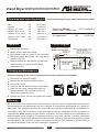
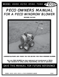
Hand Dryer Operating
Surface-mounted Automatic hand dryer
PLEASE CAREFULLY READ THROUGH THIS MANUAL BEFORE USING THE PRODUCT.
OBSERVING ALL SAFETY INFORMATION, WARNINGS AND CAUTIONS WILL PROTECT
YOURSELF AND OTHERS. PLEASE KEEP INSTRUCTIONS FOR FUTURE REFERENCE.
MODEL # 0141
9-41/64"
(245mm)
MODEL # 0144
6-3/8"
9-7/16"
TECHNICAL SPECIFICATIONS
(162mm)
(240mm)
PERFORMANCE DATA
ITEM CATEGORY
Operating Voltage, 0141
100-120 Vac, 50/60 Hz, 15.8A, 1.9 kW MAX
Operating Voltage, 0144
208-240 Vac, 50/60 Hz, 7.9/9.2A, 2.21 kW MAX
Output Warm Air Volume
142.4 CFM {241.9 m /h}
Output Air Speed
52.5 ft/s {35.8 mi/hr} {16 m/s [57.6 km/hr]}
Output Warm Air Temp
127 F {53 C} at ambient T = 77 F {25 C}
Motor Type
1/8 HP {100W}, 3150 rpm, Brushless Type, Dual Ball Bearings
Motor Thermal Protection
Auto Resetting Thermostat turns unit off at 221 F, {105 C}
Heater Element, 0141
1.7 kW @120Vac, Nichrome 8.5W
Heater Element, 0144
1.7 kW @ 220Vac, Nichrome 28.5 W
Heater Thermal Protection
Auto Resetting Thermostat turns unit off at 189 F, {87 C}, Resets at 122 F {50 C}
Drying Time
Less than 30 seconds
Circuit Operation
Infrared Automatic, self adjusting
Sensor Range
2" to 10" [51 mm to 254 mm], adjustable; standard 7"±25/32" [178 mm ± 20 mm]
Timing Protection
2 minutes auto shut off
Timing Duration
2 seconds delayed turn off after last sensor read
Output Air Nozzle
Sound Level
Heavy-Duty Chrome plated die-cast Zinc, Tilt-Flip type with internal grille
63 ± 3 dB-A
Cover Type
Aluminum, Die Cast, 7/64" (.109"), {2.8mm} thick
Cover Finish
Epoxy Enamel baked-on coating
Net Weight
8.4 lbs [3.8 kg]
Shipping Weight
10.6 lbs [4.8kg]
Unit Size
9-7/16" W x 9-41/64" H x 6-3/8" D [240 mm x 245 mm x 162mm]
INPUT MOD
3
Motor
Heater
Total
VAC
N
Operating A (W)
Vac
Inrush A(W)
Operating A(W)
Inrush A(W)
Operating A(W)
115
0141
115
1.2 (138)
0.80 (92)
115
13.6 (1564)
13.6 (1564)
14.8 (1702)
14.4 (1656)
120
0141
120
1.25 (150)
0.83 (100)
120
14.2 (1704)
14.2 (1704)
15.8 (1896)
15.0 (1800)
208
0144
208
0.64 (133)
0.43 (89)
208
7.3 (1518)
7.3 (1518)
7.9 (1643)
7.7 (1602)
220
0144
220
0.68 (150)
0.45 (100)
220
7.7 (1694)
7.7 (1694)
8.4 (1848)
8.2 (1804)
230
0144
230
0.72 (166)
0.48 (110)
230
8.0 (1840)
8.0 (1840)
8.7 (2001)
8.5 (1955)
240
0144
240
0.75 (180)
0.5 (120)
240
8.4 (2016)
8.4 (2016)
9.2 (2208)
8.9 (2136)
06092857
Vac Inrush A(W)
1
www.americanspecialties.com
Instructions and Parts Manual
Hand Dryer Operating
Surface-mounted Automatic hand dryer
General safety information:
This product is intended
for installation by a qualified service person.
Use AWG NO. 12 solid conductor for wiring.
Disconnect power at the
service breaker before installing or servicing.
Failure to properly ground
unit could result in severe electrical shock
and/or death.
All units must be supplied
with a 3-wire service. The ground wire must
be connected to the dryer's backplate.
-- NOTE: Do not install dryer over washbasin -Installation
1. Make sure power supply breaker is switched off. Installation must be carried out in accordance
with the current edition of the local wiring regulations code having jurisdiction. Installation should
be performed only by a qualified electrician.
2. Place template against wall at desired height (see mounting height recommendations) and mark
locations of 4 mounting holes and wire service entry at knockout (KO) location.
Note: For two or more dryers, dryers should be no closer than 24 inches (610 mm) on center.
3. Remove and retain 2 cover screws and cover.
4. For in-wall (concealed) power supply - Provide supply wire to KO location according to local code
and attach securely to chassis at KO with appropriate strain relief connector (not supplied).
5. Attach dryer to wall. For wood wall/studs use ¯1/4 inch (M6) screws at length that will ensure
1 inch (25 mm) min. stud penetration. For masonry walls use expansion bolts or anchors for ¯1/4 inch
(M6) screws to ensure penetration 1/4 inch (6 mm) deeper than anchor. Shim if necessary to
ensure base plate is flat against wall.
6. Connect supply and ground wires to terminal block where indicated or connect supply wires to terminal
block where indicated and connect ground wire to base plate with ground screw (Connections: A.
Connect the live wire (colored Brown or Black) to the terminal block marked "L1". B. Connect the
neutral wire (colored White or Grey) or connect the second live wire (colored Red or Orange) to the
terminal block marked "N/L2". C. Connect the ground wire (colored green or green and yellow or bare
conductor) to the terminal block marked " " or to the green screw marked " "). Colors of live and
neutral wires depend on voltage of supply service and requirements of Building and Electrical Code
having jurisdiction.
7. Replace cover. Do not over-tighten screws.
Installation Kit Included (find in carton)
1. Self-Threading screws 1/4" x 2-1/2" (M6 x 64) x 4 pcs
2. Security hex wrench 5/32" (4) L-Type x 1 pcs
06092857
2
www.americanspecialties.com
Instructions and Parts Manual
Hand Dryer Operating
Surface-mounted Automatic hand dryer
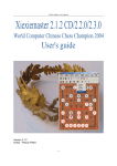
Recommended mounting heights
Men
Women
Children 4-7 years
Children 8-10 years
Children 11-13 years
Children 14-16 years
Handicaped
50"
47"
35"
39"
43"
47"
40"
- from bottom edge of dryer above finished floor (AFF)
(1270 mm)
(1194 mm)
(889 mm)
(991 mm)
(1092 mm)
(1194 mm)
(1016 mm)
Reference ADAAG
Reach LIMIT (unrestricted)
All Approaches
Operation
AFF (maximum)
48"
(1219 mm)
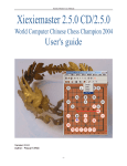
Circuit Diagram
MODEL # 0141 100-120Vac
MODEL # 0144 208-240Vac
NOTE
Thermal Switch 16A
on Heater element
P/N A0090
(Brown)
The ground wire must be connected
to the dryer's backplate.
Service by qualified electrician ONLY.
Supply line 75 C requirement.
Do not daisy chain the ground wire.
Connect to 20A branch circuit ONLY.
L1
(Blue)
N/L2
CIRCUIT BOARD
0141 P/N A0097
0144 P/N A0098
1
2
3
(Brown)
(Black)
(Gray)
Motor With Thermal Switch 2A
0141 P/N A0095
0144 P/N A0110
G
Motor Capacitor
0141 5uF P/N A0101
0144 1.2uF P/N A0102
(G/Y)
Heater Assembly With
Thermal Cut-Off 16.7A
0141 1700W@120Vac 8.5WP/N A0091
0144 1700W@240Vac 28.5WP/N A0092
Hands-Free operation.
Shake excess water from hands.
Place hands under the outlet to start operation.
Rub hands lightly and rapidly. User may flip-tilt
nozzle to dry face.
Stops automatically after hands are removed.
Nozzle returns to original position when
released by user.
Cleaning and Maintenance
Periodic cleaning of the unit is recommended to ensure optimum performance.
Disconnect the electrical supply.
Remove the two cover-mounting screws.
Remove the cover.
Clean all dust lint from the interior of the dryer.
Wipe the cover with a damp cloth and mild
cleaning solution. Do not Soak. Never use
abrasives to clean the cover.
Replace the cover. Do not over tighten the screws.
Warranty
All of our dryers are designed and manufactured to provide years of dependable performance.
Component parts are guaranteed to be free of defects in material and workmanship for a period of
Ten years. This guarantee will be honored provided that the dryer is installed and maintained in
accordance with the instructions. Parts damaged during the Installation are the purchaser's
responsibility. ASI's warranty covers defects exclusively, and only liability for the replacement of
defective parts will be accepted. This warranty does not cover wear and tear, or misuse and abuse.
Transportation, freight costs and labor are also excluded. Defective parts must be returned prepaid,
accompanied by the unit serial number, to the point of purchase. This warranty is granted solely to
the original purchaser of the unit and is subject to registration.
06092857
3
www.americanspecialties.com
Instructions and Parts Manual
Hand Dryer Operating
Surface-mounted Automatic hand dryer
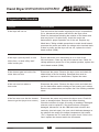
Diagnostics and Remedies
Symptom
Corrective Action
If the dryer will not run
First ensure that the breaker supplying the dryer is operational.
If it is, disconnect the power and remove the dryer cover.
Check for obstructions blocking the rotation of the blower and
clear any found. If it spins freely, check the motor and
thermostat for proper operation out of the unit. Replace any
failed items. Taking suitable precautions to avoid shock hazard,
reconnect the power and check for voltage at the terminal block.
If there is power and the dryer will not run, replace the circuit
board module (CBM) .
If the dryer cycles by itself, or runs
all the time, or shuts off by itself
while in mid-cycle
Ensure that there is no obstruction on or in front of the
infra-red sensor. Clean any dirt off the sensor lens. Check for
voltage spikes on power line. If the problem persists, replace the
circuit board module (CBM).
If the element gets hot but the fan
motor does not turn
Disconnect the power. Remove the dryer cover and check for
obstructions in the fan housing. Damaged fans must be
replaced. If there are no obstructions, replace the motor.
If the unit runs but makes a
buzz noise
Disconnect the power. Remove the dryer cover and check the
fan for obstructions and/or rubbing on the housing as it rotates.
Remove any obstructions and replace fan if the rubbing condition
exists.
If the fan motor runs but the element
does not get hot (Dryer blows cold air)
Disconnect the power and remove the dryer cover. Check for
loose or damaged wires. Remove the blower housing.
Check the element for signs of burning or breakage. Damaged
element must be replaced. If the element does not appear
damaged, disconnect it at the CBM and check element wire
continuity (see tech spec). An open circuit indicates damage to
the element wire and to the integral temperature limit control
(TLC). Separate the TLC and test for open circuit. If this is the
case, replace the element and/or the thermostat.
06092857
4
www.americanspecialties.com
Instructions and Parts Manual
Hand Dryer Operating
Surface-mounted Automatic hand dryer
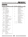
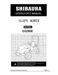
Repair parts list
Key Part #
1
2
3
4
5
6
7
8
9
10
11
12
A0085
A0086
A0087
A0088
A0089
A0090
A0091
A0092
A0093
A0094
A0095
A0110
A0096
A0097
A0098
13 A0099
14 A0100
15
A0101
A0102
16 A0103
17 A0011
18 A0104
19 A0010
20 A0012
21 A0029
22
A0111
A0107
23 A0068
24
25
26
27
28
29
30
31
A0064
A0065
A0108
A0109
A0114
-
06092857
Description
Cover
Lock plate
Teflon washer
Air outlet Nozzle
Axle shaft
Thermostat (TLC)
Heater assembly
100-120Vac 8.5W
208-240Vac 28.5W
Blower wheel
Blower housing
Motor
1/8HP @120Vac
1/8HP @240Vac
Motor Bracket
Circuit Board Module (CBM)
100-120Vac
208-240Vac
Security hex cap head 1/4"-20
x5/8" screw with lock washer
Security hex wrench 4mm
Motor Capacitor
100-120Vac 5uF
208-240Vac 1.2uF
Air outlet grille
Grounding screw with cup
Base plate
Terminal block
Nylon Cable Clamp ¯5/16"
Nylon Hole Bushing
Rating label
100-120Vac
208-240Vac
CAUTION DISCON PWR
Label
CAUTION 20A Label
S/N Barcode Label
Spring
Fixed plate
Shelter plate
Snap pin (M6))
Screw M4x10, philips pan head
SS Washer
Qty
Key Part #
1
1
2
1
2
1
32
-
33
-
34
-
1
1
1
1
35
-
36
-
1
1
1
37
-
38
39
-
1
1
2
40
-
1
41
-
1
1
1
1
1
1
1
1
42
A0112
43
A0113
Description
Screw (M4x6),headless
set (with 2mm hex key)
Screw M3x6,
philips pan head
Screw M4x5,
philips pan head with
external tooth lock washer
Screw M4x8,
philips pan head with
spring washer
Self Threading Screw M3x8,
philips pan head
Self Threading Screw ¯1/4"x
2-1/2", philips pan head
Cable ties not shown
Screw M4x10,
philips pan head with
external tooth lock washer
Screw M3x16,
philips pan head
Screw M5x10,
philips pan head with
spring washer
Mylar shield with
L1,N/L2,G marked
Circuit Diagram Label
Qty
3
2
8
1
3
4
4
2
2
2
1
1
1
1
1
1
1
1
1
1
2
2
2
5
www.americanspecialties.com
Instructions and Parts Manual
Hand Dryer Operating
Surface-mounted Automatic hand dryer
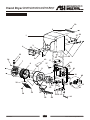
Assembly Diagram
30
2
1
27 29
26
31
4
32
3
33
6
34
22
23
5
43
7
8
17
24
37
20
39
21 41
34
9
18
42
32
10
36
16
34 11
25
19
40
12
13 39 15
36
06092857
35
6
28
14
www.americanspecialties.com