1
Quickie Pulse 6 Service Manual
©2011 Sunrise Medical Inc.
111425 Rev B
Quickie Pulse 6 Service Manual Contents
Introduction
Basic Setup
Motor - Drive Gear engaged
Motor - Free-wheel
Multimeter Tutorial
The Multimeter
The Probes
The Ports
Symbols
Health and Safety
Good Working Practices
Battery Safety
Battery Chargers
EMI Warnings
Electro Static Discharge
Batteries
Battery Diagnostics
Battery Types
VR2 Remote Controller
VR2 Plugs/Connectors
R-NET Remote Controller
R-NET Remote Controller w/Display
R-NET Plugs/Connectors
Main Wiring Diagram VR2 (PLS)
Main Wiring Diagrams Rnet (PLS)
Main Wiring Diagram VR2 and RNET
(PLS6A/PLS6B)
Main Wiring Diagrams Actuators
(PLS6A/PLS6B)
VR2 Dual Attendant System Connection
Basic Tool List
Battery Connection Test
Check Battery Wire Harness
Circuit Breaker Test
Main Harness
Section 2
VR2 Remote Controller Display
The Maximum Speed Indicator Ripples
The Maximum Speed Indicator Flashes
Battery Gauge is Steady
Battery Gauge Flashes Slowly
Battery Gauge Steps Up.
Battery Gauge Blinks Once Every 2.5 Seconds
Battery Gauge Flashes Rapidly
Section 3
VR2 Controller Diagnostic Codes
One Bar - Low Battery Voltage
Two Bars - Left Motor Disconnected
PAGE 2
SEPT 2011
0.1
0.2
0.2
0.2
0.3
0.3
0.3
0.3
0.4
0.5
0.5
0.5
0.6
0.6
0.8
0.9
0.10
0.11
0.12
0.13
0.14
0.15
0.16
0.17
0.18
0.19
0.20
0.21
1.1
1.2
1.2
1.2
2.1
2.1
2.1
2.1
2.1
2.1
2.1
2.1
Three Bars - Left Motor Wiring Trip
3.2
Four Bars- Right Motor Disconnected
3.2
Five Bars - Right Motor Wiring Trip
3.3
Six Bars - Charger Connected
3.4
Seven Bars - Possible Joystick Trip
3.4
Seven Bars + Speed Profile Indicator error
3.4
Eight Bars - Possible Control System Trip
3.4
Nine Bars - Solenoid Brake Trip
3.5
Ten Bars - High Battery Voltage
3.5
Section 4
R-net Troubleshooting Procedures
4.1
Chair Will Not Power Up
4.1
R-net Troubleshooting Procedures (cont.)
4.2
Section 5
R-net Fault Codes
5.1
Power Chair Displays a Fault on the Hand Control or
Omni
5.1
Table 1, Error Codes
5.1
Example of R-10 Fault Isolation
5.4
Power Chair Will Not Drive Full Speed
5.4
Power Chair Will Not Drive in Creep Speed When
Tilted
5.6
Tilt Will Not Operate
5.7
Section 6
Motor/Gearbox Inspection
6.1
Section 7
Removal Procedures
7.1
Battery Removal
7.1
Battery Installation
7.3
Motor and Gearbox Removal
7.4
Motor Removal for chairs after
S/N PLS-101919 and s/n prefix PLS6A &PLS6B 7.6
Control Module Removal
7.7
Shock Removal
7.9
Front Caster Arm Removal
7.10
Rear Caster Arm Removal
7.12
Front or Rear Caster Fork Removal
7.13
Caster Removal
7.14
Tilt Actuator and Micro-Switch Removal
7.15
Section 8
Seat/Back Width adjustment
8.1
Legrest adjustment
8.4
Back-rest Angle Adjustment
8.5
Powered elevating or articulating legrest
8.6
3.1
3.1
3.1
PULSE 6 SERVICE MANUAL
SUNRISE MEDICAL
Introduction
Please read and follow instructions in this service manual before attempting to troubleshoot or repair
this product for the first time. If there is anything in this Service Manual that is not clear, or if you require
additional Technical assistance, contact Sunrise Medical at: (800) 333-4000 option 2, then option 1.
Safely troubleshooting and/or repair of this product depends on your diligence at following the
instructions within this manual. Sunrise Medical is not responsible for injuries or damage resulting
from a person’s failure to exercise good judgement and/or common sense.
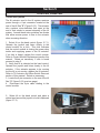
This Service Manual is intended as a troubleshooting guide for the Quickie Pulse 6. Photographs and
content may differ from the actual products in some cases due to changes in specifications and other
factors.
This Service Manual is intended for use by persons with a basic working knowledge and the skills
required in servicing and maintaining Power Wheelchairs. Persons without a general working knowledge
and expertise in the servicing of this product should not carry out troubleshooting procedures. This
can result in personal safety issues, problems with future servicing, and/or damage to the unit.
Parts, configuration, and/or specifications of Products included in this Service Manual
are subject to change without prior notice.
There are warning symbols used in this document that are
intended to focus attention on any hazard that could effect the
safety of the individual troubleshooting the Power Wheelchair
covered by this Service Manual.
Click !
For up-to-date parts, and the latest version of this Service Manual go to:
www.sunmed.com
and click on the Parts Search button
SUNRISE MEDICAL
PULSE 6 SERVICE MANUAL
SEPT 2011
PAGE 0.1
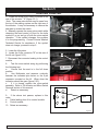
Basic Setup
When setting up the components of the chair, complete the following checklist to ensure proper and
safe operation of the equipment.
Check :
□ Are the batteries fully charged?
a. Test battery voltage with D.C. meter across the terminals of batteries. The measurement should
be above 12 volts D.C. (Note: a fully charged battery is between 12.9 and 13.1 VDC)
b. If not, fully charge the batteries.
□ Are all necessary power components installed and connected ?
a. Input device (normally Joystick)
b. Cable from Joystick to the Bus Line
c. Control Module; for the Pulse located at back of chair behind shroud
d. Are batteries installed correctly? (refer to Section 1 of this manual
□ Are all necessary connections fastened and fully engaged?
a. Battery connectors to the batteries
b. Cable between Joystick and the Control
c. Both Motor Connectors to the Control Module.
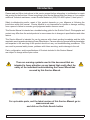
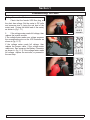
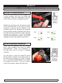
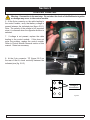
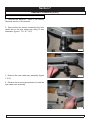
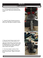
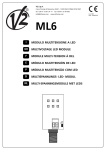
□ Is the Drive Gear engaged? See (figures .2.1 and .2.2)
a. With the power off, the chair should not move if pushed from behind.
b. If the chair moves when pushed, the drive gear needs to be engaged on both motors.
c. Does Display light up when Power On/Off switch is depressed?
If no - Follow checklist a second time, then refer to the section on Diagnostics.
If yes – The Power Wheelchair is ready to drive!
Motor - Drive Gear engaged
Motor - Free-wheel
fig .2.1
PAGE 0.2
SEPT 2011
PULSE 6 SERVICE MANUAL
fig. 4.3.4
SUNRISE MEDICAL
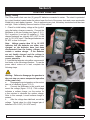
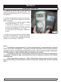
Multimeter Tutorial
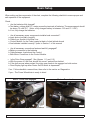
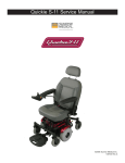
The Multimeter
MULTIMETER
For Powerchairs, the multimeter is one of the
most useful tools in the toolbox. It can be used
to check wires, shorts, voltages, resistance, and
all manner of electrical circuits. This tutorial is
designed to help clarify the symbols and socket
options.
The Probes
Probes are found on various multimeters. The
Probes connect the meter to the circuit. Simply
touch them to the directed area with the Mulitmeter on the correct settings, and read the display.
Follow instructions in this manual carefully to
avoid errant reads.
PROBES
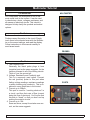
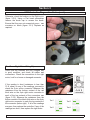
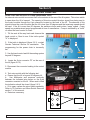
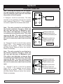
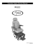
The Ports
1. The Common Port.
Generally, the black probe plugs in here
(negative) and as the name suggests, it’s the
common element to all of the testing circuits.
Think of it as the ground rail.
2. Voltage, Resistance and Continuity port.
This is a commonly used option. Connect
the red (positive) probe to this port when
finding voltage readings, resistance readings
or when checking wire continuity. This is explained in more detail later in the tutorial.
3. Current up to 300mA.
This port is used for “counting electrons” in
a circuit, and thus their rate of flow (current
being the flow of electrons). You’ll notice that
this side is “fused”, so that you don’t end up
melting the meter’s circuits.
4. Current up to 10A.
Same as above, except it can take more current, as the name suggests.
SUNRISE MEDICAL
PULSE 6 SERVICE MANUAL
PORTS
SEPT 2011
PAGE 0.3
Multimeter Tutorial
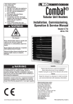
Symbols
This section describes the basic symbols used in a typical
multimeter.
AC
ALTERNATING CURRENT Use this when you want to test something
that has AC current running through it. Typically you’d want to test the
voltage of an inverter (for cold cathodes or neons) or a similar device.
DC
DIRECT CURRENT. This is the type of electrical power produced by a
battery. With a battery connector, the black wire(s) should be connected
to the negative(-) terminal of the battery and should be considered
the common ground. The red wire(s) should be connected to the
positive(+) terminal of the battery and is considered the “hot” lead.
Voltage
This means Voltage or Potential Difference. It will measure the
potential difference between the two probes. To measure voltage,
connect the positive probe to a port that is marked “V” or Voltage.
Note: “mV” means milli-volts = .001 Volt
Current
Since current is measured in Amps and the readout value is in
amps, the symbol "A" is used. On this setting the unit measures
current that is flowing through the part of the circuit between
the two probes (the meter itself). Typically, you need to plug the
positive terminal into a port marked “A” or Current. You need to put
the meter “In Series” in the circuit to use this feature correctly.
Resistance
This symbol represents Resistance and is measured in Ohms.
You can use this setting to measure the resistance between two
points; for example across a piece of wire or a resistor (to check its
value). If you don’t have a continuity check, then this can be used
to check for shorts. Any value below 0.05 Ohms constitutes a short,
meaning that whatever the probes are attached to is connected
electrically.
Continuity
A commonly used function. By putting a current through the
two terminals (the same as the Ohm-meter function) it can be
determined if the resulting value is within the “contact” range, this
is signified with a beep. The feature found on some multimeters
enables you to check for shorts without taking your eyes off your
work. Other meters signify this with a small flashing light.
PAGE 0.4
SEPT 2011
PULSE 6 SERVICE MANUAL
SUNRISE MEDICAL
Health and Safety
Good Working Practices
Health and Safety
While working on powered mobility products, it is essential to observe
good working practices. Below are a series of safety guidelines and
recommendations. Please note that these precautions are intended to serve
only as a guide, not to supersede or replace any safety statute, NHS or other
safety regulations.
General
• Always wear suitable protective clothing when handling batteries.
• Always wear suitable eye protection when drilling or inspecting.
• When safe to do so, wear protective gloves when handling the running
gear or batteries, as these parts are exposed to paths, parks etc.
• If the drive wheels have to be raised off the floor, always use a pair
of axle stands to secure the vehicle.
Battery Safety
•
•
•
•
•
•
•
•
•
•
•
•
•
•
Use extra caution when working with batteries.
Always make sure that the batteries are disconnected from the device
before commencing work.
Always check that the battery charger is disconnected from the device
/batteries before commencing work.
Do not smoke while working on this device.
Keep batteries away from all sources of ignition.
Do not place objects on top of the batteries.
Always keep someone close to your work area so that they may come
to your assistance if needed.
Always wear personal protection when handling batteries, including,
eye/face protection and gloves.
Make sure there is easy access to soap and water in case of acid
spills.
Avoid touching eyes or unprotected parts of the body while working on
batteries.
Remember that non-sealed batteries can contaminate any packaging,
housing, or boxes they may have been transported in so handle all
packaging with care, especially during disposal.
If battery acid should come into contact with bare skin or clothing, be
sure to wash contacted area immediately, using plenty of soap and
water. If battery acid enters the eyes, flush with running cold water for
as long as possible while medical help is being sought.
When the tops of batteries are exposed, take extra care when working
on or around the terminals.
Do not allow metal tools to drop on to or touch the exposed terminals
of the batteries or other exposed connections, as this could cause a
short circuit, which may result in an explosion.
SUNRISE MEDICAL
PULSE 6 SERVICE MANUAL
SEPT 2011
PAGE 0.5
Health and Safety
•
Remove personal items of jewelry, such as rings, watches, chains
etc. before working on batteries. Such items could cause short
circuits resulting in serious burns.
• Batteries are constructed of heavy materials. Therefore moving
batteries requires appropriate lifting techniques. Safety footwear
should also be worn. In addition, disposal of old batteries
requires correct procedures. Contact your local authority for their
recommendations.
Battery Chargers
•
•
•
•
•
Remember battery chargers are connected to household current.
Always observe all guidelines and laws relating to electrical
equipment.
Never operate the battery charger in wet or damp conditions.
If you think that the charger has been exposed to water or excessive
dampness, do not use it. Return the unit to the dealer/supplier for
inspection/replacement.
If you think the battery charger is defective or is visibly damaged,
return the unit to the dealer/supplier for inspection.
EMI Warnings
•
•
•
•
EMI means electromagnetic (EM) interference (I). EMI comes from
radio wave sources, such as radio transmitters and transceivers. A
“transceiver” is a device that both sends and receives radio wave
signals.)
There are a number of sources of intense EMI in our daily
environment. Some of these are obvious and easy to avoid. Others
are not, and we may not be able to avoid them.
Powered wheelchairs, although tested in accordance with EMC
guidelines, may be susceptible to electromagnetic interference (EMI)
emitted from sources such as, radio stations, TV stations, amateur
radio (HAM) transmitters, two-way radios, and cellular phones.
EMI can also be produced by conducted sources or electro-static
discharge (ESD).
What effect can EMI have?
1. EMI can, without warning, can cause a power chair to:
• Release its electronic brakes
• Move by itself
• Move in unintended directions.
If any of these occur, severe injury could result.
2. EMI can damage the control system of a power chair, resulting in a
safety hazard and/or costly repairs.
PAGE 0.6
SEPT 2011
PULSE 6 SERVICE MANUAL
SUNRISE MEDICAL
Health and Safety
Sources of EMI
1. Hand-Held Transceivers: Antenna is usually mounted directly on the unit.
These include:
• Citizens band (CB) radios
• “Walkie-talkies”
• Security, fire and police radios
• Cellular phones
• Lap top computers with phone or fax
• Other personal communication devices
Note - These devices can transmit signals while they are on, even if not in use.
The wheelchair should be switched off when not in use.
2. Medium-Range Mobile Transceivers: include two-way radios used in police
cars, fire engines, ambulances and taxi cabs. The antenna is usually mounted
on the outside of the vehicle.
3. Long-Range Transceivers: These include commercial radio and TV broadcast
antenna towers, amateur (HAM) radios, and alarm systems.
NOTE- The following are Not likely to cause EMI problems: Lap-top computers
(without phone or fax), cordless phones, TV sets or AM/FM radios, CD or tape
players.
EM energy rapidly becomes more intense as you get closer to the source. For
this reason, EMI from handheld devices is of special concern. A person using
one of these devices can bring high levels of EM energy very close to a power
chair without the user’s knowledge.
Immunity level
The level of EM is measured in volts per metre (V/m). Every power wheelchair
can resist EMI up to a certain level. This is called its “immunity level”. The higher
the immunity level, the less the risk of EMI. It is believed that a 20 V/m immunity
level will protect the power wheelchair user from the more common sources of
radio waves.
For the Pulse 6, the configuration tested and found to be immune to at least 20
V/m is: a right-handed mounted joystick system, 18” seat width, 18” seat depth,
dual-post height-adjustable armrests, fixed tapered legrests with one-piece solid
footplate and Gp 24 gel cell batteries.
The following dealer installed speciality input devices have an unknown effect on
the immunity level because they have not been tested with the Quickie control
systems:
• Breath Control (“Sip n Puff”)
• Tri-Switch Head Array
• Proximity Head Array
• Proportional Mini-Joystick/Chin Control
• Buddy Button
• Wafer Board
SUNRISE MEDICAL
PULSE 6 SERVICE MANUAL
SEPT 2011
PAGE 0.7
Electro Static Discharge
To help prevent Electro Static Discharge (ESD) the following proper
handling techniques should be followed:
ESD:
• Do not place Printed Circuit Boards or their containers near
sources of strong electrical fields (such as above a CRT).
• To avoid the occurrence of static charge or discharge due to
friction, keep the Printed Circuit Boards separate from one another and do not stack them directly on top of one another if not
protected by antistatic bags.
• Store each Printed Circuit Board in an antistatic bag with an
external cushioning bubble-wrap layer until assembled to
wheelchair. Antistatic bag must have metal content to protect
the printed circuit board. Gray bag protects from ESD, pink bag
or bubble wrap does not protect as well.
• Always wear an ESD preventive wrist or ankle strap when handling electronic components. Connect one end of the strap to
an ESD jack or an unpainted metal component on the system
(such as a captive installation screw).
• Handle Printed Circuit Boards by the edges only; avoid touching the Printed Circuit Board and connector pins.
• Place any removed Printed Circuit Board on an antistatic surface or in a static shielding bag.
• Avoid contact between the Printed Circuit Boards and clothing.
The wrist strap only protects the card from ESD voltages on the
body; ESD voltages on clothing can still cause damage.
• Make sure that the Printed Circuit Board power is off by disconnecting the seating harness prior to attaching or removing
printed circuit board.
Printed Circuit Board Flexing:
• The printed circuit board has surface-mount components that
may break when the board is flexed. To minimize the amount
of board flexing, observe the following precautions:
• Hold the printed circuit board only by the edges.
• Do not place the printed circuit board on a hard surface.
• Tighten board mounting screws only hand tight (torque12.4
in lbs/1.4Nm) in a cross pattern to reduce stress on mounting
holes and PCB board material.
PAGE 0.8
SEPT 2011
PULSE 6 SERVICE MANUAL
SUNRISE MEDICAL
Batteries
Safety
If mishandled batteries can be dangerous and hazardous.
•
•
•
•
•
•
All mobility batteries, whether wet type or gel/sealed type, contain
lead and sulfuric acid. Both of these materials are toxic and in the
case of sulfuric acid, highly corrosive. Additionally, when batteries are
charged, they produce hydrogen gas which is “highly” flammable and
can cause explosion. This is why proper handling is mandatory at all
times.
Battery explosion - This is frequently the result of too low an acid/
electrolyte level in the battery, which allows high concentrations of
hydrogen to build up. This is possible with all batteries if improper
charging or battery failure occurs, but not common in gel/sealed
batteries.
< KEEP SPARKS AND FLAMES AWAY FROM BATTERIES >
Burns - dropping a wrench or screwdriver across battery terminals
results in sparks, and intense heat. Improper assembly of battery
boxes or battery box wiring may short the battery through the wiring
and produce a possible electrical fire.
Electronic damage - batteries that are improperly wired can short out
electronic chair components resulting in expensive repairs.
Pollution - improper disposal of batteries could damage the
environment. All batteries should be disposed of through a reliable
battery recycler.
Battery Charge Cycle Illustration
Typical Flooded Battery
Discharge
POS = PbO2
NEG = Pb
ACID = H2SO2
-
+
+
+
+
+
+
+
+
+
+
-
+
-
+
-
+
-
+
-
+
-
+
-
+
-
+
-
+
-
+
POS = PbSO4
NEG = PbSO4
ACID = H2O
-
H2O
H2SO2
Recharge
As battery discharges, the sulfate from the electrolyte forms on the plates.
As battery recharges, the sulfate is driven back into the electrolyte
SUNRISE MEDICAL
PULSE 6 SERVICE MANUAL
SEPT 2011
PAGE 0.9
Batteries
Battery Diagnostics
Batteries should last an average of 1 to 1.5 years.
These are some Factors that affect battery performance:
• Maintenance - Poor maintenance.
• Charging - Improper charging shortens battery life.
• Chair Components - Malfunctioning electronics, bad motors, electric brakes, and corroded
wiring are also capable of degrading the battery performance.
Battery Servicing and Replacement
Automobile batteries, which are used for starting, are tested with a load tester to assure a high rate of
energy production in a short burst.
Deep-cycle batteries produce energy more slowly and are designed to hold up to constant
discharging and recharging. Testing a deep-cycle wheelchair or scooter battery requires different
procedures than an automobile battery.
A routine for testing deep-cycle batteries should follow these guidelines:
Never replace just one battery at a time. This will create an imbalance when charging and ultimately
damage both batteries.
Check batteries for a voltage difference. A voltage difference of more than .4 volts D.C. is a true
indicator of a bad battery.
Voltage test - A dead battery cannot be effectively tested, yet many people mistakenly try to do just
that.
Any battery that reads 11.0 volts or less is technically dead.
To perform any testing, especially a load test:
A. Batteries must be charged
B. The top charge must be taken from fully charged batteries if charge rate has just finished.
The voltmeters on load testers are not accurate enough to establish a state of charge.
•
•
•
Load Test - This test can only be done on fully charged batteries and can only diagnose one
type of problem, an internal short.
Capacity/Discharge Test - This is the only accurate way to test a deep-cycle battery for adequate
running time. The problem with this test is that it is time consuming.
Current / Voltage check with a regular interval check - Another way of truly knowing how much
time your battery will last, but it is also time consuming.
PAGE 0.10
SEPT 2011
PULSE 6 SERVICE MANUAL
SUNRISE MEDICAL
Batteries
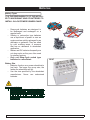
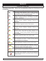
Battery Types
IT IS THE RESPONSIBILITY OF THE INSTALLER TO KNOW WHAT KIND OF BATTERIES TO
INSTALL IN A CUSTOMER’S WHEELCHAIR!
•
•
•
•
Deep-cycle batteries are designed to
be discharged and recharged on a
regular basis.
Starting or automotive type batteries
use a rapid burst of power to start an
engine and are quickly recharged by an
alternator or generator. They are rated
by cold cranking amps, a measure
that has no relevance to wheelchair
application.
Marine and RV batteries frequently are
not deep-cycle as they are often used
for starting engines.
Only use Deep-Cycle sealed type
batteries in a wheelchair.
22 NF
Battery Size
• Batteries function as a power wheelchair’s
fuel tank. The larger the group size, the
farther the wheelchair will go.
• Use the size specified by the wheelchair
manufacturer. Never use undersized
batteries.
Battery Installation.
• Batteries installed incorrectly can blow the
fuse for this system. Pay careful attention
to install the battery harness across both
batteries instead of to each of the batteries
individually.
SUNRISE MEDICAL
PULSE 6 SERVICE MANUAL
SEPT 2011
PAGE 0.11
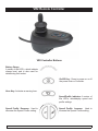
VR2 Remote Controller
VR2 Controller Buttons
Battery Gauge
A series of ten LED’s, which indicate
charge level, and is also used for
determining fault codes.
On/Off Key- Press to power on or off
the power chair or Controller.
Horn Key- Activates a warning horn.
Speed/Profile indicator- A series of
five LED’s, whichdisplay speed and
profile settings
Speed/ Profile Decrease. Used to
decrease the Speed/ Profile setting.
PAGE 0.12
SEPT 2011
Speed/ Profile Increase. Used to
Increase the Speed/ Profile setting.
PULSE 6 SERVICE MANUAL
SUNRISE MEDICAL
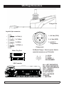
VR2 Plugs/Connectors
Charger Port
Joystick 4pin connector
1 = 24 Vdc (POS)
1
2
4 = Red (+)
3
3 = Yellow
2 = 0 Vdc (NEG)
2 = White
3 = Inhibit 1/
Programmer
1 = Black (-)
Charger port
On-Board Charger - Used to power Switchcontrolled actuators and Tilt Inhibit.
Motor Plug Port
+
_
_
+
VR2 Controller
SUNRISE MEDICAL
1 = 24 Vdc
2 = 0 Vdc
3 = INHIBIT 1/
PROGRAMMER
M1 = LEFT SIDE MOTOR
M2 = RIGHT SIDE MOTOR
JSM = JOYSTICK MODULE
INH-2 = INHIBIT 2
A1 = ACTUATOR 1
A2 =ACTUATOR 2
OBC = ON BOARD
CHARGER
+ - =BATTERY
PULSE 6 SERVICE MANUAL
SEPT 2011
PAGE 0.13
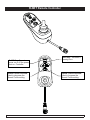
R-NET Remote Controller
Horn Key- Activates a
warning horn.
On/Off Key- Press to
power on or off the power
chair or Controller.
Speed/ Profile Increase.
Used to Increase the
Speed/ Profile setting.
Speed Profile Decrease.
Used to decrease the
Speed/ Profile setting.
PAGE 0.14
SEPT 2011
PULSE 6 SERVICE MANUAL
SUNRISE MEDICAL
R-NET Remote Controller w/Display
On/Off Key- Press to power
on or off the power chair or
Controller.
Horn Key- Activates a
warning horn.
Speed/ Profile Increase.
Speed Profile Decrease.
Used to decrease the
Speed/ Profile setting.
SUNRISE MEDICAL
Used to Increase the
Speed/ Profile setting.
PULSE 6 SERVICE MANUAL
SEPT 2011
PAGE 0.15
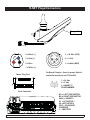
R-NET Plugs/Connectors
Charger Port
1
2
1 = 24 Vdc (POS)
4 = Black (-)
1
2
3 = Red (+)
4
3
3
2 = Blue
2 = 0 Vdc
3 = Inhibit (NEG)
1 = White (-)
On-Board Charger - Used to power Switchcontrolled actuators and Tilt Inhibit.
Motor Plug Port
_
+
1 = 24 Vdc
2 = 0 Vdc
3 = INHIBIT 1/
PROGRAMMER
_
+
Rnet Controller
M1 = LEFT SIDE MOTOR
M2 = RIGHT SIDE MOTOR
INH-2 = INHIBIT 2
A1 = ACTUATOR 1
A2 =ACTUATOR 2
OBC = ON BOARD
CHARGER
+ - =BATTERY
PAGE 0.16
SEPT 2011
PULSE 6 SERVICE MANUAL
SUNRISE MEDICAL
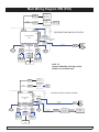
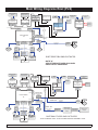
Main Wiring Diagram VR2 (PLS)
4-Way
Tyco Bus
VR2
Hand Control
Inhibit2
Inhibit3
4-Way
Intech
Motor
3-Way P G D
C harger
Power Module
VR2
2-Way P G D
Inhibit
2-Way PGD
Actuator
4-Way
Tyco Bus
4-Way
Intech
Motor
2-Way VR2
Intech Battery
B AS E
VR2 BUS
SPLITTER
Offboard
Charger
S E AT
VR2
Attendant
Hand Control
DR IV E -T HR U
HAR NE S S
4-Way
Tyco Bus
VR2 DRIVE-THRU SINGLE ACTUATOR
4-Way Amp
Mate-N-Loc
ACTUATOR ADAPTOR
HARNESS
6-Way
Mini-Fit J r.
Switch
6-Way
Mini-Fit J r.
ACTUATOR
HARNESS
Seat Tilt
2-way
SB50
Red
Drive
Left
POWER HARNESS
Circuit
Breaker
Fuse
Red
2-way
SB50
Black
Drive
Right
Fuse
Black
Red
Battery
Black
Battery
SEE NOTE
"A"
VR2
Attendant
Hand Control
4-Way
Tyco Bus
VR2
Hand Control
Inhibit2
Inhibit3
4-Way
Intech
Motor
Drive
Left
2-way
SB50
Red
POWER HARNESS
Circuit
Breaker
Fuse
Red
2-Way VR2
Intech Battery
Black
VR2 DUAL-TOGGLE SINGLE ACTUATOR
ACTUATOR ADAPTOR
HARNESS
6-Way
Mini-Fit J r.
4-Way
Intech
Motor
Switch
6-Way
Mini-Fit J r.
ACTUATOR
HARNESS
4-Way Amp
Mate-N-Loc
Seat Tilt
2-way
SB50
Black
Drive
Right
DUAL-TOGGLE
HARNESS
4-Way Amp
Mate-N-Loc
Dual-Toggle
Single Actuator
Driver
3.5 mm Stereo
Phone Jack
Dual-Toggle
Switch
Fuse
Red
Battery
3-Way P G D
C harger
Power Module
VR2
Offboard
Charger
B AS E
2-Way PGD
Actuator
2-Way P G D
Inhibit
4-Way
Tyco Bus
4-Way
Tyco Bus
S E AT
VR2 BUS
SPLITTER
NOTE "A"
CIRCUIT BREAKER USED ON CHAIRS
PRIOR TO PLS-100808 ONLY
Black
Battery
SEE NOTE
"A"
SUNRISE MEDICAL
PULSE 6 SERVICE MANUAL
SEPT 2011
PAGE 0.17
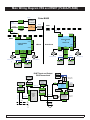
Main Wiring Diagrams Rnet (PLS)
4-Way
PGD Bus
Bluetooth Modu le
4-Way
PGD Bus
2-Way PGD
Actuator
Inhibit2
Inhibit3
4-Way
Intech
Motor
9-Way "D"
Connector
ONMI
Universal Specialty
Control Interface
Remote
Switch Option
Infrared
Device(s)
4-Way PGD
Bus
3-Way Neutrik
Charge Port
4-Way
PGD Bus
ACTUATOR ADAPTOR
HARNESS
6-Way
Mini-Fit J r.
4-Way
Intech
Motor
2-Way VR2
Intech Battery
9-Way "D"
Connector
Charger
4-Way Amp
Mate-N-Loc
3-Way P G D
C harger
Power Module
EL
Specialty Input
Device
Joystick
B AS E
4-Way PGD
Bus
Switch/
Potentiometer
Option
DR IV E -T HR U
HAR NE S S
4-Way
PGD Bus
4-Way
PGD Bus
4-Way PGD
Bus
4-Way
PGD Bus
2-Way P G D
Inhibit
Output Modle
Specialty Input
Device
Ext. Switch
Ext. Switch
Attendant Contr ol
Connector Block
4 X CAN
9-Way "D"
Connector
4-Way
PGD Bus
4-Way
PGD Bus
3.5 mm
P hone J ack
4-Way
PGD Bus
3.5 mm
P hone J ack
External 3rd Party
Wireless Devices
S E AT
External 3rd Party
Devices
Switch
6-Way
Mini-Fit J r.
ACTUATOR
HARNESS
Seat Tilt
POWER HARNESS
Circuit
Breaker
Fuse
Red
Drive
Right
Fuse
Black
Black
Red
Battery
R-NET DRIVE-THRU SINGLE ACTUATOR
Battery
SEE NOTE
"A"
External 3rd Party
Devices
NOTE "A"
CIRCUIT BREAKER USED ON CHAIRS
PRIOR TO PLS-100808 ONLY
External 3rd Party
Wireless Devices
4-Way
PGD Bus
4-Way
PGD Bus
Bluetooth Modu le
Output Modle
4-Way
PGD Bus
4-Way
PGD Bus
4-Way
PGD Bus
Ext. Switch
Ext. Switch
Attendant Contr ol
Connector Block
4 X CAN
9-Way "D"
Connector
4-Way
PGD Bus
4-Way
PGD Bus
4-Way PGD
Bus
4-Way
PGD Bus
Switch/
Potentiometer
Option
3.5 mm
P hone J ack
Drive
Left
2-way
SB50
Black
3.5 mm
P hone J ack
2-way
SB50
Red
Specialty Input
Device
9-Way "D"
Connector
Inhibit2
Inhibit3
4-Way
Intech
Motor
Drive
Left
2-way
SB50
Red
POWER HARNESS
Circuit
Breaker
Fuse
Red
2-Way VR2
Intech Battery
Black
ONMI
Universal Specialty
Control Interface
Remote
Switch Option
PAGE 0.18
SEPT 2011
S E AT
B AS E
4-Way PGD
Bus
3-Way Neutrik
Charge Port
4-Way
PGD Bus
4-Way Amp
Mate-N-Loc
020063-040
Switch
6-Way
Mini-Fit J r.
ACTUATOR
HARNESS
Seat Tilt
2-way
SB50
Black
Drive
Right
108277-100
DUAL-TOGGLE
HARNESS
4-Way Amp
Mate-N-Loc
Dual-Toggle
Single Actuator
Driver
3.5 mm Stereo
Phone Jack
Dual-Toggle
Switch
Fuse
Black
Battery
SEE NOTE
"A"
104977-020
Infrared
Device(s)
ACTUATOR ADAPTOR
HARNESS
6-Way
Mini-Fit J r.
4-Way
Intech
Motor
Red
Battery
3-Way P G D
C harger
Power Module
EL
2-Way P G D
Inhibit
2-Way PGD
Actuator
9-Way "D"
Connector
Charger
Joystick
4-Way PGD
Bus
Specialty Input
Device
R-NET DUAL-TOGGLE SINGLE ACTUATOR
NOTE: HARNESS 108277-100 IS INCLUDED IN RETRO ASSEMBLY 110842
PULSE 6 SERVICE MANUAL
SUNRISE MEDICAL
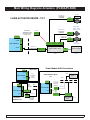
Main Wiring Diagram VR2 and RNET (PLS6A/PLS6B)
102175
batc8ct
VR2
Hand Control
4-Way
Tyco Bus
4-Way
Tyco Bus
SEAT
Offboard
Charger
105375 - 4 Button
105376 - 6 Button
SEAT
101626
118557-100
BASE
4-Way
R-net Bus
4-Way
Tyco Bus
2-Way PGD
Actuator
2-Way
Intech Battery
Black
Drive
Right
104741
4-Way
Intech
Motor
SB50
Drive
Right
2-way
104742
113212 (Pulse 6)
113213 (Pulse 6)
Fuse
Red
104741
SB50
Fuse
Red
Red
Black
Black
113213 (Pulse 6)
Black
Battery
Battery
Battery
External 3rd Party
Wireless Devices
External 3rd Party
Devices
Ext. Switch
Switch/Pot
Option
Attendant Control
108214
4-Way
PGD Bus
4-Way PGD
Bus
4-Way
PGD Bus
Ext. Switch
108316-030
4-Way PGD
Bus
4-Way PGD
Bus
4-Way
PGD Bus
108316-030
108217
108316-050
4-Way
4-Way
PGD Bus PGD Bus
Specialty Input
Device
Connector Block
4 X CAN
108312
Intellegent
Seating
Module
(ISM)
Right or Left
Hand Mount
Remote
Switch Option
Joystick
108207
108210
116525
108316-120
Output Modle
108316-120
R-NET Input and Output
BUS Connections
Bluetooth Module
108218
4-Way
PGD Bus
9-Way "D"
Connector
4-Way
PGD Bus
Inhibit3
Black
Fuse
Red
Battery
Inhibit2
2-way
113351-045
Drive
Left
2-Way
SB50 Black
2-way
104742
SB50
Red
Fuse
Red
4-Way
Intech
Motor
3-Way Neutrik
Charge Port
113212 (Pulse 6)
113351-045
2-Way
Intech Battery
4-Way
Intech
Motor
3.5 mm
Phone Jack
Drive
Left
R-Net EL-90
3.5 mm
Phone Jack
4-Way
Intech
Motor
VR2-90
3-Way PGD
Charger
Inhibit3
2-Way PGD
Inhibit
Inhibit2
Power Module
VR2-90
Power Module
R
-Net EL-90
3-Way PGD
Charger
BASE
2-Way PGD
Actuator
2-Way PGD
Inhibit
102359
(Included with Attendant Control)
VR2 BUS
SPLITTER
Pulse BASE
VR2
Attendant
Hand Control
4-Way
Tyco Bus
Specialty Input
Device
9-Way "D"
Connector
4-Way
4-Way
PGD Bus PGD Bus
108316-120
Infrared
Device(s)
108316-120
SEAT
batc8ct
Offboard
Charger
9-Way "D"
Connector
OMNI
Universal Specialty
Control Interface
Right or Left
Hand Mount
112731
4-Way PGD
Bus
BASE
SUNRISE MEDICAL
PULSE 6 SERVICE MANUAL
SEPT 2011
PAGE 0.19
Main Wiring Diagrams Actuators (PLS6A/PLS6B)
109230
020063-100
ACTUATOR
HARNESS
3-AXIS ACTUATOR DRIVER - TILT
Switch
6-Way
Mini-Fit Jr.
Seat Tilt
020063-160
ACTUATOR
HARNESS
119131
ACTUATOR
SHORTING PLUG
(Use in place of tilt
for legs only.)
6-Way
Mini-Fit Jr.
2-Way PGD
Inhibit
2-Way PGD
Actuator
Inhibit2
6-Way
Mini-Fit Jr.
Right/
Extend
ELR
020063-160
6-Way
ACTUATOR
HARNESS Mini-Fit Jr.
Left/Lift
ELR
6-Way
6-Way
6-Way
Mini-Fit Jr. Mini-Fit Jr. Mini-Fit Jr.
Power Module
3-Way PGD
Charger
Inhibit3
DUAL ELRs:
LEFT: 111206
RIGHT: 111207
116507-150
POWER/INHIBIT 3-Way Molex
Mini-Fit Jr.
HARNESS
113277
Centermount
Switch Controls
DB9
3-Axis Actuator Driver
116509
Inhibit2
Inhibit3
3-Way PGD
Charger
Power Module
Drive Only
2-Way PGD
Inhibit
2-Way PGD
Actuator
116467
SHORTING
PLUG
(7.5 KOhm)
Power Module AUX Connections
Power Module
Thru-Drive
PM Driven Tilt
PAGE 0.20
3-Way PGD
Charger
Inhibit3
4-Way Amp
Mate-N-Loc
6-Way
Mini-Fit Jr.
2-Way PGD
Inhibit
Inhibit2
104977-020
ACTUATOR
ADAPTOR
HARNESS
Power Module
BASE
020063-070
Inhibit3
6-Way
Mini-Fit Jr.
3-Way PGD
Charger
2-Way PGD
Inhibit
Inhibit2
SEAT
4-Way Amp
Mate-N-Loc
BASE
020063-070
3.5 mm Stereo
Phone Jack
Dual-Toggle
Single Actuator
Driver
104977-020 ACTUATOR
ADAPTER
HARNESS
SEPT 2011
Buddy Button
Switch
SEAT
111438-020
DRIVE
THRU
HARNESS
139920
Single Actuator Driver
Tilt
2-Way PGD
Actuator
2-Way PGD
Actuator
139221
PULSE 6 SERVICE MANUAL
TILT:
112563
SUNRISE MEDICAL
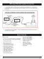
VR2 Dual Attendant System Connection
1. A s shown below, the 4 or 6 button joystick module must be connected to the short branch of
the attendant module intermediate cable and the attendant joystick must be connected to the
long branch.
SHOR T
B R A NCH
L ONG
B R A NCH
2. If these connections are reversed a “7-flash” communications fault will be displayed on the 4
or 6 button joystick module.
Basic Tool List
Basic Tool List
This list of tools will be needed to accomplish
all of the tasks given in this Technical Manual
some are used often.
•
•
•
•
•
•
•
•
•
•
19mm socket wrench
18mm combination wrench
17mm Deep Socket wrench
17mm Open End wrench
13mm combination wrench
13mm" Socket wrench
10mm open end wrench
13mm Open End wrench
5mm socket wrench
3/8 combination wrench
SUNRISE MEDICAL
•
•
•
•
•
•
•
•
•
3mm Hex Key/THandle
4mm Hex Key/THandle
5mm Hex Key/THandle
Phillips screwdriver #2
Cutter for zip-tie
Needle nose pliers
Flat blade screwdriver
3mm or 1/8" Pin Punch
Multi-Meter
PULSE 6 SERVICE MANUAL
SEPT 2011
PAGE 0.21
Section 1
Troubleshooting: No Power
Battery Connection Test
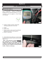
1.
Check that the female VR2 Bus plug on
the chair has voltage. Set the meter to DC volts
and measure pins 4 (using the red lead of the
meter) and 1 (using the black lead of the meter)
as shown in (fig 1.1.1)
2.
If the voltage meter reads full voltage, then
replace the joystick module
If the voltage meter reads zero voltage measure
the corresponding pins on the VR2 controller as
shown in (fig 1.1.2).
If the voltage meter reads full voltage, then
replace the jumper cable. If the voltage meter
reads zero, then measure the Battery Connector
as shown in (fig 1.1.3) If the voltage meter reads
full voltage, replace the controller, or proceed to
the next step.
Fig 1.1.1
Fig 1.1.2
Fig 1.1.3
SUNRISE MEDICAL
PULSE 6 SERVICE MANUAL
SEPT 2011
PAGE 1.1
Section 1
Troubleshooting: No Power (cont.)
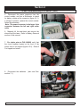
Check Battery Wire Harness
Check that the battery wire harness has the
correct polarity. Set the meter to dc volts and
measure the connector with the red lead on the
+ terminal and the black lead on the negative terminal as shown in (figure 1.2.1). If the voltage is
absent proceed to battery fuse test. If the polarity
is reversed correct battery wiring.
Fig 1.2.1
Battery Fuse
Check that the battery fuse is in good condition.
With the batteries disconnected, set the meter
to ohms and measure the resistance across the
fuse. see (figure 1.2.2). If the meter reads more
than one ohm, change the wiring harness, or else
proceed to the next step.
Fig 1.2.2
Circuit Breaker Test
For chairs prior to PLS-100808
To check the circuit breaker set the meter to ohms
and measure the resistance across the circuit
breaker as shown in (figure 1.2.3) if the meter
reads more than 1 ohm, then change the circuit
breaker, otherwise proceed to next step.
Fig 1.2.3
Main Harness
If the above steps did not correct the problem,
change the main harness.
PAGE 1.2
SEPT 2011
PULSE 6 SERVICE MANUAL
SUNRISE MEDICAL
Section 2
VR2 Remote Controller Display
The Maximum Speed Indicator Ripples
Indicates that the wheelchair is locked. To unlock the wheelchair, deflect the joystick forwards until the
control system chirps. Then deflect the joystick in reverse until the control system chirps. Release the
joystick, there will be a long beep. The wheelchair is now unlocked. To lock the wheelchair, while the
control system is switched on, depress and hold the on/off button. After 1 second, the control system
will chirp. Now release the on/off button, deflect the joystick forwards until the control system chirps,
and deflect the joystick in reverse until the control system chirps. Release the joystick, there will be
a long beep. The wheelchair is now locked.
The Maximum Speed Indicator Flashes
This indicates that the chair is charging . The chair will be ready to drive as soon as the charger is
unplugged.
Battery Gauge is Steady
This indicates that all is well.
Battery Gauge Flashes Slowly
The control system is functioning correctly, but you should charge the battery as soon as possible. At
22 V, the red light starts to blink. Each bar represents a .5V value. The controller requires 18V to start
and a minimum of 16V to work once started
Battery Gauge Steps Up.
Indicates the wheelchair batteries are being charged with the offboard charger. You will not be able
to drive the wheelchair until the charger is disconnected and you have reset the control system by
switching off the power and then powering up again.
Battery Gauge Blinks Once Every 2.5 Seconds
The control system has "gone to sleep" because the wheelchair has not been driven for a period of
time. The time period depends on the programming of the system. To re-start, reset the system by
switching off the power and then powering up again.
Battery Gauge Flashes Rapidly
Make sure the Joystick is completely released (Joystick should be centered and/or nothing is pushing
the gimbale out of center). The control system safety circuits have been activated and the control
system has been prevented from moving the wheelchair. This indicates a system trip, i.e. the VR2
has detected a problem somewhere in the wheelchair's electrical system. Please refer to Section 3
(VR2 Controller Diagnostics).
SUNRISE MEDICAL
PULSE 6 SERVICE MANUAL
SEPT 2011
PAGE 2.1
Section 3
VR2 Controller Diagnostic Codes
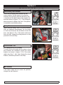
One Bar - Low Battery Voltage
This code could indicate discharged batteries,
failed batteries, or poor battery connections.
Begin by recharging the batteries and then refer
to Section 1 to check batteries and connections.
Fig 3.1.1
Fig 3.1.1
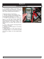
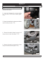
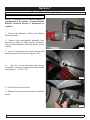
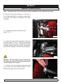
Two Bars - Left Motor Disconnected
Check that the batteries are fully charged and
in good condition; and check all cables and
connections. Check the connections to the left
motor, look for a loose or damaged connector.
Use the meter to check the resistance across the
two bottom contacts (thicker wires) on the 4-pin
motor connector as shown in (figure 3.1.1). If the
meter reads between 0 to 1.5 ohms, then replace
the controller. If none of the above corrects the
problem, replace the left motor.
Fig 3.1.2
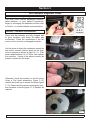
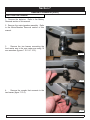
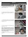
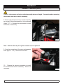
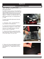
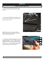
Otherwise, check the brushes on the left motor
Using a Flat head screwdriver (figure 3.1.2)
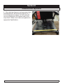
remove the brush cap to access the brush (figure
3.1.3) Ensure that they are not excessively worn,
see curvature on brush (figure 3.1.4) Replace as
required.
Fig 3.1.3
Fig 3.1.4
SUNRISE MEDICAL
PULSE 6 SERVICE MANUAL
SEPT 2011
PAGE 3.1
Section 3
VR2 Controller Diagnostics Codes (cont.)
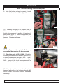
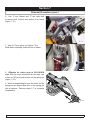
Three Bars - Left Motor Wiring Trip
Check that the batteries are fully charged and
in good condition; and check all cables and
connections. Check the connections to the left
motor, look for a loose or damaged connector.
Measure the resistance from the bottom contact
of the red thick wire on the 4-pin left motor
connector to each of the top contacts of the
connector (figure 3.2.2). Measure the resistance
from the bottom contact of the black thick wire on
the 4-pin left motor connector to each of the top
contacts of the connector. If all of the readings
are open, then replace the controller. If any of the
readings are short, then replace the left motor.
Fig 3.2.1
Test 1
Test 2
Test 3
Test 4
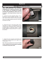
Four Bars- Right Motor Disconnected
Check that the batteries are fully charged
and in good condition; and check all cables
andconnections. Check the connections to
the right motor, look for a loose or damaged
connector.
Use the meter to check the resistance across
the two bottom contacts of the thicker wires on
the 4-pin motor connector as shown in (figure
3.3.1). If the meter reads between 0 to 1.5 ohms,
then replace the controller. If none of the above
corrects the problem, replace the right motor.
PAGE 3.2
SEPT 2011
PULSE 6 SERVICE MANUAL
Fig 3.2.2
SUNRISE MEDICAL
Section 3
VR2 Controller Diagnostics Codes (cont.)
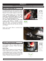
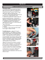
Otherwise, check the brushes on the Right motor
(figure 3.3.2). Using a Flat head screwdriver
remove the brush cap to access the brush.
Ensure that they are not excessively worn, see
curvature on brush (figure 3.2.1) Replace as
required.
Fig 3.3.1
Fig 3.3.2
Five Bars - Right Motor Wiring Trip
Check that the batteries are fully charged and
in good condition; and check all cables and
connections. Check the connections to the right
motor, look for a loose or damaged connector.
If the reading is short (resistance is less than
10 K ohms) on any of the readings, proceed to
check the 4-pin motor connector. Measure the
resistance from the bottom contact of the red
thick wire on the 4-pin right motor connector to
each of the top contacts of the connectors see
(figure 3.3.3). Measure the resistance from the
bottom contact of the black thick wire on the 4-pin
right motor connector to each the top contacts of
the connector (below right). If all of the readings
are open, then replace the controller. If any of the
readings are short, then replace the right motor.
SUNRISE MEDICAL
Fig 3.3.3
Test 1
Test 2
Test 3
Test 4
PULSE 6 SERVICE MANUAL
SEPT 2011
PAGE 3.3
Section 3
VR2 Controller Diagnostics Codes (cont.)
Six Bars - Charger Connected
The Onboard Batteries are being charged with the off-board charger. You will not be able to drive the
wheelchar until the charger is disconnected. You will have to reset the control system by switching
off the power and then powering up again. The On-Board charger has no indication that the chair
is charging, and the chair will not move until complete. If the condition still exists after the charger
has been diconnected, and the chair has been switched off and then powered up again, the Joystick
module may be defective.
Seven Bars - Possible Joystick Trip
A joystick trip is indicated. Make sure that the joystick is in the center position before switching on the
control system. Check that the batteries are fully charged and in good condition, examine the joystick
for damage. This fault can also be caused by a joystick that fails to center itself due to being dirty,
bent or broken. If this is the case, replace the joystick module.
Note: If replacing the joystick does not resolve the issue, replace the cable connecting the joystick to
the controller.
Seven Bars + Speed Profile Indicator error
Inspect the wiring between joystick module and controller. Replace the jumper or joystick module with
damaged wiring. If the problem persists replace the controller.
Eight Bars - Possible Control System Trip
Controller Fault - A control system trip is indicated. Make sure that all connections are secure. Check
that the batteries are fully charged and in good condition, and check all joystick connections and
cables. If this does not correct the problem,disconnect the power to the controller for 2 minutes, replug
in to reboot the module. If the condition still exits, then replace the controller.
PAGE 3.4
SEPT 2011
PULSE 6 SERVICE MANUAL
SUNRISE MEDICAL
Section 3
VR2 Controller Diagnostics Codes (cont.)
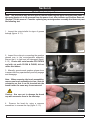
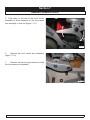
Nine Bars - Solenoid Brake Trip
The parking brakes have a bad connection. Check
the parking break and motor connections. Make
sure the control system connections are secure.
Measure the two small contacts on the four-pin
motor connector (figure 3.5.1). If both motor
connectors read approximately 60 ohms, (for
chairs prior to PLS-101619 only) then replace
the controller. Otherwise replace the motor that
does not read approximately 60 ohms.
For chairs after PLS-101619 or with serial
number prefix PLS6A, or PLS6B, it should
read ≈13.3 ohms. If both motor connections
read ≈13.3 ohms, then replace the controller.
Otherwise replace the motor that does not read
≈13.3 Ohms.
Fig 3.5.1
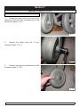
Figure 3.5.2 shows Motor in unlocked (freewheel) 9bar state.
fig. 3.5.2
Ten Bars - High Battery Voltage
An excessive voltage has been applied to the
control system. This is usually caused by a
poor battery connection. Check the battery
connections.
Battery Fault
Check that the batteries are fully charged, the
correct voltage and in good condition. Take a
voltage reading from pin 1 and pin 2 of the charger
port of the VR2 controller, see (figure 3.5.2) If the
meter reads more than 30 volts, then check the
charger. Otherwise, replace your controller.
SUNRISE MEDICAL
PULSE 6 SERVICE MANUAL
Fig .3.5.2
2
1
3
SEPT 2011
PAGE 3.5
Section 4
R-net Troubleshooting Procedures
Chair Will Not Power Up
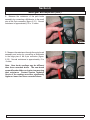
1. Check for battery voltage at the hand control
using a Multimeter. Connect the Multimeter
between the two outside pins (figure 4.1.1), pin 1
is positive (+), pin 2 is negative (-). Note: Positive
is on the right.
2
1
3
Fig. 4.1.1
2. If battery voltage is present, replace the
following components in this order:
a. Cables
b. Hand control
c. Control module. (refer to the Control Module
Replacement section of this manual.)
d. Retest as necessary.
A
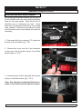
3. Verify that the buss cables are correctly mated
between the hand control and the control module
(figure 4.1.2).
Note: This connector is mated incorrectly.
The connectors are designed to visually
indicate when they are not mated correctly.
If yellow is showing between the halves (A),
push them closer together until only black is
visible. Retest as necessary.
SUNRISE MEDICAL
PULSE 6 SERVICE MANUAL
Fig. 4.1.2
SEPT 2011
PAGE 4.1
Section 4
R-net Troubleshooting Procedures (cont.)
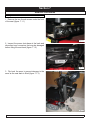
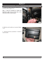
5. Disconnect the power connector from the
control module, and use a Multimeter to check
for battery voltage at the connector (figure 4.2.1).
If voltage is present, replace the control module.
Retest as necessary.
Note: The power connector is the larger 2-pin
connector between the left and right motor
cable.
6. Manually tilt the seat back and remove the
shroud from the base. Refer to Battery Removal
section of this manual.
fig 4.2.1
7. For chairs prior to PLS-100808, verify that
the circuit breaker located at the front of the
power chair is not tripped (figure 4.2.2). Reset if
it is tripped and retest.
fig. 4.2.2
8. Disconnect the batteries.
section 7.1)
PAGE 4.2
SEPT 2011
(also see Sub-
PULSE 6 SERVICE MANUAL
SUNRISE MEDICAL
Section 4
Rnet Troubleshooting Procedures (cont.)
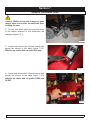
9. Verify that battery voltage is present at each
connector leading to the batteries (fig. 4.6).
fig. 4.3.1
10. If battery voltage is not present, use a
Multimeter and measure for continuity across the
fusible links connected to positive (+) terminal of
each battery (fig. 4.7). Normal resistance is less
than 1 ohm. If open, replace the defective battery
harness. Retest as necessary.
.
fig. 4.3.2
Caution: To prevent damage to the Multimeter,
ensure that the batteries are disconnected.
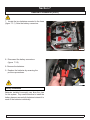
11. For chairs prior to PLS-100808, Check for
continuity across the circuit breaker (figure 4.3.3).
If Normal resistance is less than 1 ohm. If open,
replace the circuit breaker. Retest as necessary.
Note: Access to the circuit breaker terminals is
easier if the front battery is removed..
fig. 4.3.3
12. If the above tests pass, replace the wiring
harness leading from the batteries through the
circuit breaker and control module. Retest as
necessary.
.
SUNRISE MEDICAL
PULSE 6 SERVICE MANUAL
SEPT 2011
PAGE 4.3
Section 5
R-net Fault Codes
Power Chair Displays a Fault on the Hand Control or Omni
The R-Net control used on this power chair
is constantly monitoring for conditions that can
cause unsafe or erratic operation. When a fault
is displayed, refer to the fault code table in this
manual for a list of corrective actions.
Identified Module
The following identifies which module of the
control system has registered the problem.
• PM-Power Module (Control Module)
• JSM-Joystick Module/Omni Module
• ISM-Intelligent Seating/lighting Module
Trip Code
0506
PM
Module Error
Trip Text
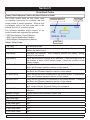
Table 1, Error Codes
Trip Text
Corrective Action
Joystick Error
Ensure that the joystick is centered upon power up. If it is centered,
replace the hand control.
Recharge the batteries. After charging, perform the Battery Testing
section of this manual.
Verify that the battery charger is not defective. Leave the chair on for a
few minutes to drain off the excess charge. Check the condition of the
battery charger.
Verify that the left motor is connected to the control module. Complete the
Motor and Gearbox Inspection section of this manual.
Verify that the right motor is connected to the control module. Complete
the Motor and Gearbox Inspection section of this manual.
Verify that the left motor is connected to the control module. Complete the
Motor and Gearbox Inspection section of this manual.
Verify that the right motor is connected to the control module. Complete
the Motor and Gearbox Inspection section of this manual.
Cycle power. Check all cable connections. If this does not correct the
fault, contact Sunrise Technical Service for assistance.
Calibrate the joystick. If the error is still present, the hand control may be
defective.
A latch function has exceeded it preset time.
N/A
N/A
N/A
N/A
N/A
N/A
N/A
Low Battery
High Battery
M1 Brake Error
M2 Brake Error
M1 Motor Error
M2 Motor Error
Inhibit Active
Jstick Cal Error
Latched Timeout
Brake Lamp Short
Left Lamp Short
Right Lamp Short
L Ind Lamp Short
R Ind Lamp Short
L Ind Lamp Failed
R Ind Lamp Failed
SUNRISE MEDICAL
PULSE 6 SERVICE MANUAL
SEPT 2011
PAGE 5.1
Section 5
R-net Fault Codes cont.
Table 1, Error Codes cont.
Over-current
Overtemp. (Acts)
Overtemp. (Lamps)
DIME Error
Memory Error
PM Memory Error
Bad Cable
Bad Settings
Module Error
System Error
SID Detached
User Switch Detached
Gone to Sleep
Charging
PAGE 5.2
SEPT 2011
This fault occurs when the limits of an actuator circuit is exceeded.
Perform Tilt Will Not Operate troubleshooting section of this manual to test
the end of travel limit switches.
This error indicates that the Intelligent Seating Module (ISM) has become
excessively warm. Note: An ISM is only required when there are more
than 2 actuators and may not be mounted on this power chair. Allow the
unit to cool. If the error repeats, the actuator may be defective or over
loaded.
Note: This fault can only occur if an Intelligent Seating Module is used on
this power chair and connected to external lights.
This error indicated that one or more of the modules are not compatible.
Remove the last module installed and retest. Recycle the power. Contact
Sunrise Technical Service for assistance.
Recycle the power. Verify that the cables are correctly mated. If a module
has been replaced recently, that module may be defective. Contact
Sunrise Technical Service for assistance.
Recycle the power. Verify that the cables are correctly mated. If a module
has been replaced recently, that module may be defective. Contact
Sunrise Technical Service for assistance.
Inspect and replace the defective cable(s).
Verify that the programming agrees with the installed equipment. If
all settings are correct, the control module may be defective. Contact
Sunrise Technical Service for assistance.
Recycle the power. Verify that the cables are correctly mated. If a module
has been replaced recently, that module may be defective. Contact
Sunrise Technical Service for assistance.
Recycle the power. Verify that the cables are correctly mated. If a module
has been replaced recently, that module may be defective. Contact
Sunrise Technical Service for assistance.
The Omni has detected that a specialty control has become disconnected.
Recheck all cables. If the error is still present, replace the specialty
control.
Indicates that a user switch has become disconnected. Reconnect the
switch.
The predetermined sleep time has been exceeded due to inactivity by the
user.
This indication is present when the battery charger is connected. There
may also be an error in the control module. Contact Sunrise Technical
Service for assistance.
PULSE 6 SERVICE MANUAL
SUNRISE MEDICAL
Section 5
R-net Fault Codes cont.
Note: On hand controls that contain LED battery gauges, they will display the fault code by
illuminating various LEDs . Refer to the Corrective Action column for a list of items to check
for each fault.
Bar Indication
Corrective Action
The battery needs charging or there is a bad connection
to the battery. Check the connections to the battery. If the
connections are good, recharge the battery.
Verify that the left motor is connected to the control
module. Complete the Motor and Gearbox Inspection
section of this manual.
The left motor has a short circuit to a battery connection.
Contact Sunrise Medical Technical Service for
assistance.
The right motor has a bad connection. Complete the Motor
and Gearbox Inspection section of this manual.
The right motor has a short circuit to a battery connection.
Contact Sunrise Medical Technical Service for
assistance.
The wheelchair is being prevented from driving by an
external signal. Verify that the battery charger is not
connected. Contact Sunrise Medical Technical Service
for assistance.
Ensure that the joystick is centered upon power up. If it is
centered, replace the hand control, and or cable.
A control system fault is indicated. Make sure that
all connections are secure. Contact Sunrise Medical
Technical Service for assistance.
The parking brakes have a bad connection. Complete the
Motor and Gearbox Inspection section of this manual.
Verify that the battery charger is not defective. Leave the
chair on for a few minutes to drain off the excess charge.
Check the condition of the battery charger.
A communication fault is indicated. Make sure that joystick
cable is securely connected and not damaged.
An Actuator trip is indicated. If more than one actuator is
fitted, check which actuator is working correctly. Check the
actuator wiring.
SUNRISE MEDICAL
PULSE 6 SERVICE MANUAL
SEPT 2011
PAGE 5.3
Section 5
R-net Fault Codes cont.
Example of R-10 Fault Isolation
1. In this example, one of the right motor being
disconnected (figure.5.4.1). The hand control
displays the fault and the power chair will not
operate.
2. To troubleshoot this problem, refer to Table 1,
Error Codes.
3. From this error we see that the problem is
being recorded in the PM (Control Module).
4. The hand control tells us that motor 2 (M2) has
the error and it is with the brake circuit. Motor 2
is the right motor.
5. Table 1 informs us to, “Verify that the right motor
is connected to the control module. Complete the
Motor and Gearbox Inspection section of this
manual.”
6. The next step is to complete the Motor and
Gearbox Inspection section of this manual and
retest.
fig. 5.4.1
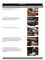
Power Chair Will Not Drive Full Speed
An external micro-switch is mounted next to the actuator in the rear of the tilt system. This micro-switch
is open when the tilt is lowered. The opening of this micro-switch blocks a signal from being sent to
the control module through the 6-pin connector located on the back of the tilt. The absence of this
signal informs the control module that the tilt is less than 20 degrees and that maximum speed should
be used. If the tilt is more than 20 degrees, the switches closes and invokes “creep” speed. Creep
speed is a predetermined speed programmed at time of manufacture. Creep is indicated by a “turtle”
on either the hand control or Omni.
1. “Creep” speed as indicated by the turtle on the
hand control ("A" figure 5.4.2).
A
2. Tilt the seating system to the rear.
fig. 5.4.2
PAGE 5.4
SEPT 2011
PULSE 6 SERVICE MANUAL
SUNRISE MEDICAL
Section 5
R-net Fault Codes cont.
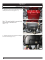
3. Locate the creep micro-switch mounted at the
rear of the actuator "A" (figure 5.5.1).
Note: The creep micro-switch may be seen from
the top of the seating system on the right rear of
the actuator. It may be necessary to remove the
seat pan to access the switch.
4. Manually operate the creep micro-switch while
observing the hand control or Omni for the turtle
symbol to go on and go off with the micro-switch
operation. If the symbol changes, the problem
is in the programming. Contact Sunrise Medical
Technical Service for assistance. If the symbol
does not change, proceed to step 5.
5. Lower the tilt system.
6. Locate the 6-pin connector "B" at the rear of
the tilt unit (figure 5.5.2).
7. Disconnect the connector leading to the control
module.
A
fig. 5.5.1
B
8.
Test the micro-switch wiring by performing
the following test.
a.
Ensure that the seat is in the full down
position.
b.
Use Multimeter and measure continuity
between the indicated pins below on the 6-pin
connector mounted on the tilt. When down the
indication should be open (figure 5.5.3).
c.
If it is closed, replace the micro-switch
assembly. Refer to Tilt Actuator and Micro-Switch
Removal section of this manual.
d.
Retest as necessary.
fig. 5.5.2
9.
If the above test passes, replace in this
order:
a.
Cable leading from tilt to control module.
b.
Control module
10. Retest as necessary
Open
fig. 5.5.3
SUNRISE MEDICAL
PULSE 6 SERVICE MANUAL
SEPT 2011
PAGE 5.5
Section 5
R-net Fault Codes cont.
Power Chair Will Not Drive in Creep Speed When Tilted
An external micro-switch is mounted next to the actuator in the rear of the tilt system. This micro-switch
is open when the tilt is lowered. The opening of this micro-switch blocks a signal from being sent to
the control module through the 6-pin connector located on the back of the tilt. The absence of this
signal informs the control module that the tilt is less than 20 degrees and that maximum speed should
be used. If the tilt is more than 20 degrees, the switches closes and invokes “creep” speed. Creep
speed is a predetermined speed programmed at time of manufacture. Creep is indicated by a “turtle”
on either the hand control or Omni.
1. Tilt the seat all the way back and observe the
hand control or Omni to see if the turtle symbol
"A" is displayed.
2. If the turtle is displayed (figure 5.6.1), contact
Sunrise Technical Service for assistance. The
programming for the power chair is incorrectly
set.
A
3. Use the hand control and tilt the seating system
beyond 20 degrees.
fig. 5.6.1
4. Locate the 6-pin connector "B" on the rear of
the tilt (figure 5.6.2).
5. Disconnect the connector leading to the control
module
6. Test micro-switch with the following test.
a. Ensure that the tilt is beyond 20 degrees tilt.
b.
Use Multimeter and measure continuity
between the indicated pins below on the 6-pin
connector mounted on the tilt. When seat is tilted
the indication should be closed (figure 5.6.3).
c. If it is open, replace the micro-switch assembly.
Refer to Tilt Actuator and Micro-Switch Removal
section 7 of this manual.
d. Retest as necessary.
B
fig. 5.6.2
Closed
fig. 5.6.3
PAGE 5.6
SEPT 2011
PULSE 6 SERVICE MANUAL
SUNRISE MEDICAL
Section 5
R-net Fault Codes cont.
Tilt Will Not Operate
The tilt actuator used in the tilt system receives
power through a 6-pin connector located at the
rear of the tilt See "B" (Figure 5.6.2). The actuator
also contains micro-switches that open at the
end of their stroke to prevent stressing of the tilt
system. Around these micro switches are diodes
that allow reverse power to flow to the actuator
when reversing direction.
1. Select tilt on the hand control (figure. 5.7.1).
Operate the joystick and listen closely to the
control module for a click. This click indicates
that the control module is closing the power relay
inside and supplying power to the tilt actuator.
If no click is heard, replace the control module.
Refer to Control Module Replacement section this
manual. Retest as necessary. If click is heard
proceed to step 3.
2. Verify that tilt is selected on the hand control.
Operate the joystick and listen closely to the tilt
actuator. If the actuator appears to be running
but the tilt is not moving, replace the tilt actuator.
Refer to Tilt Actuator and Micro-Switch Removal
section of this manual. Retest as necessary.
3. Locate the 6-pin connector on the rear of the tilt
See "B" (figure 5.6.2 previous page).
4. Disconnect the 6-pin cable leading to the
control module.
fig. 5.7.1
5. Select tilt on the hand control and place a
rubber band around the joystick to hold it displaced
(figure 5.7.2).
fig. 5.7.2
SUNRISE MEDICAL
PULSE 6 SERVICE MANUAL
SEPT 2011
PAGE 5.7
Section 5
R-net Fault Codes cont.
Warning: Use caution in the next step. Do not short the leads of the Multimeter together
or damage may occur to the control module.
6. At the 6-pin connector on the cable leading to
the control module, verify that battery voltage is
present between the indicated pins (figure 5.8.1).
Note: The polarity of the voltage is not important
since it is reverses when the opposite direction is
selected.
7. If voltage is not present, replace the cable
leading to the control module. If this does not
solve the problem, replace the control module.
Refer to Control Module Removal section of this
manual. Retest as necessary.
fig. 5.8.1
8. At the 6 pin connector "B" (figure 5.8.2) on
the rear of the tilt, check continuity between the
indicated pins (fig. 5.8.3).
B
fig. 5.8.2
to
1Voltage
to 3 ohms
the actuator
fig. 5.8.3
PAGE 5.8
SEPT 2011
PULSE 6 SERVICE MANUAL
SUNRISE MEDICAL
Section 5
R-net Fault Codes cont.
Note: Since the tilt actuator will not operate,
it is only possible to check for one condition.
Pick the condition below that best describes
the position of the tilt system.
9. Example 1, the tilt is in mid-stroke. The value
recorded is the resistance through the actuator
motor windings (Figure 5.9.1). If this reading is
not correct, replace the tilt actuator and retest.
1 to 3 ohms
fig. 5.9.1
Note: The value recorded in one direction is
the forward resistance through a diode and
will vary with the type of Multimeter used.
This value is not important, as long as there
is continuity in one direction only. This value
may even be high. The value recorded in the
other direction is across the open contact of
the end of stroke micro-switch and should be
open.
10. Example 2, the tilt is in the full down position
(Figure 5.9.2). If the readings are not correct,
replace the tilt actuator. Refer to Tilt Actuator
and Micro-Switch Removal section this manual.
Retest as necessary.
Note: The value recorded in one direction is
the forward resistance through a diode and
will vary with the type of Multimeter used.
This value is not important, as long as there
is continuity in one direction only. This value
may even be high. The value recorded in the
other direction is across the open contact of
the end of stroke micro-switch and should be
open.
11. Example 3, the tilt is in the full up position
(figure 5.9.3). If the readings are not correct,
replace the tilt actuator. Refer to Tilt Actuator
and Micro-Switch Removal section this manual.
Retest as necessary.
SUNRISE MEDICAL
PULSE 6 SERVICE MANUAL
Positive probe here
Negative probe here
Continuity between pins
Negative probe here
Positive probe here
Open between pins
*SEE NOTE*
fig. 5.9.2
Positive probe here
Negative probe here
Open between pins
Negative probe here
Positive probe here
Continuity between pins
*SEE NOTE*
fig. 5.9.3
SEPT 2011
PAGE 5.9
Section 5
R-net Fault Codes cont.
Battery Testing
The Pulse power chair uses two (2) group-22 batteries connected in series. The circuit is protected
by a circuit breaker located under the shroud near the front of the power chair and a non-serviceable
fusible link in each battery harness. Prior to performing any test, the battery terminals should be clean
and tight. Refer to Battery Removal section of this manual.
1. Check for initial battery voltage at the joystick
using the battery charger connector. Connect the
Multimeter to the two outside pins (figure 5.10.1).
Pin 1 is positive (+) and pin 2 is negative (-). Fully
charged batteries are typically 25.6 VDC for the
pair, or 12.8 VDC each. Discharged batteries are
24 VDC or less for the pair.
Note: Voltage greater than 26 to 28 VDC
indicates that the batteries are either overcharged, or the batteries have just been
disconnected from the battery charger and
contain a surface charge. If the batteries
are not freshly charged and the voltage is
excessive, inspect the battery charger for
correct operation.
2. Load test the batteries using either a commercial
load tester or the following procedure. To use the
power chair’s motors as a load, complete the
following steps:
Warning: Failure to disengage the gearbox in
the next step can cause unexpected operation
of the power chair.
a.
Disengage the motor/gearbox so the motors
can run in freewheel (figure. 5.10.2).
b.
Connect the Multimeter to the joystick and
record the voltage (figure. 5.10.3). If the voltage
indicates a surface charge, run the motors for
a few minutes to dissipate the surface charge.
Note: in this example, a small surface charge is
present.
c.
After the voltage has stabilized, record the
voltage. Typical value for a fully charged pair of
batteries is 25.6 VDC (12.8 VDC each).
fig. 5.10.1
fig. 5.10.2
fig. 5.10.3
PAGE 5.10
SEPT 2011
PULSE 6 SERVICE MANUAL
SUNRISE MEDICAL
Section 5
R-net Fault Codes cont.
d. Operate the power chair at high speed by
operating the joystick in a high-speed profile. The
motors put approximately a 5 to 10 amp load on
the batteries.
e. Continue to operate the motors for 60 seconds.
(figure 5.11.1) Record the readings and compare
them to following:
i. During the first 5 seconds, normal voltage
drop is approximately .5 to .6 VDC.
ii. During the remaining portion of the 60
seconds, the voltage should stabilize, dropping
no more than an additional .1 to .2 VDC.
iii. At the end of the 60 seconds, release the
joystick.
fig. 5.11.1
f. At the end of a 5 minute rest, note the voltage
recorded on the Multimeter. Normal indication at
the end of a 5 minute rest is typically the starting
voltage, or no more than .1 VDC less.
Notes:
•
A rapid drop of approximately 1.5 or more during the first 5 seconds indicates a shorted
cell in one or both of the batteries. The battery terminals should be checked to ensure that they
are tight and clean, and then the test should be repeated. If the terminals are tight, the batteries
should be replaced. Refer to Battery Removal section of this manual.
•
A slow drop of more than .8 volts during the first few seconds indicates a weakened pair
of batteries. Evaluate the age of the batteries and the use they have received, and consider
replacing them.
•
If the voltage does not return to .1 VDC of the starting voltage at the end of the 5 minute
test, evaluate the age of the batteries and the use they have received, and consider replacing
them.
SUNRISE MEDICAL
PULSE 6 SERVICE MANUAL
SEPT 2011
PAGE 5.11
Section 5
R-net Fault Codes cont.
3. The individual voltage of each battery may
also be checked using a Multimeter. Connect the
Multimeter to the battery connector (figure 5.12.1).
Note: Refer to Battery Removal (Section 7).
Compare the values to the following.
a. 12.8 VDC indicates a fully charged battery.
b. The battery readings should be similar. Newer
batteries typically read within .1 to .2 VDC.
c. 13 VDC or more indicates an overcharged
battery, or one that has a surface charge from
being recently removed from the charger. Verify
correct operation of the battery charger if the
batteries have not recently been removed from
charge.
d. 11.9 to 12 VDC indicates a discharged battery.
Recharge as necessary.
e. Less than 11.9 VDC indicates an excessively
discharged battery.
f. Values larger than 13 VDC indicate either an
overcharged battery or one that has just been
removed from charge, as in the example (figure
5.12.1)
PAGE 5.12
SEPT 2011
PULSE 6 SERVICE MANUAL
fig. 5.12.1
SUNRISE MEDICAL
Section 6
Motor/Gearbox Inspection
Note: This procedure may be done with or without removing the motor from the power chair. If
the motor/gearbox is to be removed from the power chair, refer to Motor and Gearbox Removal,
(Section7) of this manual. Consider replacing any motor/gearbox assembly that does not pass
the following test.
1. Inspect the output shafts for signs of grease
leakage (figure. 6.1.1).
fig. 6.1.1
2. Inspect the cotter pin connecting the gearbox
release arm to the motor/gearbox assembly.
Ensure that it is tight and not damaged (figure.
6.1.2). Chairs after serial number PLS-101619
and with s/n prefix PLS6A & PLS6B, did not
utilize this feature.
3. Manually operate each gearbox release lever
to ensure that they operate easily and fully engage
and disengage
Note: When removing the brush assemblies,
remove one brush assembly at a time. Note its
orientation so that it can be inserted into the
brush holder the same way it was removed.
fig. 6.1.2
Caution: Use care not to damage the brush
cap with excessive force in the next step.
4. Remove the brush by using a common
screwdriver to unscrew the cap (figure. 6.1.3).
fig. 6.1.3
SUNRISE MEDICAL
PULSE 6 SERVICE MANUAL
SEPT 2011
PAGE 6.1
Section 6
Motor/gear Box Inspection (cont.)
Note: When replacing brush assemblies,
always replace both motors. Run-in the brush
assemblies prior to delivering the power chair
to the customer by releasing the gearbox
assembly and operating the motor for 20 to
30 minutes, alternating between forward and
reverse.
5. Inspect the brush assembly (figure. 6.2.1).
Replace any brush assembly less than ¼ inch
long. Ensure that the lead to the brush and spring
has not over heated and that the ends of the brush
are sharp and clean.
fig. 6.2.1
6. Inspect the motor’s commutator (figure 6.2.2).
Verify that it is clean, not overheated, and does
not show signs of excessive arcing. Normal color
is bright copper to dull brown copper. Contact
Sunrise Medical Technical Service if in doubt of
its condition.
fig. 6.2.2
7. Inspect the motor connector at both the motor
end and the control module end for signs of over
heating (figure. 6.2.3).
Note: Disconnect the motor connector from the
control module if the motor/gearbox assembly
is mounted in the power chair.
fig. 6.2.3
PAGE 6.2
SEPT 2011
PULSE 6 SERVICE MANUAL
SUNRISE MEDICAL
Section 6
Motor/gear Box Inspection (cont.)
8. Measure the resistance of the park brake
assembly by connecting a Multimeter to the small
pins of the 4-pin connector (figure. 6.3.1). Normal
resistance is approximately 12 to 15 ohms.
fig. 6.3.1
9. Measure the resistance through the motor brush
assembly and motor by connecting a Multimeter
to the large pins of the 4-pin connector (figure.
6.3.2). Normal resistance is approximately .5 to
.9 ohms.
Note: New brush readings may be different
than those recorded above. The new brush
assemblies should be run-in prior to measuring
their resistance. Contact Sunrise Technical
Service if the readings are either significantly
higher or lower than those recorded above.
SUNRISE MEDICAL
PULSE 6 SERVICE MANUAL
fig. 6.3.2
SEPT 2011
PAGE 6.3
Section 7
Removal Procedures
Battery Removal
1. Remove the two thumb screws under the front
of the seat (figure. 7.1.1)
fig. 7.1.1
2. Inspect the power chair base at the back and
disconnect any connectors that may be damaged
before tilting the seat back (figure 7.1.2).
fig. 7.1.2
3. Flip back the arms to prevent damage to the
arms as the seat back is tilted (figure 7.1.3).
fig. 7.1.3
SUNRISE MEDICAL
PULSE 6 SERVICE MANUAL
SEPT 2011
PAGE 7.1
Section 7
Removal Procedures (cont)
Caution: While not required, it may be a good
idea to place a box under the seat back prior
to tilting the seat.
4. Tilt the seat back while ensuring that none
of the cables attached to the electronics are
damaged (figure 7.2.1).
fig. 7.2.1
5. Locate and remove the 6 plastic inserts that
secure the shroud to the base (figure 7.2.2).
Effective on chairs with s/n prefix PLS only.
fig. 7.2.2
6. Locate and remove the 4 thumb screws that
secure the shroud to the base (figure 7.2.3)
effective on chairs with s/n prefix PLS6A and
PLS6B
fig. 7.2.3
PAGE 7.2
SEPT 2011
PULSE 6 SERVICE MANUAL
SUNRISE MEDICAL
Section 7
Removal Procedures (cont.)
7. Locate the two batteries mounted in the base
(figure 7.3.1) Note the battery connectors.
fig. 7.3.1
8. Disconnect the battery connectors
(figure 7.3.2).
8. Remove the batteries.
9. Replace the batteries by reversing the
previous procedures.
fig. 7.3.2
Battery Installation
Batteries installed incorrectly can blow the fuse
for this system. Pay careful attention to install the
battery harness across both batteries instead of to
each of the batteries individually.
SUNRISE MEDICAL
PULSE 6 SERVICE MANUAL
SEPT 2011
PAGE 7.3
Section 7
Removal Procedures (cont.)
Motor and Gearbox Removal
1. Remove the batteries. Refer to the Battery
Removal in this section.
2. Locate and disengage the connector leading
from the motor to the control module (figure..
7.4.1).
fig. 7.4.1
3. Elevate the wheelchair by placing wood blocks
under the battery box (fig. 7.4.2).
fig. 7.4.2
4. Remove the wheel’s hubcap by prying it off
using a common screw drive (figure. 7.4.3) .
fig. 7.4.3
5. Remove the wheel by removing the 4 bolts
using a 6 mm Allen wrench (figure. 7.4.4).
fig. 7.4.4
PAGE 7.4
SEPT 2011
PULSE 6 SERVICE MANUAL
SUNRISE MEDICAL
Section 7
Removal Procedures (cont.)
6. Use 17 mm Rachet and 17 mm open end
to remove bolt ,locknut and washer from frame
(figure 7.5.1).
fig. 7.5.1
7. View of 17mm nylock nut (figure 7.5.2).
Slide Motor Assembly down and out of frame.
fig. 7.5.2
8. Effective for chairs prior to PLS-101619
only. With the motor removed from the chair, use
a 3mm or 1/8" pin punch to drive out the spring pin
(figure 7.5.3).
9. When re-assembling be sure the holes for the
spring pin are aligned and drive in the spring pin
with a hammer. Reverse steps 1-7 to complete
re-assembly.
fig. 7.5.3
SUNRISE MEDICAL
PULSE 6 SERVICE MANUAL
SEPT 2011
PAGE 7.5
Section 7
Motor Removal for chairs after S/N PLS-101919 and s/n prefix PLS6A &PLS6B
1. Remove 4 bolts from wheel and elevate
frame as shown. (Figure 7.6.1)
fig. 7.6.1
2. Using a 17mm socket and open end
wrench, remove front suspension bolt and nut
combination shown in (figure 7.6.2)
fig. 7.6.2
3. Remove motor from chair (figure 7.6.3)
fig. 7.6.3
4. Remove the 5 bolts from the motor plate
assembly with a 5mm Hex Key (figure 7.6.4)
Note: Upon re-assembly, make sure to re-tighten
the motor plate back to 40 inch/pounds of
torque.
fig. 7.6.4
5. Final motor removal step requires
disconnecting Motor connection from control
module and cutting the Ty-wrap (Figure 7.6.5).
Both parts should be re-attached when motor is
re-installed..
fig. 7.6.5
PAGE 7.6
SEPT 2011
PULSE 6 SERVICE MANUAL
SUNRISE MEDICAL
Section 7
Removal Procedures (cont.)
Control Module Removal
1. Remove the rear cover by lifting the two quick
release pins from the cover (figure. 7.7.1).
fig. 7.7.1
Note: The control module is mounted under
the rear cover of the power chair
(figure 7.7.2).
fig. 7.7.2
2. Carefully disconnect the connectors leading to
the control module (figure 7.7.3)
fig. 7.7.3
SUNRISE MEDICAL
PULSE 6 SERVICE MANUAL
SEPT 2011
PAGE 7.7
Section 7
Removal Procedures (cont.)
3. Loosen the control module by loosening two 3
mm Allen screws (figure 7.8.1).
Note: It may be necessary to remove the
batteries to gain access to the nuts on the
other side of the control module.
fig. 7.8.1
4. Slide the control module up to remove it (figure.
7.8.2).
5. Reverse the above procedures to install the
control module
fig. 7.8.2
PAGE 7.8
SEPT 2011
PULSE 6 SERVICE MANUAL
SUNRISE MEDICAL
Section 7
Removal Procedures (cont.)
Shock Removal
NOTE: The shocks used in this power base are
pre-adjusted at the factory. Contact Sunrise
Medical Technical Service if adjustment is
required.
1. Remove the batteries. Refer to the Battery
Removal section.
2. Remove the motor/gearbox assembly from
the side on which you are removing the shock.
Refer to Motor/Gearbox Removal section of this
manual.
fig. 7.9.1
3. Use a 17 mm wrench and remove the top bolt
securing the shock to the base (figure 7.9.1).
4.
Use two 19 mm wrenches and remove
the bottom nut and bolt securing the shock to the
base (figures . 7.9.2 & 7.9.3).
fig. 7.9.2
5. Lift the shock from the base.
6. Reverse the previous procedures to install the
shock.
fig. 7.9.3
SUNRISE MEDICAL
PULSE 6 SERVICE MANUAL
SEPT 2011
PAGE 7.9
Section 7
Removal Procedures (cont.)
Front Caster Arm Removal
1. Remove the batteries. Refer to the Battery
Removal section of this manual.
2. Remove the motor/gearbox assembly. Refer
to the Motor/Gearbox Removal section of this
manual.
3.
Remove the two braces connecting the
front caster arm to the rear caster arm using 19
mm wrenches (figures 7.10.1 & 7.10.2).
fig. 7.10.1
fig. 7.10.2
4.
Remove the coupler that connects to the
two braces (figure 7.10.3).
fig. 7.10.3
PAGE 7.10
SEPT 2011
PULSE 6 SERVICE MANUAL
SUNRISE MEDICAL
Section 7
Removal Procedures (cont.)
5. Push down on the rear of the motor mount
assembly to allow clearance for the front caster
arm assembly to slide out (figure 7.11.1).
fig. 7.11.1
6.
Remove the front caster arm assembly.
(figure 7.11.2)
7.
Reverse the previous procedures to install
the front caster arm assembly.
fig. 7.11.2
SUNRISE MEDICAL
PULSE 6 SERVICE MANUAL
SEPT 2011
PAGE 7.11
Section 7
Removal Procedures (cont.)
Rear Caster Arm Removal
1. Remove the batteries. Refer to the Battery
Removal section of this manual.
2. Remove the two braces connecting the front
caster arm to the rear caster arm using 19 mm
wrenches. (figure 7.12.1 & 7.12.2)
fig. 7.12.1
3. Remove the rear caster arm assembly (figure
7.12.3).
fig. 7.12.2
4. Reverse the previous procedures to install the
rear caster arm assembly
fig. 7.12.3
PAGE 7.12
SEPT 2011
PULSE 6 SERVICE MANUAL
SUNRISE MEDICAL
Section 7
Removal Procedures (cont.)
Front or Rear Caster Fork Removal
1. Elevate the caster fork to be removed by
placing wood blocks under the battery box of the
power chair (figure 7.13.1).
fig. 7.13.1
2. Remove the plastic cap on the caster arm
assembly using a common screwdriver (fig.
7.13.2).
fig. 7.13.2
3. Hold the caster steady with one hand while
removing the caster fork nut with a 19 mm socket
wrench (fig. 7.13.3).
4. Remove the caster fork from the caster arm
assembly (fig. 7.13.4)
fig. 7.13.3
Note: If either of the bearings needs to be
replaced, it may be necessary to use a bearing
puller on the lower bearing to separate it from
the fork stem, and a brass drift to drive out the
upper or lower bearings from the caster arm
assembly if they are stuck.
5. Reverse the previous procedures to install the
caster fork.
fig. 7.13.4
SUNRISE MEDICAL
PULSE 6 SERVICE MANUAL
SEPT 2011
PAGE 7.13
Section 7
Removal Procedures (cont.)
Caster Removal
1.
Elevate the caster fork to be removed by
placing wood blocks under the battery box of the
power chair (figure 7.14.1).
fig. 7.14.1
2.
Remove the caster using two 13 mm
wrenches (figure 7.14.2).
fig. 7.14.2
3.
Reverse the previous procedures to install
the caster (figure 7.14.3).
fig. 7.14.3
PAGE 7.14
SEPT 2011
PULSE 6 SERVICE MANUAL
SUNRISE MEDICAL
Section 7
Removal Procedures (cont.)
Tilt Actuator and Micro-Switch Removal
The following procedures describe the removal of
the tilt actuator and/or the micro-switch assembly
used for the creep speed. Read the full set of
directions prior to performing the task. Some
steps may be eliminated if both items do not need
to be replaced. Reverse the procedures to install
the tilt actuator and/or micro-switch and retest as
necessary.
A
1. Disconnect the 6-pin connector "A" located on
the rear of the tilt system (fig. 7.38).
fig. 7.15.1
2. Remove the cover over the 6 pin connector
on the rear of the tilt system using a 3 mm Allen
wrench (figure 7.15.2).
fig. 7.15.2
3. Locate the micro-switch assembly and remove
using a 3 mm Allen wrench (fig. 7.15.3).
Note: this step may be eliminated if the microswitch is to be disconnected and left in place.
fig. 7.15.3
SUNRISE MEDICAL
PULSE 6 SERVICE MANUAL
SEPT 2011
PAGE 7.15
Section 7
Removal Procedures (cont.)
Note: Complete step 4 only if the micro-switch assembly is to be replaced separately.
4. Reconnect the 6-pin connector on the rear of
the tilt and partially tilt the seating system back
to expose the actuator. Disconnect the 6-pin
connector
5. Locate the tilt actuator under the seat
(figure 7.16.1).
fig. 7.16.1
6. Locate the micro-switch assembly at the rear
of the tilt (figure 7.16.2). Note the connections
leading to the micro-switch. Separate and label
the wires leading to the micro-switch. Reverse the
procedures to replace it and retest as necessary.
fig. 7.16.2
Warning: The tilt system is free to fall during
the next step. Secure the seating system prior
to removing the tilt actuator.
7. Use two 13 mm wrenches and remove the
nuts at both ends of the actuator (figure 7.16.3).
Remove both pins from the tilt actuator.
fig. 7.16.3
PAGE 7.16
SEPT 2011
PULSE 6 SERVICE MANUAL
SUNRISE MEDICAL
Section 7
Removal Procedures (cont.)
Caution: the actuator and micro-switch assembly wires are fragile. Use caution when removing
the actuator and micro-switch assembly.
8. Remove the actuator and micro-switch assembly
as one part if the entire assembly is to be replaced
(figure 7.17.1). Reverse the procedures to install
and retest as necessary.
fig. 7.17.1
Note: Perform this step if only the actuator is to be replaced.
9. Note the connections of the wires and separate
them (figure 7.17.2). Remove the actuator.
10.
Reverse the previous procedure to install
the actuator/micro-switch assembly. Retest as
necessary.
SUNRISE MEDICAL
PULSE 6 SERVICE MANUAL
fig. 7.17.2
SEPT 2011
PAGE 7.17
Section 8
Seat/Back Width adjustment
ASAP II Seating 16” - 20” wide is shown.
(NOTE: The same procedure is used for 18”- 22”
wide seating system)
The ASAP II seating system is fully adjustable to
allow changes from 16” to 20” or 18” – 22”. This
requires a frame weldment and seat pan plates
adjust for seat growth. The pictures shown in
(figure 8.1.1) shows a 20” wide seat width . This
detail shows how easy it is to change back to
16” wide.
A
To make seating width adjustments follow the
following steps:
1. Have 3mm – 4mm – and 5mm Allen Hex
keys available for the adjustments.
fig. 8.1.1
2. Loosen (do not remove) the front M8 Button
Head Cap bolt "A" (figure 8.1.1). with a 4mm
Hex key, or a T-handle Hex key so that the
plates can slide for adjustment.
3. Using a 3mm Hex key, remove the socket
head cap screws (figure 8.1.2) that attach the
left and right wings to the seat frame.
fig. 8.1.2
4. Remove the 5mm socket head bolts with a
Hex key that are used to hold bottom seat in
place (figure 8.1.3) – totally remove out of its
position.
fig. 8.1.3
SUNRISE MEDICAL
PULSE 6 SERVICE MANUAL
SEPT 2011
PAGE 8.1
Section 8
Seat/Back Width adjustment
5. Remove the nut, and bolt that secures the
rear towel bar using a 4mm Hex Key and a 13
mm open end wrench or ratchet as shown in
(figure 8.2.1).
fig. 8.2.1
6. Loosen Back bracket on the chair to allow for
changes to the seat width. (figure 8.2.2).
NOTE: it is recommended to use the back width
to accommodate the user, for example – so 16
with 16 wide – 18 with 18” wide.
If, however there is a ½ “ adjustment that
is needed, the brackets shown in (figure
8.2.2) show that a ½” change equals a 1”
accomadation to the user .
fig. 8.2.2
7. Using a 5mm Hex Key and either a 13mm
open end wrench or ratchet., Remove the nuts
and bolts from the back bracket attached to the
back cane assembly.
fig. 8.2.3
PAGE 8.2
SEPT 2011
PULSE 6 SERVICE MANUAL
SUNRISE MEDICAL
Section 8
Seat/Back width adjustment
8. After checking alignment and symmetry of the
final adjustments, and measuring (figure 8.3.1)
the final adjustment change, the nuts and bolts
can be re-tightened in the reverse order of the
steps listed. Make sure all bolts are tightened to
appropriate Specifications.
SUNRISE MEDICAL
PULSE 6 SERVICE MANUAL
SEPT 2011
PAGE 8.3
Section 8
Legrest adjustment
1. To perform a Legrest adjustment (figure
8.4.1) the following tools are required: A 5mm
Hex Key, and a 13mm open end wrench and/or
ratchet.
fig. 8.4.1
2 Loosen all 3 sets of bolts/nuts as shown in
(figure 8.4.2) and (figure 8.4.3) using the 5mm
hex key and 13mm open-end wrench or ratchet.
fig. 8.4.2
3. There are 5 sets of holes as seen from the
front bars and 6 sets of holes as seen on on
(figure 8.4.4) where bolts can go through to give
adjustability of up to 6 inches from top to bottom.
To extend the front arms further, simply loosen
5mm size SHCS screws and move the bars
further forward, then retighten.
fig. 8.4.3
4. Once desired height is achieved, Reset
placement of bolts then tighten with 5mm Hex
key and 13mm wrench. Tighten to 40 in/lbs of
torque.
fig. 8.4.4
PAGE 8.4
SEPT 2011
PULSE 6 SERVICE MANUAL
SUNRISE MEDICAL
Section 8
Back-rest Angle Adjustment
1 Make sure you have the right tools- 5mm
Hex Key, and 13mm open end wrench and/or
ratchet.
A
2. Loosen the 2 BHCS bolts "A" (figure 8.5.1)
with a 5mm Hex key and use 13mm open end
Wrench for the nuts "B".
B
fig. 8.5.1
Note: Take care not to lose the saddles, or
plastic washers between Bracket and seat rail
while performing the next step.
-4°
3. To make a small angle change to one of four
possible settings, (-4°, 0, 4°, 8°) pull bolt out and
change the position of the front edge bracket.
(figure 8.5.2) Then re-attach the nut and tighten
bolt into place. make sure plastic saddles and
washers are in place behind the part.
0°
4°
8°
fig. 8.5.2
SUNRISE MEDICAL
PULSE 6 SERVICE MANUAL
SEPT 2011
PAGE 8.5
Section 8
Powered elevating or articulating legrest
VR2/R-Net Control
The actuator buttons can operate any factory
approved actuator. Operation is dependent on
what options are fitted to your wheelchair. To
operate the legrests, seat tilt, seat lift or back
rest recline follow the following steps
1. Push one of the actuator buttons that has the
seat icon on it to select actuator mode
2 Operate the joystick left or right to select the
actuator required (actuator 1 or actuator 2).
Selection is indicated via the lighting of the red
LED adjacent to the desired actuator button.
3. Operate the joystick in the forward or
rearward direction to move the leg rest/seat lift/
tilt or recline up or down.
(Note: R-Net Only)
4. Release the joystick when the desired angle
is reached.
5. To return to drive mode press the actuator
button again or Mode for R-Net.
fig. 8.6.1
fig. 8.6.2
The Multi Axis box – (figure 8.6.1) has 3
settings available – with Toggling occurring in
each of these settings. On this example below
hitting the blue will cause combined legrest to
extend – hitting yellow button will extend left
mounted actuator and orange for right mounted
actuator. Simply touch the switch for Right Leg
and the leg will either extend outward or retract
inward – once fully extended or retracted it is
recommended to let go of switch.
(figure 8.6.2) shows all connectors to actuator
are 6 pin molex connectors. The lead going
back for power connects to the control moduole
as shown below via OBCport (figure 8.6.3)
The test for power can be done quite simply by
removing connector from actuator and hooking
up Multi meter to pins shown. (figure 8.6.4)
connection prior to depression of switch.
(figure 8.6.5) shows depression switch and what
meter will read
fig. 8.6.3
fig. 8.6.4
fig. 8.6.5
PAGE 8.6
SEPT 2011
PULSE 6 SERVICE MANUAL
SUNRISE MEDICAL