1
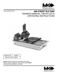
PF10 Power Feed Trim Saw
Owner’s Manual and Operating Instructions
Revision 105
07.2013
Manual Part No. 161090
Caution: Read all safety and operating
instructions before using this equipment.
This manual MUST accompany the
equipment at all times.
Barranca Diamond Products, Inc.
1315 Storm Parkway
Torrance, CA 90501
Toll-Free: (800) 630-7682
Phone: (310) 523-5867
Fax: (310) 257-3063
www.barrancadiamond.com
PF10
Thank you for selecting the Barranca Diamond PF10 Trim Saw. We are certain that you will be pleased with
your purchase. Barranca Diamond takes pride in producing top quality products for hobby and commercial
lapidary users throughout the world.
This owner’s manual contains information necessary to operate and maintain your PF10 Trim Saw safely and
correctly. Operated correctly, your PF10 Trim Saw should provide you with years of service. Please take the
time to familiarize yourself with the PF10 Trim Saw by reading and reviewing this manual.
If you should have questions concerning your PF10 Trim Saw, please call Barranca Diamond at:
(310) 523-5867 or Toll Free: (800) 365-0085.
TABLE OF CONTENTS
SAFETY
Safety Precautions
California Proposition 65 Warning
Electrical Requirements & Grounding Instructions
Product Specifications
3-6
6
7-8
9
OPERATION, ADJUSTMENT & MAINTENANCE
Oil/Coolant
Setup
Inspection
Start Up
Slab Sawing Mode
Trim Sawing Mode
Maintenance
Diamond Blade
Installation & Removal
10
11
12
13-15
16-17
18
19-22
23
24
EXPLODED VIEW AND PART LIST
Exploded View
Part List
Service and Warranty
26-27
28-30
32-34
2
PF10
SAFETY
SAFETY PRECAUTIONS
Read and follow all safety, operating and maintenance instructions. Failure to read and follow these
instructions could result in injury or death to you or others. Failure to read and follow these instructions could
also result in damage and/or reduced equipment life. In order to prevent injury, the following safety precautions
should be followed at all times!
READ OWNERS MANUAL BEFORE USE
Before using this equipment, ensure that the person operating this machine has read and understands all of
the instructions in the manual. Precaution is the best insurance against accidents. Read and understand all
safety precautions, messages, warnings and hazard symbols. You are responsible for your own safety.
ALWAYS USE SAFETY GLASSES
Safety glasses should always be worn when working around power tools. In addition, a face, dust mask or
respirator should be worn if a cutting operation is dusty. Everyday eyeglasses only have impact resistant
lenses and may not prevent eye injury-they are NOT safety glasses.
USE PROPER APPAREL
Do not wear loose clothing, gloves, neckties, rings, bracelets, or other jewelry that may be caught in moving
parts. Non-slip footwear is recommended. Wear protective hair covering to contain long hair. Hand protection
(plastic gloves) and a shop bib are recommended during sawing to prevent stains to clothing. Avoid prolonged
exposure of skin to the sawing lubricant and wash skin immediately after contact. Do not touch the work
material until the motor is off and the machine has come to a complete stop.
ALWAYS USE HEARING PROTECTION
To reduce the possibility of hearing loss, always use hearing protection when operating power equipment.
KEEP GUARDS IN PLACE
In order to prevent injury, never operate the saw with out the guards in place!
REMOVE ADJUSTING KEYS AND WRENCHES
Form a habit of checking to see that keys and adjusting wrenches are removed from the power tool before it is
turned on.
DO NOT USE IN DANGEROUS PLACE
Do not use power tools in damp or wet locations nor expose them to rain. Always keep the work area well
lighted.
ELECTRICAL SHOCK
Never touch electrical wires or motor components while the motor is running. Exposed, frayed or worn
electrical wiring and plugs can be sources of electrical shock that could cause severe injury or burns.
DISCONNECT TOOLS
Power tools should always be disconnected before servicing or when changing accessories, such as blades,
bits, cutters, and the like.
REDUCE THE RISK OF UNINTENTIONAL STARTS
Make sure the ON/OFF switch is in the OFF position before plugging in a power tool.
3
PF10
SAFETY
ROTATING OR MOVING PARTS
Keep hands, feet, hair, and clothing away from all moving parts to prevent injury. Never operate the engine with
covers, shrouds, or guards removed.
MAINTAIN TOOLS WITH CARE
Keep tools clean for the best and safest performance. Always follow maintenance instructions for lubricating,
and when changing accessories.
KEEP WORK AREA CLEAN
Cluttered work areas and benches invite accidents.
DO NOT USE IN DANGEROUS OR HAZARDOUS ENVIRONMENTS
Do not operate equipment in dangerous or hazardous environments. Do not use power tools in damp or wet
locations nor expose them to rain. Always keep the work area well lighted. Always work in a well ventilated
area.
KEEP CHILDREN AWAY
All visitors and children should be kept a safe distance from the work area. Keep power cords disconnected
when tool is not in use.
MAKE THE WORKSHOP KID PROOF
Make the workshops kid proof by using padlocks, master switches and by disconnecting all power cords.
USE THE RIGHT TOOL
Do not force a tool or an attachment, to do a job that it was not designed to do.
SECURE WORK
Clamps or a vise should be used to hold work whenever practical. Keeping your hands free to operate a
power tool is safer.
DO NOT FORCE THE TOOL
A power tool will do a job better and safer operating at the rate for which it was designed.
USE THE RIGHT TOOL TO SERVICE THE SAW
Do not force a tool or an attachment when servicing or operating this power tool. Use the correct tools for
service or adjustments.
DO NOT OVERREACH
Keep proper footing and balance at all times by not overreaching.
DO NOT OPERATE A TOOL WHEN TIRED
When tired, take a break and relax.
4
PF10
SAFETY
DIRECTION OF FEED
Always feed work into a blade or cutter in the direction shown in this manual. Al blades, grinding wheels or
polishing belts should always be installed such that rotation is in the direction of the arrow imprinted on the
blade, wheel or belt.
ONLY OPERATE AT THE PROPER SPEED
Severe personal injury and damage to the motor or equipment can result if operated at speeds above
maximum.
NEVER LEAVE A TOOL RUNNING UNATTENDED – TURN POWER OFF
Do not leave a tool until it comes to a complete stop. Always turn the tool off and disconnect the power cord to
its source when leaving the work area or when work is finished. Do not leave extension cords attached to the
power cord or power receptacle (wall outlet) when leaving the work area.
CHECK FOR DAMAGED OR WORN PARTS
Before using a power tool, check for damaged parts. A guard or any other part that is damaged should be
carefully checked to determine if it would operate properly and perform its intended function. Always check
moving parts for proper alignment or binding. Check for broken parts and mountings and all other conditions
that may affect the operation of the power tool. A guard, or any damaged part, should be properly repaired or
replaced.
USE RECOMMENDED ACCESSORIES AND PARTS
Consult the owner’s manual for recommended accessories and parts. Using improper parts and accessories
may increase the risk of personal and/or bystander injury.
USE THE PROPER EXTENSION CORD
If using an extension cord make sure it is in good condition first. When using an extension cord, be sure to
use one heavy enough to carry the current your product will draw. An undersized cord will cause a drop in
line voltage that will result in a loss of power and overheating. TABLE 1, shows the correct AWG size to use
depending on cord length and nameplate ampere rating. If in doubt, use the next heavier gage. The smaller
the gage number, the heavier the cord.
USE THE PROPER POWER SOURCE
This tool is only to be used with a 120 volt 60 HZ power source. Insure power source is at least 15 amps and
110 to 120 volts. Low voltage current can adversely effect electric motor performance and overall life.
USE THE RECOMMENDED COOLING AND LUBRICATING FLUIDS
Never operate a tool that requires coolant or lubricate dry. This can lead to shortened tool life, tool damage and
personal injury.
MAINTAIN TOOLS WITH CARE
Keep the diamond blade sharp, the sawing lubricant clean and reservoir filled to the correct level for the best
and safest performance. Always follow the maintenance instructions for sharpening the blade, lubricating and
servicing the PF10.
5
PF10
SAFETY
WARNING
Sawing, grinding and drilling generates dust. Excessive airborne particles may cause irritation to eyes, skin
and respiratory tract. To avoid breathing impairment, always employ dust controls and protection suitable to the
material being sawed, ground or drilled; (See OSHA 29 CFR Part 1910.1200). Diamond Blades improperly used
are dangerous. Comply with American National Standards Institute Safety Code, B7.1 and Occupational Safety
and Health Act covering Speed, Safety Guards, Flanges, Mounting Procedures, General Operating Rules,
Handling, Storage and General Machine Conditions.
CALIFORNIA PROPOSITION 65 WARNING
Some dust created by power sanding, sawing, grinding, drilling, and other construction activities contain
chemicals known (to the State of California) to cause cancer, birth defects or other reproductive harm. Some
examples of these chemicals are:
• Lead, from lead-based paints
• Crystalline silica from bricks, cement and other masonry products
• Arsenic and chromium, from chemically treated lumber
For further information, consult the following sources:
http://www.osha.gov/dsg/topics/silicacrystalline/index.html
http://www.cdc.gov/niosh/docs/96-112/
http://oehha.ca.gov/prop65/law/P65law72003.html
http://www.dir.ca.gov/Title8/sub4.html
Your risk from these exposures varies depending on how often you do this type of work. To reduce your
exposure to these chemicals, work in a well-ventilated area, and work with approved safety equipment, such as
dust masks that are specially designed to filter out microscopic particles. Where use of a dust extraction device
is possible, it should be used. To achieve a high level of dust collection, use an industrial vacuum cleaner.
6
PF10
SAFETY
ELECTRICAL REQUIREMENTS AND GROUNDING INSTRUCTIONS
In order to prevent potential electrical shock and injury, the following electrical safety precautions and symbols
should be followed at all times!
In case of a malfunction or breakdown, grounding provides a path of least resistance for electric current to
reduce the risk of electric shock. This tool is equipped with an electric cord having an equipment-grounding
conductor and a grounding plug. The plug must be plugged into a matching outlet that is properly installed and
grounded in accordance with all local codes and ordinances.
• Do not modify the plug provided – if it will not fit the outlet; have the proper outlet installed by a qualified
electrician
• Improper connections of the equipment-grounding conductor can result in a risk of electric shock. The
equipment-grounding conductor is the insulated conductor that has an outer surface that is green, with or
without yellow stripes. If repair or replacement of the electric cord or plug is necessary, do not connect the
equipment-grounding conductor to a live terminal
• Check with a qualified electrician or service personnel if the grounding instructions are not completely
understood, or if in doubt as to whether the tool is properly grounded
• Use only 3-wire extension cords that have 3-prong grounding plugs and 3-pole receptacles that accept the
tool’s plug
• Repair or replace a damaged or worn cord immediately
This tool is intended for use on a circuit that has an outlet that looks like the one shown in Sketch A of Figure
1. The tool has a grounding plug that looks like the plug illustrated in Figure 1. A temporary adapter, which
looks like the adapter illustrated in sketches B and C, may be used to connect this plug to a 2-pole receptacle
as shown in Sketch B, if a properly grounded outlet is not available. The temporary adapter should be used
only until a properly grounded outlet can be installed
by a qualified electrician. The green-colored rigid ear,
lug, and the like, extending from the adapter, must be
connected to a permanent ground such as a properly
Metal Screw
grounded outlet box.
Cover of Grounded
Outlet Box
Note: Use of a temporary adapter is not permitted in
Canada
Grounding Pin
To reduce the risk of electrocution, keep all
connections dry and off the ground.
(A)
(B)
ADAPTER
A Ground Fault Circuit Interrupter (GFCI) should be
provided on the circuit(s) or outlet(s) to be used for this
power tool. Receptacles are available having built-in
GFCI protections and may be used for this measure of
safety.
(C)
Grounding
Means
Figure 1
Grounding Pin
Figure 1
7
(D)
PF10
SAFETY
To avoid the possibility of the appliance plug or receptacle getting wet, position the saw to one side of a wall
mounted receptacle. This will prevent water from dripping onto the receptacle or plug. A “drip loop,” shown in
FIGURE 2, should be arranged by the user to properly position the power cord relative to the power source.
The “drip loop” is that part of the cord below the level of the receptacle, or the connector, if an extension cord
is used. This method of positioning the cord prevents the travel of water along the power cord and coming in
contact with the receptacle.
If the plug or receptacle gets wet, DO NOT unplug the cord. Disconnect
the fuse or circuit breaker that supplies power to the tool. Then unplug and
examine for presence of water in the receptacle.
Use only extensions cords that are intended for outdoor use. These extension
cords are identified by a marking “Acceptable for use with outdoor appliances;
store indoors while not in use.” Use only extension cords having an electrical
rating not less than the rating of the product. Do not use damaged extension
cords. Examine extension cords before using and replace if damaged. Do not
abuse extension cords and do not yank on any cord to disconnect. Keep cords
away from heat and sharp edges. Always disconnect the extension cord from
the receptacle before disconnection the product form the extension cord.
Figure 2
To reduce the risk of electrocution, keep all connections dry and off the ground. Do not touch the plug with wet
hands.
Use of under size extension cords result in low voltage to the motor that can result in motor burnout and
premature failure. Barranca Diamond warns that equipment returned to us showing signs of being run in a
low voltage condition, through the use of undersized extension cords will be repaired or replaced totally at the
customers expense. There will be no warranty claim.
To choose the proper extension cord,
• Locate the length of extension cord needed in TABLE 1 below.
• Once the proper length is found, move down the column to obtain the correct AWG size required for that
length of extension cord.
EXTENSION CORD LENGTH
115V
25'
50'
75'
100'
150'
200'
250V
50'
100'
150'
200'
300'
400'
0-5
16
16
16
14
12
12
5.1 - 8
16
16
14
12
10
•
8.1 - 12
14
14
12
10
•
•
12.1 - 15
12
12
10
10
•
•
15.1 - 20
10
10
10
•
•
•
Nameplate
Amperes
Table 1
8
PF10
Shipping Weight
Main Motor
Horsepower
Motor Voltage
Amperage
Motor RPM
Motor Arbor Diameter
Duty
Motor Arbor Bearings
Blade Capacity
95 lbs. (115 lbs. crated)
Baldor Model 17K017W470
1/3 HP
110 volt/60Hz
5.8 Amps
1725 RPM Fixed
1/2"
Continuous
Ball Bearings, permanently sealed
8", 9" or 10" diameter
Power Feed Motor
Horsepower
Motor Voltage
Motor RPM
Torque
Rotation
Motor Arbor Diameter
Motor Arbor Bearings
Dayton Shaded Pole AC Gear motor (Model 3M098)
1/250 HP
110 volt/60Hz
4 RPM (full load) Fixed
18 inch-lbs.
Clockwise facing the shaft
5/16"
Sleeve-bushing type, permanently sealed
SPECIFICATIONS
Power Feed Toggle Switch Control Positions:
1. BACK/POWER FEED Position (toward operator)– Provides power from the main motor to the blade arbor
and power feed motor.
2. MIDDLE/OFF Position – Both power feed and main motors off.
3. FORWARD/MANUAL FEED Position (away from operator) Provides power from the main motor to the blade
arbor only.
Blade Arbor Bearings: Permanently sealed 5/8" OD shaft ball bearings press fit into aluminum housing (must
be ordered with aluminum housing as an arbor assembly when bearings are worn out.)
Blade Arbor Flanges: Aluminum, 2" OD x 5/8" bore.
Power Feed Threaded Rod: 1-1/2" long x 3/8"-24 fine thread stainless steel rod.
Power Feed Clutch Block: Two piece: lower silicon bronze half-threaded 3/8"-24 fine thread and upper brass
friction block (unthreaded).
Rock Vise Capacity: 4" .
Cross Feed Index Movement per Revolution of Handle: 1/16".
Power Feed In-Feed Vice Advancement Rate: approximately 3/16 of an inch per minute.
Blade Lubricant Requirements: 1/2 gallon of oil to adequately cover the bottom of a 10” blade and 3/4 gallon for
an 8” blade.
9
PF10
OIL/COOLANT
RECOMMENDED CUTTING OILS
Never run a diamond blade dry as this can immediately damage your blade. Use one of the oils/coolants recommended
below. Coolant should be kept clean and below 100° F. Sludge should be removed periodically and replaced with fresh
coolant so that your cuts will be clean and your blades will not be damaged.
Shell Diala Ax and Amber Neutral 100
Non-hazmat replacement oil for electrical transformer cooling. Excellent lubricating properties for blades and saw parts.
Flushes sludge from rock easily, degreases easily, and sludge settles in saw tank well. In Southern California, Shell Diala
Ax can be purchased from Dion and Sons, Inc (www.dionandsons.com).
Chevron Texaco Bright-Cut
A chlorine-free cutting oil with reduced sulfur and fat content. Light in color and low in odor.
Hyvolt II
Electrical transformer cooling oil. A highly refined petroleum product, available from some non-Shell oil distributors, typically only in 55 gallon drums. Same properties and performance as Shell Amber Neutral 100.
Chevron Superla #5
Food grade mineral oil. Non-hazardous lubricating oil for bakeries, breweries and food processing machinery. Good lubricating properties, degreases and settles sludge well. Can go rancid over time (1 year or less).
AVATEC 80
Food grade mineral oil, excellent for slab sawing in all our slab saws.
Texaco ALMAG
Pure petroleum based machining cutting oil. Good for slab sawing but very strong odor. Often the cheapest priced oil
available but odor is tough to eliminate.
Roc Cut
Roc Cut from Diamond Pacific is a new synthetic water soluble cutting additive with rust inhibitors. Mix 30 to 1 (water to
Roc Cut).
Roc-Oil
Roc-Oil from Diamond Pacific is an oil coolant for heavy duty cutting. Provides excellent blade protection and will not
cause rust to your blade or saw.
Under NO circumstances should any of the following fluids be used in any of our lapidary saws:
Automotive Antifreeze Coolant
Ethylene glycol based automotive antifreeze and its vapors are considered hazardous and toxic. Propylene glycol based
antifreeze is nontoxic but has practically no lubricating properties; it functions as a coolant only and its use will lead to
rapid blade wear and dulling.
Automotive Transmission Fluid
Does not have adequate lubricating proprieties for our saws; vapors are considered hazardous and toxic.
Water
A good coolant but has no lubricating properties and causes rust and degradation of exposed iron and steel parts. Causes
rapid blade dulling and premature wear. Use of water voids the warranty on all Barranca Diamond saws.
CNC Machining Fluids
Water soluable synthetic coolants (i.e. Valenite or Cimtool) are often mixed in a 20:1 blend with water. Fluid vapors are
considered hazardous. These fluids do not have adequate lubricating or rust inhibiting properties for the cast iron and
steel parts in our slab and trim saws.
Diesel, Heating Oil and Kerosene
Very flammable with a low flash point. At least 3 of our commercial cutting customers in Arizona and Pacific Northwest
have burned down their shops using these fluids. Can be very tough to degrease the residue and aroma out of the cut
slabs. These fluids are cheap, but very hazardous to use. Diesel is a benzene compound which is carcinogenic. All these
fluids can cause severe skin rashes and other ailments.
10
PF10
SETUP
CONTENTS
In the shipping crate, you will find one Barranca Diamond PF10 Trim Saw assembly (saw, motor, baseboard,
spray hood and 10" x 0.040 x 5/8 303 Pro diamond blade). One package of six rubber feet and mounting
screws, and one 1" x 1" x 6" sharpening stick.
Saw Assembly
Rubber Feet and
Mounting Screws
Sharpening Stick
UNPACKING AND ASSEMBLY
Your PF10 Trim Saw has been shipped from the factory thoroughly inspected and tested. Remove the crating
material (wood and plastic) from the baseboard and around the saw with a Phillips and standard screwdriver
and box cutter knife. Remove the spray hood from the saw and remove the protective covering from either side
of the acrylic window.
Once removed from the crate, locate the six rubber feet and screws in a zip-lock plastic bag. Each rubber foot
mounts to the underside of the baseboard in predrilled mounting holes. This step should be performed before
sawing lubricant is added to the oil reservoir. To mount the feet, first remove the two Phillips-head machine
screws that secure the belt guard to the saw table. Then, while supporting the left (vise) side of the saw table,
remove the four flat-head machine screws (fig 1) that secure the saw table to the reservoir tank and remove the
saw table. Please note: the saw table will fall off the reservoir if not supported once the final mounting screw is
removed! . At this point you can reattach the saw table and belt guard, or continue to the start up section of this
manual (page 9).
Fig 1. Removing the saw table from the reservoir tank
Fig 2. Installing the rubber feet
TRANSPORT
For ease of transport, place the hood window over the saw table and tape the hood to the table to prevent
vibration from scraping the paint off both the table and hood during travel. All sawing lubricant should be
removed from the reservoir during transport of the saw.
11
PF10
INSPECTION
PRESTART INSPECTION
Place the PF10 Trim Saw on a flat surface such as a bench top or table.
Set the toggle power switch to the MIDDLE/OFF position (fig 3).
FORWARD/MANUAL FEED
Saw Motor On
Power Feed Off
BACK/POWER FEED
Saw Motor On
Power Feed On
MIDDLE/OFF
Saw Motor Off
Power Feed Off
Fig 3. Toggle power switch positions and functions
Prior to operating the PF10 Trim Saw, you must fill the oil reservoir so that the lubricant fluid covers the bottom
1/4" of the blade (fig 4). 1/2 gallon of oil will adequately cover the bottom of a 10” blade and 3/4 gallon will be
sufficient for an 8” blade. Do not overfill the oil reservoir as excess fluid will result in unnecessary spraying of
fluid while sawing and possibly cause damage to the arbor and motor.
To add lubricant, first remove the two Phillips-head machine screws that secure the belt guard to the saw table.
Then, while supporting the left (vise) side of the saw table, remove the four flat-head machine screws (fig 5)
that secure the saw table to the reservoir tank and remove the saw table. Please note: the saw table will fall off
the reservoir if not supported once the final mounting screw is removed!
The 303 Pro blade is manufactured to cut in either a petroleum, mineral or synthetic water soluble oil saw
lubricant. Although water can be used with the PF10 Trim Saw, it is not recommended as the steel arbor shaft
can rust. In addition, poor sawing performance and short blade life can result. If water must be used, it is
recommended that a rust inhibitor such as Tool Cool (8 oz. Tool Cool to 1 gallon water) be added.
Fig 4. Coolant level should cover the bottom 1/4"
of the blade
Fig 5. Removing saw table from reservoir tank
12
PF10
START UP
START UP
With the table removed from the reservoir, inspect the motor mounts and belt tension. Check the four motor
mounting nuts (fig 6) to insure they are tight and the motor is secure. The V-belt is adjusted and tensioned at
the factory. However, if the motor mounts should become loose during shipping or usage readjust the motor
mounting nuts so that no more than 1/2" of belt deflection occurs when the belt is depressed by fingertip
pressure (fig 7).
Fig 6. Motor mount adjustment points
Fig 7. V-belt correctly tensioned
When you have confirmed that the belt is properly tensioned and the motor mounting nuts are secured,
reattach the saw table with the four mounting screws. Be sure the cork tank gasket is correctly positioned
between the saw table and coolant reservoir (fig 8) and the proper amount of lubricant is in the reservoir before
reattaching the saw table.
Fig 8. Cork gasket in place
13
PF10
START UP
START UP (continued)
Check to ensure that the toggle power switch is in the MIDDLE/OFF position. Plug the power cord from the
motor into the power feed receptacle (fig 9) on the power feed box (located on the front of the saw). The power
cord from the power feed box should be attached to GFCI receptacle.
Fig 9. Motor cord attached to the power feed box receptacle
If an extension cord is used to attach to the PF10 Trim Saw, use an extension cord that is at least 14 gauge
wire and no longer than 25 feet.
To perform a power up test on the PF10, first disengage the vise clutch by turning the clutch handle to the 12
o’clock position (fig 10) and then move the rock vise to the front (operator’s) end of the saw table (fig 12).
Fig 10. Clutch handle in disengaged (12 o’clock) position
Fig 11. Clutch handle in engaged (9 o’clock) position
14
PF10
START UP
START UP (continued)
Once the rock vise is placed in the far back position, lock the clutch handle in the 9 or 3 o’clock position (fig 11).
Now engage the power feed and main motor to begin advancing the vise and rotating the blade by pushing
the toggle to the rear or to the BACK/POWER FEED position (fig 3). The 4 RPM power feed motor (fig 13) will
slowly move the vise toward the blade (approximately 3/16 of an inch per minute). The saw hood does not need
to be placed over the saw table during this power test. Once you have confirmed the vise is moving toward
the blade and the blade is turning, this indicates the saw is functioning properly. The saw can be turned off by
flipping the toggle switch to the MIDDLE/OFF position.
Fig 12. Rock vise positioned at front of saw
Fig 13. Power feed motor and screw feed rod
15
PF10
SLAB SAWING MODE
SLAB SAWING MODE
To begin slabbing of rock material, turn the toggle switch to the MIDDLE/OFF position (fig 3) and secure the
material in the rock vise by opening the vise jaws wide enough to fit the material to be cut. Retighten the jaws
with the wing nut screws on the rock vise (fig 14). The vise should be positioned close to (but not touching) the
diamond blade by placing the clutch lever in the disengaged 12 o’clock position (fig 10) and moving the vise
forward toward the blade (fig 15).
Fig 14. Rock vise wing nut screws
Fig 15. Material positioned in vise near blade prior to cutting
Once the vise is positioned close to the blade, loosen the wing nut on the front of the vise (fig 16) and laterally
move the vise to the desired slab thickness to be cut by turning the cross-feed handle (fig 17) clockwise or
counterclockwise. Retighten the wing nut on the vise.
Fig 16. Vise cross-feed locking wing nut
Fig 17. Cross-feed handle
16
PF10
SLAB SAWING MODE
SLAB SAWING MODE (continued)
At this point, the clutch handle should be engaged by turning it to the 3 or 9 o’clock position (fig 11). Slabbing of material can now be initiated by engaging the power feed and blade by moving the toggle switch to the
BACK/POWER FEED position (fig 3). The rock vise and material will move forward into the blade and the slab
will be cut from the vised material. The vise will proceed to move along the power feed rail until the automatic
feed shut-off collar is engaged by the rock vise and the shut off collar on the 1/4" rod located under the rail (fig
18). Once the shut-off-collar is encountered, the saw will shut off by moving the toggle to the MIDDLE/OFF
position.
Fig 18. Automatic feed shut-off collar
Fig 19. Metal splash hood in place on cutting table
The shut-off collar can be adjusted to any position along the length of the 1/4" rod by loosening the thumb
screw attached to the collar and sliding the collar to the desired position and retightening. After the slab has
been cut and the power feed is shut down automatically, the user can reposition the rock vise to the next position in front of the blade. Adjust the vise to begin the next slab cut by disengaging the clutch and sliding the
rock vise to a position in front of the blade again. Once the clutch is reengaged by turning the handle to the 3
or 9 o’clock position, the next slab can be cut.
Place the metal splash hood on the table (fig 19), so that spray from the cutting fluid (oil or water) during sawing
will be contained and drain back into the reservoir. Excess cutting fluid that builds up on the table during slab
or trim sawing will drain back into the reservoir through the blade slot and eight drain holes adjacent to the slot.
Rock chips and debris from sawing should be removed from the table area periodically to prevent interfering
with free movement of the vise over the table during automatic or manual feeding.
17
PF10
TRIM SAWING MODE
TRIM SAWING MODE
Slabbing of rock material to uniform thicknesses using the PF10 Trim Saw is best performed using the automatic power feed mode. However, manual trimming of slabs to desired shapes (preforming) can be achieved
using the saw in the FORWARD/MANUAL FEED position (fig 3).
Fig 20. Rock vise on table for power feed operation
Fig 21. Rock vise in raised position for manual slabbing
To use this mode, first place the toggle in the MIDDLE/OFF position (fig 3) and flip the vise assembly over the
power feed rail by loosening the thumb screw on hinged portion of the vise (fig 22) and rotating the vise so that
it pivots off the saw table (fig 21). At this point the saw is ready to be used in the manual mode (with only the
blade motor activated) for manual trimming of slabs by placing the toggle in the FORWARD/MANUAL FEED
position (fig 3).
Fig 22. Vise lock thumb screw
Fig 23. Blade guard thumb screw
The rock slab to be trimmed should rest flat and firmly on the saw table in front of the blade prior to moving the
toggle switch to the FORWARD/MANUAL FEED position. The user should use light but firm pressure to cut the
slab in the manual mode letting the blade do the work and not force the slab into the blade.
The blade guard height can be adjusted by turning the thumb screw at the rear mounting position of the guard
(fig 23). Under no circumstances should the blade guard be removed. While the blade guard will reduce
excessive splash and spray of cutting fluid during rock trimming, it is advised to wear personal protective gear
(safety glasses, gloves and a shop bib) during manual mode trimming.
18
PF10
MAINTENANCE
CUTTING LUBRICANT REPLACEMENT
The PF10 Trim Saw requires periodic routine maintenance to remove the build up of rock mud (sludge) and
dirty lubricating fluid from the reservoir. It will be apparent to the user that the lubricating fluid is dirty and
needs to be changed if the oil residue on the saw table after cutting is thick and dark with rock sludge build up.
The oil liquid can be removed rapidly using the drain pipe attached to the bottom drain hole at the base of the
oil reservoir (fig 24).
Fig 24. Drain pipe
A five gallon bucket or collection container can be placed under the outlet cap of the pipe and the cap removed
with an adjustable wrench to let the free oil flow into the bucket for proper disposal. It may be necessary to
hold the pipe with gripping pliers to prevent it from unthreading from the reservoir when removing the cap. The
sludge residue will likely not flow through the drain pipe and will remain inside the oil reservoir. Therefore, the
sludge should be removed when the slab saw oil lubricant is drained by removing the belt guard, saw table and
blade, and extracting the sludge with a spatula or spoon. Once the sludge is removed, wipe clean the inside
of the tank with a disposable towel and refill the cutting lubricant to cover the bottom 1/4" of the blade (fig 4).
Dispose of the used oil and sludge properly. Be sure to check the fluid level of the cutting lubricant inside of the
oil reservoir after every 3 to 5 hours of use as the fluid will be absorbed onto the rock material, combine with
rock mud (sludge) and be lost due to heat and evaporation.
19
PF10
MAINTENANCE
V-BELT
The PF10 Trim Saw blade arbor is powered by an AX-24 rubber V-belt from the electric motor. The V-belt is
correctly tensioned at the factory. However if it is necessary to service the belt, unplug the PF10 Trim Saw
from its power source and remove the fasteners which secure the belt guard housing to the saw table and
motor. If the belt tension should become too loose, poor sawing performance or slipping will result. The belt
tension should be checked periodically by removing the guard and depressing the belt in the middle between
the motor and blade pulleys.
Fig 25. V-belt correctly tensioned
Fig 26. Motor mount adjustment points.
There should be 1/2" of deflection once the belt is pushed down (fig 25). If the belt is too tight (i.e. no deflection)
the electric motor and blade arbor bearings may be overheated and wear out prematurely or the motor may
shut off due to overheating. Belt tension can be adjusted by loosening the four mounting nuts (fig 26) attached
to the four studs welded to the rear of the oil reservoir and sliding the motor cradle base up or down to increase
or decrease belt tension. Be sure to adequately retighten the motor mount nuts and replace and attach the belt
guard to the saw table.
POWER FEED SYSTEM AND VISE
The power feed system utilizes a 4 RPM AC gear motor mounted inside of the rectangular box attached to
the front of the PF10 Trim Saw (fig 27). There is no need to service or lubricate the power feed motor unless
the motor fails and the screw feed rod fails to rotate when the feed is engaged. If the set screw that fastens
the power feed motor to the feed rod (fig 28) loosens during use or shipping, the rod will not rotate and move
the vise toward the blade. This rod set screw can be tightened with a US standard Allen/hex wrench should it
loosen.
20
PF10
MAINTENANCE
POWER FEED SYSTEM AND VISE (continued)
Fig 27. Power feed gear box and screw feed rod
Fig 28. Power feed coupling
Periodically the user should apply a thin coat of lubricating grease (wheel bearing or lithium grease) to the
3/8"-24 screw feed rod under the rails to prevent the screw feed rod threads from becoming prematurely
worn. If the threads on both the stainless steel screw feed rod and bronze clutch block should become worn
or “flattened” the clutch block will not securely engage with the screw rod and it may disengage from the
clutch block and not automatically advance the rock vise. A replacement bronze clutch can be obtained from
Barranca Diamond. The rock vise assembly has cross feed threads attached to an indexing or crank handle
to laterally adjust the vise so that slab thickness is accurately controlled before each slab cut. These threads
should be lubricated periodically with wheel bearing or lithium grease to allow for ease of rotation of the cross
feed crank.
Should the wooden jaws on the vise become worn or start delaminating, replacement jaws can be made from
1/2" plywood.
BLADE ARBOR ASSEMBLY AND PULLEYS
The PF10 Trim Saw is equipped with a 5/8"-18 left-hand fine threaded arbor shaft with sealed ball bearings
mounted in an aluminum bearing arbor housing. A 2" OD x 5/8" bore die cast zinc coated pulley is mounted
on the shaft outside the oil reservoir. Unusual noises emanating from the saw tank or arbor area, slower than
normal cutting speeds and overheating of the shaft or belt are indications of arbor/bearing wear. Using the saw
with a worn arbor/bearing assembly can result in permanent damage to other components of the saw. A new
arbor/bearing assembly can be purchased from Barranca Diamond. It is sold only as a complete unit as the
bearings are installed in the aluminum housing by the factory.
21
PF10
MAINTENANCE
BLADE ARBOR ASSEMBLY AND PULLEYS (continued)
Fig 29. Arbotng bolts
Fig 30. Pulley set screw
Periodically, check the tightness of the four blade arbor housing mounting bolts (fig 29) to make sure they
are securely tightened to the oil reservoir. Should the 2 inch OD die cast pulleys on either the motor or blade
arbor shaft need to be removed or replaced, loosen the set screw on the hub (fig 30) of each pulley with a US
standard Allen/hex wrench to remove the pulley from the shaft.
MAIN MOTOR
The Cab Combo is equipped with a Baldor 1/3 HP 1725 RPM single-phase 120 volt 60 Hz 8 amp motor. The
motor shaft has sealed ball bearings and requires no lubrication. The motor is protected from thermal damage
(overheating) with an automatic shut-off switch. If the motor overheats it will automatically shut off and restart
once its internal components cool down and the motor is restarted manually (red button). Be sure to shut off
the main motor by placing the switch lever to the OFF position and disconnecting the power source. After allowing the motor to cool (2 to 3 hours), push the red reset button on the side of the motor (fig 31) and restart
the unit by turning the switch to ON. If the motor does not restart after a cool down period, remove the motor
and have an authorized repair service center for Baldor inspect the motor. Barranca Diamond can refer you to
an authorized motor repair service center in your area.
Please note: On PF10 trim saws prior to serial number 1260, the motors
do not have reset switch. Therefore it is imperative that if the saw motor
should stop during operation that the power to the main motor be shut off
by placing the toggle switch in the MIDDLE/OFF position as the motor will
restart automatically once cooled down.
22
PF10
DIAMOND BLADE
Fig 31. Motor reset button.
DIAMOND BLADE
Periodically, the diamond blade on the PF10 Trim Saw will need to be resharpened should slow or poor sawing
performance occur. Dull or “glazed over” diamonds will either not cut thus stalling the saw and shutting off
the motor, or the rock vise and rock material will ride up the blade and possibly damage the blade or “dish”
the core. Once the saw begins to labor or struggle to cut gemstones, the user is advised to use the provided
sharpening stick and resharpen the blade. Resharpening can be performed either with the automatic
power feed (stick secured in vise) or manually with the power feed disengaged and a few slabs cut from the
sharpening stick. If no sharpening stick is available, the user could use an abrasive material such as cinder
block or brick to remove the glazing over the diamonds on the rim of the blade.
Eventually all diamond blades wear out and must be replaced with a new blade. New continuous rim diamond
blades (303 Pro for example) should be mounted on the blade arbor so that the arrow marked on the steel
core is pointing in the direction of blade rotation while in use. If the arrow cannot be found, use a hand lens or
magnifying glass to inspect the rim and see the head and tail of any individual diamond. To correctly mount
the blade, the head of the diamond must cut first into the rock with the tail trailing behind. For notched rim
diamond blades (297 or 301 models for example), it does not matter which way the blade is orientated on the
arbor shaft.
DIAMOND BLADE INSTALLATION AND REMOVAL
Fig 32. Blade arbor and inner flange
Fig 33. Blade arbor, blade, outer flange and jam nut
To access the diamond blade for inspection or replacement, loosen the four flat-head screws (fig 1) that secure
the saw table to the reservoir tank and remove the saw table. The blade is mounted on the 5/8“ blade arbor
(fig 32) between two aluminum blade flanges. A 5/8"-18 left-handed jam nut secures the flanges and blade to
the arbor shaft (fig 33). Hold the blade with one hand and use a 15/16" wrench to tighten or loosen the jam nut
(fig 34). The jam nut has left handed threads and is turned counterclockwise to tighten and clockwise to loosen.
DO NOT OVER TIGHTEN THE JAM NUT! Note: blade flanges must always be installed with their concave or
recessed side (fig 35) facing the blade.
23
PF10
INSTALL/REMOVAL
DIAMOND BLADE INSTALLATION AND REMOVAL (continued)
Reattach the saw table with the four mounting screws. Be sure the cork tank gasket is positioned correctly
between the saw table and coolant reservoir and that the proper amount of lubricant is in the reservoir before
attaching the saw table.
Fig 34. Hold the blade with one hand use a 15/16" wrench
to turn the jam nut. Do not over tighten
Fig 35. Convex or recessed side of blade flange
24
NOTES
25
PF10
EXPLODED VIEW
P4
P1
P3
D7
D2
P5
D4
D8
D3
D5
P2
D1
G5
D13
D6
G4
D8
G1
G3
D12
D7
D11
D9
M3
A4
A5
G2
A1
D10
F2
M1
N2
F1
A2
N4
N1
A3
F3
N3
H1
A6
M2
H2
L12
L1
L11
H4
L10
L2
H3
C1
C1A
L6
C2
L9
L8
L7
L4
L5
H5
L3
L13
26
PF10
EXPLODED VIEW
K1
K3
K2
K9
K5
K4
K8
K6
K13
K7
K16
K10
K11
K12
E3
E4
K15
K14
E7
E2
E1
J8
E6
E5
J2
J4A
J1
J6
J3
J4
J5
J7
J9
27
PF10
Item
A
A1
A2
A3
A4
A5
A6
Description
Assembly, Accessories
Guard, Splash
Screw, Round Head Machine 10-32 x 1"
Spacers, Splash Guard
Washer, Flat SAE # 10
Nut, Hex 10-32
Blade, MK-303 10 x 040 x 5/8"
C
C1
C1A
C2
PARTS LIST
Qty
Part #
1
2
2
2
2
1
161023
161042
161076
154369
156269
153696
Assembly, Tank
Tank, Oil or Water
Screw, Hex HD 5/16"-18 x 1-1/4"
Plug, Drain 1/2"
1
4
1
161016
153950
161021
D
D1
D2
D3
D4
D5
D6
D7
D8
D9
D10
D11
D12
D13
Assembly, Holding Vise
Vise, Front Jaw
Vise, Rear Jaw
Wood Liner, Front Jaw
Wood Liner, Rear Jaw
Screw, Flat HD 10-32 x 1/2"
Nut, Hex 3/8"-16
Nut, Wing 3/8"-16
Washer, Flat SAE 3/8"
Handle, Cross Feed
Collar, Side Feed
Screw, Set 10-32 x 3/16"
Rod, Threaded 3/8"-16 x 6"
Rod, Threaded 3/8"-16 x 7"
1
1
1
1
4
1
3
2
1
1
2
2
1
161027
161028
161031
161032
154541
101188
161037
150923
161044
161077
161038
161034
161081
E
E1
E2
E3
E4
E4A
E5
E6
E7
Assembly, Engage
Bracket, Clutch
Handle, Clutch Engage
Clutch
Collar, Clutch Engage
Screw, Set 8-32 x 1/4"
Screw, Rnd Head Machine 10-32 x 1-1/2"
Washer, Flat SAE # 10
Nut, Hex 10-32
1
1
1
1
1
3
5
4
161060
161061
161062
161063
161086
161064
154369
156269
F
F1
Assembly, Belt Guard
Guard, Belt 16 GA. (steel)
1
161072
28
PF10
F2
F3
G
G1
G2
G3
G4
G5
Screw, Round Head Machine 10-32 x 1/4"
Belt, Micro-V
Assembly, Blade Guard
Guard, Blade
Screw, Pan Head Machine 10-32 x 1-3/4"
Washer, Flat SAE # 10
Nut, Acorn 10-32
Thumbscrew, Blade Guard Adj. 1/4-20 x 1/2"
H
H1
H2
H2A
H3
H4
H5
PARTS LIST
2
1
161041
161085
1
1
2
1
1
161068
161039
154369
161040
161025
Assembly, Motor
Motor, 3/4 hp, 120V, 60Hz
Pulley, Motor
Screw, Set 10-32 x 1/2"
Washer, Flat SAE 5/16"
Nut, Hex 5/16"-18
Cord, Power 14/3 SJTWX5-15PX10
1
1
1
8
8
1
161069
161070
161087
151754
101196
158205
J
J1
J2
J2A
J3
J4
J4A
J5
J6
J7
J8
J9
Assembly, Shaft
Shaft, Casting
Pulley, Shaft
Screw, Set 10-32 x 5/16"
Shaft, Blade PF10 Bearing, Shaft PF10
Collar, Shaft Pin
Collar Shaft
Gasket, Shaft
Flange, Blade 2-1/4" OD X 5/8" Arbor
Nut, 5/8"-18 UNF
Screw, Hex HD 5/16"-18 x 1-1/4"
Nut, Hex 5/16"-18
1
1
1
1
1
1
1
2
1
4
4
161075
161020
161088
162562
161017
161089
161043
135830
135848
153950
101196
K
K1
K2
K3
K4
K5
K6
K7
K8
K9
K10
Assembly, Sliding System
Vise, Platform
Screw, Shoulder Thumb 1/4"-20 x 1
Nut, Pem 1/4"-20
Guides, Nylon
Bracket, Drive Screw
Bushing, Shoulder Bronze 5/16"ID, 18/32"OD
Screw, Hex HD 1/4"-20 x 3/4"
Washer, Flat SAE 1/4"
Nut, Hex 1/4"-20
Screw, Round Head Machine 10-32 x 1/4"
29
1
1
1
2
1
1
1
1
1
4
161026
160461
161078
161033
161057
161058
161036
151915
151893
161041
PF10
PARTS LIST
K11
K12
K13
K14
K15
K16
Washer, Flat SAE # 10
Slide Plate, Vise
Slider, Upper Brass
Slider, Lower Brass
Screw, Round Head Machine 10-32 x 1"
Nut, Hex 10-32
1
1
1
1
4
4
154369
161035
161029
161030
161042
156269
L
L1
L2
L3
L4
L5
L6
L7
L8
L9
L10
L11
L12
L13
Assembly, Linear Feed
Housing, Gear Motor
Cover, Gear Motor Housing
Motor, Gear
Receptacle, Electric
Coupling, Drive Screw
Screw, Set 10-32 x 3/16"
Screw, Truss Hd. 8-32 x 1/2"
Bracket, Switch
Cover, Switch Bracket
Switch, Feed
Screw, Round Head Machine 10-32 x 1/4"
Screw, Drive 3/8"-24
Cord, Power 14/3 SJTWX5-15PX10
1
1
1
1
1
2
4
1
1
1
6
1
1
161046
161047
161050
161051
161059
161038
161055
161048
161049
161052
161041
161056
158205
M
M1
M2
M3
Assembly, Table
Table, Saw
Gasket, Table
Screw, Flat HD 1/4"-20 x 1/2"
1
1
4
161022
161019
155812
N
N1
N2
N3
N4
Assembly, On-Off System
Rod, On/Off Switch
Collar, Rod
Screw, Thumb 10-32 x 1/2"
Spring, Rod
1
1
1
1
161065
161066
161067
161082
P
P1
P2
P3
P4
P5
Assembly, Hood
Hood, Steel 16 GA.
Window, Hood 1/8 x 9.2 x 16.6
Clip, Hood Steel 16 GA.
Screw, Round Head Machine 10-32 x 1/4"
Nut, Hex 10-32
1
1
6
6
6
161071
161073
161080
161041
156269
30
NOTES
31
PF10
WARRANTY
Barranca Diamond Limited Warranty
Please complete the warranty registration card and return. Any problems encountered should be directed to
Barranca Diamond Customer Service department at (800) 630-7682 M-F 8am - 5pm PST.
NOTE THIS INFORMATION FOR FUTURE USE:
MODEL NUMBER:
SERIAL NUMBER:
PURCHASE PLACE:
PURCHASE DATE:
Barranca Diamond warrants to the original retail purchaser for a period of 1 year except as noted, from the
date of purchase all products covered by this Warranty to be free of defects in materials and workmanship.
This Warranty shall not apply to any parts that have been subjected to misuse or improper service, that had
been damaged in transit or handling, or that have been altered or repaired by unauthorized representatives.
This Warranty does not cover defects caused by or resulting from misuse, abuse, neglect or damage caused
by accident or the failure to provide reasonable maintenance. This Warranty is void if the product or any of its
individual components is altered or modified by the purchaser or if the product is used in a manner or with a
blade not recommended by the manufacturer.
Any claim arising under this Warranty must be submitted by the original purchaser within the warranty period
specified above, and shall include proof of purchase. During said warranty period Barranca Diamond shall,
at its option, either replace or repair, at no charge to the original purchaser, any parts or components that are
found to be defective by Barranca Diamond. Barranca Diamond shall not be responsible for or obligated to
pay for freight or other transportation related costs or expenses in connection with any defective products or
components that are either returned to Barranca Diamond’s facility or any authorized repair station and/or any
replacement products or components that are shipped from Barranca Diamond pursuant to this Warranty.
Parts and labor needed to maintain products and the replacement of components due to normal wear and tear
are the purchaser’s responsibility and are not covered by this Warranty. All products or components replaced
under warranty become the property of the manufacturer. All replacement parts will be considered to be part
of the original product and any warranty on such parts will expire coincidentally with the original Warranty.
Barranca Diamond will pay for parts and labor in connection with warranty repairs conducted by Barranca Diamond or its authorized repair centers. Replacement part(s) installed by anyone else will be provided without a
charge for such replacement part(s), but this Warranty will not apply to labor charges in connection therewith.
IN NO EVENT SHALL ANY LIABILITY UNDER THIS WARRANTY EXCEED THE REPLACEMENT COST OF
ANY DEFECTIVE PRODUCT OR COMPONENT THEREOF, AND BARRANCA DIAMOND SHALL NOT BE LIABLE FOR ANY INCIDENTAL OR CONSEQUENTIAL DAMAGES OR FOR ANY OTHER DAMAGE OR LOSS
NOT EXPRESSLY ASSUMED AS SET FORTH HEREIN.
The foregoing constitutes an expressed warranty on the terms set forth above and is the only warranty or
warranties applicable to the products it covers. All other warranties, including, without limitation, the implied
warranty of merchantability and/or fitness for a particular purpose or use being denied. This limited warranty is
expressly in lieu of all other warranties, whether expressed or implied.
32
PF10
WARRANTY
Specifics Applicable to Limited Warranty of Diamond Blades and Core Bits:
Laser Welded Blade and Bit Warranty:
If the laser weld between the segment and the steel core or barrel fails during normal use, the blade
or bit will be replaced free of charge. Blades and bits damaged due to careless or improper use are
not covered under this warranty.
Brazed Blade, Bit, and Cup Wheel Warranty:
If the brazed bond between the segment and the core, barrel, or cup fails within the first .050 of segment wear, the blade, bit, or cup will be replaced free of charge. Blades, bits, and cup wheels damaged due to careless or improper use are not covered under this warranty.
Continuous Rim Blade Warranty:
If the bond between the rim and the core fails during normal use, the blade will be replaced free of
charge. Blades and bits damaged due to careless or improper use are not covered under this warranty.
Exclusions:
Barranca Diamond does not warrant the following components, which carry their own manufacturer’s
warranty for the indicated periods:
Electric Motors Manufacturer’s Warranty
Baldor: 1 year
Ryobi: 1 Year
Soga: 1 Year
Gas Engines Manufacturer’s Warranty
Honda: 2 years
Engine Power Information
Engine power ratings are calculated by the individual engine manufacturer and the rating method
may vary among engine manufacturers. Barranca Diamond Products makes no claim, representation
or Warranty as to the power rating of the engine on this equipment and disclaims any responsibility
or liability of any kind whatsoever with respect to the accuracy or the engine power rating. Users are
advised to consult the engine manufacturer’s owners manual and website for specific information
regarding the engine power rating.
33
PF10
REPLACEMENT PARTS
REPLACEMENT PARTS
Replacement parts for this tool may be ordered from your Barranca Diamond distributor or directly from
Barranca Diamond. Please have the following information ready before calling:
•
Model and serial number of the machine
•
Date of purchase
•
Description of parts being ordered (see parts list)
RETURN MATERIALS PROCEDURE
To expedite the service relative to the return of a product purchased through Barranca Diamond, please have
the following information available:
•
Model and serial number of the machine
•
Date of purchase
•
Distributor’s name
Then please call Barranca Diamond at (310) 523-5867 or toll free at 800-630-7682 to obtain a Return Goods
Authorization number (RGA) authorizing the return.
Please Note:
•
Ensure your item(s) are prepaid to the destination
•
Return items must have been purchased within the previous twelve (12) months
•
Follow the packaging instructions in the following section
•
Be sure to include the RGA number, return address and your phone number on or within the
return shipping box.
PACKAGING INSTRUCTIONS
Ship the equipment using its original shipping crate if possible. Secure inside the shipping crate. Ensure all
parts are secured in the packaging to prevent movement. Do not ship the equipment partially exposed.
34
NOTES
35
Barranca Diamond Products, Inc.
1315 Storm Parkway
Torrance, CA 90501
Toll-Free: (800) 421-5830
Phone: (310) 539-5221
Fax: (310) 539-5158
www.barrancadiamond.com