1
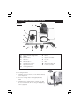
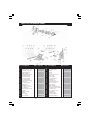
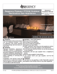
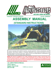
POWERWASHER
Model: PLV100LB
Part No: 7330658
OPERATING & MAINTENANCE
INSTRUCTIONS
0606
-2-
Thank you for selecting this CLARKE Power Washer for your cleaning requirements.
This booklet contains important information about its operation and maintenance and
should be read in conjunction with a similar guide produced by the manufacturers of the
engine fitted to this particular unit.
Please read both of these carefully before using the machine.
GUARANTEE
This CLARKE product is guaranteed against faults in manufacture for twelve months from
the date of purchase.
In case it is necessary to make a claim under this scheme, please retain your receipt or
invoice to show when and where your purchase was made.
This guarantee will not be valid if the product is found to have been abused in anyway, or
used otherwise than for its intended purpose.
Under the Terms of this Warranty, any repair or replacement can only be carried out by
Clarke International Limited, or one of our authorised dealers.
Where possible any machine requiring attention should be returned to the dealer from
whom it was purchased. Where this is not appropriate, please contact Clarke International,
Service Department, Tel. 020 8988 7400
This guarantee does not affect your statutory rights.
SPECIFICATIONS
Engine
Type: ...................................................... Briggs and Stratton
Rating: ................................................... 3.5 HP.
Lubrication: ........................................... SAE15-40 (0.61Ltr).
Fuel/Capacity: ..................................... Petrol/0.9Ltr)
Pump
Max Operating Pressure: ..................... 1160psi (80 Bar).
Max Flow (Low Pressure): .................... 8.06 l/min.
Max Flow (High Pressure): ................... 7.5 l/min.
Max. Water temp: ................................ 400C.
Hose
Construction: ........................................ Internal hose PE - Nylon Frame external hose PVC.
I/D: .......................................................... 6.35mm (¼”).
Length: ................................................... 6M.
Lance
Type: ...................................................... Two Piece.
Flow Settings: ........................................ High (Fan & Jet) and Low (Fan & Jet).
General
Sound Power Level (Guaranteed ): .. 103dBLwa.
Weight: .................................................. 22.25kg.
Dimensions: ........................................... LxWxH, 630x494x918mm.
-3-
GENERAL SAFETY PRECAUTIONS
WARNING:
Water at high pressure can be dangerous and can cause damage to persons or
property if the operator is careless. Never allow anyone to operate this equipment
unless they are thoroughly reliable, and familiar with the safety precautions.
✗
✗
✗
✗
✗
✗
✗
✗
✔
✔
✔
✔
✔
NEVER direct the spray towards any person or animal.
NEVER direct the spray towards electrical wiring or equipment.
NEVER hold your finger over the high pressure nozzle.
NEVER allow children to use this machine.
NEVER operate the machine with any of the covers removed.
NEVER attempt any repairs to this machine unless you are properly qualified.
NEVER supply any liquid other than water to the water inlet.
NEVER use the chemical injection facility to introduce solvents, e.g. paint
thinners, petrol, oil etc.
When making a connection directly to the water mains supply you must ensure
that it incorporates a device suitable to prevent liquids syphoning back from
the power washer into the mains pipework.
After the engine has been stopped and the water supply turned off, but before
disconnecting any hose or accessory, ALWAYS release any residual pressure
in the system by operating the trigger.
ALWAYS keep the machine itself dry and well clear of water spray
When not in use, ALWAYS disconnect from the water supply, and ensure the
system is completely drained. Store in a cool dry location.
When using the chemical injection facility, use only the chemical cleaning agents
(detergents), that are approved for power washers. CLARKE Traffic Film Remover or
CLARKE Wash and WAX (available from your dealer), is recommended.
FEATURES
These fully portable machines incorporate a variable pressure control, together with a fan
or jet spray, and may be used with or without a detergent. Although these machines were
designed to operate using a mains water supply, they will also work satisfactorily with a
supply which is under positive pressure, i.e. from an elevated water tank etc.
IMPORTANT:
When using the mains water supply, you must ensure you comply
with all local bye laws.
-4-
ASSEMBLY and PREPARATION FOR USE.
Contents
B
B1
A
C
D
F
E
G
H
L
I
K
J
M
N
‘A’
Engine with Mounting Plate.
‘H’
Lance.
‘B’
Handle.
‘I’
Nozzle cleaning pin.
‘B1’ Engine Frame
‘J’
Upper tool holder.
‘C’
Wheel x 2.
‘K’
Foot x 2.
‘D’
Wheel Cap x 2.
‘L’
Gun.
‘E’
Self tapping screw x 5.
‘M’
Wheel assembly drift.
‘F’
High pressure hose.
‘N’
Lower tool holder.
‘G’
Securing Washer x 2.
Fig. 1
The power washer requires a small amount of assembly
before using as follows.
1. Carefully open the carton, remove all items and lay
out for inspection.
2. Check for missing and/or damaged parts, any
defects should be reported to your Clarke dealer
ASAP.
3. Carefully lay the engine Frame on its back to gain
access to the bottom, fit feet using 4 self tapping
screws (supplied).
-5-
4. Carefully turn the chassis onto one side to access the
axle to enable wheel to be fitted. Slide wheel onto
axle as shown, ensuring the flat side is on the inside as
in Fig. 2 to allow the cap to be fitted.
Fig. 2
Fig. 3
5. Place the wheel securing washer in the drift as shown,
ensuring the concave side faces outwards.
6. Position the washer centrally on the axle, gently
using a suitable hammer/mallet, drive the washer
onto the axle as in Fig. 4. Take care not to drive it
on too far, allow a slight sideways movement of
the wheel.
7. Repeat 4, 5 & 6 for other wheel.
8. Fit the wheel caps by lining up the securing lugs
on the inner flange and gently tap on by hand.
9. Turn the chassis over onto its wheels and feet.
10. Attach the motor, on its mounting plate to the
frame, using the nuts, bolts and washers provided.
Fig. 4
11. Fit the lower tool holder to the frame by locating the
holder lug into the smaller L/H slot on the bracket,
rotate the holder until the R/H lug locks into position.
Fig. 5
Fig. 6
12. Slide the upper tool holder onto the chassis above the
lower holder. Fit the handle by lowering onto chassis as
far as the locking pins, depress pins and lower further
until the pins click into position.
NOTE: Take care not to pinch fingers in the mechanism when
carrying out this action.
-6-
13. Slide the upper tool holder up into position and secure
with self tapping screw.
Fig. 7
Fig. 8
14. Assemble the lance to the gun with a simple bayonet connection Fig
.8. Attach one end of the high pressure hose to the gun Fig. 8a and
tighten the securing nut using a 17mm open ended spanner, DO
NOT overtighten. Connect other end of the high pressure hose
to the pump Fig .8b, hand tight only.
Detergent Hose
Fig. 8b
Fig. 8a
15. Refer to the engine manufacturers handbook regarding topping up oil and fuel. Once
the oil and fuel levels are OK, the pressure washer is ready for use.
OPERATION.
NOTE: Before connecting the garden hose, unscrew and remove the hose connector which
is located on the opposite side of the pump to the high pressure hose connector
Fig.8b, check that the water filter is in place and is not damaged.
1. Connect the garden hose to the water inlet (hand tight only).
2. Connect the other end of the garden hose to the mains water supply and turn ON.
3. Depress the gun trigger to clear any trapped air, keep depressed until a steady flow
of water emerges from the spray nozzle.
4. Refer to engine handbook on starting the engine.
Move the throttle control lever to the run position.
Fig. 9a
Fig. 9
5. Slowly press the primer ball 3 times, waiting 3 seconds
between each press. In cold weather conditions, press
the ball 5 times.
-7-
6. Pull the starter with a quick firm action. Allow the cord
to recoil fully into its housing whilst retaining a grip on
the handle. Repeat operation until the engine starts.
Fig. 10
As soon as the engine starts, slowly move the throttle
lever back towards stop until the engine is running at a
reasonable tick over speed and not racing flat out.
NOTE:
1. If there is any difficulty in starting the engine, get an
assistant to fully depress the gun trigger whilst you attempt
to start. This will relieve any load on the engine, making for an easier start.
2. Be aware that the pump delivers a considerable pressure. If the lance is set to high
pressure and the trigger is depressed, you will experience a kick back. Ensure you
are prepared for this, and hold the lance firmly. DO NOT allow children to hold or
operate the lance.
When ready, pull the trigger, taking into account the notes above, and water at ptressure
will be ejected. Note that it may be
necessary to unlock the trigger by pushing
Fig. 11
in the yellow button,above the trigger. This
should be set to ensure the gun is not
‘fired’ accidentally.
A
The spray pattern can be adjusted to
create various patterns and pressures, see
Fig .11. Pull nozzle out (A) for high pressure
and in (B) for low.
B
Rotate the nozzle to vary the spray from
a fan to a straight jet.
C
Rotate the nozzle anticlockwise (C) for fan
pattern and clockwise (D) for a straight jet.
D
CHEMICAL CLEANING AGENTS
To improve cleaning qualities, chemical cleaning agents (detergents) may be injected
into the low pressure spray. This is particularly useful for washing cars, greasy engine parts,
oil spots on concrete etc.
To inject a detergent, insert the clear plastic hose into the detergent container, ensuring it is
completely submerged, also check the other end is securely attached to the pump shown
in Fig. 8b.
NOTE: Use ONLY detergents designed for use with power washers. We recommend the use
of CLARKE Traffic Film Remover, which is a powerful low foaming agent, for car
cleaning, as well as other cleaning tasks.
When detergent injection is required, adjust the nozzle to the low pressure setting, the
detergent will automatically be drawn into the water supply when sprayed.
Spray the detergent on to the vehicle, patio etc., and allow it to work itself into the grime.
To rinse, set the lance to its’ high pressure setting, and blast off the dirt.
After cleaning, suspend the detergent hose in a container of clean water. Set the lance to
low pressure with the engine running and the mains water supply ‘on’. Depress the trigger
of the lance, and thoroughly flush out the system.
-8-
MAINTENANCE
Very little regular maintenance is required, other than general cleaning on the outside of
the machine. Wipe over with a clean dampened soft cloth, use a mild household detergent
if necessary. Never use harmful chemicals.
If detergents have been used in the washer, it is important to flush the system with clean
water for a few minutes after use.
If there is a danger of freezing, anti freeze should be mixed with the flush water, or the
system must be completely drained.
Storage
Store in an upright position, completely drained of water, in a dry frost free location.
Engine
Refer to the engine handbook, and service accordingly.
NOTE: Engine oil should be checked before each use.
Pump
Change the oil after the first 50 hours of service, and every 500 hours thereafter.
DO NOT attempt to carry out any mechanical repairs yourself. Please contact your CLARKE
dealer for Service and repairs. If the pump is ever dismantled for servicing and/or repair,
remember to top up with 15w/40 non synthetic oil (100ml).
Periodically unscrew and remove the hose connector from the pump to expose the suction
filter, carefully remove filter inspect for damage and signs of wear etc, clean filter by holding
under the tap and allow the running water to flush out any impediment, DO NOT use tools
to clean the filter or damage will occur. When clean refit to the pump body followed by the
hose connector.
TROUBLE SHOOTING
FAULT
The pump doesn’t
reach the necessary
pressure.
PROBABLE CAUSE
REMEDY
Water inlet clogged.
Suction/ delivery valves are
clogged or worn out.
Lance nozzle incorrect or
worn out.
Clean the water inlet filter.
Clean or replace valves.
Fluctuating pressure.
Pump sucking air from
connections or hoses.
Regulating valve sticking.
Check all connections and
tighten if necessary.
Slacken off regulating screw,
then retighten.
Water leaking from
the pump.
Worn seals.
Check and replace if
necessary.
Machine becomes
noisy.
Worn bearings.
Check and replace if
necessary.
No water from
nozzle when trigger
is operated..
Nozzle blocked.
Clean nozzle with the nozzle
cleaning pin supplied.
Check and/or replace.
-9-
PARTS LIST & DIAGRAM (PUMP)
No. Description
1
2
3
4
5
6
7
8
9
10
11
12
13
14
15
16
17
18
19
21
22
23
24
Gasket
Flange with ‘O’ ring
Oil Seal D.17X35X7
Bearing 6205-2Z
Vertical Plate
Bearing Disk AS4565
Needle Bearing
Thrust Shoe D.65
Piston Assembly
‘O’ Ring Gasket
Piston Recall Spring
Seal Seat
‘O’ Ring Gasket
Spring X T.S.
Brass Piston D.11
‘O’ Ring 7.66 x 1.78
‘O’ Ring X T.S.
Piston & Valve Seat
Gasket
Rubber Holder
Sphere
Inox Spring
Piston Guide
Qty Part No.
1
1
1
1
1
1
1
1
3
1
3
1
1
1
1
1
1
1
1
1
1
1
1
-10-
LW4.008.0288
LW5.0090.408
LW3.2010.011
LW3.0010.018
LW4.0050.213
LW3.0010.003
LW3.0010.025
LW4.0070.001
LW5.0090.452
LW3.2000.014
LW4.0070.025
LW4.0080.779
LW3.2000.113
LW4.0070.309
LW4.0060.268
LW3.2000.059
LW4.6080.153
LW4.0080.780
LW3.2000.118
LW5.0090.503
LW3.0050.006
LW4.0070.014
LW4.0050.216
No. Description
25
26
27
28
29
30
31
34
35
36
37
39
40
41
42
43
44
45
46
47
48
49
50
‘O’ Ring 4 x 2.5
Non Return Valve
Spring
Gasket
Injector
‘O’ Ring 18.72 x 2.62
Valve Cap
Suction Filter
‘O’ Ring Gasket
Oil Seal D.12
Screw M6 x 30
Oil Seal Spacer D.12
Brass Spacer D.12
Piston Guide
Water Seal D.12
Valve ‘O’ Ring Gasket
Complete Suction Valve
Screw M6 x 70
1/8” Tapered Cap
Cap Valves
Delivery Valve
‘O’ Ring Gasket
Partner Head D.12
Qty Part No.
1
1
1
1
1
1
1
1
1
3
3
3
3
1
3
3
3
3
1
3
3
3
1
LW3.200.0036
LW4.008.0648
LW4.007.0324
LW3.200.0017
LW5.009.0560
LW3.200.0029
LW4.006.0303
LW4..008.0031
LW3.200.0013
LW3.201.0014
LW3.002.0094
LW4.008.0657
LW4.006.0247
LW5.007.0198
LW3.201.0020
LW3.200.0019
LW5.009.0015
LW3.002.0130
LW4.006.0109
LW5.009.0101
LW5.009.0005
LW3.200.0019
LW4.005.0187
PARTS LIST & DIAGRAM (CHASSIS)
1
9
8
28
2
27
14
17 & 18
4
19
12
4
3
7
5
6
13
16
11
10
29
3
15
No. Description
Qty
Part No.
No. Description
Qty Part No.
1
Handle
1
LW5.013.0049
13
Wheel Cap
2
LW3.099.0095
2
Upper Lance Holder
1
LW4.008.0732
14
Nut
6
LW3.003.0017
3
Self Tapping Screw
5
LW3.002.0024
15
Detergent Hose
1
LW4.008.0005
4
Screw M8 x 60
3
LW3.002.0120
16
Foot
2
LW4.008.0730
5
Lower Lance Holder
1
LW4.008.0731
17
Gun
1
LW6.001.0046
6
Lower Frame
1
LW5.013.0048
18
High Pressure Hose
1
LW4.0080780
7
Motor Support
1
LW4.007.0313
19
Lance
1
LW6.002.0194
8
Engine Complete
1
**
27
Key
1
LW3.099.0093
9
Pump
1
LW5.099.0087
28
Spring Clip
2
LW4.007.0277
10
Wheel
2
LW3.006.0033
29
Detergent Filter
1
LW4.008.0006
11
Retaining Washer
2
LW3.099.0051
-
Quick Coupling
1
LW3.100.X005
12
Screw M8 x 50
3
LW3.002.0121
(not shown)
** Please refer to CLARKE dealer
-11-