1
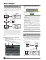
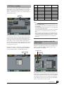
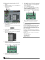
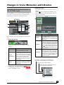
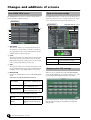
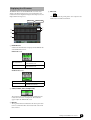
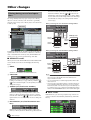
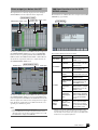
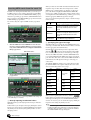
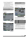
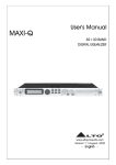
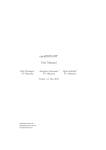
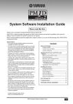
PM1D System Software Version 2
Supplementary Manual
This supplementary manual primarily describes the additional and modified functions that have been incorporated into PM1D System Software version 2.0.
Please read this manual in conjunction with the original manual that came with
your Yamaha PM1D digital audio mixing system.
Table of Contents
■ Main changes ..................................... 2
■ Other changes.................................. 10
Auto Gain Adjustment function ......................2
PM1D Manager Remote Control function ......2
VCM Effects available .....................................3
Channel Move function in the CH COPY
screen .........................................................3
Filtering during save or load operations ........10
Direct output just before the HPF ................ 11
Additional functions for the USER DEFINE
switches ................................................... 11
Inserting MIDI events from the event list ..... 12
CLEAR ALL button added to the OSCILLATOR
and TALKBACK screens............................. 13
Outputting the MONITOR and CUE signals
from the DSP1D ....................................... 13
No limitation in multiple selections for the
Global Paste function ............................... 14
Selecting WITH MIX SEND in the CH COPY
screen ...................................................... 14
Support for the MY8-DA96 card .................. 14
Compatibility of created data ...................... 14
■ Changes in Scene Memories and
Libraries.............................................. 5
Expanding the Event Recall function
in the TC EVENT screen...............................5
Overwriting libraries during the Auto Store
operation ....................................................6
Unit settings can be included in the Recall
Safe channel settings...................................7
Additional preset scenes .................................7
Expanded user area for Input EQ/Channel
libraries .......................................................7
■ Appendix .......................................... 15
■ Changes and additions of screens..... 8
Scene Memory Preset List ............................ 15
VCM Effect Parameter List............................ 18
New FADER VIEW screen ................................8
Clock on the meter bridge .............................8
Displaying the GEQ routings ..........................8
Displaying the GR meters ...............................9
EN
Main changes
Auto Gain Adjustment function
If you adjust the HA gain on the master CS1D (master for HA
control), the attenuation on a slave CS1D can automatically be
adjusted so that the channel output levels will remain
unchanged.
2. In the upper left of the screen, click the AUTO
GAIN ADJUSTMENT button to enable the function.
The Auto Gain Adjustment function is now enabled.
3. Turn the GAIN ADJ button on or off to switch the
function for each channel on or off.
Engine
DSP1D/
DSP1D-EX
Slave
Console CS1D
Note
Output B
AI8 (ID=1)
ANALOG OUTPUT BOX
Output A
Engine
DSP1D/
DSP1D-EX
CONTROL
PORT
A
B
C
Master
Console CS1D
The master unit is the CS1D (or PM1D Manager) connected
via a DSP1D that is connected to the port through which the
AI8 is controlled. The slave unit is the CS1D (or PM1D Manager) connected via a DSP1D that is connected to any port
other than the master. You can switch between the master and
slave.
■ Switching the Auto Gain Adjustment
function on and off
1. On the slave CS1D, display the ATT screen for the
IN EQ function.
AUTO GAIN ADJUSTMENT button
ATT
SET ALL and CLEAR ALL buttons
GAIN ADJ buttons
• Click the SET ALL button to turn on the function for all channels
globally. Click the CLEAR ALL button to turn off the function for
all channels globally.
• In most cases, turn on the Auto Gain Adjustment function only on
the slave CS1D unit. If you turn on the function on the master
CS1D unit, the output level of the master CS1D will also be
adjusted automatically.
• The GAIN ADJ button’s on/off status is not linked even if the corresponding two channels are paired. Even if the GAIN ADJ button of either one of the paired channels is turned on, the
attenuators will not be linked.
• When you turn off the GAIN ADJ button for one of the paired
channels, the attenuator value for the even-numbered channel
will change to the value for the odd-numbered channel. In this
case, please note that the volume level might increase more than
expected.
• If the attenuator values are selected as one of the Recall Safe
items, and if the GAIN ADJ button for the recalled scene is set to
on, this function will apply to the recalled HA gain. The Recall
Safe function does not apply to the GAIN ADJ button and AUTO
GAIN ADJUSTMENT button settings. Therefore, you must first
store these button settings in the scenes.
PM1D Manager Remote Control function
Connecting the PM1D Manager and a Yamaha digital mixing
console (DM2000, 02R96, or DM1000) via USB enables you to
remotely control the PM1D system from the digital mixing
console. For details, refer to the PM1D Manager V2 Owner's
Manual.
Yamaha digital mixer
(DM2000 V2, 02R96 V2,
DM1000 V2)
PM1D Manager
USB
USB/RS232C
PM1D system
Engine
DSP1D/DSP1D-EX
2
Main changes
Console CS1D
VCM Effects available
Value
Various effects sold as Add-On Effects packages for Yamaha
digital mixing consoles (such as DM2000) are now included as
standard. To use the VCM effects, you must first specify the
number of VCM effects you wish to use to limit the number of
available GEQ modules.
EFFECT
—
VCM effects
Available GEQ
EFFECT 1–8
GEQ 1–24
EFFECT 1
EFFECT 2–8
GEQ 1–22
1-2
EFFECT 1–2
EFFECT 3–8
GEQ 1–20
1-3
EFFECT 1–3
EFFECT 4–8
GEQ 1–18
1-4
EFFECT 1–4
EFFECT 5–8
GEQ 1–16
1-5
EFFECT 1–5
EFFECT 6–8
GEQ 1–14
1-6
EFFECT 1–6
EFFECT 7–8
GEQ 1–12
1-7
EFFECT 1–7
EFFECT 8
GEQ 1–10
1-8
EFFECT 1–8
1
—
Conventional
effects
—
GEQ 1–8
Note
The VCM effects employ Virtual Circuitry Modeling technology, and include compressors and EQs that model the characteristics of analog circuits, OpenDeck, which emulates tape
compression created by open reel tapes; and the REV-X reverb
effect, which is based on a newly-developed algorithm and
provides richly reverberant sound quality with smooth attenuation. For more information on the VCM effects, please refer
to the Appendix on page 18.
To use the VCM effects, you must first specify the number of
VCM effects you wish to use in the following DSP CONFIG
screen to limit the number of available GEQ modules.
• To use VCM effects on a single effect module, you must
disable two GEQ modules.
• If you change this setting, the effect and GEQ output will be temporarily muted.
• The disabled GEQ modules still enable you to control the parameters, but the output will be muted.
• You can recall these new effects in the same way as the existing
effects. That is, you recall the desired effects from the Effect
library.
• Please note that if you mix a signal processed with VCM effects
with a signal that utilizes a different routing, a difference in time
resulting from the different signal paths may cause a comb filter
effect (a phenomena in which the level of some frequencies
decreases).
Channel Move function in the CH
COPY screen
In addition to the CH Copy function in the CH COPY screen,
which copies channels globally, a CH Move function that
moves channels is now available.
CH MOVE button
DSP CONFIG
CH COPY
The CH Move function enables you to move any input or output channels to specified channel locations. When the channels
are moved, the channels between the move source and destination channels will move forward or backward accordingly. To
use the CH Move function, you can either use the CH COPY
screen or operate the keys on the top panel.
Main changes
3
■ Moving the channels in the CH COPY
screen
1. Display the CH COPY screen for the IN CH View or
OUT CH View function.
■ Moving the channels from the top panel
1. Press the [SEL] switches to select the input channels you wish to move.
2. Press the [CHANNEL COPY] key.
3. Hold down the [SHIFT] key and press the [SEL]
switch of the destination channels.
The CH DATA MOVING pop-up window appears, indicating the move source and destination channel numbers.
CH MOVE button
CH COPY
Move source channels
Move destination channels
4. Click the OK button to execute the function.
The channels are now moved to the new locations.
Note
2. In the CH COPY/CH MOVE section, turn on the
CH MOVE button.
If the CH COPY button is on, you can use the usual Channel Copy function.
3. Press the [SEL] switches to select the channels you
wish to move.
4. Select the destination channels in the DESTINATION CH SELECT section.
5. Click the EXECUTE button.
The CH DATA MOVING pop-up window appears, indicating the move source and destination channel numbers.
Move source channels
Move destination channels
6. Click the OK button to execute the function.
The channels are now moved to the new locations.
4
Main changes
• The move source channel can be a single channel or two
channels that can be paired.
• You can move a single channel under the following conditions:
There are no paired channels between the move source and
destination channels, AND all the following parameters are
turned off: HA GAIN GANG, HA A/B LINK, GATE LINK, COMP
LINK, DELAY GANG, GANG PAN/INV PAN/BALANCE in PAN
MODE, and M/S DECODE.
• If you move two channels, the first channel of the destination
channels will be the first of the two channels that can be paired.
Therefore, moving two channels will never swap between the left
and right channels.
• You can move the channels only within the following channel
sections:
– Input channels 1–96
– Stereo input channels 1–8
– MIX channels 1–48
– STEREO A/B channels
– MATRIX channels 1–24
Changes in Scene Memories and Libraries
Expanding the Event Recall function in
the TC EVENT screen
In the TC EVENT screen, you can now register scenes in the
order of use, so that these scenes can be recalled manually, or
automatically according to the specified interval time.
2 EVENT TRIGGER
This column indicates the way in which each event is
recalled.
Click the
button to display the TC EVENT pop-up
window, then click one of the following three buttons to
select the recall condition.
TC EVENT
1
3
2
4
5
Button
The TC EVENT screen features the following additional functions:
MANUAL
You can use the EVENT RECALL button
in the EVENT RECALL section (4) or a
USER DEFINE switch to recall the event.
“[MANUAL]” appears in the EVENT TRIGGER column.
INTERVAL
The scene will be recalled when the specified time has elapsed since the preceding
scene was recalled. If you select this button, specify the INTERVAL TIME parameter in the range of 0.1 through 999.9sec.
An “
” symbol and the interval time will
appear in the EVENT TRIGGER column
of the event list.
TIME CODE
The scene will be recalled when the time
code (LTC or internal time code) reaches
the specified time. If you select this button, specify the time code (hours/minutes/
seconds/frames). The specified time code
will appear in the EVENT TRIGGER column of the event list.
1 EVENT RECALLING
Use the following three buttons to switch the event list
operation.
Button
function
DISABLE
The Event List function will not recall
scenes registered in the event list.
ENABLE
[ALL MANUAL]
Scenes registered in the event list will
be recalled only by manual operation. If
the list contains events for which a time
code has been specified, the candidate
event for recall will change as time
code progresses, but events will not
actually be recalled unless you recall
them manually.
ENABLE
Scenes registered in the event list will
be recalled according to the specified
condition (time code, interval, or manual operation).
The upper part of the display will show
tor if ENABLE [ALL MANUAL] is selected, or
indicator if ENABLE is selected.
indica-
function
Event that is recalled when the specified time has
elapsed since the preceding scene was recalled
Event that will be recalled manually
Events that will be recalled when the time
code reaches the specified time
Changes in Scene Memories and Libraries
5
3 SCENE MEMORY
These are the number and title of the scene to be recalled.
Click the
button to display the TC EVENT pop-up
window, then click the number of a scene to select it.
Overwriting libraries during the Auto
Store operation
When you store scenes using the Auto Store function, you can
now select an unused library or the original library as the initial store destination.
DEFAULT EDIT LIBRARY NO.
Button
Function
DIRECT
Recalls the specified scene. Specify a
scene to recall in the section to the
right.
INC
Recalls the subsequent scene (registered just after the current scene).
DEC
Recalls the previous scene (registered
just before the current scene).
DISABLE
Recalls no scene.
DEFAULT EDIT LIBRARY NO.
4 EVENT RECALL
These functions enable you to recall events. The following
three buttons are provided.
Button
NEW
The lowest unused library numbers will be
selected. (This is the same as the previous software version.)
OVERWRITE
The number of the most-recently recalled
library will be selected. (If the scene was
specified as read-only, or if the corresponding library is write-protected, the
lowest-numbered unused library will be
selected.) This selection is useful when
you wish to prevent a particular library
from becoming full or lacking space during the Auto Store operation, or when you
wish to edit a particular library.
Function
PREV
When you click this button, the event preceding the last-recalled event in the list
will be recalled and selected.
DIRECT
When you click this button, the event currently selected in the event list will be
recalled.
NEXT
When you click this button, the event following the last-recalled event in the list
will be recalled and selected. This button
is useful when you recall an event that
has been assigned as “[MANUAL]” in the
EVENT TRIGGER column.
5 MOVE UP/MOVE DOWN
These buttons move the currently-selected event one position earlier (MOVE UP) or later (MOVE DOWN) in the
event list.
Note
• If the EVENT TRIGGER column of the selected event shows a
time code, these buttons will be grayed-out and unavailable. To
change the order of each event that displays a time code,
change the time code.
6
The following buttons are now available in the SCENE STORE
pop-up window that is displayed when you press the SCENE
MEMORY [STORE] switch (or the STORE button in the
MEMORY screen).
Changes in Scene Memories and Libraries
Note
• This setting is remembered when you close the pop-up
window.
Unit settings can be included in the
Recall Safe channel settings
You can globally apply the Recall Safe function to settings for
units that are patched to Recall Safe channels, as well as to the
Recall Safe channel settings themselves.
SAFE KEY MODE SELECT section
RECALL SAFE
Additional preset scenes
Factory-shipped preset scenes 00.0 – 00.9 in the scene memory
were reviewed and replaced with more practical scenes. For
details, please refer to the “Scene Memory Preset List” on
page 15.
Hint
• To use the preset scenes, follow the steps below:
1. Recall the desired preset scene.
2. In the INPUT PATCH screen, patch the input channels that
use the signals from the connected units. When you click the
AUTO SETUP button, the unit signals are patched from
Channel 1 in the order of the connected units.
3. In the OUTPUT PATCH screen, patch the buses to the signals of the connected units.
Note
• Please note that if you mix signals that have different paths, a
difference in the time taken via the different signal paths may
cause a comb filter effect (a phenomena in which the level of
some frequencies decreases).
Expanded user area for Input EQ/
Channel libraries
SAFE KEY MODE SELECT
CH
CH+UNIT
If you turn on or off the Recall Safe function for the selected channel from the
panel or in the IN CH VIEW screen, only
the Recall Safe function for the channel is
turned on or off. (This is the same as the
previous software version.)
The user area for the Input EQ library and Input Channel
libraries has been expanded.
• Input EQ library
#001 – 199 (#038 – 199 are the user area.)
• Input Channel library
#000 – 199 (#001 – 199 are the user area.)
If you turn on or off the Recall Safe function for the selected channel from the
panel or in the IN CH VIEW screen, the
Recall Safe function for both that channel
and the unit patched to the channel is
turned on or off.
Note
• Selecting the Recall Safe items using the SAFE [RECALL]
switch on the panel or the button in the IN CH VIEW screen
(when the CH+UNIT button is turned on) provides the same
result as turning on the SAFE ON/OFF button and UNIT button
on the screen (when the CH button is turned on).
• When the CH+UNIT button is turned on, the SAFE [RECALL]
switch on the panel or the button in the IN CH VIEW screen is
linked to the on/off operation of the SAFE ON/OFF and UNIT
buttons on the screen.
Changes in Scene Memories and Libraries
7
Changes and additions of screens
New FADER VIEW screen
Clock on the meter bridge
The FADER VIEW screen has been added to the IN CH View
function and OUT CH View function.
The TIME CODE indicator on the meter bridge block can now
display the current time. Also, an additional parameter enables
you to switch between the current time and time code.
FADER VIEW
PREFERENCE
TIME CODE DISPLAY section
4
1
2
3
1
2
3
1 ON/MUTE
These buttons enable you to switch the channels on/off,
and switch DCA group muting on/off. They are linked to
the [ON] switches of the corresponding channels and the
[MUTE] switches of the DCA groups.
2 Level
These buttons enable you to adjust the level of the channels
and DCA groups. The current value is shown in the box
immediately below. They are linked to the encoder or fader
of the corresponding channel or DCA group.
TIME CODE DISPLAY
PRESENT TIME
Displays the current time in 24-hour format (hours/minutes/seconds).
TIME CODE
Displays the time code.
3 CUE
These buttons enable you to switch cue monitoring on/off
for the channels and DCA groups. They are linked with the
[CUE] key of the corresponding channel or DCA group.
4 DISPLAY CH
Switches the channels that are shown in the FADER VIEW
screen.
Displaying the GEQ routings
When you select a GEQ module in the GEQ PARAMETER
screen, the GEQ SELECT pop-up window enables you to identify any GEQ modules that have already been patched.
• When you are using the IN CH View function:
INPUT [PANEL]
Channels specified via the Panel
Assign function, and DCA groups
1–12
CH 1-48/ST IN 1-4
Input channels 1–48, ST IN channels 1–4, DCA group 1–12
CH 49-96/ST IN 5-8
Input channels 49–96, ST IN
channel 5–8, DCA groups 1–12
• When you are using the OUT CH View function:
8
MIX 1-48
MIX channels 1–48, STEREO A/
B channels, DCA groups 1–12
MATRIX
MATRIX channels 1–24, STEREO A/B channels, DCA groups
1–12
Changes and additions of screens
This window displays the signal routing of already-patched
GEQ modules, and displays “NO ASSIGN” for unpatched
GEQ modules.
Displaying the GR meters
The INPUT GR screen and OUTPUT GR screen have been
added to the Meter function. These screens display the gain
reduction meters for Input channel gates and compressors, and
Output channel compressors.
INPUT GR
4 Pair icon
This icon indicates the pairing status of two adjacent oddnumbered/even-numbered channels.
OUTPUT GR
1
3
2
4
3
1 DISPLAY CH
Switches the channels that are displayed in the INPUT GR
and OUTPUT GR screens.
INPUT GR screen:
CH 1-48/ST IN 1-4
Input channels 1–48,
ST IN channels 1–4
CH 49-96/ST IN 5-8
Input channels 49–96,
ST IN channels 5–8
OUTPUT GR screen:
MIX 1-48
MIX channels 1–48
MATRIX 1-24/STEREO
MATRIX channels 1–24,
STEREO A/B channels
2 GATE/COMP (Gate/Compressor)
These buttons select whether the meters will display gain
reduction for the Gate or Compressor. These buttons
appear only in the INPUT GR screen.
3 Meters
These peak level meters indicate the amount of gain reduction for each channel. The current fader value is shown in
the box below.
Changes and additions of screens
9
Other changes
Filtering during save or load operations
You can specifically select any region of any scene or library
data to be saved to a memory card. You can also specifically
select any region of any scene or library data to be loaded from
a memory card.
be saved or loaded. If you want to change the save/load
destination numbers, click the [ ]/[ ] buttons at the
left and right of the starting number box or use the [DATA]
encoder. (The value in the ending number box will change
automatically according to the starting number and the
source range.)
When you change the save destination starting number:
LOAD/SAVE
1
CS1D
2
3
4
Memory card
Starting
number
Ending
number
01.0
01.1
01.2
01.3
01.4
01.5
AAA
BBB
CCC
DDD
EEE
FFF
Starting
number
SAVE
SOURCE
In addition to BASIC mode (in which you can save the entire or
specified data in the scene memories or libraries to a memory
card, or load them from a memory card), ADVANCED mode
enables you to save or load a specified range of the data.
02.0
02.1
02.2
02.3
02.4
AAA
BBB
CCC
DDD
EEE
DESTINATION
When you change the load destination starting number:
CS1D
■ ADVANCED mode:
When you turn on the ADVANCED button in the LOAD/SAVE
screen, the left side of the screen will display the following
items:
1 MODE
Memory card
Starting
number
Ending
number
02.1
02.2
02.3
02.4
02.5
BBB
CCC
DDD
EEE
FFF
Starting
number
LOAD
Switches between BASIC and ADVANCED mode.
2 CATEGORY
Indicates the category of data that is selected for saving or
loading: scene memory or a type of library. Click the [ ]/
[ ] buttons at left and right or use the [DATA] encoder to
change the category.
3 SOURCE (save/load source numbers)
Indicates the starting and ending numbers of the scene
memory or library items that will be saved to or loaded
from the card. Click the [ ]/[ ] buttons at the left and
right in each box or use the [DATA] encoder to change the
numbers.
4 DESTINATION (save/load destination numbers)
Indicates the starting and ending numbers of the scene
memory or library items into which the specified data will
10
Other changes
SOURCE
02.5
02.6
02.7
02.8
BBB
CCC
DDD
EEE
DESTINATION
Note
• To format a memory card first, use a computer or other external
device and select the FAT16 format. The CS1D does not
support the FAT 32 format.
• You can load the data you saved using System Software older
than version 2.0.
• The preset effects in the Effects library of System Software version 2.0 includes VCM effects. Therefore, if you try to load the
Effects library data of an older version, part of the data may not
be loaded. In such a case, change the load destination starting
number in the DESTINATION section, then load the data again.
■ BASIC mode:
In BASIC mode, you can now specify the range of data to be
saved or loaded for the Unit library, Patch library, and Name
library.
Direct output just before the HPF
The signal can be now directly output just before the Input
channel HPF. You can also adjust the direct output level.
INSERT/DIRECT POINT
DIRECT OUT LEVEL column
DIRECT OUT POINT column
PRE HPF button
To select a position just before the HPF as the direct output on
the INSERT/DIRECT POINT screen, turn on the PRE HPF
button for the corresponding channels in the DIRECT OUT
POINT column. The DIRECT OUT LEVEL column will indicate the direct output levels. However, to adjust the level, use
the INSERT/DIRECT VIEW screen.
DIRECT button
INSERT/DIRECT VIEW
LEVEL knob
Additional functions for the USER
DEFINE switches
More functions are available that can be assigned to the USER
DEFINED [1]–[8] switches.
USER DEFINE
The following functions have been added:
FUNCTION
GEQ SELECT
PARAMETER
GEQ1–24
Display the GEQ PARAMETER screen.
CURRENT
Uses the Tap Tempo function available on the displayed screen.
EFFECT1–8
Uses the Tap Tempo function available for the
specified effect.
NEXT EVENT
RECALL
Recalls the subsequently-numbered event.
PREV EVENT
RECALL
Recalls the previouslynumbered event.
DIRECT EVENT
RECALL
Recalls the specified
event registered on the
TC EVENT screen.
ENABLE/DISABLE
Switches between the
ENABLE button and DISABLE button on the TC
EVENT screen.
ENABLE[ALL
MANUAL]/DISABLE
Switches between the
ENABLE [ALL MANUAL]
button and DISABLE button on the TC EVENT
screen.
MIX 1–48,
MATRIX 1–24,
STEREO,
MONITOR B
Send the talkback signal
to the specified output
channels. (If you turn it
off, the previous talkback
setting will be used.)
TAP TEMPO*
TC EVENT
To select a position just before the HPF as the direct output in
the INSERT/DIRECT VIEW screen, turn on the DIRECT button located just before the HPF. Use the LEVEL knob located in
the lower right corner of the screen to change the direct output
level. The direct output levels are not linked even if the corresponding two channels are paired.
Hint
• These settings are saved in scene memories.
• If you load data that was saved in a System Software version
older than version 2.0, the direct output level will be set to 0 dB.
The default direct output point is PRE EQ.
TALKBACK
DIRECT
ASSIGN
Explanation
* This function is enabled only when an effect that features the TEMPO
parameter is selected. The USER DEFINE switch LED flashes at the
specified tempo while and after you set the tempo. For more information
on the Tap Tempo function, please refer to page 51 of the PM1D System
Software Version 1.5 Supplementary Manual.
Other changes
11
Inserting MIDI events from the event list
In addition to entering hexadecimal values, you can also specify MIDI events for scene recall by entering the desired MIDI
events using the list in the new MIDI EVENT SETUP pop-up
window. To open this pop-up window, a MIDI EVENT button
has been added to the SCENE STORE pop-up window and the
SCENE TITLE pop-up window.
You can also delay the output of MIDI events by a specified
time.
When you click a box in which a hexadecimal value has been
input, the range of values that can be interpreted as a valid
MIDI message (including that box) will turn red. The lower
part of the window displays the MIDI channel (MIDI CH),
message type (TYPE), and data values (DATA 1, DATA 2) that
are interpreted from this MIDI message, enabling you to verify
that the appropriate MIDI message has been input.
You can use the following buttons to input or edit the message
in this window.
[
]/[
]buttons
Move the highlighted area to left or right.
INS button
Inserts a space (blank) at the highlighted
position. Pressing the <Insert> key on a
PS/2 keyboard will produce the same
result.
DEL button
Deletes the character at the highlighted
position. Pressing the <Delete> key on a
PS/2 keyboard will produce the same
result.
CLEAR button
Erases the entire message that was input
in the MIDI message input boxes.
2 Specifying the type of message
1.
Click the STORE button on the MEMORY screen for the Scene
function to display the SCENE STORE pop-up window. Alternatively, click the TITLE EDIT button to display the SCENE TITLE
EDIT pop-up window.
MIDI EVENT button
With this method, you specify the desired MIDI channel, type
of message, and data value. This information will be converted
into the appropriate hexadecimal values.
Click the first box into which you want to input data. Next,
click the [ ]/[ ] buttons at the left and right of the TYPE
box or use the [DATA] encoder to select the type of message.
Then use the MIDI CH, DATA 1, DATA 2, MIDI PORT boxes
to specify the MIDI channel, MIDI event settings, and output
port. The values that can be selected in the MIDI CH, DATA 1,
and DATA 2 boxes will depend on the type of message you
selected first.
The DELAY TIME box enables you to set the amount of time
by which the MIDI event output is delayed after scene recall.
You can set this delay time in 0.1 sec steps.
TYPE
MIDI CH
DATA 1
DATA 2
Note-off velocity
(0 –-127)
NOTE OFF
2.
Click the MIDI EVENT button to open the MIDI EVENT SETUP
pop-up window.
Note number
(0–127)
NOTE ON
Pressure value
(0–127)
KEY PRESSURE
CONTROL
CHANGE
1 Directly inputting hexadecimal values
With this method, you directly input the message as hexadecimal values.
In this window, you can input a message by clicking the desired
input box to select it (the box will be highlighted) and rotating
the [DATA] encoder. Use the [INC]/[DEC] switches to move
the input position.
12
Other changes
1–16
Control number
(0–127)
Controller value
(0–127)
PROGRAM
CHANGE
Program number
(0–127)
—
CHANNEL
PRESSURE
Pressure value
(0–127)
—
PITCH BEND
Pitch bend MSB
(0–127)
EXCLUSIVE
MASSAGE
In this pop-up window, you can assign MIDI events using one
of the following two methods:
Note-on velocity
(0–127)
Pitch bend LSB
(0–127)
—
When you have specified all of the values, click the “
”
button in the screen. The hexadecimal values for that message
will be input in the input box of the MIDI EVENT SETUP
window. As necessary, you can edit the message by clicking an
input box and rotating the [DATA] encoder.
Note
• The maximum length of MIDI events you can enter is 32 bytes,
including the MIDI output destination port and other data and
comments. When the number of bytes exceeds the maximum,
the “LENGTH OVER!” message will appear.
• You can follow the steps below to set the DELAY TIME using the
SCENE STORE (or SCENE TITLE EDIT) pop-up window.
1. Move the cursor to the COMMENT/MIDI EVENT section,
then click the EVENT CODE SET button.
2. Click T and numbers 0-9 on the character palette to specify
the two-digit delay time in 100 msec steps. For example, if
you wish to delay the MIDI event output from scene recall by
500 msec, enter “T05.” You do not need to enter a value if you
do not want to delay the event output.
3. Click 1, 2 (Console 1 or 2), or E (Engine) on the character
palette to configure a MIDI port to output MIDI events.
Outputting the MONITOR and CUE
signals from the DSP1D
The DSP1D OUTPUT 6 connector can now output MONITOR A/B and CUE signals. This is convenient when you use
the PM1D Manager’s remote control function for the monitor/
cue operation.
SYSTEM CONNECTION
MONITOR / CUE OUTPUT
TO #6 button
CLEAR ALL button added to the
OSCILLATOR and TALKBACK screens
The OSCILLATOR and TALKBACK screens now feature a
CLEAR ALL button that cancels all assignments to the buses.
OSCILLATOR
When you turn on the MONITOR/CUE OUTPUT TO #6 button in the SYSTEM CONNECTION screen, the MONITOR A/
B and CUE 1/2 signals are output to the device connected to
the DSP1D’s OUTPUT 6 connector (channels 25-32). The following signals are output to the specified channels:
TALKBACK
Channel number
Output signal
25/26
MONITOR A L/R
27/28
MONITOR B L/R
29/30
CUE 1 L/R (Console 1 CUE signals)
31/32
CUE 2 L/R (Console 2 CUE signals)
Note
• Even if you have set the output patch, when the MONITOR/
CUE OUTPUT TO #6 is turned on, the MONITOR/CUE signals
will have priority and will be output.
• The MONITOR/CUE signal output to the unit is the same as the
signal output from the engine to the console. The TALKBACK
DIMMER, CUE INTERRUPT, ON/OFF, and LEVEL controls on
the console are ineffective for the signals output from the unit.
Therefore, the meter indication does not necessarily reflect the
level of the output signals. For details on the signals output from
the engine, refer to the PM1D System Block Diagram.
Other changes
13
No limitation in multiple selections for
the Global Paste function
In the previous software version, the Global Paste function
enabled you to select up to 100 scenes at a time. However, this
limitation has been removed. However, if you select 101 or
more scenes to paste, you will not be able to use the Undo
function. In this case, back up all important data using the
Select All function, then execute the Global Paste function.
Selecting WITH MIX SEND in the CH
COPY screen
In the previous software version, you could select WITH MIX
SEND only when the ALL parameter was selected in the CH
COPY screen for the Output CH View function. In the version
2.0 software, you can select WITH MIX SEND even if ALL is
not selected.
Support for the MY8-DA96 card
The MY8-DA96 card is now supported, and you can display
and edit the contents of the card using the CS1D or PM1D
Manager.
Compatibility of created data
Any data created in System Software version 2.0 (such as
scenes, libraries, setup data, etc.) cannot be loaded to a unit
that runs System Software version 1 (i.e., all versions prior to
version 2.0). However, any data created in System Software version 1 can be loaded to a unit that runs System Software version 2.0.
14
Other changes
Appendix
Scene Memory Preset List
Scene #
Title
00.1
Front of House
This front of house preset scene is designed by a famous American
front of house engineer. It features preset parameter values for the output channels, including Front Fill, Delayed Speaker, as well as Stereo
Mix Send to the internal effects.
INPUT CH1-96
EQ ON, TO STEREO ON, MIX SEND ON, CH ON
STEREO INPUT1-8: Internal EFFECT RETURN
TO STEREO ON, CH ON
MIX1-16: Internal EFFECT SEND
PAIR ON, MIX ON, LEVEL 0 dB
MIX17-18: Stereo Sub Feed
PAIR ON, MIX ON, LEVEL 0 dB, GEQ INSERT, INSERT ON
STEREO A-B
Scene #
Title
00.3
FoH & Mon
This preset covers the front of house and monitor on a single console.
The latter half of the mix is regarded as the monitor send, and the GEQ
is inserted for Wedge monitoring. This preset setting emulates Front
Fill and Delayed Speaker, with Matrix output.
INPUT CH1-96
EQ ON, TO STEREO ON, MIX SEND ON, CH ON
STEREO INPUT1-8: Internal EFFECT RETURN
TO STEREO ON, CH ON
MIX1-16: Internal EFFECT SEND
PAIR ON, MIX ON, LEVEL 0 dB
MIX17-18: Stereo Sub Feed
PAIR ON, MIX ON, LEVEL –∞ dB, GEQ INSERT, INSERT ON
MIX25-36: In Ear Monitor
PAIR ON, EQ ON, COMP ON —THR: 0 dB—RATIO: ∞: 1—
KNEE: HARD, MIX ON, LEVEL 0 dB
MIX37-48: Wedge Mix
STEREO ON, LEVEL 0 dB, GEQ INSERT, INSERT ON
MATRIX1-12: Front Fill Speaker, Delay Speaker, Rec Out
MATRIX ON, LEVEL –∞ dB, GEQ INSERT, INSERT ON (MATRIX1-6)
GEQ1-12
GEQ INSERT, INSERT ON, MIX ON, LEVEL 0 dB
STEREO A-B
STEREO ON, LEVEL 0 dB, GEQ INSERT, INSERT ON
MATRIX1-12: Front Fill Speaker, Delay Speaker, Rec Out
GEQ ON, LINK ON
PAIR ON, MATRIX ON, GEQ INSERT, INSERT ON (MATRIX1-6)
GEQ1-24
Scene #
Title
00.2
Monitor
GEQ ON, LINK ON (GEQ1-12)
This monitor mix preset scene is designed by a famous American monitor engineer. MIX 1-20 feature the inserted GEQ as Wedge monitoring; MIX 25-44 emulate 10-channel in-ear monitoring. Four effects are
assigned to each monitoring path. The stereo output is designed as
Side Fill, featuring the inserted GEQ.
INPUT CH1-96
HPF ON—F: 50 Hz—SLOPE: 18 dB, EQ ON, MIX SEND ON—
PRE FADER, TO STEREO ON, CH ON
STEREO INPUT1-8: Internal EFFECT RETURN
HPF ON—F: 50 Hz—SLOPE: 18 dB, EQ ON, MIX SEND ON – PRE
FADER (If a signal sent to a Mix bus causes an internal feedback loop,
the corresponding MIX SEND will be turned off.), TO STEREO ON
(STEREO INPUT 1, 2, 5, 6), CH ON
MIX1-20: Wedge Mix
GEQ INSERT, INSERT ON, MIX ON, LEVEL 0 dB
MIX21-24: Internal EFFECT1-4 SEND
MIX ON, LEVEL 0 dB
MIX25-44: In Ear Monitor
PAIR ON, EQ ON, COMP ON—THR: 0 dB—RATIO: ∞: 1—
ATTACK: 0 msec—KNEE: HARD, MIX ON, LEVEL 0 dB
MIX45-48: Internal EFFECT5-8 SEND
MIX ON, LEVEL 0 dB
STEREO A-B: Side Fill Mix
GEQ INSERT, INSERT ON, LEVEL 0 dB
GEQ1-24
GEQ ON, LINK ON (GEQ21-24)
Appendix
15
Scene #
Title
Scene #
Title
00.4
In Ear Monitor
00.6
OB Truck
This preset simulates an in-ear monitoring mix. It is a highly practical
preset, typical of the PM1D, with in-ear monitor and Wedge monitor
categorized into Output DCA for emergency use.
INPUT CH1-96
ATT: –10 dB, HPF ON—F: 50 Hz—SLOPE: 18 dB, EQ ON, COMP ON,
TO STEREO ON, MIX SEND ON, VARI PAN LINK ON, FIXED MIX
PAN ON, CH ON, LEVEL 0 dB
STEREO INPUT1-8: Internal EFFECT RETURN, 2-track Input
ATT: –10 dB, HPF ON—F: 50 Hz—SLOPE: 18 dB, EQ ON, COMP ON,
TO STEREO ON, MIX SEND ON, VARI PAN LINK ON, FIXED MIX
PAN ON, PAN MODE: BALANCE, CH ON
MIX1-24: In Ear Monitor
PAIR ON, EQ ON, DCA 11 ASSAIGN, MIX ON, LEVEL 0 dB
MIX25-36: Wedge Mix
GEQ INSERT, INSERT ON, DCA12 ASSIGN, MIX ON, LEVEL 0 dB
MIX45-48: Internal EFFECT SEND
EQ ON, DCA9 ASSIGN, MIX ON, LEVEL 0 dB
STEREO A-B
EQ ON, LEVEL 0 dB
GEQ1-24
GEQ ON, LINK ON (GEQ1-12)
This preset simulates a scene for an outside broadcasting truck or van.
It features the HPF setting that is very practical for broadcasting application, and a MIX send setting that will simulate both internal and
external effect sends.
INPUT CH1-96
HPF ON—F: 95 Hz—SLOPE: 18 dB, EQ ON, COMP ON, MIX1-12
SEND ON, FIXED MIX PAN ON, CH ON
STEREO INPUT1-8: Playback, Internal EFFECT RETURN
MIX1-12 SEND ON (STIN1-4), FIXED MIX PAN ON, CH ON
MIX1-4: Internal EFFECT SEND
MIX ON, LEVEL 0 dB
MIX5-12: External EFFECT SEND
PAIR ON (MIX5-8), MIX ON, LEVEL 0 dB
MIX37-48: Wireless Camera Mix, Playback Mix, Mic Mix, etc.
FIX, INSERT ON (MIX45-48), PAIR ON (MIX45-48), DELAY ON—
86 msec@fs=48 kHz (MIX41), DCA11 ASSIGN (MIX45-46), DCA12
ASSIGN (MIX41, 47-48), TO STEREO ON (MIX41, 45-48), MIX ON
(MIX41, 45-48), LEVEL 0 dB (MIX41, 45-48)
STEREO A-B
INSERT ON—POST ON, TO MATRIX ON—MATRIX1-2 SEND LEVEL:
0 dB—MATRIX3 SEND LEVEL:–3.1 dB (STEREO A L/R), STEREO
ON, LEVEL 0 dB
DCA9, 11-12
DCA LEVEL 0 dB
MATRIX1-3
PAIR ON (MATRIX1-2), MATRIX ON, LEVEL 0 dB
EFFECT1-8
Scene #
Title
00.5
Musical
EFFECT1: MIX1, EFFECT2: MIX2, EFFECT3: MIX3, EFFECT4: MIX4,
EFFECT5: MIX45-46, EFFECT6: MIX47-48, EFFECT7: STEREO B L/
R, EFFECT8: STEREO A L/R, EFFECT5-8: MULTI BAND DYNA.
DCA11-12
This preset simulates a musical mix scene. MIX1-12 are set to Fix, and
are designed to be used as buses.
INPUT CH1-96
ATT: –3 dB, INSERT OFF—PRE DELAY, EQ ON, TO STEREO ON,
FIXED MIX PAN ON
STEREO INPUT1-8: Internal EFFECT RETURN, 2-track Input
EQ ON, FIXED MIX PAN ON
MIX1-12
FIX, PAIR ON (MIX5-6,11-12), EQ ON, TO MATRIX ON—LEVEL: 0 dB
(Even-numbered MIX bus sends from MIX 5 and 11, and odd-numbered MIX bus sends from MIX 6 and 12 are set to –∞ dB.), MIX ON,
LEVEL 0 dB
MIX13-48: Internal EFFECT SEND, etc.
VARI, PAIR ON (MIX13-24), EQ ON, DCA12 ASSIGN (MIX13-22),
DCA10 ASSIGN (MIX25-26), DCA11 ASSIGN (MIX33-35), MIX ON,
LEVEL 0 dB
STEREO A-B
EQ ON
MATRIX1-24
EQ ON, MATRIX ON, LEVEL 0 dB
EFFECT1-8
EFFECT1: MIX25, EFFECT2: MIX26, EFFECT3: MIX27, EFFECT5:
MIX33, EFFECT6: MIX34, EFFECT7: MIX35, EFFECT8: MIX36
16
Appendix
DCA LEVEL 0 dB
Scene #
Title
Scene #
Title
00.7
Theatre
00.9
Live Recording
This preset simulates a theatrical mix scene. It features the default settings for L-C-R panning.
INPUT CH1-96
HPF OFF—F: 20 Hz, EQ ON, LCR ON, CH ON
STEREO INPUT1-8: Internal EFFECT RETURN, etc.
This preset simulates a live recording application. MIX1-48 are set to
Fix, and sent to the recorder. Each channel’s direct out also features
settings appropriate for recording.
INPUT CH1-96
DIRECT OUT POST ON, HPF OFF - SLOPE: 12 dB, EQ ON, TO STEREO ON, CH ON
HPF OFF—F: 20 Hz, EQ ON, LCR ON, CH ON
STEREO INPUT1-8: Internal EFFECT RETURN, etc.
MIX1-12: Stage Mix, Monitor Mix, etc.
FIX (MIX1-4), EQ ON, DELAY ON —0.00 msec, MIX ON (MIX1-8),
LEVEL 0 dB (MIX1-8)
DIRECT OUT POST ON, HPF OFF—SLOPE: 12 dB, EQ ON, TO STEREO ON, CH ON
MIX1-48: Recording Mix
MIX13-48: Internal EFFECT SEND, etc.
PAIR ON (MIX13-20), EQ ON, DELAY ON—0.00 msec (MIX25-48),
MIX ON (MIX13-20,25-48), LEVEL 0 dB (MIX13-20)
FIX, TO MATRIX ON—PRE FADER, MIX ON, LEVEL 0 dB
STEREO A-B
STEREO ON
STEREO A-B
LCR CENTER BUS CONTROL ON, EQ ON, TO MATRIX ON (STEREO A L/R), STEREO ON, LEVEL 0 dB
MATRIX1-24: Delay Mix, etc.
PAIR ON (MATRIX1-8), EQ ON, DELAY ON—0.00 msec, MATRIX ON,
LEVEL 0 dB (MATRIX1-12)
EFFECT1-8
MATRIX1-4: Internal EFFECT SEND
MATRIX ON, LEVEL 0 dB
EFFECT1-8
EFFECT1: MATRIX1, EFFECT2: MATRIX2, EFFECT3: MATRIX3,
EFFECT4: MATRIX4
DCA1-12
EFFECT1: MIX13-14, EFFECT2: MIX15-16, EFFECT3: MIX17-18,
EFFECT4: MIX19-20
Scene #
Title
00.8
Broadcast
DCA LEVEL 0 dB
This preset simulates a broadcasting application. It includes input
channel EQ and Comp settings that are typical to broadcasting, as well
as multiple sends.
INPUT CH1-24: Radio Lapel Mic
EQ ON—LOW TYPE: SHELF—LOW F: 71 Hz—LOW G: –3 dB—HIGH
MID Q: 0.90—G: +4 dB, COMP ON—THR:—18 dB—RATIO: 3.5: 1,
DCA1 ASSIGN (CH13), DCA2 ASSIGN (CH14), DCA3 ASSIGN
(CH15), DCA4 ASSIGN (CH16), DCA5 ASSIGN (CH17), DCA6
ASSIGN (CH18), DCA7 ASSIGN (CH19), DCA8 ASSIGN (CH20),
DCA9 ASSIGN (CH21), DCA10 ASSIGN (CH22), DCA11 ASSIGN
(CH23), DCA12 ASSIGN (CH24), TO STEREO ON, FIXED MIX PAN
ON, CH ON
INPUT CH25-96
HPF OFF—SLOPE: 12 dB, EQ ON, FIXED MIX PAN ON, CH ON,
LEVEL 0 dB
STEREO INPUT1-8: Internal EFFECT RETURN, Playback
TO STEREO ON, FIXED MIX PAN ON, CH ON
MIX1-16: Recording Mix
MIX ON, LEVEL 0 dB
MIX21-24: Internal EFFECT SEND
MIX ON, LEVEL 0 dB
MIX25-48: Sub Group
FIX, PAIR ON, TO STEREO ON, MIX ON, LEVEL 0 dB
STEREO A-B
COMP ON—THR:–18 dB (STEREO A), STEREO ON
EFFECT1-8
EFFECT1: MIX21, EFFECT2: MIX22, EFFECT3: MIX23, EFFECT4:
MIX24
DCA1-12
DCA LEVEL 0 dB
Appendix
17
VCM Effect Parameter List
072: REV-X HALL, 073: REV-X ROOM,
074: REV-X PLATE
These effects are a newly-developed 2-in/2-out reverb algorithm. They
provide a high-density, richly reverberant sound quality, with smooth
attenuation, spread and depth that work together to enhance the original
sound. You can choose one of three programs to suit the acoustic sound
field and your intentions: REV-X Hall, REV-X Room, and REV-X Plate.
Parameter
REV TIME
Range
0.47–46.92 s *1
Description
Delay time until early reflection is
heard
0.1–1.0
The reverberation duration of the
high frequency range is expressed
as a ratio relative to REV TIME.
LO. RATIO
0.1–1.4
The reverberation duration of the low
frequency range is expressed as a
ratio relative to REV TIME.
LO. FREQ
22.0 Hz–18.0 kHz Reference frequency of LO. RATIO
DIFF.
0–10
HI. RATIO
This effect emulates the characteristics of analog compressors that are
widely used in recording studios. It produces a thick, strong frame
sound suitable for drums and bass. You can link and control the L and
R channel parameters.
Parameter
Range
Description
INPUT
–180 to 0 dB
Adjusts the input level
OUTPUT
–180 to 0 dB
Adjusts the output gain
RATIO
1:2, 4:1, 8:1, 12:1,
20:1
Ratio of the compressor
ATTACK
0.022–50.4 ms
Attack time of the compressor
RELEASE
10.88–544.22 ms
Release time of the compressor
MAKE UP
OFF, ON
Automatically corrects output gain
reduction when the compressor is
applied
OFF, ON
When the HPF in the side chain of
the compressor is turned on, the
compression applied to the low
range will be weakened, thus
emphasizing the low range.
Length of reverberation
0.0–125.0 ms
INI. DLY
076: COMP276S
SIDE HPF
Left and right directional spread of
reverb sound
ROOMSIZE
0–28
Size of space
077: COMP260
DECAY
0–53
Speed at which the gate closes
HPF
THRU, 22.0 Hz–
8.00 kHz
Cut-off frequency for the high pass
filter
LPF
1.00 kHz–
18.0 kHz, THRU
Cut-off frequency for the low pass filter
This effect emulates the characteristics of mid 70’s compressors/limiters that are the standard for live SR. You can control two monaural
channels independently. You can also link several parameters via stereo
links.
*1. This value applies only when the effect type is REV-X PLATE, with
ROOM SIZE set to 28. The setting range varies depending on the
effect type and the ROOM SIZE value.
Parameter
Range
Description
THRE.1
–60 to 0.0 dB
Threshold of CH compressor
KNEE1
SOFT, MEDIUM,
HARD
Knee of CH1 compressor
075: COMP276
ATTACK1
0.01–80.0 ms
Attack time of CH1 compressor
This effect emulates the characteristics of analog compressors that are
widely used in recording studios. It will produce a thick, strong frame
sound suitable for drums and bass. You can control two monaural
channels independently.
RELEASE1
6.2–999 ms
Release time of CH1 compressor
RATIO1
1.0–500, ∞
Ratio of CH1 compressor
OUTPUT1
–20 to 40 dB
Adjusts the CH1 output gain
THRE.2
–60 to 0.0 dB
Threshold of CH2 compressor
KNEE2
SOFT, MEDIUM,
HARD
Knee of CH2 compressor
Parameter
Range
Description
–180 to 0 dB
Adjusts the CH1 input level
OUTPUT 1
–180 to 0 dB
Adjusts the CH1 output gain
ATTACK2
0.01–80.0 ms
Attack time of CH2 compressor
RATIO 1
2:1, 4:1, 8:1, 12:1,
20:1
Ratio for CH1 compressor
RELEASE2
6.2–999 ms
Release time of CH2 compressor
ATTACK 1
0.022–50.4 ms
Attack time for CH1 compressor
RATIO2
1.0–500, ∞
Ratio of CH2 compressor
RELEASE1
10.88–544.22 ms
Release time for CH1 compressor
OUTPUT2
–20 to 40 dB
Adjusts the CH2 output gain
OFF, ON
Links CH1 and CH2 as a stereo pair.
THRE., KNEE, ATTACK, RELEASE,
and RATIO parameters are linked;
OUTPUT parameter is not linked
INPUT 1
OFF, ON
Automatically corrects output gain
reduction when CH1 compressor is
applied
SIDEHPF1
OFF, ON
When the HPF in the side chain of the
CH1 compressor is turned on, the
compression applied to the low range
will be weakened, thus emphasizing
the low range.
INPUT 2
–180 to 0 dB
Adjusts the CH2 input level
OUTPUT 2
–180 to 0 dB
Adjusts the CH2 output gain
RATIO 2
2:1, 4:1, 8:1, 12:1,
20:1
Ratio of CH2 compressor
ATTACK 2
0.022–50.4 ms
Attack time of CH2 compressor
RELEASE2
10.88–544.22 ms
Release time of CH2 compressor
MAKE UP2
OFF, ON
Automatically corrects output gain
reduction when the CH2 compressor
is applied
OFF, ON
When the HPF in the side chain of the
CH2 compressor is turned on, the
compression applied to the low range
will be weakened, thus emphasizing
the low range.
MAKE UP1
SIDEHPF2
18
Appendix
ST LINK
078: COMP260S
080: OPENDECK
This effect emulates the characteristics of mid 70’s compressors/limiters that are the standard for live SR. You can link and control the L and
R channel parameters.
It emulates the tape compression created by two open reel tape recorders (a recording deck and a playback deck.) You can change the sound
quality by adjusting various elements, such as the deck type, tape quality, playback speed, etc.
Parameter
THRE.
Range
–60 to 0.0 dB
Description
Threshold of the compressor
KNEE
SOFT, MEDIUM,
HARD
Knee of the compressor
ATTACK
0.01–80.0 ms
Attack time of the compressor
RELEASE
6.2–999 ms
Release time of the compressor
RATIO
1.0–500, ∞
Ratio of the compressor
OUTPUT
–20 to 40 dB
Adjusts the output gain
079: EQUALIZER601
This effect emulates the characteristics of 70’s analog equalizers. Recreating the distortion of typical analog circuits will add drive to the
sound.
Parameter
Range
Parameter
Range
Description
REC DEC
Swss70, Swss78,
Swss85, Amer70
REC LVL
Adjusts the input level of the recording deck. As you raise the level, tape
–96.0 to +18.0 dB compression is generated, which
narrows the dynamic range and distorts the sound
REC HI
–6.0 to +6.0 dB
Adjusts the high range gain of the
recording deck
REC BIAS
–1.00 to +1.00
Adjusts the bias of the recording
deck
REPR DEC
Swss70, Swss78,
Swss85, Amer70
Selects the playback deck type
REPR LVL
–96.0 to +18.0 dB
Adjusts the output level of the playback deck
Description
Selects the recording deck type
LO TYPE
HPF-2/1, LSH-1/2 Type of EQ1
REPR HI
–6.0 to +6.0 dB
Adjusts the high range gain of the playback deck
LO F
16.0 Hz to
20.0 kHz
REPR LO
–6.0 to +6.0 dB
Adjusts the low range gain of the playback deck
LO G
–18.0 to +18.0 dB Gain of EQ1
MID1 Q
0.50–16.0
MID1 F
16.0 Hz to 20.0 kHz Center frequency of EQ2
MAKE UP
Off, On
MID1 G
–18.0 to +18.0 dB Gain of EQ2
When you adjust the REC LVL, the
REPR LVL reflects the change,
maintaining the relative output level.
You can change the amount of distortion without changing the output
level.
Cut-off frequency of EQ1
Q of EQ2
MID2 Q
0.50–16.0
MID2 F
16.0 Hz to 20.0 kHz Center frequency of EQ3
Q of EQ3
TP SPEED
15ips, 30ips
Selects the tape speed
MID2 G
–18.0 to +18.0 dB Gain of EQ3
TP KIND
Old, New
Selects the tape type
INPUT
–18.0 to +18.0 dB Input gain
OUTPUT
–18.0 to +18.0 dB Output gain
MID3 Q
0.50–16.0
MID3 F
16.0 Hz to 20.0 kHz Center frequency of EQ4
MID3 G
–18.0 to +18.0 dB Gain of EQ4
Q of EQ4
MID4 Q
0.50–16.0
MID4 F
16.0 Hz to 20.0 kHz Center frequency of EQ5
Q of EQ5
MID4 G
–18.0 to +18.0 dB Gain of EQ5
HI TYPE
LPF-2/1, HSH-1/2 Type of EQ6
HI F
16.0 Hz to
20.0 kHz *1
HI G
–18.0 to +18.0 dB Gain of EQ6
LO SW
OFF, ON
Switches EQ1 on/off
MID1 SW
OFF, ON
Switches EQ2 on/off
MID2 SW
OFF, ON
Switches EQ3 on/off
MID3 SW
OFF, ON
Switches EQ4 on/off
Cut-off frequency of EQ6
MID4 SW
OFF, ON
Switches EQ5 on/off
HI SW
OFF, ON
Switches EQ6 on/off
CLEAN, DRIVE
Selects the equalizer type. The
CLEAN equalizer provides non-distorted, clear, typical digital sound,
emulating variations in frequency
response in the analog circuits. The
DRIVE equalizer provides distorted,
driven sound that enhances analog
flavor, emulating changes in frequency response in the analog circuits.
TYPE
*1. 16.0 Hz to 20.0 kHz (LPF-1, LPF-2), 1.0 kHz to 20.0 kHz (HSH-1, HSH-2)
Appendix
19
U.R.G., Pro Audio & Digital Musical Instrument Division, Yamaha Corporation
© 2005 Yamaha Corporation
WF52680 406IPAPx.x-01A0
Printed in Japan
A/B
AD
HA
CH 1 B
GAIN
CH 2 A
to OUTPUT PATCH
INSERT OUT 1(-48) (-96)
PEAK
METER
to METER
HA
CH 2 B
GAIN
[AI8 + LMY2-ML]
CH 1
BA
METER
to METER
CH 2
BA
HPF
DIGITAL
GAIN
KEY IN HPF LPF
SEL
AES/EBU
DIGITAL
GAIN
KEY IN4
CUE L
CUE R
KEY IN1
STEREO L
STEREO R
VARI
DE-EMPHASIS
DIRECT OUT STIN 1(-4) Lch
to OUTPUT PATCH (-8)
from PRE ATT.
from PRE EQ
CUE
METER
...
INSERT
MONO
METER
METER
6BAND
PEQ
COMP
CUE
Rch
4BAND
PEQ
GATE
COMP
PAN
DELAY
to METER
to MATRIX
POST
TO ST
5
KEY IN
SEL
from INPUT PATCH
2
SRC
from PRE EQ
from PRE FADER
MIX 1(-48)
to METER
METER
METER
METER
ON
ON
FIX
6BAND
PEQ
VARI
INSERT IN MIX1(-48)
to MONITOR
DELAY
COMP
to METER
CUE
FADER
KEY IN
SEL
to MATRIX
DIRECT OUT STIN 1(-4) Rch
to OUTPUT PATCH (-8)
from DSP1D
to METER
ON
to CONSOLE1
2
SUB IN L
2
DIGITAL
GAIN
2-TRACK IN
DIGITAL3(-6)
DEEMPHASIS
SUB IN R
CUE
2
STEREO OUT DIGITAL A
[24bit Data]
AES/EBU
MIX to STEREO
DE-EMPHASIS
from MIX48
from STEREO A Lch
from STEREO A Rch
from STEREO B Lch
from STEREO B Rch
SUB IN Lch
to MONITOR
from INPUT PATCH MATRIX 1(-24)
METER
METER
6BAND
PEQ
COMP
from DSP1D
2
STEREO OUT DIGITAL B
[24bit Data]
AES/EBU
INSERT IN
MTRX1(-24)
KEY IN
SEL
DELAY
ON
METER
METER
METER
from PRE EQ
ON
CUE OUT
DEEMPHASIS
HA
AD
LEVEL
DEEMPHASIS
DECONSOLE1 EMPHASIS
-44
+10
+48V
+48V
PHANTOM
HA
from CAS.
COMM IN ON
from CASCADE IN
COMM IN
LEVEL
COMM IN DECONSOLE2 EMPHASIS
2
DELAY
ON
GATE
to MONITOR A
2
[CS1D]
to CONSOLE1
MONITOR B
GATE
to MONITOR B
to CASCADE OUT
LEVEL
Dual Console Mode Only
DEEMPHASIS
to CASCADE OUT
TALKBACK SEL
from CASCADE IN
from CASCADE IN
: DSP1D
: OTHER
OSC ON
Frequncy:
100Hz - 10kHz
OSC 2ch
PINK
NOISE
TALKBACK OUT
to OUTPUT PATCH
from STEREO B Rch
2TR IN 1 Lch
OFF
DELAY
DAC
L MONO/R MONO
DIMMER
from COMM IN
LEVEL
DAC
MONITOR A
PHONES
COMM IN
DAC
to MONITOR B
LEVEL
TALKBACK
TO MONI B ASSIGN
(Dual Console Mode Only)
MONITOR B
PHONES
DAC
LEVEL
MONITOR B
PHONES
METER
METER
ON
DAC
from MONITOR A
OSC OUT
LPF
ON
OSC OUT
to OUTPUT PATCH
4
BURST
NOISE
L
MONITOR OUT B
R
DAC
*
MONITOR B SELECTOR
LEVEL
MONITOR A
PHONES
DAC
TO MONI B ASSIGN
HPF
L
MONITOR
OUT A
R
ON
same as above
TB ON
ON
DAC
2TR IN 6 Rch
MONITOR A SELECTOR
ON
TALKBACK CONSOLE1
OSC 1ch
from STEREO B Lch
2TR IN 3 Lch
Dual Console Mode Only
TB OUT
Frequncy:
100Hz - 10kHz
from STEREO A Rch
from MATRIX24
DIRECT INPUT Lch
DIRECT INPUT Rch
METER
METER
DELAY
from STEREO A Lch
from MATRIX1
2TR IN 2 Rch
TALKBACK CONSOLE2
to CASCADE OUT
DEFINE
from MIX48
ON
LEVEL
12
from MIX1
LEVEL
from CAS.
COMM IN ON
from CASCADE IN
TRIM
MONITOR A
to CASCADE OUT
AD
-44
+10
R
DAC
DIMMER
DELAY
DIRECT IN R
+48V
PHANTOM
2
L
DAC
CUE
DIRECT IN L
TALKBACK IN
COAXIAL
DITHER
FADER
SUB IN Rch
DEEMPHASIS
from CONSOLE2
1
COAXIAL
DITHER
PAN
to CONSOLE1
+48V
to GEQ RETURN
to CS1D
to METER
DIGITAL
GAIN
METER
31band GEQ1(-24)
with Selectable
SPECTRUM
DIGITAL
GAIN
ANALYZER
METER
to MONITOR
KEY IN
SEL
DE-EMPHASIS
TO ST
FIXED MIX PAN
AD
from CONSOLE2
AES/EBU
METER
to MATRIX
DELAY
from MIX1
BA
to EFFECT RETURN
from PRE EQ
from PRE FADER
Lch
2
METER
EFFECT 1(-8)
to CS1D
from INPUT PATCH
METER
INSERT IN ST B Rch
FADER
KEYIN CUE
2-TRACK IN
ANALOG1(-2)
METER
METER
to MONITOR
ON
FADER
BALANCE
METER
Option Card OUT(8ch)
DITHER
to METER
METER
KEY IN HPF LPF
SEL
...
CH4
from PRE EQ
from PRE FADER
STEREO B
KEY IN
SEL
CUE
INSERT IN STIN 1(-4) Rch
(-8)
2
INSERT IN ST B Lch
DAC
to MATRIX
ON
to METER
ON
HPF
DEEMPHASIS
2
POST
TO ST
FIX
MIX1(ODD)
DELAY
CH3
[AO8 + LMY4-DA]
8
to METER
COMP
DAC
[DIO8 + MYx-xx]
FADER
METER
6BAND
PEQ
CH2
to CS1D
KEY IN
SEL
METER
TO ST
DAC
METER
DELAY
from INPUT PATCH
CH1
to MATRIX
to METER
COMP
DAC
from PRE EQ
from PRE FADER
from INPUT PATCH
CUE
FIXED MIX PAN
ATT.
DEMS
EMP. DECODE
STIN Rch 1(-4)
(-8)
from CONSOLE2
PAN
DELAY
to OUTPUT PATCH
INSERT OUT STIN R 1(-4)
to METER
SRC
INSERT IN ST A Rch
ON
PEAK
from GEQ 1(-24)
FADER
BALANCE
to METER
KEYIN CUE
from EFFECT 1(-8)
to CS1D
to MONITOR
6BAND
PEQ
FADER
KEY IN
SEL
DELAY
METER
DE-EMPHASIS
METER
COMP
to MONITOR
to METER
8
[DIO8 + MYx-xx]
COMP
METER
METER
MIX2(EVEN)
DIGITAL
GAIN
2
from PRE ATT.
from PRE EQ
INSERT IN STIN 1(-4) Lch
(-8)
[AI8 + LMY4-AD]
COAXIAL
KEYIN CUE
GATE
ON
to METER
VARI
MIX PAIR
5
DEEMPHASIS
AD
Option Card IN (8ch)
4BAND
PEQ
METER
KEY IN
SEL
CUE
DIRECT OUT 1(-48)
to OUTPUT PATCH (-96)
ON
DEMS
EMP. DECODE
STIN Lch 1(-4)
(-8)
AD
BA
CH 4
INSERT IN ST A Lch
ON
ON
METER
METER
DE-EMPHASIS
ATT.
AD
BA
CH 3
POST
TO ST
FIX
to METER
to OUTPUT PATCH
INSERT OUT STIN L 1(-4)
PEAK
AD
from PRE EQ
from PRE FADER
STEREO A
FIXED MIX PAN
MIX1(ODD)
KEY IN
SEL
from INPUT PATCH
to METER
6BAND
PEQ
...
STIN 1(-4)
(-8)
DE-EMPHASIS
...
TO ST
PAN
MIX2(EVEN)
KEYIN SOURCE: SELF PRE EQ
SELF POST EQ
LEFT CH(POST EQ)
KEYIN BUS1-4
AD
...
FADER
DELAY
INSERT IN 1(-48)
(-96)
A/B
2-TRACK IN
DIGITAL1(-2)
GATE
COMP
KEY IN HPF LPF
SEL
CUE
INSERT
5
DEEMPHASIS
+48V
METER
ON
4BAND
PEQ
HPF
METER
METER
METER
INSERT
ATT.
DEMS
EMP. DECODE
CH 1(-48)
(-96)
MIX1
MIX2
CH 1(-48)
(-96)
...
OUTPUT
PATCH
OUTPUT
PATCH
INPUT PATCH
+48V
PHANTOM
MASTER ON/OFF
+48V
CH 1 A
...
from PRE ATT.
from PRE EQ
MIX48
PM1D V2.0 System Block Diagram (CS1DV2, DSP1D, AI8, AO8, DIO8)
LEVEL
to KEY IN SEL
* The Monitor B can be used in the Single Console Mode.
CASCADE IN
58
TALKBACK CONSOLE1 to COMM IN
to COMM IN
TALKBACK CONSOLE2
ON/OFF
COMM IN CONSOLE1 to COMM IN CONSOLE1
COMM IN CONSOLE2 to COMM IN CONSOLE2
58
TALKBACK CONSOLE1 to TALKBACK CONSOLE1
TALKBACK CONSOLE2
to TALKBACK CONSOLE2
from TALKBACK CONSOLE1 TALKBACK CONSOLE1 from COMM IN CONSOLE1 COMM IN CONSOLE1
from TALKBACK CONSOLE2 TALKBACK CONSOLE2 from COMM IN CONSOLE2 COMM IN CONSOLE2
CASCADE OUT
[CS1D]
PM1D System V2.0 Level Diagram
Analog
(LMY2-ML)
Analog
dBu
+24
+20
Digital
dBFS
GAIN
HA
Digital
UNIT
AD
Digital
DSP1D
DIGITAL PHASE PATCH DEM/S
GAIN
EMPHASIS DECODE
DSP1D
ATT.
HPF
EQ
GATE COMP DELAY LEVEL
DCA
LEVEL
ON PAN/SEND BUS
LEVEL Adder
EQ
COMP DELAYMASTER DCA MASTERPATCH DITHER
LEVEL LEVEL ON
+10
+4
0
–10
–10
–30
–20
–40
–30
–50
–40
–60
–20
–50
–70
–60
–80
–70
–90
–80
–100
–90
–110
–100
–120
–110
–130
–120
–140
–130
–150
–140
–160
–150
–170
–160
–180
–170
–190
–180
–200
–190
–210
[0dBu = 0.775Vrms]
[0dBFS = Full Scale]
Analog
DA
dBu
Bit
Max.
Input [+24dB]
0
Analog
(LMY4-DA,CS1D)
UNIT
0
1
2
3
4
5
6
7
8
9
10
11
12
13
14
15
16
17
18
19
20
21
22
23
24
25
26
27
28
29
30
31
32
33
34
35
36
GAIN MIN
Nominal
Input [+10dB]
GAIN MIN
Max. Output
[+24dB]
Digital Clipping Level
[+20dB]
CASCADE IN
[+6dB]
CASCADE OUT
STEREO OUT A-B
MIX OUT 1-48
MONITOR OUT A-B
MATRIX OUT 1-24
Nominal Output
[+10dB]
+24
+20
+10
+4
0
–10
–20
–30
–40
Max.
Input [–54dB]
GAIN MAX
Nominal
Input [–68dB]
GAIN MAX
–50
–60
–70
–80
–90
–100
–110
–120
–130
–140
–150
–160
DSP Noise Floor
–170
–180
–190