1
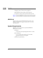
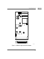
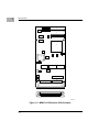
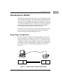
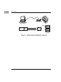
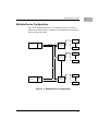
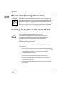
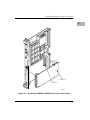
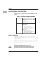
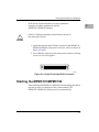
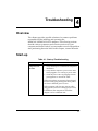
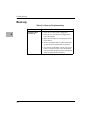
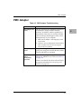
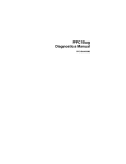
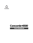
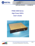
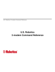
MPMC101 and MPMC102
PMC SCSI-2 Adapter
Installation and Use
PMC101A/IH2
Notice
While reasonable efforts have been made to assure the accuracy of this document,
Motorola, Inc. assumes no liability resulting from any omissions in this document,
or from the use of the information obtained therein. Motorola reserves the right to
revise this document and to make changes from time to time in the content hereof
without obligation of Motorola to notify any person of such revision or changes.
No part of this material may be reproduced or copied in any tangible medium, or
stored in a retrieval system, or transmitted in any form, or by any means, radio,
electronic, mechanical, photocopying, recording or facsimile, or otherwise,
without the prior written permission of Motorola, Inc.
It is possible that this publication may contain reference to, or information about
Motorola products (machines and programs), programming, or services that are
not announced in your country. Such references or information must not be
construed to mean that Motorola intends to announce such Motorola products,
programming, or services in your country.
Restricted Rights Legend
If the documentation contained herein is supplied, directly or indirectly, to the U.S.
Government, the following notice shall apply unless otherwise agreed to in
writing by Motorola, Inc.
Use, duplication, or disclosure by the Government is subject to restrictions as set
forth in subparagraph (c)(1)(ii) of the Rights in Technical Data and Computer
Software clause at DFARS 252.227-7013.
Motorola, Inc.
Computer Group
2900 South Diablo Way
Tempe, Arizona 85282
Preface
The information in this manual is adapted from the 4520/5520 PCI SCSI-2 Adapter
UserÕs Guide, Interphase part number UG05520-000. This manual replaces
PMC101A/IH1.
This manual describes the MPMC101 Single-Ended and MPMC102 Differential
SCSI-2 adapters, the installation of the adapters onto the carrier board, and the
installation of the AIX device driver.
The terminology and structure of this manual are directed to system
administrators, or those with equivalent technical experience.
The manual is organized as follows:
Chapter 1, Introduction, provides general information, product features, and
system requirements about the MPMC101 and MPMC102 SCSI-2 adapters, as well
as operating criteria and environmental limits for the adapters. A brief overview
of SCSI-2 architecture is also provided.
Chapter 2, Installation, provides instructions for installing the SCSI-2 adapters
onto the carrier board.
Chapter 3, AIX Driver Installation, provides instructions for installing the AIX
driver.
Chapter 4, Troubleshooting, provides tips and suggestions when having problems
with the installation or with the operation of the adapters.
Glossary is collection of common acronyms and terms used in describing SCSI
activity and functions.
Motorola¨ and the Motorola symbol are registered trademarks of Motorola, Inc.
Interphase¨ is a registered trademark of Interphase Corporation, Inc.
AIXª is a trademark of IBM.
All other products mentioned in this document are trademarks or registered
trademarks of their respective holders.
© Copyright Motorola, Inc. 1997
All Rights Reserved
Printed in the United States of America
April, 1997
Related Documentation
The publications listed below provide additional information pertinent to this
document.
Document Title
PCI Local Bus SpeciÞcation Rev 2.0; PCI Special Interest Group
Common Mezzanine Card SpeciÞcation; IEEE
PCI Mezzanine Card SpeciÞcation; IEEE
NCR 53C8XX ProgrammerÕs Reference Guide
Publication
Number
PCI Rev 2.0
P1386 Draft 1.5
P1386.1 Draft 1.5
J109311
Acronyms and Terminology
The following acronyms and terminology are often used in this manual instead of
the complete title or name:
AEN
CCB
CCS
CDB
CPU
DMA
ISA
LU
LUN
MIC
PCI
PMC
SCB
SCSI
Asynchronous Event Notification
Command Control Block
Command Control Set
Command Descriptor Block
Central Processing Unit
Direct Memory Access
Industry Standard Architecture
Logical Unit
Logical Unit Number
Media Interface Connector
Peripheral Component Interface
PCI Mezzanine Card
SCSI Control Block
Small Computer System Interface
For extended deÞnitions of the above and other common computer and SCSI
terms, please refer to the Glossary at the end of this UserÕs Guide.
Conventions
The following conventions are used in this document:
bold
is used for user input, as well as for the names of programs, directories,
files, commands, and options and arguments to commands.
italic
is used for names of variables to which you assign values. Italic is also used
for comments in screen displays and examples.
courier
is used for system output (e.g., screen displays, reports), examples, and
system prompts.
Enter
represents the Enter or Return key.
CTRL
represents the Control key. Execute control characters by pressing the
CTRL key and the letter simultaneously, e.g., CTRL-d.
Safety Summary
Safety Depends On You
The following general safety precautions must be observed during all phases of operation, service, and
repair of this equipment. Failure to comply with these precautions or with speciÞc warnings elsewhere in
this manual violates safety standards of design, manufacture, and intended use of the equipment.
Motorola, Inc. assumes no liability for the customer's failure to comply with these requirements.
The safety precautions listed below represent warnings of certain dangers of which Motorola is aware. You,
as the user of the product, should follow these warnings and all other safety precautions necessary for the
safe operation of the equipment in your operating environment.
Ground the Instrument.
To minimize shock hazard, the equipment chassis and enclosure must be connected to an electrical ground.
The equipment is supplied with a three-conductor ac power cable. The power cable must be plugged into
an approved three-contact electrical outlet. The power jack and mating plug of the power cable meet
International Electrotechnical Commission (IEC) safety standards.
Do Not Operate in an Explosive Atmosphere.
Do not operate the equipment in the presence of ßammable gases or fumes. Operation of any electrical
equipment in such an environment constitutes a deÞnite safety hazard.
Keep Away From Live Circuits.
Operating personnel must not remove equipment covers. Only Factory Authorized Service Personnel or
other qualiÞed maintenance personnel may remove equipment covers for internal subassembly or
component replacement or any internal adjustment. Do not replace components with power cable
connected. Under certain conditions, dangerous voltages may exist even with the power cable removed. To
avoid injuries, always disconnect power and discharge circuits before touching them.
Do Not Service or Adjust Alone.
Do not attempt internal service or adjustment unless another person capable of rendering Þrst aid and
resuscitation is present.
Use Caution When Exposing or Handling the CRT.
Breakage of the Cathode-Ray Tube (CRT) causes a high-velocity scattering of glass fragments (implosion).
To prevent CRT implosion, avoid rough handling or jarring of the equipment. Handling of the CRT should
be done only by qualiÞed maintenance personnel using approved safety mask and gloves.
Do Not Substitute Parts or Modify Equipment.
Because of the danger of introducing additional hazards, do not install substitute parts or perform any
unauthorized modiÞcation of the equipment. Contact your local Motorola representative for service and
repair to ensure that safety features are maintained.
Dangerous Procedure Warnings.
Warnings, such as the example below, precede potentially dangerous procedures throughout this manual.
Instructions contained in the warnings must be followed. You should also employ all other safety
precautions which you deem necessary for the operation of the equipment in your operating environment.
!
Warning
Dangerous voltages, capable of causing death, are
present in this equipment. Use extreme caution when
handling, testing, and adjusting.
All Motorola printed wiring boards are manufactured by UL-recognized
manufacturers, with a ßammability rating of 94V-0.
!
Warning
This equipment generates, uses, and can radiate electromagnetic energy. It may cause or be susceptible to
electro-magnetic interference (EMI) if not installed and
used in a cabinet with adequate EMI protection.
European Notice: Board products with the CE marking comply with the
EMC Directive (89/336/EEC). Compliance with this directive implies
conformity to the following European Norms:
EN55022 (CISPR 22) Radio Frequency Interference
EN50082-1 (IEC801-2, IEC801-3, IEEC801-4) Electromagnetic Immunity
The product also fulÞlls EN60950 (product safety) which is essentially the
requirement for the Low Voltage Directive (73/23/EEC).
This board product was tested in a representative system to show
compliance with the above mentioned requirements. A proper installation
in a CE-marked system will maintain the required EMC/safety
performance.
Contents
Overview ..................................................................................................................1-1
Product Features......................................................................................................1-1
AIX Driver................................................................................................................1-2
System Requirements .............................................................................................1-2
SpeciÞcations ...........................................................................................................1-5
Operating Environment ..................................................................................1-6
Introduction to SCSI-2 ............................................................................................1-7
Single-Target ConÞguration ...........................................................................1-7
Multiple-Device ConÞguration......................................................................1-9
Narrow and Wide SCSI ConÞgurations .....................................................1-10
Single-ended and Differential Connections ...............................................1-10
Cabling ............................................................................................................1-10
Termination.....................................................................................................1-10
Introduction .............................................................................................................2-1
Installation and ConÞguration Tasks ...................................................................2-1
Packaging .................................................................................................................2-1
Electro-static Discharge Precautions ....................................................................2-2
Installing the Adapter on the Carrier Board .......................................................2-2
Connecting to the SCSI Bus ...................................................................................2-6
Cabling Guidelines ..........................................................................................2-6
Starting the MPMC101/MPMC102 ......................................................................2-7
Installing the AIX Driver........................................................................................2-8
ConÞguring the SCSI Devices ...............................................................................2-8
Overview ..................................................................................................................3-1
Installing the AIX Driver........................................................................................3-1
Overview ..................................................................................................................4-1
Start-up .....................................................................................................................4-1
Boot-up .....................................................................................................................4-2
PMC Adapter ...........................................................................................................4-3
List of Figures
Figure 1-1. MPMC101 Single-ended SCSI-2 Adapter ........................................1-3
Figure 1-2. MPMC102 Differential SCSI-2 Adapter............................................1-4
Figure 1-3. Single Initiator, Single Target Systems .............................................1-7
Figure 1-4. Single Target with Multiple Peripherals ..........................................1-8
Figure 1-5. Multiple-Device ConÞguration .........................................................1-9
Figure 2-1. Installing the MPMC101/MPMC102 on the Carrier Board ..........2-5
Figure 2-2. 68-pin Front Panel SCSI Connector ..................................................2-7
List of Tables
Table 2-1. MPMC101/MPMC102 Adapter Jumper Settings .............................2-3
Table 2-2. Connector and Cable Requirements ...................................................2-6
Table 4-1. Start-up Troubleshooting......................................................................4-1
Table 4-2. Boot-up Troubleshooting......................................................................4-2
Table 4-3. PMC Adapter Troubleshooting ...........................................................4-3
xi
xii
1Introduction
1
Overview
The MPMC101 and MPMC102 provide fast and wide SCSI-2 (Small
Computer System Interface-2) high throughput connectivity for
host carrier boards equipped with PMC (PCI Mezzanine Card)
connections. The MPMC101 supports single-ended SCSI-2
connections; the MPMC102 supports differential SCSI-2
connections.
The adapters, combined with a 32-bit/33-Mhz PCI interface into
local CPU memory, provide a total wide and fast pathway for data.
This is especially important for servers, image processing,
high-speed networks, and other high performance peripherals. The
adapters are designed to operate within the framework of todayÕs
open systems architectures by providing physical and data-link
services as defined by the ANSI X3.131 specifications for SCSI-2.
The PMC adapters are plug-and-play devices with systems that are
compliant with the PCI Local Bus Specification (revision 2.0).
Product Features
The MPMC101 and MPMC102 SCSI-2 adapters have the following
capabilities:
❏
Single-wide PMC module
❏
32-bit, zero wait state PCI DMA master
❏
Up to 132 Mbps burst DMA rate
❏
20 Mbps Fast and Wide SCSI-2
❏
Single-ended (MPMC101) or differential (MPMC102) SCSI-2
interfaces
1-1
1
Introduction
❏
Support for up to 15 devices from a single slot
❏
64K EPROM for Network Boot or BIOS Firmware
❏
Compliance to PCI local bus specification (Revision 2.0)
Figure 1-1 shows the MPMC101 component layout and front panel.
Figure 1-2 shows the MPMC102 component layout and front panel.
AIX Driver
The device driver for the NCR53C825 SCSI Controller on the
MPMC101/MPMC102 is supplied with the AIX 4.1.4 or later
operating system.
System Requirements
Minimum system requirements to operate the MPMC101/
MPMC102 are as follows:
❏
Hardware:
Ð A Power PC system operating under AIX 4.1.4 or later
❏
Bus Architecture:
Ð An I/O interface that complies to PCI Local Bus
Specification Revision 2.0 or greater
❏
1-2
16MB total system memory
System Requirements
P2
JA3
C5
P1
U5
U4
U15
C4
U12
U14
JA4
U2
JA2
JA1
C3
F1
U6
U7
C6
U10
1964 9612
Figure 1-1. MPMC101 Single-ended SCSI-2 Adapter
1-3
1
1
Introduction
P2
+
C1
JA3
P1
U5
U4
U15
U12
U14
JA4
U2
JA2
U8
U11
U13
JA1
C3
RP3
F1
RP1
RP2
1963 9612
Figure 1-2. MPMC102 Differential SCSI-2 Adapter
1-4
Specifications
Specifications
The MPMC101/MPMC102 specifications are shown in the
following table.
Form Factor
Single-wide PCI Mezzanine Card (PMC)
Dimensions
2.9 inches wide (74 mm)
5.9 inches long (149 mm)
Host Bus Interface
PCI Local Bus Revision 2.0
SCSI Controller
NCR 53C825
SCSI Interface
Fast and Wide SCSI-2
SCSI Standard
ANSI X3.131-1994 SCSI-2
IEEE Compliance
IEEE P1386 Common Mezzanine Card and
IEEE P1386.1 PCI Mezzanine Card
SCSI ID
Software settable (factory default set @ 7)
SCSI-2 Data Handling
Synchronous:
Fast and Wide SCSI (20 megabytes/sec)
Fast SCSI (10 megabytes/sec)
Asynchronous:
Fast SCSI (10 megabytes/sec)
Host Data Transfer
32-bit bus master DMA transfers to 132
Mbps
Transfer Counter
24-bit
RAM
128 Kilobytes of static RAM
1 Kilobyte of NOVRAM
FIFO
64-byte DMA FIFO
Arbitration
16 bit arbitration (fair arbitration)
1-5
1
1
Introduction
Electrical Drivers
Single-ended or differential
Bus Connector
68-socket, Euro style SCSI
Operating Power
5 volts @ 1 A (maximum)
Reliability
190,509 hours mean time between failure;
107,681 hours at 95% conÞdence
Operating Environment
The MPMC101/MPMC102 requires the following operating
environment:
1-6
Operating temperature
0û to 55ûC
Storage temperature
-40û to 85ûC
Operating humidity, non-condensing
10 to 90%
Storage humidity, non-condensing
5 to 95%
Introduction to SCSI-2
Introduction to SCSI-2
SCSI (Small Computer System Interface) is an I/O bus protocol that
provides high performance, peer-to-peer data communications for
up to 16 devices, including one or more host computers. The main
advantage for using SCSI-2 is that all the initialization information
is stored within the SCSI-2 device. The hostÕs operating system can
obtain all the pertinent information about the device without
referencing external setup files or software drivers.
All SCSI devices are required to operate using asynchronous data
transfers. Synchronous transfers are optional, and negotiated
between the host and target during power-up.
Single-Target Configuration
In a SCSI-2 system, a computer with a host-adapter serves as the
primary initiator for all actions on the SCSI bus. All other devices
connected to the bus are SCSI targets. Figure 1-3 illustrates a simple
configuration where a host computer is connected to a single target,
a disk drive with an embedded SCSI controller. The controller can
be a stand-alone device with multiple peripherals as shown in
Figure 1-4.
Host Computer
Computer
Host
Adapter
Disk Drive
SCSI BUS
SCSI
Controller
Peripheral
11709 9701
Figure 1-3. Single Initiator, Single Target Systems
1-7
1
1
Introduction
SCSI Controller
Printers
Host Computer
Peripheral
Computer
Host
Adapter
Peripheral
SCSI BUS
SCSI
Controller
Peripheral
Peripheral
11710 9701
Figure 1-4. Single Target with Multiple Peripherals
1-8
Introduction to SCSI-2
Multiple-Device Configuration
The SCSI-2 architecture allows for multiple devices on the bus
where more than one host computer can communicate with more
than one target at a time.
Peripheral
Computer
Host
Adapter
SCSI BUS
SCSI
Controller
Peripheral
Peripheral
SCSI
Controller
Peripheral
Peripheral
Computer
Host
Adapter
SCSI BUS
SCSI
Controller
Peripheral
11711 9701
Figure 1-5. Multiple-Device Configuration
1-9
1
1
Introduction
Narrow and Wide SCSI Configurations
SCSI controllers can be daisy-chained together in a narrow
configuration using a 50-conductor, 8-bit cable to connect up to 8
SCSI devices on the bus. A wide configuration expands the bus to a
68-conductor, 16-bit bus that can handle up to 16 SCSI devices. Both
narrow (8-bit) and wide (16-bit) devices can be intermixed on a
wide SCSI bus (68-pin connector) only.
Single-ended and Differential Connections
There are two electrical alternatives, single-ended and differential.
A differential connection uses a set of two conductors to maintain a
positive (+) and a negative (-) polarity. Cable lengths up to 25
meters can be used for differential systems. A single-ended
connection uses a single conductor with a common ground to
transfer each signal. This conÞguration should only be used over
short distances up to 6 meters.
Single-ended and differential connections are electronically
incompatible, and can not be mixed on the same physical bus. The
overall performance of the two is about the same.
Cabling
Shielded and non-shielded cabling can be mixed on the same bus.
However, the non-shielded connections should be restricted to
internal cabinet applications only. All SCSI devices are configured
with a socket connector. The bus cable consists of the mating
pin-type connectors.
Termination
Both ends of the bus cable must be properly terminated. Interface
errors can be reduced if the termination voltage is maintained at the
extreme ends of the cable. All SCSI hardware include a setting
(usually with hardware jumpers) that allows the device to serve as
1-10
Introduction to SCSI-2
a terminator. Where possible, the SCSI devices serving as initiators
should supply terminator voltage. This is implemented with a
hardware jumper on the MPMC101/MPMC102.
1-11
1
2Installation
2
Introduction
This chapter contains instructions for installing the MPMC101 and
MPMC102 SCSI-2 adapters onto a carrier board.
Installation and Configuration Tasks
Perform the following tasks to install and configure the
MPMC101/MPMC102:
❏
Install the MPMC101/MPMC102 on the carrier board per the
instructions in Installing the Adapter on the Carrier Board on
page 2-2.
❏
Connect the SCSI cables per the instructions in Connecting to
the SCSI Bus on page 2-6.
❏
Power-up the system/Start the MPMC101/MPMC102 per
the instructions in the system chassis manual.
❏
Install the AIX SCSI-2 controller device driver per the
instruction in Chapter 3.
❏
Configure the SCSI devices per the guidelines in Configuring
the SCSI Devices on page 2-8.
❏
Reboot the system.
Packaging
The MPMC101/MPMC102 is packed in an anti-static package to
protect it from any static discharge. Observe standard handling
practices of static sensitive equipment.
2-1
Installation
2
Electro-static Discharge Precautions
Use ESD
Wrist Strap
Motorola strongly recommends that you use an antistatic wrist
strap and a conductive foam pad when installing the MPMC101 or
MPMC102. Electronic components can be extremely sensitive to
electro-static discharge (ESD). After removing the board from the
protective wrapper, place it component side up on a grounded,
static-free surface. Do not slide the board over any surface.
Installing the Adapter on the Carrier Board
!
Caution
Single-ended and differential SCSI devices are
electronically incompatible and cannot be mixed on the
same physical bus. Mixing single-ended and differential
SCSI devices on the same bus can cause permanent
damage to both the peripherals and the
MPMC101/MPMC102 adapter.
Follow these steps to install the MPMC101/MPMC102 on the
carrier board:
1. Place an ESD strap on your wrist and attach the grounding
line end of the ESD strap to the chassis as a ground. The ESD
strap must be secured to your wrist and to ground
throughout the procedure.
2. Remove the carrier board from the system chassis.
3. Lay the carrier board on a level surface with the PMC
connectors facing you.
4. Remove the PMC slot filler panel from the carrier boardÕs
front panel.
2-2
Installing the Adapter on the Carrier Board
5. Set the jumpers on the PMC adapter as described in Table 2-1.
Table 2-1. MPMC101/MPMC102 Adapter Jumper Settings
Jumper
Setting
JA1
When jumper is installed, the adapter supplies
terminator power to the SCSI bus.
Default = jumper installed
JA2
The SCSI bus terminators are enabled by this
jumper, as follows:
Default = MPMC101 jumper installed;
MPMC102 jumper not installed
JA3
No user capabilities.
Default = jumper not installed
JA4
When jumper is installed, the Big Endian mode
is enabled.
When no jumper is installed (default), Little
Endian mode.
Terminators - The SCSI bus (cable) must be properly
terminated at each end of the bus. The first and last device on
the bus should be the only devices that are set to terminate the
bus.
Terminator Power - The SCSI terminators require adequate
voltage to properly terminate the SCSI bus. All SCSI host
adapters on the bus should be set to supply terminator
power; and where possible, be located at the end of the bus
and serve as bus terminators.
The terminator resistors must be present on the first and last
device on the bus only.
6. (MPMC102) Remove the terminator resistor packs (RP1, RP2,
and RP3) if the PMC adapter is neither the first nor the last
device on the bus.
Use a small flat-headed screw driver to pry each resistor pack
from the adaptor. Be careful not to bend the connector pins on
the resistor packs or to damage the circuit board.
2-3
2
Installation
7. Remove the screws from the stand-offs on the component
side of the MPMC101/MPMC102.
2
8. Turn the MPMC101/MPMC102 component-side down, and
position it above the carrier board as shown in Figure 2-1 (an
MVME160x carrier board is shown).
!
Avoid touching areas of integrated circuitry; static
discharge can damage these circuits.
Caution
Note
Refer to Figure 2-1 when performing steps 9, 10, and 11.
9. Insert the 68-pin external SCSI-2 connector through the PMC
slot on the carrier boardÕs front panel.
10. Align the keying hole and P1 and P2 connectors on the
MPMC101/MPMC102 over the keying pin and the PMC
connectors on the carrier board.
11. Gently seat the MPMC101/MPMC102 onto the carrier board.
12. Turn the carrier board component-side down, and fasten the
four screws through the carrier board into the stand-offs on
the MPMC101/MPMC102.
13. Install the carrier board in the system chassis.
2-4
Installing the Adapter on the Carrier Board
2
P2
P1
KEYING HOLE
KEYING PIN
1965 9612
Figure 2-1. Installing the MPMC101/MPMC102 on the Carrier Board
2-5
Installation
2
Connecting to the SCSI Bus
You are now ready to connect the MPMC101/MPMC102 to the
SCSI bus.
Table 2-2. Connector and Cable Requirements
Connectors
68-pin Euro style SCSI:
Shielded - external or internal cabinet
applications
Non-shielded - internal cabinet
applications only
Bus Cable
68-conductor, flat ribbon or discrete:
Single-ended:
Type - twisted pair only
Shielding - match with connector
Max bus length - 6 meters
Differential:
Type - twisted pair only
Shielding - match with connector
Max bus length - 25 meters
Cabling Guidelines
Cable lengths up to 25 meters can be used for differential
configurations. Cable lengths up to 6 meters can be used for singleended configurations.
Shielded and non-shielded cabling can be mixed on the same bus;
however, the non-shielded connections should be restricted to
internal cabinet applications only.
!
Caution
2-6
Single-ended and differential SCSI devices are
electronically incompatible and cannot be mixed on the
same physical bus. Mixing single-ended and differential
Starting the MPMC101/MPMC102
SCSI devices on the same bus can cause permanent
damage to both the peripherals and the
MPMC101/MPMC102 adapter.
!
2
Cables of different impedance should not be mixed on
the same physical bus.
Caution
1. Attach the appropriate SCSI bus connector to the MPMC101/
MPMC102 adapter front panel connector, which is shown in
Figure 2-2 below.
2. Secure the bus connector to the front panel connector with lug
screws. Do not over tighten.
11668 9612
Figure 2-2. 68-pin Front Panel SCSI Connector
Starting the MPMC101/MPMC102
After installing the MPMC101/MPMC102 and attaching the cables,
turn the power on as directed in the system manual. The
MPMC101/MPMC102 should power-up automatically.
2-7
Installation
2
Installing the AIX Driver
The NCR53C825 SCSI-2 controller requires a wide SCSI controller
AIX driver. If the carrier board does not have an NCR53C825 SCSI2 controller on board, install and configure the AIX driver per the
instructions in Chapter 3.
You do not need to install the AIX driver if the carrier board has an
NCR53C825 SCSI-2 controller, or if the MPMC101/MPMC102 is
installed in the system when AIX is installed and configured. In
these situations, the wide SCSI controller driver is installed
automatically during Initial Program Load (IPL).
Configuring the SCSI Devices
Configure the devices with System Management Integration Tool
(SMIT). Use the following command to list the SCSI disk device
names:
lsdev -Cc disk | grep -i scsi
This indicates all SCSI disks found, not just the new ones. The new
devices are listed as Òdefined.Ó However, they are not ÒavailableÓ
until you configure the logical volumes and volume groups, and
create and mount the file systems.
Refer to the AIX System AdministratorÕs documentation for more
information on configuring the driver and peripheral devices.
2-8
3AIX Driver Installation
3
Overview
This chapter describes installation of the AIX SCSI-2 device driver.
Before installing the AIX device driver, install the MPMC101/
MPMC102 on the carrier board per the instructions in Chapter 2,
and install the carrier board into the system chassis.
Installing the AIX Driver
Follow these steps to install the SCSI-2 device driver using the AIX
System Management Integration Tool (SMIT):
1. Log into host system as root.
2. Insert the AIX Operating System CD-ROM into the CD-ROM
drive on the host system.
3. Type the following at the command prompt and press Enter.
smit devices
The Devices menu appears.
4. From the Devices menu, select Install Additional Device
Software.
A fill-in form appears, prompting you for the installation
input device.
5. Use List to select the installation CD-ROM drive that contains
the AIX software CD-ROM (example: /dev/cd0).
6. Press Enter.
A fill-in form appears, prompting you for the package you
want to install.
3-1
AIX Driver Installation
7. Answer the following questions as shown:
SOFTWARE to install
[devices.pci.00100300]
AUTOMATICALLY install requisite software?: [yes]
3
Leave the default values in the other fields.
8. Press Enter.
SMIT returns an ok command status message when the
process is complete.
9. After the driver installation is complete, return to the Devices
menu.
10. From the Devices menu, select Install/Configure Devices
Added After IPL.
A fill-in form appears, prompting you for the input device.
11. Answer the following question as shown:
INPUT device/directory for software
[none]
Leave the default values in the other fields.
12. Press Enter.
SMIT returns an ok command status message when the
process is complete.
13. Exit SMIT.
The SCSI-2 device driver is now installed.
3-2
4Troubleshooting
4
Overview
This chapter provides possible solutions for common problems
encountered while installing and operating the
MPMC101/MPMC102 SCSI-2 adapters. The following sections
describe various symptoms and corrective actions for your
computer and for the cards. If you are unable to resolve the problem
after performing the tasks listed in this chapter, contact Motorola.
Start-up
Table 4-1. Start-up Troubleshooting
Problem
Possible Solution
Computer will
not start
1. Verify that the power-on LED on the computer is
illuminated.
2. Verify that the computer’s power cord is intact
and is plugged in to a working ac power outlet.
3. Check the power source by plugging a known
good appliance or unit into the outlet.
If the system does not operate when plugged
into the outlet, plug the original unitÕs power
cord into a different power source.
If the computer still does not operate when
plugged into a known working power source,
troubleshoot the computer or install the
adapter card in a different unit.
4-1
Troubleshooting
Boot-up
Table 4-2. Boot-up Troubleshooting
4
4-2
Problem
Possible Solution
Computer does
not boot up
1. Check to see if the system is plugged in.
2. Check to see if your monitor is plugged into
your video adapter.
3. Make sure the adapter is seated properly on the
carrier board.
4. Remove the adapter and see if the system boots
up and returns to a normal state of operation.
5. Try a known, good adapter card in your system.
If the new board also fails, check the Read Me
item in the Main program group for information
about reconfiguring SCSI Adapters.
PMC Adapter
PMC Adapter
Table 4-3. PMC Adapter Troubleshooting
Problem
Possible Solution
Host adapter not
found
The PCI system in your computer is suppose to
automatically configure the bus address
locations. An address conflict is probably not
the problem. If the driver is correctly installed,
a driver message should appear on the screen
during boot-up of your computer.
1. Make sure the adapter is seated properly on the
carrier board.
2. Check for correct configurations of the SCSI bus
cable. A broken wire or inverted wiring can
cause SCSI reset problems.
SCSI drives not
found
Verify that the logical volumes and volume
groups are configured, and that the file systems
created with SMIT are mounted
SCSI drive errors
and/or
intermittent
operation
Check that the jumper setting on the
MPMC101/MPMC102 are correct (see Table 2-1
on page 2-3).
4
Check to see that the last drive on the SCSI bus
is properly terminated (see Connecting to the
SCSI Bus on page 2-6).
4-3
Glossary
ANSI (American National Standards Institute)
Organization which coordinates, develops and publishes standards
used in the United States.
asynchronous transmission
A data transmission technique where the initiator and the target lock
into a transfer of data, each block of data must be acknowledged before
the next block is transmitted.
Attenuation
Signal power lost in a transmission medium as the signal travels from
sender to receiver.
Bus Device Reset
A SCSI message to a target that instructs the target to clear all activity.
Byte
An eight-bit unit of data. It is usually the smallest addressable unit in
memory.
CBR (Constant Bit Rate)
The transmission of bits at a Þxed rate over a network or over a
communications bus.
CCB (Command Control Block)
A block of information prepared by the host computer, for the SCSI
adapter, to provide the adapter with parameters needed to execute a
SCSI command.
GL-1
Glossary
CCITT
International Telephone and Telegraph Consultative Committee.
The international standards body for telecommunications.
CCS (Command Control Set)
A standard set of SCSI commands used to communicate with SCSI
devices.
CDB (Command Descriptor Block)
A block of communication passed from the SCSI host to the SCSI
target that provides all control information the target needs to carry
out a command.
CPU (Central Processing Unit)
A personal computerÕs main microprocessor chip.
decode
The act of recovering the original information from an encoded
signal.
G
L
O
S
S
A
R
Y
differential
Refers to the electrical conÞguration of the signals used on the SCSI
bus. A set of two conductors are used to maintain a positive (+) and
a negative (-) polarity. This technique allows SCSI devices to
communicate over longer distances with minimum interference.
disconnect
The function used by a SCSI target to remove itself from the SCSI
bus and release the control of the bus to other users.
DMA (Direct Memory Access)
A fast method of moving data between two processor subsystems
without processor intervention.
GL-2
Glossary
driver
A software program, usually supplied by the device manufacturer, that
maps the interface of the device to the operating system of the host
computer.
EIA (Electronic Industries Association)
A standards organization specializing in the electrical and functional
characteristics of interface equipment.
EISA (Expanded Industry Standard Architecture)
A superset of the 8-bit/16-bit ISA bus architecture. By extending the
capabilities of the ISA standard, EISA provides full compatibility with
the ISA standard.
encode
The act of changing data into a series of electrical or optical pulses that
can travel efÞciently over a medium.
ES (End System)
A machine intended for running user application programs and
connected to a communications medium. In a SCSI bus system, it is the
SCSI device located at each end of the bus, preferably a host computer.
fast SCSI
A special set of timing commands for SCSI-2 that allows a faster
transfer of data than typical SCSI timers.
host
Generally, a computer or PC that contains a SCSI adapter used to
communicate with other devices on the SCSI bus.
host adapter
A device, usually in the form of a user interface card, that physically
connects a computer to the SCSI bus. It is generally referred to as an
adapter.
GL-3
G
L
O
S
S
A
R
Y
Glossary
host name
A unique number (0-15) that identiÞes each device on the SCSI bus.
Also referred to as the SCSI ID.
IEEE (Institute of Electrical and Electronic Engineers)
An information exchange organization. As part of its various functions,
it coordinates, develops, and publishes network standards for use in
the United States, following ANSI rules.
initiator
A device connected to a SCSI bus that requests an operation to be
performed by another SCSI device. Normally, it is the host computer
that initiates all actions on the bus. Targets can become an initiator
when they need to contact another device (other than the host) to
execute a set of commands. For example, the host could instruct a disk
drive to send a Þle to another disk drive. The Þrst disk drive
temporarily becomes an initiator while communicating and
transferring the Þle to the second disk drive.
interoperability
G
L
O
S
S
A
R
Y
The ability of all system elements to exchange information between
single vendor and multivendor equipment. Also called open
communications.
ISA (Industry Standard Architecture)
A well known architecture for the buses within personal computers
such as those used within the IBM PCs and compatibles.
ISO (International Standards Organization)
An international body that creates networking standards, including the
Open Systems Interconnections (OSI) model.
KB
Kilobytes. 1024 bytes.
GL-4
Glossary
local
Local refers to Þles and devices, such as disk drives, that are attached
to, or on your machine.
local bus
A bus on the motherboard of a personal or desktop computer that is
connected direct to the CPU, and brings the peripheral functions closer
to the microprocessor.
log in
The process of gaining access to a computerÕs operating system, often
by entering a user name and password.
LU (Logical Unit)
A physical device or virtual device that is addressed through a target.
For example, a bank of printers, connected to a SCSI controller (the
target), are Logical Units.
LUN (Logical Unit Number)
A 3-bit identiÞer for a Logical Unit (LU)
Mbps
Megabits (1,048,576 bits) per second.
narrow SCSI
A 50-conductor SCSI bus with 8-bit communications that can have up
to 8 SCSI devices attached.
open communications
The ability of all systems to exchange information between single
vendor and multivendor equipment. Also called interoperability.
GL-5
G
L
O
S
S
A
R
Y
Glossary
PCI (Peripheral Component Interconnect)
An Intel standard governing the connections and timings for a local bus
that is 32-bits wide operating at 33 MHz. It brings high speed
peripheral functions closer to the microprocessor while maintaining
compatibility with traditional 16-bit expansion systems operating at 8
MHz.
PMC (PCI Mezzanine Card)
An add-on printed circuit board that is mounted to a host carrier board,
with electrical connections to the carrier boardÕs PCI bus connectors.
point-to-point
Transmission of data between only two devices where one device is the
sender and the other device is the receiver.
propagation delay
The time it takes for a signal to travel across the SCSI bus.
protocol
G
L
O
S
S
A
R
Y
A set of rules and conventions that govern the exchange of information
between communicating devices.
RAM (Random Access Memory)
The type of computer memory where a byte of data can be read or
stored at any location.
reconnect
The arbitration used by a SCSI target to regain control of the bus to
continue communications with a SCSI host. The previous transmission
was most likely suspended with a time-out parameter to allow other
devices to use the bus.
GL-6
Glossary
SCSI (Small Computer System Interface)
An I/O bus protocol that provides high performance, peer-to-peer data
communications for up to 16 devices, including one or more host
computers.
SCSI device
Any peripheral that can be attached to a SCSI bus.
SCSI ID
A unique number (0-15) that identiÞes each device on the SCSI bus.
Also referred to as the host name.
single-ended
Refers to the electrical conÞguration of the signals used on the SCSI
bus. A single conductor with a common ground is used to transfer a
signal. This conÞguration should only be used over short distances up
to 6 meters. Longer distances require the use of a differential
conÞguration.
single-threaded
Only one program can be running on the computer at any given time.
synchronous transmission
A data transmission scheme in which Þxed time intervals are used to
transmit data across the SCSI bus. As opposed to asynchronous
transmissions, the acknowledgments are used for error checking only.
target
A SCSI device that performs operations in response to a request from
an initiator, usually the host computer.
wide SCSI
A 68-conductor SCSI-2 bus with 16-bit communications that can have
up to 16 SCSI devices attached. Narrow (50 conductor) and wide
devices can be intermixed on a wide SCSI bus only.
GL-7
G
L
O
S
S
A
R
Y
Glossary
word
A two-byte (16-bit) unit of data.
workstation
A networked computer typically reserved for end-user applications.
G
L
O
S
S
A
R
Y
GL-8
Index
A
acronyms 5
adapter
electrical interface 1-1
problems 4-3
AIX driver
installation 1-2, 2-8, 3-1
asynchronous
data rates 1-5
defined GL-1
asynchronous transmissions
usage 1-7
B
boot-up problems 4-2
C
cable
connectors 1-10
differential 2-6
impedance 2-7
lengths 1-10, 2-6
requirements 2-6
shielding 1-10, 2-6
single-ended 2-6
carrier board 2-2
cautions
cable impedance 2-7
connecting to SCSI Bus 2-6
connector
pin/socket 1-10
requirements 2-6
securing 2-7
shielding 2-6
controller, SCSI device 1-7
D
device driver 1-2, 2-8
installation 3-1
differential 1-10
cable 2-6
defined GL-2
drivers
defined GL-3
supported 1-2
E
electro-static discharge (ESD) 2-2
environment 1-6
ESD precautions 2-2
F
fast SCSI, defined GL-3
features 1-1
I
impedance, cable 2-7
initiator
defined GL-4
SCSI 1-7
installation
AIX driver 3-1
MPMC101/MPMC102 2-2
SCSI connectors 2-7
J
jumper settings
IN-9
Index
PMC Adapter 2-3
L
lengths, cable 1-10
M
memory requirements 1-2
multiple peripherals 1-7
multiple SCSI configurations 1-10
N
narrow configuration 1-10
narrow SCSI, defined GL-5
O
operating environment 1-6
P
PCI
defined GL-6
requirements 1-2
S
I
N
D
E
X
SCSI
configurations 1-7
connector port 2-7
connectors 2-6
controller 1-7
defined GL-7
fast, defined GL-3
host adapter 1-7
initiator 1-7
introduction 1-7
narrow 1-10, GL-5
target 1-7, GL-7
wide 1-10, GL-7
securing connectors 2-7
shielded cable 1-10
single SCSI configurations 1-7
single-ended 1-10
cable 2-6
defined GL-7
start-up problems 4-1
IN-10
synchronous
data rates 1-5
usage 1-7
synchronous transmissions
defined GL-7
system requirements 1-2
T
target
defined GL-7
SCSI 1-7
terminator power
PMC Adapter 2-3
terminator resistors
PMC Adapter 2-3
terminator voltage 1-10
terminators 1-10
PMC Adapter 2-3
troubleshooting 4-1
V
voltage
terminator 1-10
W
warnings
electrical compatibility 2-2, 2-6
wide configuration 1-10
wide SCSI, defined GL-7