1
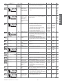
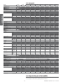
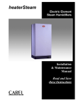
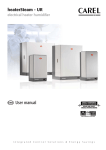
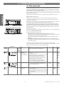
15. ALARMS AND TROUBLESHOOTING 15.1 Alarm summary table When an alarm is activated a message identifying the alarm is displayed on the control module. In the case of potentially dangerous alarms, the control module automatically shuts the humidifier down. For some alarm events (see Table 15.a), the signalling of the alarm is accompanied by the activation of an alarm relay, as described in: Other auxiliary contacts. If the cause of the alarm is no longer valid, the humidifier and alarm relay output can be reset automatically or manually, according to the type of problem, while the message displayed is deactivated manually by pressing the reset-PRG button. If no longer active, the alarm status continues to be indicated until the reset-PRG button is pressed. ENGLISH Still active alarms can not be reset. 30% 50% 75% 100% 1 2 3 4 alarm In the type C control module the presence of an alarm is indicated by the lighting up of LED 9 and a combination of the LEDs 5 (Fig. 15.a); in the event of more than one alarm, these are indicated in sequence, at 2 second intervals. In the type H or T control module, if not in programming phase, in the presence of an alarm LED 9 (see fig. 15.b) begins flashing, while the display 5 indicates the alphanumeric alarm code. The message is displayed cyclically, for a duration of two seconds, alternating with the measurement normally displayed (if the measurement normally displayed corresponds to a disconnected probe, the measurement is not displayed; this will automatically return to the display if the probe is reconnected). In the event of more than one alarm, the display indicates all the corresponding codes in sequence, at two second intervals. The alarm Ec cannot be reset. In the event of the alarm CL (regular maintenance required), the alarm can be reset only by resetting the hour counter; see Resetting the hour counter. reset 9 5 Fig. 15.a dehum. x1000 PRG reset SEL alarm 9 The alarm E1 may appear in two distinct cases: 1. Malfunction when reading from the parameter memory (typically on start-up) The default parameters are temporarily recalled, without being saved in the parameter memory (the parameters can be accessed and the correct values restored). In any case the default parameter recall procedure is recommended; see Recalling the default parameters. 2. Malfunction when writing to the parameter memory (typically on pressing the PRG button) Any modifications made will be cancelled; the parameters can be accessed, the values modified and save operation repeated. 5 Fig. 15.b Table 15.a lists the alarm indications, the causes, the conditions and the possible solutions. The remote terminal column indicates the alarm message that appears on the LCD display of the CAREL Humivisor remote control panel, if one is connected to the humidifier. code displayed H and T C controller controller alarm alarm non previsto 30% 50% 75% 100% 1 2 3 4 30% 50% 75% 100% 1 2 3 4 CAREL cause Humivisor remote terminal E202 •activation of safety thermostat • Klixon activation •the thp output is open E204 contradiction of the float E205 high conductivity of the supply water 58 solution (once having tried the suggestion, if the problem persists, contact the CAREL service department) action reset - check the earth current of the heaters, and if replace not available necessary. - manually reset the Klixon - problem dependent mainly on operation without water; - turn the machine off and, once it has cooled down,reactivate the thermostat on the cylinder cover after having cleaned the cylinder and the level control, checking the efficiency of the components; - check that the electrical and water connections are in order and that the machine is supplied correctly; - it may be necessary to replace the PTC sensors if installed - check the correct supply of water to the cylinder; see procedure manual - turn the machine off and clean: the cylinder, the level “AR” control and the fill electrovalve - turn the machine off and clean the water conductivity total shutdown measuring electrodes; - if the problem persists, change the source of the supply water or install a suitable treatment system (demineralisation, even partial); - the problem will not be resolved by softening the supply water auto available alarm relay active if Et remain in order at least a minute. only if EE appears during AR active heaterSteam +030222011 - rel. 2.2 - 24.01.2011 alarm alarm alarm 30% 50% 75% 100% 1 2 3 4 30% 50% 75% 100% 1 2 3 4 30% 50% 75% 100% 1 2 3 4 30% 50% 75% 100% 1 2 3 4 CAREL cause Humivisor remote terminal E211 autotest failed; probable problems in: supply water, level control or electrovalve solution (once having tried the suggestion, if the problem persists, contact the CAREL service department) action reset alarm relay - ensure that the machine is supplied with water; - turn the machine off and clean the level control and the fill valve see procedure “AR” manual E213 • electrical power not with the machine off and disconnected from mains power available; on machine supply, check that there are no defective of malfunctioning start-up no steam is electrical connections produced or the water is not pre-heated •float locked in high level position. see procedure “AR” manual E214 no water active only on the second EP or after EE during AR active only on the second EP or after EE during AR active E215 alarm not featured E231 not featured E221 not featured E222 not featured E224 E201 alarm 30% 50% 75% 100% 1 2 3 4 - check that the supply pipe from the water supply to the humidifier manual or humidifier and the internal pipe is not blocked or choked disabled automatic (if and that the pressure is sufficient (1-8 bar); after waiting - check the operation of the fill electrovalve; after waiting 10 10 min the - check that the steam supply does not have to work min the alarm water supply against excessive back-pressure, preventing the flow of is automatically returns) water into the cylinder due to gravity; reset and a - check that the steam supply pipe is not choked or that new fill cycle is there are no pockets of condensation attempted formation of foam in the - the formation of foam is usually due to the presence of signal only manual cylinder during boiling surfactants in the water (lubricants, solvents, detergents, water treatment or softening agents) or an excessive concentration of dissolved salts. Drain the water supply line; - clean the cylinder high water conductivity - check the conductivity of the supply water; humidifier auto pre-alarm - if necessary, install a suitable water treatment system; disabled available - the problem will not be resolved by softening the supply water high ambient humidity check the operation of the probe and the limit set by signal only auto (high temperature in T parameter P2 available control) low ambient humidity check the operation of the probe and the limit set by signal only auto low temperature in T parameter P3 available control) high outlet humidity check the operation of the outlet probe signal only auto available internal memory error contact the CAREL service department humidifier reprogram disabled CAREL not featured E212 user parameter error not featured E230 hour counter error not featured E220 room probe not connected not featured E223 not featured E225 not featured E232 E216 alarm 30% 50% 75% 100% 1 2 3 4 E233 alarm 30% 50% 75% 100% 1 2 3 4 with the machine off check that there are no defective or malfunctioning electrical connections reset the hour counter (see Resetting the hour counter) humidifier reprogram disabled parameters hour counter manual hour saving disabled counter reset humidifier auto disabled available check the connection of the probe and the setting of parameter A0 for ON/OFF configuration (see Reading and programming the parameters) outlet probe not concheck the connection of the probe or the setting of paramehumidifier nected (if featured) ter A0 (see Reading and programming the parameters) disabled NTC probe for measuring - check the pre-heating operation and the setting of pre heating parameters b1, b2, b3 (see Reading and programming the water temperature disabled not connected (if the parameters); featured) - check the connections to the terminal block on the cylinder cover regular maintenance stop the machine and carry out a complete maintenance signal only signal routine on the humidifier, resetting the hour counter (see Resetting the hour counter) no drain pre-alarm or - check the drain valve/pump; see procedure filter blocked - check if the pipes or the manifold are blocked; “AR” - check if the level sensor is faulty or the pipes are blocked; - the filter inside the boiler may be clogged. boiler full of water - check if the fill valve is leaking; signal only with no humidification - check if the high level sensor is dirty. demand pre-alarm not active not active active active active active active not active active auto available auto available active manual not active manual active on the second “Ed” not active auto available active Table 15.a heaterSteam +030222011 - rel. 2.2 - 24.01.2011 59 ENGLISH code displayed H and T C controller controller 15.2 Autotest Retry procedure (Fault tolerance) ENGLISH AUTOTEST RETRY (“AR”) Step Description 1 Stop production. Open contactor 2 3 4 Drain status Off Fill status Duration Condition that can stop “AR” Off Contactor status Off 3 sec No Drain by time On Off Off EE Off Off Off If at the end of a set time the float is below to the High level sensor active minimum reed, the procedure goes to step 3, otherwise it drains again and then goes to step 3 3 sec High level sensor active Wait for level to stabilise Fill water Off On Off Ends when the float reaches the control reed EE Display Contradiction of the levels EE High level sensor active The fill time exceeds a maximum limit 5 6 Wait for level to stabilise Off Drain On Off Off 10 sec Contradiction of the levels EE High level sensor Off Off Ends when the float reaches the control reed Contradiction of the levels EE High level sensor active The drain time exceeds a maximum limit 7 Wait for level to stabilise Off Off Off 1 sec Contradiction of the levels EE High level sensor active Tab. 15.b NOTE: - During the Autotest Retry procedure the display shows the code “AR” alternating with the alarm code that triggered the procedure. - If the PRG button is pressed during the Autotest Retry procedure, the procedure is stopped and normal humidifier operation resumes. 15.3 Troubleshooting Problem Cause Solution The control does not turn on 1. no electrical power supply; 1. check the protection devices upstream of the humidifier and the mains power supply; 2. close the switch: position I; 3. check that the connector are properly installed on the terminal block; 4. check the state of fuses F1/F2; 5. check that the secondary of the transformer has an output of 24 Vac. 1. close ON/OFF contacts (relay/terminals 7I - 8I); 2. check the external connection; The humidifier does not start 2. 3. 4. 5. 1. 2. 3. 4. 5. 6. The humidifier fills with water without producing steam external switch in position 0 (open); control connectors poorly installed; fuses blown; transformer malfunction. remote ON/OFF contact open (relay/terminals 7I - 8I); the external regulator/humidistat or probe has not been connected correctly; probe/humidistat malfunction; parameters not set correctly; safety thermostat activated; fan circuit breaker activated (H or T control); 1. steam outlet back-pressure too high; Line circuit breaker is activated 2. leaking flow regulator in the water fill electrovalve (with leaks in the water circuit); 3. level control malfunction; 4. cylinder inlet filter blocked; 5. lime in the fill tank; 6. drain electrovalve malfunction; 1. the line circuit breaker is rated too low; The humidifier wets the duct 2. resistors short-circuited 1. the distributor is not installed correctly; 3. 4. 5. 6. check the external signal; reprogram the parameters correctly; reset the thermostat after having eliminated the cause of the problem; reset the circuit breaker after having eliminated the cause of the problem; 1. check that the steam outlet pipe is not bent or choked; 2. replace the fill electrovalve; 3. 4. 5. 6. 1. 2. 2. the system is rated too high; 3. the humidifier is active when the duct fan is off; The humidifier wets the floor below 1. the humidifier pipe is blocked; 2. the water supply or overfill circuit has leaks; 3. the condensate drain pipe does not drain the water back to the fill tank; 4. the steam outlet pipe is not properly attached to the cylinder; 60 1. 2. 3. 1. 2. clean the level control or replace if necessary; clean the filter; clean the fill tank; check for the presence of 24Vac at the drain electrovalve; clean the drain electrovalve; check that the circuit breaker is rated for a current of at least 1.5 times the rated current of the humidifier; check, by measuring, the value of the resistors and replace them if necessary check that the steam distributor has been installed correctly; diminish the steam production set on the control; check the connection of the device (flow switch or differential pressure switch) linked to the humidifier for ventilation in the duct (terminals 7I - 8I) clean the pipe in the bottom tank; check the entire water circuit; 3. check the correct positioning of the condensate drain pipe in the fill tank; 4. check the fastening of the pipe clamp on the steam outlet pipe; Table 15.c heaterSteam +030222011 - rel. 2.2 - 24.01.2011 16. HUMIDIFIER TECHNICAL SPECIFICATIONS steam connection ( mm)( inch) supply pressure limits (Pa) supply water connection temperature limits (°C)(°fH) pressure limits (MPa) hardness limits (°fH) instant flow rate (l/min) (gpm) drain water connection ( mm)( inch) typical temperature (°C)(°fH) instant flow rate (l/min)(gpm) environmental conditions ambient operating temperature (°C) ambient operating humidity (% rH) storage temperature (°C) (°fH) storage humidity (% rH) index of protection control type voltage / auxiliary frequency (V / Hz) maximum auxiliary power (VA) probe inputs (general characteristics) power to active probes (general characteristics) alarm relay and dehumidification outputs (general characteristics) remote enabling input (general characteristics) serial communication heaterSteam +030222011 - rel. 2.2 - 24.01.2011 UR006 3 30/1.18 0…1500 0,6/0.13 0,6/0.13 1,2/0.26 model UR010 UR020 3 6 40/1.57 UR027 6 UR040 UR060 6 9 40/1.57 2000 G3/4”M 1T40/33.8T104 0.1 to 0.8 (1 to 8 bar) 40 1,2/0.26 4/0.88 4/0.88 2x40/1.57 4/0.88 10/2.2 40/1.57 100 / 212 5/1.32 22,5/5.94 1T40/33.8T104 10 to 60 -10T70/14T158 5 to 95 IP20 URC-URH-URS 24 / 50/60 30 selectable input signal: 0 to 1 Vdc, 0 to 10 Vdc, 2 to 10 Vdc, 0 to 20 mA, 4 to 20 mA input impedance: 60 k with signals: 0 to 1 Vdc, 0 to 10 Vdc, 2 to 10 Vdc 50 with signals: 0 to 20 mA, 4 to 20 mA 24 Vdc (24 Vac rectified), Imax= 250 mA 12 Vdc 5%, Imax= 50 mA 250 V 8 A (2 A) type of micro-switching action 1C free contact; max. resistance max. 50 ; Vmax=24 Vdc; Imax=5 mA two-lead RS485 Table 16.a 61 ENGLISH number of heating elements UR002 UR004 1 1 17. SPARE PARTS ENGLISH Exploded of the cylinder 6-10kg/h ( 13.2-22 lbs/h ) description PTC probe wire terminals NTC Probe Wire terminal bracket NTC well Power connection protection cover Cylinder cover 8 Cylinder gasket URKG100000 Cylinder cover locking clamp PTC probe Heating elements: with antiadherent film URKBR00000 11 7 9 10 12 13 - 208V 230V 400V 460V 575V without antiadherent film 208V 230V 400V 460V 575V Heating element centring spring 13C453A048 Cylinder Filter, ring nut and pipe union Gasket kit UR006 – 1 ~ * Spare Parts Code UR006 – 3~** UR010 – 3~** URKTB00000 URKNTC0000 URK0000022 URKNTCCAS1 URKCOPC00M n. 1 2 3 4 5 6 URKPTCS000 URKH00A347 URKH00A320 URKH00R347 URKH00R320 URKH00A347 URKH00A320 URKH00A320 URKH00A344 URKH00A341 URKH00R347 URKH00R320 URKH00R320 URKH00R344 URKH00P341 URKH00A346 URKH00A322 URKH00A322 URKH00A347 URKH00A342 URKH00R346 URKH00R322 URKH00R322 URKH00R347 URKH00R342 ---URKB100000 UEKF000000 URKG00000M Tab. 17.a Fig. 17.a 62 heaterSteam +030222011 - rel. 2.2 - 24.01.2011 Exploded of the cylinder 2-4 kg/h ( 4.4 - 8.8 lbs/h) 11 12 13 - description NTC probe NTC well PTC probe wire terminals Terminal fastening bracket Power connection protection cover Cylinder cover Cylinder gasket Cylinder cover locking clamp PTC probe Heating elements: with antiadherent film 208V 230V without antiadherent film 208V 230V cylinder filter, ring nut and pipe union Gasket kit Spare Parts Code UR002 UR004 URKNTC0000 URKNTCCAS2 URKTB00000 URK0000022 URKCOPC00S URKG100000 URKBR00000 URKPTCS000 URKH00A348 URKH00A348 URKH00R348 URKH00R348 ENGLISH n. 1 2 3 4 5 6 8 10 7 9 URKH00A349 URKH00A349 URKH00P349 URKH00P349 URKB040000 UEKF000000 URKG00000M Tab.le17.b Fig. 17.b heaterSteam +030222011 - rel. 2.2 - 24.01.2011 63 Exploded of the cylinder 20-27-40-60 kg/h 44.1-59.5-88.1-132.3 lbs/h ) description Heating element protection PTC probe 3 4 5 6 7 8 PTC probe wire terminals Cylinder cover Anti-foaming system Heating element assembly Cylinder gasket Heating element with antiadherent film 208V 230V 400V 460V 575V without antiadherent 208V film 230V 400V 460V 575V Heating element centring spring Cylinder NTC probe Use filter Use flange Pump fastening braket Drain pump Gasket kit ENGLISH n. 1 2 9 10 11 12 13 14 15 - UR020 Spare Parts Code UR027 UR040 ---URKPTCL000 UR060 URKTB00000 URKTB00000 URKTB00000 URKTB00000 URKCOP4000 URKCOP4000 URKCOP4000 URKCOP6000 URKFS00000 --- -- -- -- URKG400000 URKG400000 URKG400000 URKG600000 6x 6x 6x 9x URKH00A382 URKH00A381 URKH00A381 URKH00A386 URKH00A385 URKH00R382 URKH00R381 URKH00R381 URKH00R386 URKH00R385 URKH00A383 URKH00A382 URKH00A382 URKH00A381 URKH00A380 URKH00R383 URKH00R382 URKH00R382 URKH00R381 URKH00R380 URKH00A387 URKH00A390 URKH00A389 URKH00A387 URKH00A390 URKH00A389 URKH00R387 URKH00R390 URKH00R389 URKH00R387 URKH00R390 URKH00R389 URKB400000 URKNTC0000 URKB600000 ---URKB270000 URKF0000XL URKFLAN000 URKFLAN000 KITPSR0000 URKG0000XL URKG000XXL Table17.c Fig. 17.c 64 heaterSteam +030222011 - rel. 2.2 - 24.01.2011 17.a Maintenance of the other plumbing components IMPORTANT WARNINGS: do not use detergents or solvents to clean the plastic components. To remove the deposits use a 20% acetic acid solution, then rinse thoroughly with water. Water parts ur 2-10kg/h ( 4.4 - 22 lbs/h) Spare part codes UR002 to UR004 UR006 to UR010 UEKVASC000 URKT00000S URKT00000M KITVC00006 KITVC0012 URKSL00004 description tank Supply pipe Fill electrovalve Level control: sensor cap o-ring sensor floating sensor pipe control board Drain electrovalve A/D manifold (fill - drain) Drain pipe Overflow pipe URKDRAIN00 URKDRAIN00 URKT00000S URKT00000M ENGLISH n. 1 2 3 4 4a 4b 4c 4d 4e 5 6 7 8 Table 17.d Fig. 17.d Water parts ur 20-27-40-60 kg/h ( 44.1-59.5-88.1-132.3 lbs/h ) Spare part codes n. description UR020 UR027 UR040 1 2 3 4 4a 4b 4c 4d 4e 5 6 7 Overflow pipe Drain column Supply pipe Level control: Sensor cap o-ring sensor floating sensor pipe control board Drain pump Fill electrovalve Drain tank UR060 URKDC00000 URKT0000XL -- URKT0000XL URKT000XXL URKSL00004 KITPSR0000 KITVC00040 --- URKT000XXL KITVC00100 -Table 17.e • Fill electrovalve (Fig. 17.d, part. no. 3 - Fig. 17.e, part. no. 6) After having disconnected the cables and the pipe, remove the electrovalve and check the state of the inlet filter, cleaning it if necessary using water and a soft brush. Fig. 17.e • Supply and drain manifold (Fig. 17.d, part. no. 6) Check that there are no solid residues at the cylinder coupling; remove any impurities. Check that the O-ring is not damaged or cracked; replace it if necessary. • Drain electrovalve / drain pump (Fig. 17.d, part. no. 5 – Fig. 17.e, part. no.5) Disconnect the power cables, remove the bobbin and remove the valve block after having unscrewed the two fastening screws from the manifold; remove any impurities and rinse; as regards the pump it is sufficient to screw the clamping screw and remove possible impurities; • Fill tank (Fig. 17.d, part. no. 1) Check that there are no blockages or solid particles and that the conductivity measuring electrodes are clean, remove any impurities and rinse. • Supply, fill, overfill pipe (Fig. 17.a, part. no.2-8 – Fig. 17.e, part. no. 3-1) Check that they are free and do not contain any impurities; remove any impurities and rinse. • Level control (Fig. 17.d, part. no.4 – Fig. 17.e, part. no. 4) The level control must be released from the partition wall of the cabinet. Disconnect the connector from the terminals of the electronic board, take off the connection pipes. Release the spacers and the board, then take off the caps. Check that the o-rings are not damaged or cracked; replace them if necessary. Check the cleanliness and free sliding of the two float switches. Clean all the components and reassemble and replace the device. heaterSteam +030222011 - rel. 2.2 - 24.01.2011 65 Carefully check that the connection pipes are properly fitted and that they are not blocked or choked at any point. IMPORTANT WARNING: after having replaced or checked the plumbing components, check that the connections have been carried out correctly, with their corresponding seals. Re-start the machine and run through a number of fill and drain cycles (from 2 to 4), at the end of which, applying the safety procedure, check for any water leaks. 17.2 Replacing the components 17.2.1 Non-stick film ENGLISH If requested as an option, the internal wall of the cylinder is lined with a non-stick film to avoid lime being deposited on the internal walls of the cylinder. To clean or replace the film, remove the cylinder following the procedure described in Maintenance of the cylinder-cylinder and then: • slowly remove the film towards the mouth of the cylinder, without forcing it to avoid damage; • open the film after having released the click-on couplings; • clean the film with water and a plastic spatula if necessary; replace the film if damaged; • wind the film around itself, reinserting the click-on couplings, and place it into the cylinder after the latter has been carefully cleaned and freed from deposits. 17.2.2 Elements To replace the elements remove the cylinder following the procedure described in Maintenance of the cylinder-cylinder and loosen the fastening nuts from the threaded spigots of the elements. Before reassembling the elements, check the state of the gaskets and replace them if necessary. 17.2.3 PTC overtemperature sensor The PTC sensors (one for each heating element) do not require regular maintenance; they should only be replaced if the safety thermostat is activated due to operation without water: in fact, the intervention of just one PTC will cause the control module to shut-down operation. To replace the sensors, remove the cylinder following the procedure described in Maintenance of the cylinder-cylinder and then: • disconnect the PTC sensor terminals (see Fig.: 7.p.a to 7.p.n); • remove the electrical elements corresponding to the sensors being replaced; • unscrew the PTC sensor (fig. 17.a, part. no. 7 or Fig. 17.b part. no. 7 or Fig. 17.c part. no. 2) using a spanner on the hexagonal spigot, accessible from the under side of the cover; • reassemble a new PTC sensor, replacing the o-ring and screwing it tight; reconnect the terminals; • reposition the electric heating elements, making sure the PTC sensor enters into the corresponding sheath in the aluminium casting. 17.2.4 NTC temperature sensor (version with type H or T control module only) As for the PTC sensors, the NTC sensor controlling the water temperature does not require regular maintenance. To replace this sensor, remove the cylinder following the procedure described in Maintenance of the cylinder-cylinder and then: • disconnect the terminals of the NTC sensor (see Fig.: 7.p.a to 7.p.n); • remove the sensor from the well housed in the measuring sheath (fig. 17.a part. no. 2, or Fig. 17.b part. no. 1, or Fig. 17.d part. no. 11); • reposition and connect the new sensor in the place of the old one. 66 heaterSteam +030222011 - rel. 2.2 - 24.01.2011 17.2.5 Fuses (uxiliary circuit) These measure 10.3 x 38mm and are housed in the fuse cartridge; to check the state of the fuses, check their continuity using a tester. Use the types of fuses indicated in table 17.e. UR002 fuses 1 and 2 transformer power supply fuses 3 pump protection (on humidifiers from 20 to 60kg/h) (44.1 to 132.3 lbs/h) Fuse 4 transformer secondary models UR004 UR006 - 1~* UR006 -3~** UR010 UR020 UR027 UR040 UR060 All fast blow and capacity 1 A, GL, 10,3x38 contained in fuse carrier on Omega rail 1 A GL , 10,3x38 FAST 2,5 A,T 5x20 in pottery Table 17.f ENGLISH *: single-phase **: three-phase 17.2.6 Load protection fuses (humidifiers UR027 at 208-230 V, UR060 at 460 V) Dimension of the fuses 27x60 mm rapid, housed in fuse carrier bases that can be selected. Check their continuity using a tester. fuses F5, F6, F7 fuses F8, F9, F10 UR027 40 A, GG 40 A, GG UR060 35 A, GG 50 A, GG Table 17.g 17.2.7 Solid state relays (version with type H or T control module only) The solid-state relays (one in the single-phase unit, two in the three-phase unit) can malfunction in one of two ways: by short-circuit or burn-out. The respective consequences for the supply of power are: continuous conduction or permanent opening. In the event of malfunctioning, check the conduction of the relay using a tester. For the replacement of the solid-state relay: • turn the humidifier off; • open the disconnection switch in the power line (safety procedure); • disconnect the power and auxiliary cables from the solid-state relay terminal block; • remove the relay from the electrical panel by using a screwdriver to lower the fastening lever to the omega guide; • replace the new relay on the omega guide and reconnect the wires as before. 17.2.8 Cooling fan and circuit breaker (version with type H or T control module only) The SSR relays are cooled by a fan placed in the upper part, on the right side of the machine for the 20-60kg/h (44-132.2lbr/h) models, or placed on the base of the humidifier for the models up to 10kg/h (22lbr/h). With insufficient ventilation the temperature of the electrical panel may rise excessively until, reaching 65°C, power to the solid-state relays is cut by a special Klixon (heat sensor, used in this application as circuit breaker - hereafter: circuit breaker), with manual reset (indicated by S2 in the wiring diagram) and without an activation signal. In this case, check: • Whether the thermoprotective placed in the din rail near to the SSR relays has been working, or placed in front of the baffle pressing the reset button (see Fig. 17.f); • that the fan power board, fitted in front of the baffle, is powered (input terminals: 24 Vac) and in turn powers the fan (output terminals: 24 Vdc), (only for models up to). 3 1 1 If the fan is faulty: - in the models up to 10 Kg/h (22 lbs/h): • remove the baffle, after having unscrewed the two side nuts for fastening to the partition of the appliance; In case of malfunction, the thermoprotective can be replaced unscrewing the fastening screws; - in the 20-27-40-60 Kg/h ( 44.1-59.5-88.1-132.3 lbs/h ) models: • unscrew the 4 fastening screws placed on the right side of the structural work and extract the fan from the inside of the panel. In case of malfunction, the thermoprotective can be replaced removing the polycarbonate transparent protection of the solid state relays and unscrewing the fastening screws. Key: 1 2 3 4 2 2 4 Klixon (thermoprotective - where fitted) solid state relay (SSR) (where fitted) fan (where fitted) heatsink 3 Fig. 17.f heaterSteam +030222011 - rel. 2.2 - 24.01.2011 67 17.3 Spare parts Models ENGLISH plumbing humidifier gasket kit Cylinder gasket kit cylinder cover kit boiler cover locking bracket cylinder filter kit Teflon-coated heating elements 208 V 230 V 400 V 460 V 575 V non-Teflon heating elements 208 V 230 V 400 V 460 V 575 V cylinder fastening strap steel cylinder fill tank drain electrovalve kit drain pump kit drain pipe kit fill valve internal pipe kit level control with sensor non-stick film external terminal covering electrical parts contactor voltage 208 V 230 V 400 V 460 V 575 V Auxiliary contact power supply transformer voltage 230 - 400 V 208 - 208 460 - 575 V fuse carrier voltage 460 V 208-230 V fuses F1, F2 208-230 V 400V 460-575 V F3 400V 208-230460-575 V F4 F5, F6, F7, F8, F9, F10 from 40 A UR002 UR004 URKG00000M URKG100000 URKCOPC00S URKBR00000 UEKF000000 URKG00000M URKG100000 URKCOPC00S URKBR00000 UEKF000000 URKG00000M URKG100000 URKCOPC00M URKBR00000 UEKF000000 URKH00A348 URKH00A348 URKH00A349 URKH00A349 URKH00A347 URKH00A320 URKH00R348 URKH00R348 UR006 - 1~* UR006 - 3~** URKH00R349 URKH00R349 URKH00R347 URKH00R320 UR010 UR020 UR027 UR040 UR060 URKG00000M URKG100000 URKCOPC00M URKBR00000 UEKF000000 URKG00000M URKG100000 URKCOPC00M URKBR00000 UEKF000000 URKG0000XL URKG400000 URKCOP4000 URKG0000XL URKG400000 URKCOP4000 URKG0000XL URKG400000 URKCOP4000 URKG000XXL URKG600000 URKCOP6000 URKF0000XL URKFLAN000 URKF0000XL URKFLAN000 URKF0000XL URKFLAN000 URKF0000XL URKFLAN000 URKH00A347 URKH00A320 URKH00A320 URKH00A344 URKH00A341 URKH00A346 URKH00A322 URKH00A322 URKH00A347 URKH00A342 URKH00A382 URKH00A381 URKH00A381 URKH00A386 URKH00A385 URKH00A383 URKH00A382 URKH00A382 URKH00A381 URKH00A380 URKH00A387 URKH00A390 URKH00A389 URKH00A387 URKH00A390 URKH00A389 URKH00R346 URKH00R322 URKH00R322 URKH00P347 URKH00R342 URKBLOCK00 URKB100000 UEKVASC000 URKDRAIN00 URKH00R383 URKH00R382 URKH00R382 URKH00R381 URKH00R380 -URKB270000 --KITPSR0000 URKT0000XL KITVC00040 URKT0000XL URKSL00004 -URKTI27000 URKH00R387 URKH00R390 URKH00R389 -URKB400000 --KITPSR0000 URKT000XXL KITVC00040 URKT000XXL URKSL00004 -URKTI40000 URKH00R387 URKH00R390 URKH00R389 -URKB600000 --KITPSR0000 URKT000XXL KITVC00100 URKT000XXL URKSL00004 -URKTI60000 URKCONT200 URKCONT400 URKCONT200 URKCONT500 URKCONT300 URKCONT300 URKCONT300 URKCONT500 URKBLOCK00 URKB040000 UEKVASC000 URKDRAIN00 URKBLOCK00 URKB040000 UEKVASC000 URKDRAIN00 URKBLOCK00 URKB100000 UEKVASC000 URKDRAIN00 URKH00R347 URKH00R320 URKH00R320 URKH00R344 URKH00R341 URKBLOCK00 URKB100000 UEKVASC000 URKDRAIN00 KITVC00006 URKT00000S URKSL00004 URKBAG0400 URKTI04000 KITVC00006 URKT00000S URKSL00004 URKBAG0400 URKTI04000 KITVC00012 URKT00000M URKSL00004 URKBAG1000 URKTI10000 KITVC00012 URKT00000M URKSL00004 URKBAG1000 URKTI10000 KITVC00012 URKT00000M URKSL00004 URKBAG1000 URKTI10000 URKH00R382 URKH00R381 URKH00R381 URKH00R386 URKH00R385 --URKB270000 ---KITPSR0000 URKT0000XL KITVC00040 URKT0000XL URKSL00004 --URKTI27000 URKCONT100 URKCONT100 URKCONT100 URKCONT100 URKCONT100 URKCONT400 URKCONT100 URKCONT100 URKCONT100 URKCONT100 URKCONT100 URKCONT100 URKCONT200 URKCONT200 URKCONT200 URKCONT500 URKCONT400 URKCONT300 URKCONT200 URKCONT200 URKCONT200 URKCONT500 URKTR10000 URKTR20000 URKTR10000 URKTR20000 URKTR10000 URKTR20000 URKTR10000 URKTR20000 URKTR10000 URKTR20000 URKTR40000 URKTR30000 URKTR40000 URKTR30000 URKTR40000 URKTR30000 URKTR40000 URKTR30000 URKFH10000 URKFH10000 URKFH10000 URKFH10000 URKFH10000 URKFH20000 URKFH20000 URKFH20000 URKFH20000 URKFH30000 URKFUSE300 URKFUSE100 URKFUSE300 URKFUSE400 URKFUSE300 URKFUSE100 URKFUSE300 URKFUSE400 URKFH30000 URKFUSE100 URKFUSE100 URKFUSE100 URKFUSE100 URKFUSE300 URKFUSE100 URKFUSE100 URKFUSE300 URKFUSE100 URKFUSE200 URKFUSE300 URKFUSE100 URKFUSE300 URKFUSE400 URKFUSE200 URKFUSE300 URKFUSE100 URKFUSE300 URKFUSE400 URKFUSE500 URKFUSE500 URKFUSE500 URKFUSE700 URKFUSE500 (208-230V) F5, F6, F7 F8, F9, F10 from 35 A (460V ) from 50 A (460V) URKFUSE600 URKFUSE800 fan Motor protector URKFANS000 THP00A0000 URKFANS000 THP00A0000 URKFANS000 THP00A0000 URKFANS000 THP00A0000 URKFANS000 THP00A0000 socket for pre-heater probe electronic parts version C control module version H control module version T control module main control board flat connection cable fan and SSR motorprotector boiler motorprotector fan circuit breaker fan control board solid state relay URKNTCCAS2 URKNTCCAS2 URKNTCCAS1 URKNTCCAS1 URKNTCCAS1 URI0000000 59C460A003 URKKL10000 URI000000i 59C460A003 URKKL10000 6132702AXX URKCFAN000 6132702AXX URKCFAN000 URCxxvppri (for further information see the CAREL instruction sheet code +050003700) URHxxvppri (for further information see the CAREL instruction sheet code +050003700) URSxxvppri (for further information see the CAREL instruction sheet code +050003700) URI000000i URI000000i URI000000i URI000000i URI000000i 59C460A003 59C460A003 59C460A003 59C486A003 59C486A003 URKKL10000 URKKL10000 URKKL10000 URKKL10000 URKKL10000 URKKL00000 URKKL00000 6132702AXX 6132702AXX 6132702AXX 6132702AXX 6132702AXX URKCFAN000 URKCFAN000 URKCFAN000 URKSSR1000 208 V URKSSR1000 230 V URKSSR1000 400 V URKSSR1000 460 V 575 V PTC probe (res. without antiadherent film) URKPTCS000 URKNTC0000 NTC probe (res. with antiadherent film) URKSSR1000 URKSSR1000 URKSSR1000 URKSSR1000 URKSSR2000 URKSSR2000 URKPTCS000 URKNTC0000 URKPTCS000 URKNTC0000 URKSSR1000 URKSSR1000 URKSSR1000 URKSSR1000 URKSSR1000 URKPTCS000 URKNTC0000 URKSSR2000 URKSSR1000 URKSSR1000 URKSSR1000 URKSSR1000 URKPTCS000 URKNTC0000 URKFANL000 THP00A0000 URKKL00000 URKSSR3000 URKSSR3000 URKSSR3000 URKSSR3000 URKSSR3000 URKPTCL000 URKNTC0000 URKFANL000 THP00A0000 URKKL00000 URKSSR3000 URKSSR3000 URKSSR3000 URKSSR3000 URKSSR3000 URKPTCL000 URKNTC0000 URKFANL000 THP00A0000 URKKL00000 URKFANL000 THP00A0000 URKKL00000 URI000000i 59C486A003 URKKL10000 URKKL00000 6132702AXX URI000000i 59C486A003 URKKL10000 URKKL00000 6132702AXX URKSSR3000 URKSSR3000 URKSSR3000 URKPTCL000 URKNTC0000 URKSSR3000 URKSSR3000 URKSSR3000 URKPTCL000 URKNTC0000 Table 17.h *: single-phase **: three-phase 17.4 Disposal of the parts of the humidifier The humidifier is made up of metallic and plastic parts, refer to Figs. 2.a e 14.b. All these parts must be disposed of according to the local standards regarding product waste disposal. 68 heaterSteam +030222011 - rel. 2.2 - 24.01.2011