1
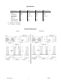
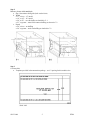
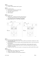
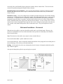
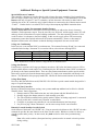
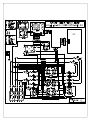
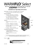
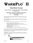
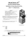
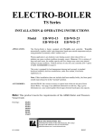
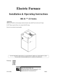
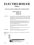
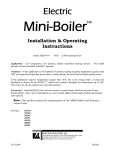
THE NEXT GENERATION OF THE INDUSTRY STANDARD PLENUM HEATER Installation & Operating Instructions EM-WU(WD)***S*-SL1 Series – One Stage HP or One or Two Stage AC See specification page for model number breakdown and details Dual Heat Combinations Heat pump – WarmFlo Select – gas/oil furnace, 1 or 2 burner stage, single speed or ECM blower AC – WarmFlo Select – gas/oil furnace, 1 or 2 burner stage, single speed or ECM blower AC, 2 stage – WarmFlo Select – gas/oil furnace, 1 or 2 burner stage, single speed or ECM blower Application New construction, new HP or AC and new furnace Conversion – existing HP or AC and furnace Conversion – HP replacing AC, same furnace Conversion – upgrade furnace and add WarmFlo Select plenum heater Conversion – without AC or HP, okay Conversion – no furnace, add to HP/air handler Conventional H/C Roomstat Only Configure programmable thermostat for conventional, 1H/1C for one stage compressor or 2H/2C for 2 stage AC This unit will not work with a heat pump roomstat Attention – Power Company Load Control Technician or Representative One set of wires takes care of both summer and winter load control. DO NOT DESTROY THIS MANUAL. PLEASE READ CAREFULLY AND KEEP IN A SAFE PLACE FOR FUTURE REFERENCE BY A SERVICE TECHNICIAN. Drawings: 05/15/2009 EH709, EH712, UAW358, UAW359, UAW360, UAW361, XX017 EI709 Table of Contents Specification 1 Product Dimensions 1 Introduction 2 Installation Requirements 3 Mechanical Installation Upflow 4 Downflow 7 Horizontal 8 Electrical Hookup 9 Additional Hookup or Special System Equipment Concerns 12 Field Setup or Programming 14 Operation Indicators 19 Troubleshooting 20 Manual Reset 22 System Airflow 22 Installation Checkout 23 Drawings Included: 05/15/2009 EH709 EH712 UAW358 UAW359 UAW360 UAW361 XX017 EI709 Specification Model Number EM-W*102S+ EM-W*153S+ EM-W*204S+ EM-W*254S8 kW rating BTUH Voltage/Phase Circuit Breaker Source Feed Elements Max. Temp. Rise Shipping Weight 10 34000 240/1 60 1 4 55° F 24# 15 51000 240/1 1-30, 1-60 2 6 55° F 30# 20 68000 240/1 2-60 2 8 55° F 32# 25 85000 240/1 1-30, 2-60 3 10 55° F 34# * U = Upflow, D = Downflow + 5 = 15” wide, 8 = 18” wide Product Dimensions Upflow 05/15/2009 Downflow 1 EI709 Introduction The intended application for this product is summarized on the cover page. If this does not fit your application needs or HVAC system design, do not modify or attempt to use this model other than its designed and intended usage. Electro Industries manufactures other products which may fit your requirement, example: Electro-EZ-Mate – 10 kW only, 5 kW load shed Basic plenum heater, without WarmFlo – EM-LV or EM-LD Series Plenum heater, HeatChoice – EM-EU or EH-***-* Basic duct heater – EM-WE or EM-DI Series Electric furnace – HE-*-**-** When installed according to this installation manual and inspected by your local power company representative, your dual heating system may qualify for special off-peak electric or dual fuel kWh rates. Easy and direct connection for the utility load control receiver, both winter and summer control. This repackaged model series includes the basic, patented, WarmFlo Select mechanical design – type of element, element position, directed airflow, enclosure cooling plate, approved zero clearance A-coil or furnace, etc. In addition, this WarmFlo Select has a special controller which allows for simplified control wiring, easy heat pump or furnace interface. Smart controller, fully automatic o Outdoor and warm air temperature sensing o Electric element modulation, increased comfort and uniform heating o Electric element modulation, minimum resistant element usage o One room thermostat, entire system o Controls and reacts with heat pump, tempers output for comfort and total season heating o Controls and interacts with any gas/oil furnace, single or staging burner o Applicable to single and ECM variable speed furnace blowers o Installer setup switch, selects heat pump or non-HP, etc. Dual heat – since this is in addition to a gas or oil forced air furnace and ducting system, the furnace system must be installed complete and in good working (gas in tank) condition prior to energizing or using this WarmFlo Select – furnace itself, heat pump (or AC), gas supply, permanent wired room thermostat, WarmFlo sensors, completed ducting system with proper filter, etc. There are certain interacting functions within the WarmFlo Select controller, if the total system does not respond correctly it may lock up and there could be a loss of heating. Heat pump only – if there is no gas or oil furnace, setting the mode switch to “no gas” will prevent potential lock-up. NOTE: This installation and operating manual is the property of the equipment purchaser and should remain with the installed unit. If the installing contractor desires other copies, access Electro Industries’ documentation channel. For information, this unit is rated at 240VAC, single phase. When operating at lower source voltage, the output is reduced, example 208VAC, a 20 kW unit is effectively only 15 kW. Warning: To properly maintain the 20-year specified warranty conditions of this WarmFlo Select unit, correct installation within the furnace plenum is required. This installation manual provides the necessary details, the installing contractor has the responsibility to install as detailed and test this unit to verify proper airflow, non-hi-limiting conditions, etc. 05/15/2009 2 EI709 Installation Requirements 1. All installation work must be performed by trained, qualified contractors or technicians. Electro Industries, Inc., sponsors installation and service schools to assist the installer. Visit our web site at electromn.com for upcoming service schools. WARNING ALL ELECTRICAL WIRING MUST BE IN ACCORDANCE WITH NATIONAL ELECTRIC CODE AND LOCAL ELECTRIC CODES, ORDINANCES, AND REGULATIONS. WARNING OBSERVE ELECTRIC POLARITY AND WIRING COLORS. FAILURE TO OBSERVE COULD CAUSE ELECTRIC SHOCK AND/OR DAMAGE TO THE EQUIPMENT. CAUTION This unit can only be used for its intended design as described in this manual. Any internal wiring changes, modifications to the circuit board, modifications or bypass of any controls, or installation practices not according to the details of this manual will void the product warranty, the ARL certification label, and manufacturer product liability. Electro Industries, Inc., cannot be held responsible for field modifications, incorrect installations, and conditions which may bypass or compromise the built-in safety features and controls. 2. This installation manual and WarmFlo Select products relate only to the addition of the WarmFlo Select plenum heater to the furnace ducting system external to the gas or oil force air furnace. The owner/ installer assumes all responsibility and/or liability associated with any needed installation of the gas/oil furnace, fuel system, flue, chimney, etc. Any instructions or comments made within this manual (or factory phone assistance) relating to the gas/oil furnace are provided as comments of assistance and “helps” only. CAUTION This unit shall not be operated (either heating section or blower) until the interior of the structure is completed and cleaned. This also means all duct work must be complete with filter, etc. Both manufacturers’ warranties are void if this unit is operated during structure construction. CAUTION Hazards or unsafe practices could result in property damage, product damage, severe personal injury and/or death. Remember, safety is the installer’s responsibility and the installer must know this product well enough to instruct the end user on its safe use. Safety is a matter of common sense - - a matter of thinking before acting. Professional installers have training and experienced practices for handling electrical, sheet metal, and material handling processes. Use them. 05/15/2009 3 EI709 Mechanical Installation – Upflow For downflow or horizontal see appropriate section. This upflow section provides more illustrations and details. The installer should review this section and then relate the comments under downflow or horizontal as they apply. This section assumes there is either an A/C or HP A-coil, if there is no coil in the plenum simply proceed without visualizing the presence of the A-coil. Typically this means the WarmFlo Select unit will be directly above the furnace cabinet. However, if there is vertical space in the plenum (especially oil furnace), insert the WarmFlo Select approximately 2/3 up. N or W coils – for close coupling to the refrigerant coil, only A-coil is approved. If using an N or Wcoil, must allow at least 12” space between the refrigerant coil and the bottom of this WarmFlo Select unit. The WarmFlo Select is designed with a special double plate at the element mounting. Cool air from the blower must enter between these two plates. Therefore, the WarmFlo Select must be inserted into the plenum such that the mounting plate is even with the edge of the furnace hot air outlet hole. Do not necessarily line up the WarmFlo Select control box with the furnace cabinet front. The concern is the cutout in the plenum mating with WarmFlo Select element plate. Using this sketch and visualizing the WarmFlo Select installation, work through the following eight steps: Step 1 Observe and select insert location, furnace plenum a. Above A-coil b. Hole cutout must be at A-coil end 2 sides of plenum choice, not 4 c. Hole cut plenum end, 8” free space above A-coil top d. 10” minimum, between control box and plenum top e. All distribution ducts above A-coil top 05/15/2009 4 EI709 Step 2 Measure plenum width and depth a. Step 1 determines facing side (hole cut decision) b. Width 17” or less – 15” model 18” or 19” – 18” model 20” to 22” – use side baffles as detailed in C-1 23” or greater – must field construct baffling as shown in C-2 c. Depth 20” or less – no baffling 20” or greater – need rear baffling as detailed in C-2 Step 3 Cut insert hole a. Template provided in documentation package – use 8” opening for this model series 05/15/2009 5 EI709 Step 4 Add necessary baffling a. See Step 2 for determination and if required Step 5 Insert unit and bolt in place a. Extend center V deflector to plenum depth b. Do not drill into refrigerant lines c. Note airflow decal d. Seal as required Step 6 Install WarmFlo sensors a. Outdoor (OT) – extend to best location, mount with tip up Attempt to shade from direct sun, north side preferred See electrical section with additional sensor details b. Supply warm air (ST) – 16” to 20” above control box Step 7 Be prepared to assist electrician with control wiring a. Conventional H/C roomstat only, 1H/1C. Do not, under any circumstances, attempt to use a heat pump room thermostat. b. Control wiring person must be familiar with the heat pump brand and wire colors associated with this installation. c. This WarmFlo Select unit can apply to any standby furnace, burner staging, blower speed arrangement, etc. but the installer must be able to relate these installation details with his/her knowledge of the furnace. d. If utility load control is not used or required, verify jumper between BLU and BLU/WH remains. Step 8 System checkout a. Responsibility of the contractor who “sold the job” b. Warranty sheet suggests minimal steps c. Complete warranty sheet and send to Electro Industries 05/15/2009 6 EI709 Airflow Page 1 specification chart shows maximum temperature rise at 55° F. This is simply good HVAC practice and duct works/furnace blower design. The WarmFlo Select controller and its sensing will take care of itself but there is more to the story. It is true that the WarmFlo Select modulating control and the supply sensor adjust the electric heat or element capacity based upon temperature. But if you do not have the required CFM airflow (example 20 kW, 1200 CFM), you may not get the full Btu capacity from the unit. Another even more serious situation (because of improper airflow) is when all stages are on at colder temperatures and the unit is cycling on mechanical safety hi-limit. When cycling on the hi-limit probe, the WarmFlo Select supply sensor basically gets confused because at one point it is way up in temperature and then the elements simply disappear and it dips down, the net result probably is switching over to standby at premature intervals. There is no substitute for adequate airflow capacity and plenum baffling. Also see the last section titled “System Airflow” which is part of the final power-on procedure. Mechanical Installation – Downflow Furnace type – this unit must be installed in as DOWNFLOW application only. Do not turn the WarmFlo Select upside down or install this unit in the cold air return. Verify that all transitions have angles less then 30°, the WarmFlo Select is centered within the plenum, and there are no odd shaped angles or odd shaped transitions within the plenum. If the width or depth is greater than approximately 1” of the WarmFlo Select element pattern, side and back deflectors may be required. Use the same general deflector requirements and techniques normally described in the WarmFlo Select upflow section, previous step 2. If the DOWNFLOW furnace is setting directly on the floor, the furnace will have to be raised for insertion of the WarmFlo Select unit. This will require a field designed and constructed plenum. This plenum must have sufficient strength to carry the weight of the existing furnace. Must use the model with “D” in the fourth digit. The basic instructions represented above apply, but the location of inserting this WarmFlo Select in relationship to the refrigerant coil will depend upon whether it is air conditioning or heat pump. Air conditioning – if using a standard A-coil located under the furnace (driving the air backwards through the A-coil), install this WarmFlo Select between the bottom of the furnace and the top of the Acoil. Follow the above 8 steps as they apply – see EA111. Heat pump – in order for the heat pump to function properly, this electric heating unit must be on the warm side of the HP refrigerant coil. The exact location (related to the coil output) is determined by the coil type and the overall ducting situation. If you need to locate this WarmFlo Select under a standard Acoil drip pan, tests have shown the 15” model works the best with a minimum of 1” spacing between the bottom of the A-coil drip pan and the top of the Electro-Mate/WarmFlo Select. However, with this 15” unit you must build in the sides with a baffling arrangement. Since the A-coil drip pan bottom opening is relatively small, there is no problem bringing the plenum down to a 15” width regardless of the size of the A-coil. Again proceed through the 8 steps as they apply – see EA104. Note: The duct sensor (ST) is installed on the warm side or airflow after this unit. Use spacing dimensions as shown in Step 6 above. The WarmFlo Select is designed with a special double plate at the element mounting. Cool air from the blower must blow between these two plates. Therefore, the WarmFlo Select must be inserted into the base plenum such that the mounting plate is even with the edge of the hot air outlet hole. Do not 05/15/2009 7 EI709 necessarily line up the WarmFlo Select control box with the furnace cabinet front. The concern is the cutout in the plenum mating with WarmFlo Select elements. WarmFlo supply sensor installation – notice spacing and positioning comments on drawing EA104. Basically this sensor needs to be in a major air stream, about 20 airflow inches away from the actual electric element. Installation, wiring – except for a shipped loose (included) second hi-limit probe, all electrical, hookup, operation, etc. is basically the same as the upflow model. This additional hi-limit probe is code required for downflow. As shown on EA111 and EA104, install directly beneath the unit (sensing maximum temperature when the blower is running). Inside the main enclosure are two red wires coming from the factory installed hi-limit probe going to the control board wire harness. Cut one of these wires, wire nut to the red wire on this second probe and return the other red wire from this second probe to the other cut end. In other words, both hi-limit probes will be connected in series. They both represent a closed contact. Mechanical Installation – Horizontal Either the previous upflow or previous downflow models can be used for horizontal. However, the selection or determination involves the horizontal duct insert position in relationship to the WarmFlo Select circuit breakers. Note: The direction of the airflow arrow must be observed and followed. Unit circuit breaker down – upflow model can be used. Unit circuit breaker up – must use downflow model and install the factory shipped loose hi-limit probe at the unit discharge, close to the top of the horizontal duct. Baffling – all air must be forced or move through the electric elements. Information detailed in upflow Step 2 must be applied. Also proceed through the upflow 8 steps and apply as required. 05/15/2009 8 EI709 Electrical Hookup WARNING DISCONNECT ALL ELECTRICAL POWER BEFORE ELECTRICALLY CONNECTING OR SERVICING THE UNIT. FAILURE TO DISCONNECT THE ELECTRICAL POWER BEFORE WORKING ON THIS PRODUCT CAN CREATE A HAZARD LEADING TO PERSONAL INJURY OR DEATH. Line Voltage The nameplate and/or Installation and Operating Manual specification page provides kW rating and operating current requirements. Select the proper wire size to comply with your type of wire routing and NEC field wiring requirements. Field connection is at this product’s furnished circuit breaker. This integrated circuit breaker is a proper local disconnect. Single feed – if line voltage is two conductor plus ground, must have proper busing arrangement above the circuit breakers. The Square D breakers specified for this product have an adapter which provides the proper code approved busing arrangement. Order part number 5701 for two breaker or part number 5702 three breaker model. Grounding – route and install the proper size ground conductor between the WarmFlo Select side ground lugs and the building service entrance panel ground bus. This must be a conductor wire size according to the total amp rating of the installed model. The conduit is not sufficient ground conductor. WARNING USE ONLY COPPER WIRE FOR CONNECTION TO THE CIRCUIT BREAKER TERMINALS AND INSIDE THIS PRODUCT’S CABINET. WARNING TO AVOID THE RISK OF ELECTRIC SHOCK OR DEATH, WIRING TO THE UNIT MUST BE PROPERLY GROUNDED. FAILURE TO PROPERLY GROUND THE UNIT CAN RESULT IN A HAZARD LEADING TO PERSONAL INJURY OR DEATH. Remote Sensor Duct Sensor (ST) – location was shown in the mechanical section, Step 6. If there is not adequate plenum distance, pick the largest distribution duct and install towards the top of the horizontal duct. Evaluate air distribution and locate in the maximum warm air stream. The key is getting this sensor in the maximum warm air stream, the air coming through the A-coil fins will all be on the edge of the plenum. Note: The black tip inside of the white tube is the sensor itself. It must be positioned slightly sticking out of the white tube. The only purpose of the white tube is physical protection, once it is installed it is okay to push out the sensor ¼” to ½” to make it more sensitive and faster responding to the warm air stream. Outdoor sensor – extend sensor to an outdoor location properly sampling the outdoor temperature. The north side may pick up too much shading and winds, but the south side should be avoided unless there is a position which will shade the sun. Install bracket with the sensor tip up (cable downward). 05/15/2009 9 EI709 Use care in selecting location so the sensor does not pick up false temperature from the heat pump outdoor unit, from refrigerant line sets, dryer vent, reflection off of steel siding, etc. Also do not install the sensor in a plastic box because it will falsely trap and pick up radiant sun temperature. Other Sensor Related Comments The factory supplied OT cable is 25 feet. If additional cable length is required, you must use the following rules for extending the cable. Use unshielded (low capacitance, preferred twisted) 3 or 4-wire low voltage cable. 50 feet is maximum. Do not, under any circumstances, use leftover wires within the thermostat cable going out to the outdoor unit. Route the sensor cable making sure you do not crimp, cut, staple, or damage the cable in any way. Keep sensor cables at least 12” away from any line voltage wiring, romex, etc. Cut to length. Do not bundle additional wire. For easy sensor cable disconnect and reconnect, the WarmFlo board has a plug-in 4-place terminal block. Before disconnecting, you will notice two red wires are under one screw and two white wires is under the COM screw. The black wire represents the data information from each sensor and must be connected to the appropriate OT or ST screw. The sensor has polarity, is sensitive to wrong voltage, must be protected from static voltage, etc. Do not cross connect or inadvertently short out sensor wires with power on. Permanent damage may result. Room Thermostat Use conventional (not heat pump with O and compressor Y) heat/cool, 1H/1C. It can be mechanical, digital, power-robbing, battery operated, setback, etc. If required, set heat anticipator to 0.2 or 2 to 3 CPH. Note: Do not (even with heat pump) use a heat pump thermostat. Connect the standard R, W, G, Y stat terminals to the control board upper left terminal block. If the specific roomstat requires common or C, this can be picked up from a tab on the board bottom right. Outdoor Unit, Air Conditioning (Single Stage) Connect the outdoor unit two wires to the control board right two terminal block points marked “A/C”. Outdoor Unit, Air Conditioning (2-Stage) See page 12. Outdoor Unit, Heat Pump (Single Speed) This system is setup for the primary four wires – R, Y, RV, C. Connect to the control board upper right four terminal block points marked “Heat Pump”. Outdoor Unit, Heat Pump (2-Stage) Do not use this WarmFlo Select model, EM-WU***D*-SL2 has a special control module designed for 2stage or 2-speed heat pumps. Defrost – if the installer/user desires faster plenum heat during defrost, the outdoor unit W1 (W2 or anything else) can be connected to the “E” tab. Caution: This is not necessarily universal with all heat pumps, this should and must be tested by the installer if so connected. Gas Furnace (or Oil with Fan Center Terminal Wiring Strip) The 24-volt power for this unit comes from the furnace 40VA transformer. 05/15/2009 10 EI709 Fan Speed Wiring For single blower speed or basic furnace use the standard four wiring points – R, W, C, G. Connect to control board, bottom left. If this is a variable speed blower, GE ECM motor, determine whether the furnace has a Y1 and a Y2 or simply a Y. 1 stage equipment – connect control board bottom left furnace-Y to the highest furnace speed terminal. If the furnace has a Y1 and a Y2 speed typically you’ll connect the WarmFlo Select Y1 to the furnace Y2. However, if there is a desire to control the furnace Y2 based on WarmFlo temperature sensing, request special procedure (EH811) and the addition of EE-5053 relay for the furnace high speed function. Utility Load Control Bottom 2-screw terminal block marked blue and blu/wht. Remove the jumper and extend the two wires to the utility furnished control device. For electric energy operation (off-peak) the two blue wires represent contact closure as shipped. Do not apply external voltage or external power to the blue wires, they are simply looking for a closed contact during off-peak. The maximum “AC noise” on the blue wire is 5 volts, peak to peak. The blue/white wire is actually common and if grounding is proper as suggested in the next paragraph, this should dampen any effect. But it is always good practice to run these wires separate from any current carrying line voltage Romex or other conductors. One load control wire pair handles both winter and summer interrupt. Please attach enclosed tag to the power company or utility end of the provided two wires. If load control reverse logic is required, consult factory for interposing relay – or a closed to interrupt contact can be connected to SB SW to COM (see page 14). If load management interrupt does not apply, simply leave the blue wires jumpered. Grounding Caution – 24 volts common grounding – the installer must determine whether the furnace fan center COM screw terminal has a good ground bond (not simply furnace skin). If the fan center COM is not adequately grounded, use the pigtail green wire (WarmFlo board, upper, C tab) for a ground bond to the Electro-Mate cabinet power source ground lug. The upper right circuit board mounting screw is a static ground protection point. Other Furnace Situations or Special Wiring Requirements See next page for a variety of items which may or may not relate to your specific installation. 05/15/2009 11 EI709 Additional Hookup or Special System Equipment Concerns Special Oil Furnace Comment This controller is designed to interface directly with a furnace fan center containing 24-volt transformer (40VA or larger), blower relay, and a “W” function to operate the furnace. If this installation is for an oil furnace with only oil control “T and T” terminals, a special fan center will need to be added with an isolation relay at the “W” terminal so only isolated contacts are connected to the oil burner master control “T and T”. Another choice is to order EE-5053 relay with accompanying HD001 instruction sheet. Wood Furnace or Other Non-Automatic Standby Furnace WarmFlo works well with a wood furnace because it modulates (or adds to) the electric element to maintain a fixed temperature output. Thus the wood fire can “die down” and the supply sensor (ST) will make up electric element heat to keep the building comfortable. The other operating extreme is a “hot” wood fire where it is adequate to heat the building. In this case the supply sensor will be measuring temperature greater than required and turn off all elements automatically. However, there must be adequate controls on the wood furnace so that the discharge temperature does not exceed 180°F. 2-Stage Air Conditioning In this case use a conventional 2H/2C room thermostat. The roomstat first stage W and Y are connected as detailed in the hookup. Roomstat Y2 is routed as follows, also reference drawing EH712. Roomstat Y2 Control Board Tab COM EL SB Heat Pump Furnace Y2 Y2 Note: Roomstat W2 could be used for 2 stage furnace as mentioned next. 2-Stage Gas Furnace From Electro’s experience all 2-stage gas furnaces must have a W1 before the furnace reacts to a W2 or special variable burner second control wire. Realizing this, the W2 functions from a 2H/2C roomstat can go directly to the furnace terminal block. There are some furnace manufacturers with a special variable burner and a special wire from the thermostat (typically V), simply route around this unit directly to the furnace. This WarmFlo Select properly handles W1 which is the main control function for the furnace. 2-Stage Heat Pump Do not use this WarmFlo Select model, EM-WU***D*-SL2 has a special control module designed for 2stage or 2-speed heat pumps. Forced Air Zone Controller Because of WarmFlo temperature sensing, zone systems work very well and can be effective with this WarmFlo Select. Basic suggestions: 1. Dampers must be in the distribution duct, not in the plenum with this WarmFlo Select. 2. Strongly suggest the damper motors be wired normally open (NO). 3. The zone controller terminal block typically marked “furnace or heating equipment” is connected directly to this unit’s control board “roomstat” terminal block. 4. Configure or program zone controller for conventional thermostats (not heat pump). 5. See previous page “Room Thermostat”, use the same concept for the zone controller. Remotely Located Standby Override Switch On the bottom of the board is an “SB SW” tab. Using an external switch between this “SB SW” tab and a common tab provides the same function as the front override switch. Whichever switch is in the up or override position takes priority. In other words, they both need to be in the down position during cooling. Note: All override switches (front panel and any options) must be in normal or electric position during cooling. 05/15/2009 12 EI709 Load Control, Other Products or Hardware If there is a need to “pass on” the utility load control receiver function to other heating equipment, radiant floor boiler, peak interrupter, etc; there is an isolated contact on this control board. Locate tabs COM/EL/SB. In the electric mode there is an isolated contact between COM and EL. This contact is for low voltage only, 1-amp maximum. Note: There may be a 1 or 2 minute delay between this relay contact action and the actual load control receiver. This delay coincides with various blower purge functions. Note: This contact also follows front panel standby switch and all other standby functions such as SOT-S, etc. Staging Load Shed This controller and its internal software contains certain functions which allow a remote “CT” to monitor a specific low demand/usage load and drop 1 or 2 WarmFlo Select stages when this load is active. This model or product as shipped (factory defaults) does not include this function, but in special application cases it is possible to activate this function and provide this feature. Electro Industries does not recommend this staging load shed option for larger kW units and applications where this WarmFlo Select is sized for the complete heating load. If this option is used, as a minimum these items apply: 1. The CT must be order separately, part #3629. 2. The applicable load shed stage must be field selected and activated with WF-ANZ Handheld. 3. The following warnings apply. WARNING Current Transformers (CT) with unterminated wires can overheat and burn up their internal winding. Do not plug in or install the CT to the WF+ board if there is current through the CT monitor wire. SAFETY WARNING CT UNTERMINATED WIRES CAN PRODUCE VERY HIGH VOLTAGE AND COULD BE A SAFETY SHOCK HAZARD. Emergency, Remote Switch – if there is a need and the desire to have additional override switch or operation, use this information. Comment: The front panel normal/standby switch allows direct override to gas furnace independent of any other setup or load control condition. Note the front panel statement about cooling. E-tab or E-WF tab – supplying a remote switch from stat W to this tab activates all electric stages on. In essence, this is a WarmFlo logic and WarmFlo sensor bypass. It is often used for testing, installation verification of full capacity, emergency full electric, etc. 05/15/2009 13 EI709 Field Setup or Programming It is extremely important the installer properly goes through this section and sets up the various switches to match the installation. Warning: Power-down reset required whenever changing any of the switch positions on the back side of the board. HP Reversing Valve Logic Since this control board creates the reversing valve control wire for the heat pump, it is important the installer select the required logic for the heat pump installed. The control board top has a peg jumper and three pins. When the jumper is in the “C” position the heat pump O wire is high during cooling. If there is a requirement for high during heating, move jumper to the H position. Select Configuration or Hardware Mode If you are not familiar with the programming or actions associated with this mode switch selection, follow the details on the next pages. In all cases, the SW OVER, WARM AIR, and front panel red dial must be properly set for the application and the matching of this specific model to the building heat load and the user desired comfort versus efficiency. 05/15/2009 A/C only – ST & OT Heat Pump - DUAL A/C only - ST Heat Pump – NO GAS 14 EI709 Heat Pump – DUAL or NO GAS The three dial switch selections must be matched to the user comfort versus efficiency. Switchover Temperature (SW OVER) – select the temperature to ODT or interrupt the heat pump outdoor unit. With this WarmFlo Select the electric elements continue below this SW OVER set point. If the installer/user desires to also terminate the electric elements at this SW OVER point, this can only be setup using WF-ANZ* Handheld and selecting EL to SB. Ø = Disabled, no ODT switch-over 1 = -15F 2 = -10F 3 = 0F 4 = 5F 5 = 10°F 6 = 20F 7 = 30°F Factory set on #3. WARM AIR – this dial switch sets a “floor” or minimum operating temperature level. The supply temperature will never go below this point independent of outdoor temperature, heat pump output, etc. 0 = 90 1 = 92 2 = 94 3 = 96 4 = 98 5 = 100 6 = 102 7 = 104 Factory set on #3. Temperature (Efficiency Dial) – located on the front cover is a red screwdriver adjustment dial with selection A through G. These A through G selections represent a supply temperature point at 0° outdoor. The closer the user or installer selection is to A, the flatter the heat loss curve or the higher the operating efficiency. The closer a selected setting is to G, the steeper the heat loss curve or the lower overall heat pump system efficiency. If the knob is turned to “full”, the controller DT is set at its maximum or 125°. It will bring in stages or electric elements as required to run at the “flat” or 125° point. This does not necessarily mean all stages are on or this is not the same as the “E” input tab. If there is not adequate airflow for the capacity of the unit and the 125° is reached before all stages or all modulation is on, it will simply operate at that point (see E input staging override paragraph under Troubleshooting section). Heat loss curve – within the “brain” of the WarmFlo Select controller is a relationship of supply temperature (ST) to outdoor temperature (OT) measurement. As it gets colder outside, the higher the supply temperature needs to be in order to properly overcome the heat loss within the structure. This is the diagonal line between 67° outdoor and maximum Btuh (heat loss) at the coldest outdoor temperature. The slope of this line or the exact warm air position at the coldest temperature is established by the “efficiency” adjustment knob or dial. With a call for heat, the desired temperature (DT) attempts to rise to the “cal DT” or the specific black line relating to the dial selection at a specific outside temperature. 05/15/2009 15 EI709 Non-Heat Pump – ST and OT This mode also requires the OT sensor and is used (similar to heat pump) associated with the next three dial settings. Outdoor temperature staging enable also applies (same as heat pump) as shown in the chart at the end of this section. Switchover Temperature (SW OVER) – select the temperature to ODT or interrupt the WarmFlo Select unit. With this mode the WarmFlo Select electric elements are terminated and the thermostat function operates the standby furnace for all heat calls below this temperature. Comment: Typically this is used for undersized kW models. Ø = Disabled, no ODT switch-over 1 = -15F 5 = 10°F 2 = -10F 6 = 20F 3 = 0F 7 = 30°F 4 = 5F Comment: Suggest setting to 0. Factory set on #3. WARM AIR – this dial switch sets a “floor” or minimum operating temperature level. The supply temperature will never go below this point independent of outdoor temperature, etc. 0 = 90 1 = 92 2 = 94 3 = 96 4 = 98 5 = 100 6 = 102 7 = 104 Factory set on #3. Comment: Suggest 94 or 96 for heat pump but probably 102 for non-heat pump. Temperature (Efficiency Dial) – located on the front cover is a red screwdriver adjustment dial with selection A through G. These A through G selections represent a supply temperature point at 0° outdoor. The closer the user or installer selection is to A, the flatter the heat loss curve or the higher the operating efficiency. The closer a selected setting is to G, the steeper the heat loss curve or the lower overall heat pump system efficiency. If the knob is turned to “full”, the controller DT is set at its maximum or 125°. It will bring in stages or electric elements as required to run at the “flat” or 125° point. This does not necessarily mean all stages are on or this is not the same as the “E” input tab. If there is not adequate airflow for the capacity of the unit and the 125° is reached before all stages or all modulation is on, it will simply operate at that point (see E input staging override paragraph under Troubleshooting section). Heat loss curve – within the “brain” of the WarmFlo Select controller is a relationship of supply temperature (ST) to outdoor temperature (OT) measurement. As it gets colder outside, the higher the supply temperature needs to be in order to properly overcome the heat loss within the structure. This is the diagonal line between 67° outdoor and maximum Btuh (heat loss) at the coldest outdoor temperature. The slope of this line or the exact warm air position at the coldest temperature is established by the “efficiency” adjustment knob or dial. With a call for heat, the desired temperature (DT) attempts to rise to the “cal DT” or the specific black line relating to the dial selection at a specific outside temperature. 05/15/2009 16 EI709 Non-Heat Pump – ST This mode applies to a fixed supply or outlet warm air temperature. Since there is no OT sensor the functions relating to SW OVER, WARM AIR, and front red dial are totally different with different selection. Switchover Temperature (SW OVER) – set at 0, not used. WARM AIR – this dial switch sets or selects the fixed warm air supply temperature, as monitored by the ST sensor. 0 = 100 1 = 104 2 = 108 3 = 112 4 = 116 5 = 119 6 = 122 7 = 124 Factory set on #3. Comment: If there is not adequate airflow and the system is cycling on hi-limit, the selected fixed outlet temperature point is probably too high or you must improve airflow, baffling, etc. If you set the fixed outlet temperature too low, you may not have adequate heating for the coldest days. In this mode the air temperature is the same whether it is 50° outdoor or -50° outdoor. Temperature (Efficiency Dial) – in this mode this dial switch is not active and has no function. Heat loss curve – does not apply for this mode. 05/15/2009 17 EI709 WarmFlo – Stat Override Timer (SOT) Activated with T-stat call and can be programmed for switchover to standby or full electric. SOT S – this is the longer set timer which allows transfer to standby if something might have happened to the electric system unmonitored. To prevent Electro-Mate manual reset possibility of house freeze-ups, SOT S is set as shown below. SOT E – this must be shorter time than above, is typically used to overcome morning setback pickup issues. In other words, if you would field download 30 minutes and you program the setback stat to begin bringing up the temperature 30 minutes prior to the wakeup time; and the system is not at the new higher temperature at the 30-minute point it will automatically jump to all stages full on (DT flat) in order to more rapidly raise the building temperature. However, this also means you will be “short cycling” the HP compressor during other heat calls. The maximum run time for the compressor is then about 30 minutes at any time of the day or at any particular heat call. Factory default setting is disabled. Optional, gas furnace outlet temperature HP safety – an optional 100° gas furnace temperature sensor probe, protects HP compressor, can be added. Order part EM5713 and connect in series with the Y or yellow wire going to the HP outdoor unit. Field “Tweaking” or Further Programming Located on the WF+ board is a firmware chip that, along with the position of the application mode dial, determines a specific set of defaults. However, this can be programmed (altered) with optional plug-in WarmFlo Analyzer (WF-ANZ7). The chart provides the various programmable details associated with each selection switch and can be altered with the Analyzer or PC software. WARNING READJUSTING THE MODE DIAL WILL ERASE ALL SPECIAL PROGRAMMING CHANGES, ALSO POWER DOWN RESET REQUIRED. WarmFlo Select, WarmFlo+, EZ-Mate, WF II Selection Dial Dual ANZ-set No Gas ST & OT ST - Code Stg. Enable MU Time ODT Mode HPDH² HPDF² HPEL EMW EMA HPFU 50°, 38°, 36°, 34° 50°, 38°, 36°, 34° 50°, 38°, 36°, 34° 90°, 50°, 36°, 34° 50°, 38°, 36°, 34° 90 30 00 60 00 30 HP EL to SB HP EL to SB EL to SB¹ HP OT Function DT Cal. DT Cal. DT Cal. DT Cal. Disable DT Cal. SOT-S 90 90 00 90 90 90 ¹ODT dial switch must be set on 0 = disable. ²EZ-Mate – dual mode is HPDF, not HPDH. Other defaults, all Forced Air models. SB RESET – enabled SOT-E – 000 (disabled) OT SPD A – N/A OT SPD B – 20° 05/15/2009 ST SPD A – N/A ST SPD B – 105° CT STG DISABLE – all 0, except EZ-Mate = 3 CT STG DISABLE – all 0, except EZ-Mate = 4 18 EI709 Operation Indicators Front Panel LED’s - Hi-limit – when the hi-limit probe (automatic reset or manual reset) opens this top red LED is on. The electric elements will be interrupted via a safety relay circuit whenever this HL LED is illuminated. PWR ON – indicates good fuse and 24-volt power source from the furnace terminal block. Also can blink if bad sensor. EL mode – this illuminates during electric heat function. In some ways this can be a utility load control indicator, but there are additional programmable functions which cause this unit to go to standby (see list in the Troubleshooting section). HP/AC call – the output “Y” screw terminal is active at 24 volts high. The outdoor unit should be on and running. This LED will be off when the OT sensor is below the setup ODT value. T-stat call – the room thermostat Y or E is active or 24 volts high. Gas call – the furnace “W” or terminal block feeding fan center W is 24 volts high. - - - Override Switch – the front panel slide switch (very similar to standard Electro-Mate DFC) is a direct hardware disabling of any WarmFlo and electric elements functions. The room thermostat heat call wire or function is directly controlling the fossil fuel or gas furnace. This function can also be on a remote switch, see previous statement for “SBSW” tab. WARNING THIS FRONT PANEL MANUAL OVERRIDE SWITCH IS A HARDWARE DIRECT TO GAS FURNACE FUNCTION. THUS THERE ARE NO BLOWER PURGE CYCLES. IF THE ELECTRIC ELEMENTS ARE ON AND HOT WHEN SWITCHING TO OVERRIDE AND IMMEDIATELY ALLOWING THE GAS FURNACE, OVERHEAT ON THE ELECTRIC ELEMENTS AND POTENTIAL ELECTRO-MATE MANUAL RESET IS POSSIBLE. THIS FRONT PANEL OVERRIDE SWITCH SHOULD ONLY BE ACTIVATED WHEN THERE IS NOT A ROOMSTAT HEAT CALL. Note: This switch must be in the normal position during cooling. Strip Heat Disable – To maximize heat pump system energy efficiency and preventing “accidental” unnecessary resistant strip heat when it is not required, this WarmFlo disables or locks out strip heat elements based upon outdoor temperature. Non-Heat Pump Heat Pump Stage 1 - 90F Stage 2 - 50F Stage 3 - 36F Stage 4 - 34° Stage 1 - 50F Stage 2 - 38F Stage 3 - 36F Stage 4 - 34° Sensor Monitor Indicators – in addition to using WarmFlo Analyzer or WarmFlo PC software to readout the temperature sensors, there is a built-in go/no-go type monitor visible on the green PWR ON second from the top LED. - If there is detection of miswired or totally inoperative sensor, this LED has a blinking or pulse mode. By checking the pulsing pattern, the appropriate sensor can be identified. - OT sensor - 100 ms blink every second - ST sensor - two, 100 ms blinks every second - Both bad - ½ second on, ½ second off, alternating. Warning: The OT is required for HP. You cannot disconnect to attempt a sensor bypass. Inside Power Supply Converter Board (top center inside cabinet) – the LED is illuminated whenever there is a heat call and the power supply is in correct, working order. 05/15/2009 19 EI709 Troubleshooting Comment: Also see the “WarmFlo Information” document (HD320) included with this manual. Sensor Temperature Calibration – both remote sensors are digital electronic and factory calibrated. Normally these do not require field calibration or verification. However, if sensor temperature error is determined, use WarmFlo Analyzer test set or purchase special PC software disc and PC serial port cable. These plug-in devices allow direct readout of both temperatures, allows a visual determination of WarmFlo internal temperature settings, and can be used to offset either temperature sensor for troubleshooting and demonstration purposes. This is especially valuable during summer installation. Call local distributor and order WarmFlo Analyzer. Override Staging, “E” Tab Input – during a normal roomstat heat call and E is jumpered to W, it brings on all four stages and essentially bypasses any temperature sensing or stage modulation functions. In other words, with an E input (still need the normal W stat input) this is simply a turn-on/turn-off device. Heat pump application – with the E input the heat pump is still on and the user must have concern for adequate airflow when energizing all elements. E jumpered to W should never be considered a normal usage. This can be used during defrost, see previous hookup paragraph. Operational Conditions, Forcing Standby – these conditions are also monitored by the front panel EL mode light being off. 1. Utility Load Control 2. SOT S timeout 3. MU timeout 4. OT below switchover set point - configuration mode setup dial switch also defines switchover function 5. Front override switch 6. Option WF-HP2 or WF-LGR4 interface has setup a standby condition Operational Conditions Which May Prevent Standby or Gas On 1. No call for heat - T-call LED is off 2. LED EL ON mode- utility is not controlling or front panel is not in override 3. Somehow stat terminal block Y is also energized or at 24 volts 4. Board K1 or K2 open/inoperative 5. Hang-up - power down, 10 seconds, power up Operational Conditions Which May Prevent EL Stages On (No Stage LED’s) 1. No call for heat - T-call LED is off 2. In standby mode, see previous section 3. Hang-up - power down, 10 seconds, power up Conditions Which May Prevent Electric Elements On, With Staging LED’s On 1. Mechanical hi-limit, front panel top LED on 2. Board K1 or K2 open/inoperative 3. Inoperative element relays 4. Inside AC to DC power supply board bad 5. Circuit breakers off 6. Burn 240 inside wires 7. Building power panel fusing or breakers Outdoor Sensor (OT) Location – direct sunlight has a definite affect on sensor temperature reading. The sensor white tube must be “shadowed” from direct sun rays. 05/15/2009 20 EI709 Troubleshooting/Repair Helps 1. This WarmFlo controller contains several interference suppression components, but as an electronic logic product, unpredictable and unusual transients or interferences may sometimes cause strange results. If the WarmFlo controller is “acting strange”, one immediate step would be power down reset. Simply turn off the 24-volt source power (probably furnace or air handler circuit breaker), when the green LED goes out, count to 10, and re-energize power supply. 2. The terminal blocks for control wire hook-up are designed for a wire insertion and screw clamp down. If there is no wire connected and the screw is loose, the screw may not necessarily make a good electrical contact to the inside components. Example – if you are jumpering the thermostat terminals without thermostat wire connection or if you are attempting to measure voltage on the screw head, you may get erroneous or unpredictable results if the screw is not tightened down. 3. Use general heating system logic information and basic understanding of the terminal block wiring functions when measuring voltage to determine proper operation of this module. 4. The outdoor sensor must be located outdoors for this controller to correctly operate. Do not leave the outdoor sensor “hanging in conditioned space” and attempt to run this system. 5. Acquiring the WarmFlo Analyzer test set or the PC software and serial port hook-up cable (see previous page) is a positive tool for understanding and troubleshooting the WarmFlo controller. Either test set device can display all temperatures, real time evaluation of WarmFlo functions, provide temperature offsets for assimilating winter conditions, and reprogram the control chip (program stays with the actual controller board). Bad sensor, safety – if the internal logic detects open sensor wire, incorrectly wired sensor, or some bad sensor transmitted value conditions; the green LED reverts to a pulsing mode. Basically the appropriate sensor is set internally to a 0° value and the WarmFlo main board only allows stage 1 and stage 2 on. - OT sensor – approximately 1/10 second blip every ½ second - ST sensor – two, 1/10 second blips every ½ second - Both bad – ½ second on and ½ second off, alternating Bad sensor, operating default condition – the detection of bad sensor forces the controller to a fixed stage operation. - OT sensor Stages 1 and 2 on, stages 3 and 4 off (5 kW maximum) If the switchover set point is 0° or less, will go directly to standby The WF-ANZ screen reads “254” or “BAD” - ST sensor Stages 1 and 2 on, stages 3 and 4 off (5 kW maximum) The WF-ANZ screen reads “254” or “BAD” Bad sensor, could disable cooling – depending upon the ODT setting a bad sensor, even during cooling, can affect the ODT of the compressor and the compressor will be off. Temporary fix is to set the ODT dial to “0” position and get the sensor fixed. Verify with plug-in Analyzer and/or no blinking green LED. Analyzer readout, sensor temperature constant 32° or 0° – these two values represent digital bit patterns that are hard to predict an error function. A blinking green light may or may not be experienced. Typically the cable is too long, wrong type of sensor wire, or some electrical interference on the sensor cable. 05/15/2009 21 EI709 Handheld Analyzer/Laptop Software This test tool and/or software is available for temperature offset, field altering the program chip parameters and setup, and general assistance for troubleshooting. The WF-ANZ*, version 4.12 update, now can be used to real time calculate CFM. See the enclosed “WarmFlo Information” document (HD320) for functional details. MANUAL RESET Located behind the hinged control board door is a 250°F manual reset. This breaks the circuit for all electric elements. However, connected in the same circuit loop is the automatic reset 180° F hi-limit. Normally the automatic reset should always take care of any overheat condition prior to popping the manual reset. Therefore, you should not experience a manual reset condition unless there has been a true hardware failure. Two exceptions – a standby furnace (or wood furnace) having an outlet temperature greater than 250°F or cold startup without blower. Because of the sensitivity of this capillary manual reset, anytime there is a blower failure when the elements come on you can expect a manual reset. SYSTEM AIRFLOW Follow the power-up instructions, next section, or within the warranty report procedure EC110. Also see page 19, WF-ANZ now can, real time, calculate CFM. 1. SYSTEM TEMPERATURE RISE - The overall temperature rise (both sides of Electro-Mate) must be less than 50 F. If any portion of the plenum top is operating with an air temperature greater than 125°F, element life will be shortened. A. CFM CALCULATION, THIS ELECTRO-MATE - By measuring the temperature rise across the Electro-Mate, the actual CFM can be quite accurately determined. The airflow and Electro-Mate unit must be operating in a stable condition for at least 10 minutes. If it is cycling on temperature limit, this calculation will be of no value. The accuracy of this formula will depend upon uniform and average temperature rise plenum thermometer readings and the accuracy of both the clamp-on amp meter and AC voltmeter. NOTE: The volts x amps x 3.4 value is the same as Btuh output. CFM = B. CALCULATED CFM, OIL/GAS FURNACE - By measuring the temperature rise across the existing furnace, the CFM can be approximated. The accuracy of this formula will depend upon the estimated or determined Btuh output (actual heat energy across the furnace). You cannot use name plate Btuh values. You must use a realistic estimated or measured true OUTPUT Btuh. CFM = 05/15/2009 Volts x Amps x 3.4 Temperature Rise x 1.08 Btuh (output) Temperature Rise x 1.08 22 EI709 Installation Checkout Insert plenum thermometer 6” to 8” above the electric element section, position to measure the warm air from the electric elements. Proceed with the following procedure, observing the various staging action, element power current, and the outlet temperature. Turn on system in heat mode and verify proper heat pump and WarmFlo Select operation. o If it is above 50° F OT, the electric elements may be disabled within the internal logic. In the next steps the Analyzer can be used to force the OT to a low temperature. o With this specific controller and system combination it may require manually turning the heat pump compressor off for this test to prevent hi-limit overheating when both the heat pump and all stages on simultaneously. Typically the WarmFlo controller would never have all stages on when the heat pump is producing adequate warm air. The key point of this checkout is to verify adequate airflow for the specific kW size of the WarmFlo Select installed. Verify controller setup dial switch settings per previous section. For this test the SW OVER switch needs to be at 0 or #3. Again return to previous setting. Using WF Analyzer (or software) set the outside temperature (OT) to 5°F. Initiate thermostat call for heat: o Verify heat pump is operational and producing heat, not cooling. Verify red LED’s are staging in, the system should go to all four stages. Verify electric element heating and plenum thermometer temperature is rising. With full heat output, wait 5 to 10 minutes to stabilize temperature and take the following readings: o Plenum temperature _______ o 240 heating power, voltage _______ o Measured 240 amps, current _______ o Measured 24 transformer control, voltage _______ As you perform this test monitor the Hi-Limit LED on the front of the door of the control box. This LED determines hi-limit cycling. If the red LED came on and you observed hi-limit cycling, corrective action will be required to make sure hi-limiting does not occur during normal operation. o Verify all airflow is through the electric elements (proper baffling, electric element positioning, etc.) o Increase airflow or determine ducting distribution problem loading the system. o Perhaps it can be assumed full electric element heat is not required when the compressor is running. If this is the decision, change the minimum warm air switch to #4. If this improves the air delivery situation, provide informational technique to make sure the user never sets the minimum warm air switch to #5, #6, or #7. If #4 still produced hi-limit, try #3. For proper heating comfort #3 would probably be the lowest acceptable number. Again if you cannot sustain non-hi-limiting operation with #3, a serious evaluation of the basic airflow, blower, ducting system will be required to match your specific kW electric unit sizing. 05/15/2009 23 EI709 Electro Industries, Inc. Limited Product Warranty Effective February 5, 2009 Electro Industries, Inc. warrants to the original owner, at the original installation site, for a period of two (2) years from date of installation, that the product and product parts manufactured by Electro Industries are free from manufacturing defects in materials and workmanship, when used under normal conditions and when such product has not been modified or changed in any manner after leaving the plant of Electro Industries. If any product or product parts manufactured by Electro Industries are found to have manufacturing defects in materials or workmanship, such will be repaired or replaced by Electro Industries. Electro Industries shall have the opportunity to directly, or through its authorized representative, examine and inspect the alleged defective product or product parts. Electro Industries may request that the materials be returned to Electro Industries at the owner’s expense for factory inspection. The determination as to whether product or product parts shall be repaired, or in the alternative replaced, shall be made by Electro Industries or its authorized representative. Electro Industries will cover reasonable labor costs to repair defective product or product parts for ninety (90) days after installation. TWENTY YEAR (20) LIMITED WARRANTY ON BOILER ELEMENTS AND VESSELS Electro Industries, Inc. warrants that the boiler elements and vessels of its products are free from defects in materials and workmanship through the twentieth year following date of installation. If any boiler elements or vessels are found to have a manufacturing defect in materials or workmanship, Electro Industries will replace them. TWENTY YEAR (20) LIMITED WARRANTY ON SPIN FIN ELEMENTS Electro Industries, Inc. warrants that the spin fin elements of its products are free from defects in materials and workmanship through the twentieth year following date of installation. If any spin fin elements are found to have a manufacturing defect in materials or workmanship, Electro Industries will replace them. FIVE YEAR (5) LIMITED WARRANTY ON OPEN WIRE ELEMENTS Electro Industries, Inc. warrants that the open wire elements of its products are free from defects in materials and workmanship through the fifth year following date of installation. If any open wire elements are found to have a manufacturing defect in materials or workmanship, Electro Industries will replace them. Page 1 of 2 XX017 THESE WARRANTIES DO NOT COVER: 1. Costs for labor for removal and reinstallation of an alleged defective product or product parts, transportation to Electro Industries, and any other materials necessary to perform the exchange, except as stated in this warranty. Replacement material will be invoiced to the distributor in the usual manner and will be subject to adjustment upon verification of defect. 2. Any product that has been damaged as a result of being improperly serviced or operated, including, but not limited to, the following: operated with insufficient water or airflow, allowed to freeze, subjected to flood conditions, subjected to improper voltages or power supplies, operated with airflow or water conditions and/or fuels or additives which cause unusual deposits or corrosion in or on the product, chemical or galvanic erosion, improper maintenance or subject to any other abuse or negligence. 3. Any product that has been damaged as a result of natural disasters, including, but not limited to, the following: lightning, fire, earthquake, hurricanes, tornadoes or floods. 4. Any product that has been damaged as a result of shipment or handling by the freight carrier. It is the receiver’s responsibility to claim and process freight damage with the carrier. 5. Any product that has been defaced, abused, or suffered unusual wear and tear as determined by Electro Industries or its authorized representative. 6. Workmanship of any installer of the product. This warranty does not assume any liability of any nature for unsatisfactory performance caused by improper installation. 7. Transportation charges for any replacement part or component, service calls, normal maintenance; replacement of fuses, filters, refrigerant, etc. CONDITIONS AND LIMITATIONS: 1. If at the time of a request for service the original owner cannot provide an original sales receipt or a warranty card registration then the warranty period for the product will have deemed to begin thirty (30) days after the date of manufacture and NOT the date of installation. 2. The product must have been sold and installed by a licensed electrical contractor, a licensed plumbing contractor, or a licensed heating contractor. 3. The application and installation of the product must be in compliance with Electro Industries’ specifications as stated in the installation and instruction manual, and all state and federal codes and statutes. If not, the warranty will be null and void. 4. The purchaser shall have maintained the product in accordance with the manual that accompanies the unit. Annually, a qualified and licensed contractor must inspect the product to assure it is in proper working condition. 5. All related heating components must be maintained in good operating condition. 6. All lines must be checked to confirm that all condensation drains properly from the unit. 7. Replacement of a product or product part under this limited warranty does not extend the warranty term or period. 8. Replacement product parts are warranted to be free from defects in material and workmanship for ninety (90) days from the date of installation. All exclusions, conditions, and limitations expressed in this warranty apply. 9. Before warranty claims will be honored, Electro Industries shall have the opportunity to directly, or through its authorized representative, examine and inspect the alleged defective product or product parts. Remedies under this warranty are limited to repairing or replacing alleged defective product or product parts. The decision whether to repair or, in the alternative replace, products or product parts shall be made by Electro Industries or its authorized representative. THESE WARRANTIES DO NOT EXTEND TO ANYONE EXCEPT THE ORIGINAL PURCHASER AT RETAIL AND ONLY WHEN THE PRODUCT IS IN THE ORIGINAL INSTALLATION SITE. THE REMEDIES SET FORTH HEREIN ARE EXCLUSIVE. ALL IMPLIED WARRANTIES, INCLUDING WARRANTIES OF MERCHANTABILITY AND FITNESS FOR A PARTICULAR PURPOSE, ARE HEREBY DISCLAIMED WITH RESPECT TO ALL PURCHASERS OR OWNERS. ELECTRO INDUSTRIES, INC. IS NOT BOUND BY PROMISES MADE BY OTHERS BEYOND THE TERMS OF THESE WARRANTIES. FAILURE TO RETURN THE WARRANTY CARD SHALL HAVE NO EFFECT ON THE DISCLAIMER OF THESE IMPLIED WARRANTIES. ALL EXPRESS WARRANTIES SHALL BE LIMITED TO THE DURATION OF THIS EXPRESS LIMITED WARRANTIES SET FORTH HEREIN AND EXCLUDE ANY LIABILITY FOR CONSEQUENTIAL OR INCIDENTAL DAMAGES RESULTING FROM THE BREACH THEREOF. SOME STATES DO NOT ALLOW THE EXCLUSION OR LIMITATION OF INCIDENTAL OR CONSEQUENTIAL DAMAGES, SO THE ABOVE LIMITATIONS OR EXCLUSIONS MAY NOT APPLY. PRODUCTS OR PARTS OF OTHER MANUFACTURERS ATTACHED ARE SPECIFICALLY EXCLUDED FROM THE WARRANTY. THIS WARRANTY GIVES YOU SPECIFIC LEGAL RIGHTS, AND YOU MAY HAVE OTHER RIGHTS WHICH VARY UNDER THE LAWS OF EACH STATE. IF ANY PROVISION OF THIS WARRANTY IS PROHIBITED OR INVALID UNDER APPLICABLE STATE LAW, THAT PROVISION SHALL BE INEFFECTIVE TO THE EXTENT OF THE PROHIBITION OR INVALIDITY WITHOUT INVALIDATING THE REMAINDER OF THE AFFECTED PROVISION OR THE OTHER PROVISIONS OF THIS WARRANTY. Page 2 of 2 XX017