1
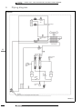
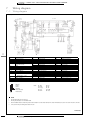
technical data Systems RXQ-M9W1B VRVII Cooling only system • Outdoor Units • VRV COOLING ONLY SYSTEM • RXQ5-10M9W1B TABLE OF CONTENTS RXQ5-10M9W1B s y S y l n O s tm g ei B n tn1 i WUs l9y MoSr 0 o 1 CoI - dI 5 Vt Q RuX ORV 1 3 Specifications. . . . . . . . . . . . . . . . . . . . . . . . . . . . . . . . . . . . . . . . . . . . . . . . . . . . . . . . 2 7 Technical Specifications Electrical Specifications ..............................................2 ..............................................4 2 Options . . . . . . . . . . . . . . . . . . . . . . . . . . . . . . . . . . . . . . . . . . . . . . . . . . . . . . . . . . . . . . . 5 3 Capacity tables . . . . . . . . . . . . . . . . . . . . . . . . . . . . . . . . . . . . . . . . . . . . . . . . . . . . . . 6 Cooling capacity tables ...............................................6 4 Capacity correction factor . . . . . . . . . . . . . . . . . . . . . . . . . . . . . . . . . . . . . . . . . 12 5 Dimensional drawing & centre of gravity . . . . . . . . . . . . . . . . . . . . . . . . 15 Dimensional drawing . . . . . . . . . . . . . . . . . . . . . . . . . . . . . . . . . . . . . . . . . . . . . . . . 15 Centre of gravity . . . . . . . . . . . . . . . . . . . . . . . . . . . . . . . . . . . . . . . . . . . . . . . . . . . . . 17 6 Piping diagram . . . . . . . . . . . . . . . . . . . . . . . . . . . . . . . . . . . . . . . . . . . . . . . . . . . . . 19 7 Wiring diagram . . . . . . . . . . . . . . . . . . . . . . . . . . . . . . . . . . . . . . . . . . . . . . . . . . . . . 21 Wiring diagram . . . . . . . . . . . . . . . . . . . . . . . . . . . . . . . . . . . . . . . . . . . . . . . . . . . . . . 21 External connection diagram . . . . . . . . . . . . . . . . . . . . . . . . . . . . . . . . . . . . . . . . 23 8 Sound level . . . . . . . . . . . . . . . . . . . . . . . . . . . . . . . . . . . . . . . . . . . . . . . . . . . . . . . . . 24 Sound pressure spectrums . . . . . . . . . . . . . . . . . . . . . . . . . . . . . . . . . . . . . . . . . . 24 Sound power spectrums . . . . . . . . . . . . . . . . . . . . . . . . . . . . . . . . . . . . . . . . . . . . . 25 9 Installation . . . . . . . . . . . . . . . . . . . . . . . . . . . . . . . . . . . . . . . . . . . . . . . . . . . . . . . . . . 26 Service space . . . . . . . . . . . . . . . . . . . . . . . . . . . . . . . . . . . . . . . . . . . . . . . . . . . . . . . 26 Fixation and foundation of units . . . . . . . . . . . . . . . . . . . . . . . . . . . . . . . . . . . . . 27 Refrigerant pipe selection . . . . . . . . . . . . . . . . . . . . . . . . . . . . . . . . . . . . . . . . . . . 28 10 Operation range . . . . . . . . . . . . . . . . . . . . . . . . . . . . . . . . . . . . . . . . . . . . . . . . . . . . 30 • VRVII Systems • Outdoor Units 1 • Outdoor Units • VRV COOLING ONLY SYSTEM • RXQ5-10M9W1B 0 o 1 CoI - dI 5 Vt Q RuX V1 OR Specifications 1-1 TECHNICAL SPECIFICATIONS Capacity Cooling Capacity range Power input (Nominal) Cooling RXQ5M9W1B RXQ8M9W1B RXQ10M9W1B kW 14.00 22.40 28.00 HP 5 8 10 kW 4.14 5.92 8.01 Max n° of indoor units to be connected Tot cap index of indoor units to be connected Casing Dimensions 13 16 260 325 Colour Daikin White Material Painted galvanised steel Packing Unit Weight 8 162.5 Height mm 1753 1753 1753 Width mm 796 1055 1055 Depth mm 860 860 860 Height mm 1600 1600 1600 Width mm 635 930 930 Depth mm 765 765 765 Machine Weight kg 141 219 219 Gross Weight kg 156 238 238 mm 1345 1640 1640 54 54 54 2.00 2.00 2.00 Heat Exchanger Dimensions Length Nr of Rows Fin Pitch mm Nr of Passes 1 Face Area m² Nr of Stages 13 16 16 1.598 1.948 1.948 2 2 2 Tube type Fin Hi-XSS (8) Fin type Non-symmetric waffle louvre Treatment Fan Corrosion resistant Type Propeller Quantity Air Flow Rate (nominal) Cooling External static pressure m³/min 1 1 1 75.0 175.0 180.0 Pa 60 Pa in high static pressure Discharge direction Motor Vertical Quantity 1 Model Output motor W 350 Speed rpm 840 Drive Compressor Quantity 750 750 765 785 1 2 2 1 1 1 Model Inverter Type Hermetically sealed scroll compressor Speed rpm Motor Output kW 900 ˜6480 3.0 Starting Method Crankcase W Heater 0.7 1.6 Direct on line 33 33 33 Quantity - 1 1 Model - ON - OFF ON - OFF Type 2 1 Direct drive Quantity Motor 1 Brushless DC - Hermetically sealed scroll compressor Hermetically sealed scroll compressor Speed rpm - 2900 2900 Motor Output kW - 4.5 4.5 Starting Method - Direct on line Direct on line Crankcase W Heater - 33 33 • VRVII Systems • Outdoor Units • Outdoor Units • VRV COOLING ONLY SYSTEM • RXQ5-10M9W1B 1-1 TECHNICAL SPECIFICATIONS Operation Range Cooling Sound Level Cooling Refrigerant RXQ5M9W1B RXQ8M9W1B Min °CDB -5.0 -5.0 -5.0 Max °CDB 43.0 43.0 43.0 Sound Power dBA 72.0 78.0 78.0 Sound Pressure dBA 54.0 57.0 58.0 kg 5.6 Name 7.6 Control 1 1 Name l 1.7 1.6 + 1.7 + 2 Type mm Type Diameter (OD) 9.5 9.5 9.5 Flare connection Braze connection Braze connection mm 15.9 19.1 22.2 m 300 Heat Insulation Max total length 1.6 + 1.7 + 2 Flare connection Diameter (OD) Gas 1 Synthetic (ether) oil Charged Volume Liquid (OD) 8.6 Expansion valve Nr of Circuits Piping connections 3 R-410A Charge Refrigerant Oil RXQ10M9W1B Both liquid and gas pipes 300 Capacity Control Method 300 Inverter controlled Capacity Control 14 to 100 Safety devices HPS Fan motor driver overload protector Inverter overload protector PC board fuse Standard Accessories Standard Accessories Quantity Over current relay 1 1 1 Standard Accessories - Connection pipes Connection pipes Quantity - 3 3 Standard Accessories Quantity Notes Over current relay Installation and operation manual 1 Additional refrigerant label 1 1 1 Nominal cooling capacities are based on : indoor temperature : 27°CDB, 19°CWB, outdoor temperature : 35°CDB, equivalent refrigerant piping : 7.5m, level difference : 0m. Sound power level is an absolute value that a sound source generates. Sound pressure level is a relative value, depending on the distance and acoustic environment. For more details, please refer to sound level drawings. Sound values are measured in a semi-anechoic room. • VRVII Systems • Outdoor Units 3 • Outdoor Units • VRV COOLING ONLY SYSTEM • RXQ5-10M9W1B 1-2 ELECTRICAL SPECIFICATIONS Power Supply RXQ5M9W1B RXQ8M9W1B Name Phase Current Voltage range Wiring connections 3N Frequency Hz 50 50 50 Voltage V 400 400 400 Nominal running Cooling current (RLA) A 6.50 12.00 12.60 Starting current (MSC) A 15.00 71.00 71.00 Minimum circuit amps (MCA) A 12.00 19.50 22.40 Maximum fuse amps (MFA) A 16.00 32.00 32.00 Total overcurrent amps (TOCA) A 14.40 29.80 29.80 Full load amps (FLA) A 0.3 (fan motor) 0.7 (fan motor) 0.7 (fan motor) Minimum V 360 360 360 Maximum V 440 440 440 5 5 5 For Power Supply Quantity For connection with indoor Quantity Remark earth wire include 2 2 Remark 2 P1 - P2 Power Supply Intake Notes RXQ10M9W1B W1 Both indoor and outdoor unit MCA/MFA : MCA = 1.25 x maximum RLA + other RLA + EA FLA, MCA<= 2.25 x maximum RLA + other RLA + EA FLA, next lower standard fuse rating minimum 16A MFA is used to select the circuit breaker and the ground fault circuit interrupter (earth leakage circuit breaker) MSC means the maximum current during start up of the compressor Maximum allowable voltage range variation between phases is 2% RLA is based on following conditions : indoor temperature : 270CDB/190CWB , outdoor temperature : 350CDB Select wire size based on the value of MCA or TOCA 1 TOCA means the total value of each OC set Voltage range : units are suitable for use on electrical systems where voltage supplied to unit terminal is not below or above listed range limits For more details concerning conditional connections, see http://www.daikineurope.com/extranet, select "Daikin Documentation" and select "conditional connection", "the requested product type" and "English" from the drop down lists, click the search button. Finally, click on the document title of your choice. 4 • VRVII Systems • Outdoor Units • Outdoor Units • VRV COOLING ONLY SYSTEM • RXQ5-10M9W1B 2 Options 3 No Item 1 COOL/HEAT SELECTOR RXQ5M RXQ8,10M KRC19-26A 2 FIXING BOX 3 REFNET HEADER KHRQ22M29H KJB111A KHRQ22M29H 4 REFNET JOINT KHRQ22M20T KHRQ22M20T 5 CENTRAL DRAIN PAN KIT KWC26B160 KHRQ22M29T KWC26B280 4TW26671-1 NOTES All options are kits 2 • VRVII Systems • Outdoor Units 5 • Outdoor Units • VRV COOLING ONLY SYSTEM • RXQ5-10M9W1B 3 Capacity tables 3-1 Cooling capacity tables 5HP Combination (%) Capacity index 130% 162.5 120% 150 110% 137.5 100% 125 90% 112.5 3 6 Outdoor air temp. CDB 10 12 14 16 18 20 21 23 25 27 29 31 33 35 37 39 10 12 14 16 18 20 21 23 25 27 29 31 33 35 37 39 10 12 14 16 18 20 21 23 25 27 29 31 33 35 37 39 10 12 14 16 18 20 21 23 25 27 29 31 33 35 37 39 10 12 14 16 18 20 21 23 25 27 29 31 33 35 37 39 14,0 TC kW 12.3 12.3 12.3 12.3 12.3 12.3 12.3 12.3 12.3 12.3 12.3 12.3 12.3 12.3 12.3 12.3 11.3 11.3 11.3 11.3 11.3 11.3 11.3 11.3 11.3 11.3 11.3 11.3 11.3 11.3 11.3 11.3 10.4 10.4 10.4 10.4 10.4 10.4 10.4 10.4 10.4 10.4 10.4 10.4 10.4 10.4 10.4 10.4 9.45 9.45 9.45 9.45 9.45 9.45 9.45 9.45 9.45 9.45 9.45 9.45 9.45 9.45 9.45 9.45 8.50 8.50 8.50 8.50 8.50 8.50 8.50 8.50 8.50 8.50 8.50 8.50 8.50 8.50 8.50 8.50 16,0 PI kW 1.91 1.94 1.98 2.02 2.06 2.10 2.16 2.31 2.47 2.64 2.81 3.00 3.20 3.41 3.63 3.86 1.74 1.77 1.81 1.84 1.88 1.91 1.93 2.06 2.21 2.35 2.51 2.68 2.85 3.03 3.23 3.44 1.58 1.61 1.64 1.67 1.70 1.73 1.75 1.83 1.96 2.09 2.23 2.37 2.52 2.68 2.85 3.03 1.43 1.45 1.48 1.50 1.53 1.56 1.58 1.62 1.73 1.84 1.96 2.09 2.22 2.36 2.50 2.66 1.28 1.30 1.32 1.34 1.37 1.39 1.41 1.43 1.51 1.61 1.71 1.82 1.93 2.05 2.18 2.31 TC kW 14.6 14.6 14.6 14.6 14.6 14.6 14.6 14.6 14.6 14.6 14.6 14.6 14.3 14.1 13.9 13.7 13.5 13.5 13.5 13.5 13.5 13.5 13.5 13.5 13.5 13.5 13.5 13.5 13.5 13.5 13.5 13.5 12.4 12.4 12.4 12.4 12.4 12.4 12.4 12.4 12.4 12.4 12.4 12.4 12.4 12.4 12.4 12.4 11.3 11.3 11.3 11.3 11.3 11.3 11.3 11.3 11.3 11.3 11.3 11.3 11.3 11.3 11.3 11.3 10.1 10.1 10.1 10.1 10.1 10.1 10.1 10.1 10.1 10.1 10.1 10.1 10.1 10.1 10.1 10.1 18,0 PI kW 2.33 2.38 2.42 2.47 2.52 2.68 2.78 2.98 3.19 3.41 3.65 3.86 4.01 4.15 4.30 4.45 2.13 2.17 2.21 2.25 2.30 2.39 2.47 2.65 2.83 3.03 3.24 3.45 3.69 3.93 4.19 4.42 1.93 1.96 2.00 2.04 2.08 2.12 2.18 2.34 2.50 2.67 2.85 3.04 3.24 3.45 3.68 3.92 1.73 1.76 1.79 1.83 1.86 1.90 1.92 2.05 2.19 2.33 2.49 2.65 2.83 3.01 3.20 3.41 1.54 1.57 1.60 1.63 1.66 1.69 1.70 1.78 1.90 2.02 2.15 2.29 2.44 2.60 2.76 2.93 TC kW 17.0 17.0 17.0 16.7 16.5 16.3 16.2 15.9 15.7 15.5 15.2 15.0 14.8 14.6 14.3 14.1 15.7 15.7 15.7 15.7 15.7 15.7 15.7 15.7 15.5 15.2 15.0 14.8 14.5 14.3 14.1 13.9 14.4 14.4 14.4 14.4 14.4 14.4 14.4 14.4 14.4 14.4 14.4 14.4 14.3 14.1 13.8 13.6 13.1 13.1 13.1 13.1 13.1 13.1 13.1 13.1 13.1 13.1 13.1 13.1 13.1 13.1 13.1 13.1 11.8 11.8 11.8 11.8 11.8 11.8 11.8 11.8 11.8 11.8 11.8 11.8 11.8 11.8 11.8 11.8 • VRVII Systems • Outdoor Units PI kW 2.78 2.83 2.86 2.85 2.96 3.10 3.18 3.32 3.47 3.61 3.76 3.90 4.05 4.20 4.35 4.50 2.53 2.58 2.63 2.68 2.77 2.98 3.09 3.30 3.45 3.59 3.74 3.88 4.03 4.17 4.32 4.47 2.29 2.33 2.38 2.42 2.47 2.62 2.71 2.90 3.11 3.33 3.55 3.80 4.00 4.15 4.29 4.44 2.05 2.09 2.13 2.17 2.21 2.28 2.36 2.53 2.70 2.89 3.09 3.29 3.51 3.74 3.99 4.25 1.82 1.85 1.89 1.92 1.96 2.00 2.03 2.18 2.33 2.48 2.65 2.83 3.01 3.21 3.41 3.63 Indoor air temperature: CWB 19,0 TC PI kW kW 17.6 2.83 17.4 2.82 17.2 2.80 16.9 2.83 16.7 2.97 16.5 3.12 16.4 3.19 16.2 3.34 15.9 3.48 15.7 3.63 15.5 3.78 15.2 3.93 15.0 4.07 14.8 4.22 14.6 4.37 14.3 4.53 16.8 2.73 16.8 2.79 16.8 2.84 16.7 2.86 16.5 2.96 16.2 3.10 16.1 3.17 15.9 3.32 15.7 3.46 15.4 3.61 15.2 3.75 15.0 3.90 14.8 4.05 14.5 4.20 14.3 4.35 14.1 4.49 15.4 2.47 15.4 2.52 15.4 2.57 15.4 2.62 15.4 2.69 15.4 2.89 15.4 2.99 15.4 3.21 15.4 3.44 15.2 3.59 14.9 3.73 14.7 3.88 14.5 4.02 14.3 4.17 14.0 4.32 13.8 4.46 14.0 2.21 14.0 2.26 14.0 2.30 14.0 2.34 14.0 2.39 14.0 2.51 14.0 2.60 14.0 2.79 14.0 2.98 14.0 3.19 14.0 3.41 14.0 3.64 14.0 3.88 14.0 4.14 13.8 4.29 13.5 4.43 12.6 1.96 12.6 2.00 12.6 2.04 12.6 2.08 12.6 2.12 12.6 2.16 12.6 2.23 12.6 2.39 12.6 2.56 12.6 2.73 12.6 2.92 12.6 3.11 12.6 3.32 12.6 3.54 12.6 3.77 12.6 4.01 TC: Total capacity: kW ; PI: Power input: kW (Comp. + Outdoor fan motor) 20,0 TC kW 17.9 17.6 17.4 17.2 16.9 16.7 16.6 16.4 16.1 15.9 15.7 15.5 15.2 15.0 14.8 14.6 17.6 17.3 17.1 16.9 16.7 16.4 16.3 16.1 15.9 15.6 15.4 15.2 15.0 14.7 14.5 14.3 16.4 16.4 16.4 16.4 16.4 16.2 16.0 15.8 15.6 15.4 15.1 14.9 14.7 14.4 14.2 14.0 14.9 14.9 14.9 14.9 14.9 14.9 14.9 14.9 14.9 14.9 14.9 14.6 14.4 14.2 13.9 13.7 13.4 13.4 13.4 13.4 13.4 13.4 13.4 13.4 13.4 13.4 13.4 13.4 13.4 13.4 13.4 13.4 22,0 PI kW 2.78 2.76 2.74 2.84 2.99 3.13 3.21 3.35 3.50 3.65 3.80 3.95 4.10 4.25 4.40 4.55 2.85 2.83 2.82 2.83 2.97 3.11 3.19 3.33 3.48 3.63 3.77 3.92 4.07 4.22 4.37 4.52 2.66 2.71 2.76 2.82 2.95 3.09 3.17 3.31 3.46 3.60 3.75 3.89 4.04 4.19 4.34 4.49 2.38 2.43 2.47 2.52 2.57 2.75 2.85 3.06 3.28 3.51 3.72 3.87 4.01 4.16 4.31 4.45 2.11 2.15 2.19 2.23 2.28 2.36 2.45 2.62 2.80 3.00 3.20 3.42 3.64 3.88 4.14 4.41 TC kW 18.3 18.1 17.8 17.6 17.4 17.2 17.0 16.8 16.6 16.4 16.1 15.9 15.7 15.5 15.2 15.0 18.0 17.8 17.5 17.3 17.1 16.8 16.7 16.5 16.3 16.0 15.8 15.6 15.4 15.1 14.9 14.7 17.7 17.4 17.2 17.0 16.8 16.5 16.4 16.2 16.0 15.7 15.5 15.3 15.1 14.8 14.6 14.4 16.7 16.7 16.7 16.7 16.4 16.2 16.1 15.9 15.6 15.4 15.2 15.0 14.7 14.5 14.3 14.1 15.1 15.1 15.1 15.1 15.1 15.1 15.1 15.1 15.1 15.1 14.9 14.7 14.4 14.2 14.0 13.7 24,0 PI kW 2.66 2.64 2.72 2.87 3.02 3.16 3.24 3.39 3.54 3.69 3.84 3.99 4.14 4.30 4.45 4.61 2.74 2.73 2.71 2.85 3.00 3.14 3.22 3.36 3.51 3.66 3.81 3.96 4.11 4.26 4.41 4.57 2.82 2.81 2.79 2.83 2.98 3.12 3.19 3.34 3.49 3.63 3.78 3.93 4.08 4.23 4.38 4.53 2.72 2.77 2.83 2.86 2.96 3.10 3.17 3.32 3.46 3.61 3.75 3.90 4.05 4.19 4.34 4.49 2.41 2.45 2.50 2.55 2.60 2.80 2.90 3.11 3.33 3.56 3.72 3.87 4.01 4.16 4.31 4.46 TC kW 18.7 18.5 18.3 18.1 17.8 17.6 17.5 17.3 17.0 16.8 16.6 16.3 16.1 15.9 15.7 15.4 18.4 18.2 17.9 17.7 17.5 17.3 17.1 16.9 16.7 16.5 16.2 16.0 15.8 15.5 15.3 15.1 18.0 17.8 17.6 17.4 17.1 16.9 16.8 16.6 16.3 16.1 15.9 15.7 15.4 15.2 15.0 14.7 17.7 17.5 17.2 17.0 16.8 16.6 16.4 16.2 16.0 15.8 15.5 15.3 15.1 14.9 14.6 14.4 16.7 16.7 16.7 16.7 16.4 16.2 16.1 15.9 15.6 15.4 15.2 15.0 14.7 14.5 14.3 14.0 PI kW 2.54 2.60 2.75 2.90 3.05 3.20 3.27 3.42 3.57 3.73 3.88 4.03 4.19 4.34 4.50 4.66 2.63 2.62 2.73 2.88 3.02 3.17 3.25 3.40 3.54 3.70 3.85 4.00 4.15 4.31 4.46 4.62 2.73 2.71 2.71 2.85 3.00 3.15 3.22 3.37 3.52 3.67 3.82 3.97 4.12 4.27 4.42 4.58 2.82 2.80 2.79 2.83 2.98 3.12 3.20 3.34 3.49 3.64 3.78 3.93 4.08 4.23 4.38 4.53 2.72 2.77 2.82 2.87 2.96 3.10 3.17 3.32 3.46 3.61 3.75 3.90 4.05 4.19 4.34 4.49 • Outdoor Units • VRV COOLING ONLY SYSTEM • RXQ5-10M9W1B 3 Capacity tables 3-1 Cooling capacity tables 3 5HP Combination (%) Capacity index 80% 100 70% 87.5 60% 75 50% 62.5 Outdoor air temp. CDB 10 12 14 16 18 20 21 23 25 27 29 31 33 35 37 39 10 12 14 16 18 20 21 23 25 27 29 31 33 35 37 39 10 12 14 16 18 20 21 23 25 27 29 31 33 35 37 39 10 12 14 16 18 20 21 23 25 27 29 31 33 35 37 39 14,0 TC kW 7.56 7.56 7.56 7.56 7.56 7.56 7.56 7.56 7.56 7.56 7.56 7.56 7.56 7.56 7.56 7.56 6.61 6.61 6.61 6.61 6.61 6.61 6.61 6.61 6.61 6.61 6.61 6.61 6.61 6.61 6.61 6.61 5.67 5.67 5.67 5.67 5.67 5.67 5.67 5.67 5.67 5.67 5.67 5.67 5.67 5.67 5.67 5.67 4.72 4.72 4.72 4.72 4.72 4.72 4.72 4.72 4.72 4.72 4.72 4.72 4.72 4.72 4.72 4.72 16,0 PI kW 1.13 1.15 1.17 1.19 1.21 1.23 1.24 1.27 1.31 1.39 1.48 1.57 1.67 1.77 1.87 1.98 1.00 1.01 1.03 1.04 1.06 1.08 1.09 1.11 1.13 1.19 1.26 1.34 1.42 1.50 1.59 1.69 0.87 0.88 0.89 0.91 0.92 0.93 0.94 0.96 0.97 1.01 1.07 1.13 1.20 1.26 1.34 1.41 0.75 0.75 0.76 0.78 0.79 0.80 0.80 0.81 0.83 0.84 0.89 0.94 0.99 1.05 1.10 1.16 TC kW 9.02 9.02 9.02 9.02 9.02 9.02 9.02 9.02 9.02 9.02 9.02 9.02 9.02 9.02 9.02 9.02 7.89 7.89 7.89 7.89 7.89 7.89 7.89 7.89 7.89 7.89 7.89 7.89 7.89 7.89 7.89 7.89 6.76 6.76 6.76 6.76 6.76 6.76 6.76 6.76 6.76 6.76 6.76 6.76 6.76 6.76 6.76 6.76 5.63 5.63 5.63 5.63 5.63 5.63 5.63 5.63 5.63 5.63 5.63 5.63 5.63 5.63 5.63 5.63 18,0 PI kW 1.36 1.38 1.40 1.43 1.46 1.48 1.50 1.53 1.63 1.73 1.84 1.96 2.08 2.21 2.35 2.50 1.18 1.20 1.22 1.24 1.27 1.29 1.30 1.32 1.38 1.46 1.56 1.65 1.76 1.86 1.98 2.09 1.02 1.03 1.05 1.07 1.08 1.10 1.11 1.13 1.15 1.22 1.30 1.38 1.46 1.54 1.63 1.73 0.86 0.87 0.89 0.90 0.91 0.93 0.94 0.95 0.97 1.00 1.06 1.12 1.19 1.26 1.33 1.40 TC kW 10.5 10.5 10.5 10.5 10.5 10.5 10.5 10.5 10.5 10.5 10.5 10.5 10.5 10.5 10.5 10.5 9.16 9.16 9.16 9.16 9.16 9.16 9.16 9.16 9.16 9.16 9.16 9.16 9.16 9.16 9.16 9.16 7.85 7.85 7.85 7.85 7.85 7.85 7.85 7.85 7.85 7.85 7.85 7.85 7.85 7.85 7.85 7.85 6.54 6.54 6.54 6.54 6.54 6.54 6.54 6.54 6.54 6.54 6.54 6.54 6.54 6.54 6.54 6.54 PI kW 1.59 1.62 1.65 1.68 1.72 1.75 1.77 1.85 1.98 2.11 2.25 2.40 2.55 2.71 2.88 3.07 1.38 1.40 1.43 1.46 1.48 1.51 1.52 1.56 1.66 1.77 1.88 2.00 2.13 2.26 2.40 2.55 1.18 1.20 1.22 1.24 1.26 1.28 1.29 1.32 1.37 1.46 1.55 1.65 1.75 1.85 1.96 2.08 0.99 1.00 1.02 1.03 1.05 1.07 1.08 1.10 1.12 1.18 1.25 1.32 1.40 1.49 1.57 1.66 Indoor air temperature: CWB 19,0 TC PI kW kW 11.2 1.72 11.2 1.75 11.2 1.78 11.2 1.82 11.2 1.85 11.2 1.89 11.2 1.91 11.2 2.03 11.2 2.17 11.2 2.31 11.2 2.47 11.2 2.63 11.2 2.80 11.2 2.98 11.2 3.17 11.2 3.38 9.80 1.48 9.80 1.51 9.80 1.54 9.80 1.57 9.80 1.59 9.80 1.63 9.80 1.64 9.80 1.70 9.80 1.81 9.80 1.93 9.80 2.06 9.80 2.19 9.80 2.33 9.80 2.48 9.80 2.63 9.80 2.80 8.40 1.26 8.40 1.28 8.40 1.30 8.40 1.33 8.40 1.35 8.40 1.38 8.40 1.39 8.40 1.41 8.40 1.49 8.40 1.58 8.40 1.68 8.40 1.79 8.40 1.90 8.40 2.02 8.40 2.14 8.40 2.27 7.00 1.05 7.00 1.07 7.00 1.09 7.00 1.10 7.00 1.12 7.00 1.14 7.00 1.15 7.00 1.17 7.00 1.20 7.00 1.27 7.00 1.35 7.00 1.43 7.00 1.52 7.00 1.61 7.00 1.70 7.00 1.80 TC: Total capacity: kW ; PI: Power input: kW (Comp. + Outdoor fan motor) 20,0 TC kW 11.9 11.9 11.9 11.9 11.9 11.9 11.9 11.9 11.9 11.9 11.9 11.9 11.9 11.9 11.9 11.9 10.4 10.4 10.4 10.4 10.4 10.4 10.4 10.4 10.4 10.4 10.4 10.4 10.4 10.4 10.4 10.4 8.95 8.95 8.95 8.95 8.95 8.95 8.95 8.95 8.95 8.95 8.95 8.95 8.95 8.95 8.95 8.95 7.46 7.46 7.46 7.46 7.46 7.46 7.46 7.46 7.46 7.46 7.46 7.46 7.46 7.46 7.46 7.46 22,0 PI kW 1.84 1.88 1.91 1.95 1.99 2.03 2.07 2.21 2.37 2.53 2.70 2.88 3.07 3.26 3.48 3.70 1.59 1.62 1.65 1.68 1.71 1.74 1.76 1.84 1.97 2.10 2.24 2.39 2.54 2.70 2.87 3.05 1.35 1.37 1.39 1.42 1.44 1.47 1.49 1.51 1.61 1.71 1.82 1.94 2.06 2.19 2.33 2.47 1.12 1.14 1.15 1.17 1.19 1.22 1.23 1.25 1.29 1.37 1.45 1.54 1.64 1.74 1.84 1.95 TC kW 13.4 13.4 13.4 13.4 13.4 13.4 13.4 13.4 13.4 13.4 13.4 13.4 13.4 13.4 13.4 13.4 11.7 11.7 11.7 11.7 11.7 11.7 11.7 11.7 11.7 11.7 11.7 11.7 11.7 11.7 11.7 11.7 10.0 10.0 10.0 10.0 10.0 10.0 10.0 10.0 10.0 10.0 10.0 10.0 10.0 10.0 10.0 10.0 8.37 8.37 8.37 8.37 8.37 8.37 8.37 8.37 8.37 8.37 8.37 8.37 8.37 8.37 8.37 8.37 24,0 PI kW 2.10 2.14 2.18 2.23 2.27 2.35 2.44 2.61 2.79 2.99 3.19 3.40 3.63 3.87 4.12 4.39 1.81 1.84 1.87 1.91 1.95 1.99 2.02 2.16 2.31 2.46 2.63 2.80 2.99 3.18 3.38 3.60 1.52 1.55 1.58 1.61 1.64 1.67 1.69 1.75 1.87 1.99 2.12 2.26 2.41 2.56 2.72 2.89 1.26 1.28 1.30 1.32 1.35 1.37 1.38 1.41 1.48 1.57 1.68 1.78 1.89 2.01 2.13 2.26 TC kW 14.8 14.8 14.8 14.8 14.8 14.8 14.8 14.8 14.8 14.8 14.8 14.6 14.4 14.2 13.9 13.7 13.0 13.0 13.0 13.0 13.0 13.0 13.0 13.0 13.0 13.0 13.0 13.0 13.0 13.0 13.0 13.0 11.1 11.1 11.1 11.1 11.1 11.1 11.1 11.1 11.1 11.1 11.1 11.1 11.1 11.1 11.1 11.1 9.28 9.28 9.28 9.28 9.28 9.28 9.28 9.28 9.28 9.28 9.28 9.28 9.28 9.28 9.28 9.28 PI kW 2.37 2.41 2.46 2.51 2.56 2.74 2.83 3.04 3.25 3.48 3.72 3.87 4.01 4.16 4.30 4.45 2.03 2.07 2.11 2.15 2.19 2.25 2.33 2.50 2.67 2.86 3.05 3.25 3.47 3.70 3.94 4.20 1.71 1.74 1.77 1.80 1.84 1.87 1.89 2.01 2.15 2.29 2.45 2.61 2.78 2.96 3.15 3.35 1.40 1.42 1.45 1.47 1.50 1.53 1.54 1.58 1.69 1.80 1.91 2.03 2.16 2.30 2.44 2.59 3 NOTES 1 The above table shows the average value of conditions which may occur. • VRVII Systems • Outdoor Units 7 • Outdoor Units • VRV COOLING ONLY SYSTEM • RXQ5-10M9W1B 3 Capacity tables 3-1 Cooling capacity tables 8HP 3 8 Combination (%) Capacity index 130% 260 120% 240 110% 220 100% 200 90% 180 Outdoor air temp. CDB 10 12 14 16 18 20 21 23 25 27 29 31 33 35 37 39 10 12 14 16 18 20 21 23 25 27 29 31 33 35 37 39 10 12 14 16 18 20 21 23 25 27 29 31 33 35 37 39 10 12 14 16 18 20 21 23 25 27 29 31 33 35 37 39 10 12 14 16 18 20 21 23 25 27 29 31 33 35 37 39 14,0 TC kW 19.7 19.7 19.7 19.7 19.7 19.7 19.7 19.7 19.7 19.7 19.7 19.7 19.7 19.7 19.7 19.7 18.1 18.1 18.1 18.1 18.1 18.1 18.1 18.1 18.1 18.1 18.1 18.1 18.1 18.1 18.1 18.1 16.6 16.6 16.6 16.6 16.6 16.6 16.6 16.6 16.6 16.6 16.6 16.6 16.6 16.6 16.6 16.6 15.1 15.1 15.1 15.1 15.1 15.1 15.1 15.1 15.1 15.1 15.1 15.1 15.1 15.1 15.1 15.1 13.6 13.6 13.6 13.6 13.6 13.6 13.6 13.6 13.6 13.6 13.6 13.6 13.6 13.6 13.6 13.6 16,0 PI kW 2.73 2.78 2.83 2.88 2.94 3.00 3.08 3.30 3.53 3.77 4.02 4.29 4.57 4.87 5.19 5.52 2.49 2.54 2.58 2.63 2.68 2.74 2.76 2.95 3.15 3.37 3.59 3.83 4.08 4.34 4.62 4.91 2.26 2.30 2.34 2.39 2.43 2.48 2.51 2.62 2.80 2.99 3.18 3.39 3.61 3.84 4.08 4.34 2.04 2.08 2.11 2.15 2.19 2.23 2.25 2.31 2.47 2.63 2.80 2.98 3.17 3.37 3.58 3.80 1.83 1.86 1.89 1.92 1.96 1.99 2.01 2.05 2.16 2.30 2.45 2.60 2.76 2.93 3.11 3.30 TC kW 23.4 23.4 23.4 23.4 23.4 23.4 23.4 23.4 23.4 23.4 23.4 23.3 23.0 22.6 22.2 21.9 21.6 21.6 21.6 21.6 21.6 21.6 21.6 21.6 21.6 21.6 21.6 21.6 21.6 21.6 21.6 21.5 19.8 19.8 19.8 19.8 19.8 19.8 19.8 19.8 19.8 19.8 19.8 19.8 19.8 19.8 19.8 19.8 18.0 18.0 18.0 18.0 18.0 18.0 18.0 18.0 18.0 18.0 18.0 18.0 18.0 18.0 18.0 18.0 16.2 16.2 16.2 16.2 16.2 16.2 16.2 16.2 16.2 16.2 16.2 16.2 16.2 16.2 16.2 16.2 18,0 PI kW 3.34 3.40 3.46 3.53 3.60 3.84 3.98 4.26 4.56 4.88 5.22 5.52 5.73 5.94 6.15 6.36 3.04 3.10 3.16 3.22 3.28 3.41 3.54 3.79 4.05 4.33 4.63 4.94 5.27 5.62 5.99 6.32 2.75 2.81 2.86 2.91 2.97 3.03 3.12 3.34 3.58 3.82 4.08 4.35 4.63 4.94 5.26 5.60 2.47 2.52 2.57 2.61 2.66 2.72 2.74 2.93 3.13 3.34 3.56 3.79 4.04 4.30 4.58 4.87 2.20 2.24 2.28 2.32 2.37 2.41 2.44 2.54 2.71 2.89 3.08 3.28 3.49 3.71 3.95 4.19 TC kW 27.2 27.2 27.1 26.8 26.4 26.0 25.9 25.5 25.1 24.8 24.4 24.0 23.7 23.3 22.9 22.6 25.1 25.1 25.1 25.1 25.1 25.1 25.1 25.1 24.7 24.4 24.0 23.6 23.3 22.9 22.5 22.2 23.0 23.0 23.0 23.0 23.0 23.0 23.0 23.0 23.0 23.0 23.0 23.0 22.9 22.5 22.2 21.8 20.9 20.9 20.9 20.9 20.9 20.9 20.9 20.9 20.9 20.9 20.9 20.9 20.9 20.9 20.9 20.9 18.8 18.8 18.8 18.8 18.8 18.8 18.8 18.8 18.8 18.8 18.8 18.8 18.8 18.8 18.8 18.8 • VRVII Systems • Outdoor Units PI kW 3.97 4.04 4.09 4.07 4.23 4.44 4.54 4.75 4.96 5.16 5.37 5.58 5.79 6.01 6.22 6.43 3.62 3.69 3.76 3.83 3.96 4.26 4.41 4.72 4.93 5.13 5.34 5.55 5.76 5.97 6.18 6.39 3.27 3.33 3.40 3.46 3.53 3.74 3.87 4.15 4.45 4.76 5.08 5.43 5.72 5.93 6.14 6.35 2.93 2.99 3.04 3.10 3.16 3.26 3.37 3.61 3.87 4.13 4.41 4.71 5.02 5.35 5.70 6.07 2.60 2.65 2.70 2.75 2.80 2.86 2.91 3.11 3.33 3.55 3.79 4.04 4.31 4.59 4.88 5.19 Indoor air temperature: CWB 19,0 TC PI kW kW 28.2 4.05 27.8 4.03 27.5 4.01 27.1 4.05 26.8 4.25 26.4 4.46 26.2 4.56 25.8 4.77 25.5 4.98 25.1 5.19 24.8 5.40 24.4 5.61 24.0 5.83 23.7 6.04 23.3 6.26 22.9 6.47 26.9 3.91 26.9 3.98 26.9 4.06 26.7 4.09 26.3 4.23 26.0 4.43 25.8 4.54 25.4 4.74 25.1 4.95 24.7 5.16 24.3 5.37 24.0 5.58 23.6 5.79 23.2 6.00 22.9 6.21 22.5 6.43 24.6 3.54 24.6 3.60 24.6 3.67 24.6 3.74 24.6 3.85 24.6 4.13 24.6 4.28 24.6 4.59 24.6 4.92 24.3 5.13 23.9 5.33 23.5 5.54 23.2 5.75 22.8 5.96 22.5 6.17 22.1 6.38 22.4 3.17 22.4 3.23 22.4 3.29 22.4 3.35 22.4 3.42 22.4 3.59 22.4 3.72 22.4 3.99 22.4 4.27 22.4 4.56 22.4 4.87 22.4 5.20 22.4 5.55 22.4 5.92 22.0 6.13 21.7 6.34 20.2 2.81 20.2 2.86 20.2 2.91 20.2 2.97 20.2 3.03 20.2 3.09 20.2 3.20 20.2 3.42 20.2 3.66 20.2 3.91 20.2 4.17 20.2 4.45 20.2 4.75 20.2 5.06 20.2 5.39 20.2 5.74 TC: Total capacity: kW ; PI: Power input: kW (Comp. + Outdoor fan motor) 20,0 TC kW 28.6 28.2 27.8 27.5 27.1 26.7 26.6 26.2 25.8 25.5 25.1 24.7 24.4 24.0 23.6 23.3 28.1 27.8 27.4 27.0 26.7 26.3 26.1 25.8 25.4 25.0 24.7 24.3 23.9 23.6 23.2 22.8 26.2 26.2 26.2 26.2 26.2 25.9 25.7 25.3 24.9 24.6 24.2 23.8 23.5 23.1 22.8 22.4 23.9 23.9 23.9 23.9 23.9 23.9 23.9 23.9 23.9 23.9 23.8 23.4 23.0 22.7 22.3 21.9 21.5 21.5 21.5 21.5 21.5 21.5 21.5 21.5 21.5 21.5 21.5 21.5 21.5 21.5 21.5 21.5 22,0 PI kW 3.97 3.95 3.92 4.06 4.27 4.48 4.59 4.80 5.01 5.22 5.43 5.64 5.86 6.07 6.29 6.51 4.07 4.05 4.03 4.04 4.25 4.45 4.56 4.77 4.97 5.18 5.39 5.61 5.82 6.03 6.25 6.46 3.80 3.88 3.95 4.03 4.22 4.43 4.53 4.73 4.94 5.15 5.36 5.57 5.78 5.99 6.20 6.41 3.41 3.47 3.54 3.61 3.68 3.94 4.08 4.38 4.69 5.01 5.32 5.53 5.74 5.95 6.16 6.37 3.02 3.07 3.13 3.19 3.25 3.38 3.50 3.75 4.01 4.29 4.58 4.88 5.21 5.55 5.92 6.31 TC kW 29.3 28.9 28.5 28.2 27.8 27.5 27.3 26.9 26.5 26.2 25.8 25.4 25.1 24.7 24.4 24.0 28.8 28.4 28.0 27.7 27.3 27.0 26.8 26.4 26.0 25.7 25.3 24.9 24.6 24.2 23.9 23.5 28.3 27.9 27.5 27.2 26.8 26.5 26.3 25.9 25.5 25.2 24.8 24.4 24.1 23.7 23.4 23.0 26.8 26.8 26.8 26.7 26.3 26.0 25.8 25.4 25.0 24.7 24.3 23.9 23.6 23.2 22.9 22.5 24.1 24.1 24.1 24.1 24.1 24.1 24.1 24.1 24.1 24.1 23.8 23.4 23.1 22.7 22.4 22.0 24,0 PI kW 3.80 3.78 3.89 4.10 4.31 4.53 4.63 4.84 5.06 5.27 5.49 5.71 5.92 6.14 6.36 6.59 3.92 3.90 3.87 4.08 4.28 4.49 4.60 4.81 5.02 5.23 5.45 5.66 5.88 6.09 6.31 6.53 4.04 4.02 4.00 4.05 4.26 4.46 4.57 4.78 4.99 5.20 5.41 5.62 5.83 6.05 6.26 6.48 3.89 3.97 4.04 4.10 4.23 4.43 4.53 4.74 4.95 5.16 5.37 5.58 5.79 6.00 6.21 6.43 3.44 3.51 3.58 3.65 3.72 4.00 4.14 4.44 4.76 5.09 5.33 5.53 5.74 5.95 6.16 6.37 TC kW 30.0 29.6 29.3 28.9 28.5 28.2 28.0 27.6 27.3 26.9 26.5 26.2 25.8 25.4 25.1 24.7 29.4 29.1 28.7 28.3 28.0 27.6 27.4 27.1 26.7 26.3 26.0 25.6 25.2 24.9 24.5 24.1 28.9 28.5 28.1 27.8 27.4 27.1 26.9 26.5 26.1 25.8 25.4 25.0 24.7 24.3 24.0 23.6 28.3 28.0 27.6 27.2 26.9 26.5 26.3 25.9 25.6 25.2 24.9 24.5 24.1 23.8 23.4 23.0 26.7 26.7 26.7 26.7 26.3 25.9 25.8 25.4 25.0 24.7 24.3 23.9 23.6 23.2 22.8 22.5 PI kW 3.63 3.72 3.93 4.14 4.36 4.57 4.68 4.89 5.11 5.33 5.55 5.77 5.99 6.21 6.44 6.66 3.77 3.74 3.90 4.11 4.32 4.54 4.64 4.85 5.07 5.28 5.50 5.72 5.94 6.16 6.38 6.60 3.90 3.87 3.87 4.08 4.29 4.50 4.61 4.82 5.03 5.24 5.46 5.67 5.89 6.10 6.32 6.54 4.03 4.01 3.99 4.05 4.26 4.47 4.57 4.78 4.99 5.20 5.41 5.62 5.84 6.05 6.27 6.48 3.88 3.96 4.03 4.10 4.23 4.43 4.53 4.74 4.95 5.16 5.37 5.58 5.79 6.00 6.21 6.42 • Outdoor Units • VRV COOLING ONLY SYSTEM • RXQ5-10M9W1B 3 Capacity tables 3-1 Cooling capacity tables 3 8HP Combination (%) Capacity index 80% 160 70% 140 60% 120 50% 100 Outdoor air temp. CDB 10 12 14 16 18 20 21 23 25 27 29 31 33 35 37 39 10 12 14 16 18 20 21 23 25 27 29 31 33 35 37 39 10 12 14 16 18 20 21 23 25 27 29 31 33 35 37 39 10 12 14 16 18 20 21 23 25 27 29 31 33 35 37 39 14,0 TC kW 12.1 12.1 12.1 12.1 12.1 12.1 12.1 12.1 12.1 12.1 12.1 12.1 12.1 12.1 12.1 12.1 10.6 10.6 10.6 10.6 10.6 10.6 10.6 10.6 10.6 10.6 10.6 10.6 10.6 10.6 10.6 10.6 9.1 9.1 9.1 9.1 9.1 9.1 9.1 9.1 9.1 9.1 9.1 9.1 9.1 9.1 9.1 9.1 7.56 7.56 7.56 7.56 7.56 7.56 7.56 7.56 7.56 7.56 7.56 7.56 7.56 7.56 7.56 7.56 16,0 PI kW 1.62 1.65 1.67 1.70 1.73 1.76 1.78 1.81 1.87 1.99 2.11 2.24 2.38 2.53 2.68 2.84 1.43 1.45 1.47 1.49 1.52 1.54 1.56 1.58 1.61 1.70 1.81 1.92 2.03 2.15 2.28 2.41 1.24 1.26 1.28 1.29 1.31 1.34 1.35 1.37 1.39 1.44 1.53 1.62 1.71 1.81 1.91 2.02 1.07 1.08 1.09 1.11 1.12 1.14 1.15 1.17 1.18 1.20 1.27 1.34 1.42 1.50 1.58 1.67 TC kW 14.4 14.4 14.4 14.4 14.4 14.4 14.4 14.4 14.4 14.4 14.4 14.4 14.4 14.4 14.4 14.4 12.6 12.6 12.6 12.6 12.6 12.6 12.6 12.6 12.6 12.6 12.6 12.6 12.6 12.6 12.6 12.6 10.8 10.8 10.8 10.8 10.8 10.8 10.8 10.8 10.8 10.8 10.8 10.8 10.8 10.8 10.8 10.8 9.0 9.0 9.0 9.0 9.0 9.0 9.0 9.0 9.0 9.0 9.0 9.0 9.0 9.0 9.0 9.0 18,0 PI kW 1.94 1.97 2.01 2.04 2.08 2.12 2.14 2.18 2.32 2.48 2.64 2.80 2.98 3.17 3.36 3.57 1.69 1.72 1.75 1.78 1.81 1.84 1.86 1.89 1.97 2.09 2.23 2.37 2.51 2.66 2.83 3.00 1.46 1.48 1.50 1.53 1.55 1.58 1.59 1.62 1.65 1.75 1.85 1.97 2.08 2.21 2.34 2.47 1.23 1.25 1.27 1.29 1.31 1.33 1.34 1.36 1.38 1.43 1.52 1.61 1.70 1.80 1.90 2.01 TC kW 16.8 16.8 16.8 16.8 16.8 16.8 16.8 16.8 16.8 16.8 16.8 16.8 16.8 16.8 16.8 16.8 14.7 14.7 14.7 14.7 14.7 14.7 14.7 14.7 14.7 14.7 14.7 14.7 14.7 14.7 14.7 14.7 12.6 12.6 12.6 12.6 12.6 12.6 12.6 12.6 12.6 12.6 12.6 12.6 12.6 12.6 12.6 12.6 10.5 10.5 10.5 10.5 10.5 10.5 10.5 10.5 10.5 10.5 10.5 10.5 10.5 10.5 10.5 10.5 PI kW 2.28 2.32 2.36 2.41 2.45 2.50 2.53 2.65 2.83 3.02 3.22 3.43 3.65 3.88 4.13 4.39 1.97 2.01 2.04 2.08 2.12 2.16 2.18 2.22 2.37 2.53 2.69 2.86 3.04 3.23 3.43 3.65 1.68 1.71 1.74 1.77 1.80 1.83 1.85 1.88 1.96 2.08 2.21 2.35 2.50 2.65 2.81 2.98 1.41 1.43 1.46 1.48 1.50 1.53 1.54 1.57 1.60 1.68 1.79 1.89 2.01 2.13 2.25 2.38 Indoor air temperature: CWB 19,0 TC PI kW kW 17.9 2.46 17.9 2.50 17.9 2.55 17.9 2.60 17.9 2.65 17.9 2.70 17.9 2.73 17.9 2.90 17.9 3.10 17.9 3.31 17.9 3.53 17.9 3.76 17.9 4.01 17.9 4.26 17.9 4.54 17.9 4.83 15.7 2.12 15.7 2.16 15.7 2.20 15.7 2.24 15.7 2.28 15.7 2.32 15.7 2.35 15.7 2.43 15.7 2.59 15.7 2.76 15.7 2.94 15.7 3.13 15.7 3.33 15.7 3.54 15.7 3.76 15.7 4.00 13.4 1.80 13.4 1.83 13.4 1.86 13.4 1.90 13.4 1.93 13.4 1.97 13.4 1.99 13.4 2.02 13.4 2.13 13.4 2.26 13.4 2.41 13.4 2.56 13.4 2.72 13.4 2.89 13.4 3.06 13.4 3.25 11.2 1.50 11.2 1.53 11.2 1.55 11.2 1.58 11.2 1.60 11.2 1.63 11.2 1.65 11.2 1.68 11.2 1.71 11.2 1.82 11.2 1.93 11.2 2.05 11.2 2.17 11.2 2.30 11.2 2.44 11.2 2.58 TC: Total capacity: kW ; PI: Power input: kW (Comp. + Outdoor fan motor) 20,0 TC kW 19.1 19.1 19.1 19.1 19.1 19.1 19.1 19.1 19.1 19.1 19.1 19.1 19.1 19.1 19.1 19.1 16.7 16.7 16.7 16.7 16.7 16.7 16.7 16.7 16.7 16.7 16.7 16.7 16.7 16.7 16.7 16.7 14.3 14.3 14.3 14.3 14.3 14.3 14.3 14.3 14.3 14.3 14.3 14.3 14.3 14.3 14.3 14.3 11.9 11.9 11.9 11.9 11.9 11.9 11.9 11.9 11.9 11.9 11.9 11.9 11.9 11.9 11.9 11.9 22,0 PI kW 2.64 2.69 2.74 2.79 2.84 2.90 2.96 3.17 3.39 3.62 3.86 4.11 4.38 4.67 4.97 5.29 2.27 2.31 2.36 2.40 2.44 2.49 2.52 2.64 2.82 3.00 3.20 3.41 3.63 3.86 4.11 4.37 1.93 1.96 1.99 2.03 2.07 2.10 2.12 2.17 2.30 2.45 2.61 2.78 2.95 3.13 3.33 3.53 1.60 1.62 1.65 1.68 1.71 1.74 1.75 1.79 1.84 1.96 2.08 2.21 2.34 2.48 2.63 2.79 TC kW 21.4 21.4 21.4 21.4 21.4 21.4 21.4 21.4 21.4 21.4 21.4 21.4 21.4 21.4 21.4 21.4 18.7 18.7 18.7 18.7 18.7 18.7 18.7 18.7 18.7 18.7 18.7 18.7 18.7 18.7 18.7 18.7 16.1 16.1 16.1 16.1 16.1 16.1 16.1 16.1 16.1 16.1 16.1 16.1 16.1 16.1 16.1 16.1 13.4 13.4 13.4 13.4 13.4 13.4 13.4 13.4 13.4 13.4 13.4 13.4 13.4 13.4 13.4 13.4 24,0 PI kW 3.01 3.06 3.12 3.18 3.24 3.36 3.48 3.73 3.99 4.27 4.56 4.87 5.19 5.53 5.90 6.28 2.58 2.63 2.68 2.73 2.78 2.84 2.88 3.09 3.30 3.52 3.76 4.01 4.27 4.55 4.84 5.15 2.18 2.22 2.26 2.30 2.34 2.39 2.41 2.50 2.67 2.85 3.04 3.23 3.44 3.66 3.89 4.13 1.80 1.83 1.86 1.89 1.92 1.96 1.98 2.01 2.12 2.25 2.40 2.55 2.70 2.87 3.05 3.23 TC kW 23.7 23.7 23.7 23.7 23.7 23.7 23.7 23.7 23.7 23.7 23.7 23.4 23.0 22.7 22.3 21.9 20.8 20.8 20.8 20.8 20.8 20.8 20.8 20.8 20.8 20.8 20.8 20.8 20.8 20.8 20.8 20.8 17.8 17.8 17.8 17.8 17.8 17.8 17.8 17.8 17.8 17.8 17.8 17.8 17.8 17.8 17.8 17.8 14.8 14.8 14.8 14.8 14.8 14.8 14.8 14.8 14.8 14.8 14.8 14.8 14.8 14.8 14.8 14.8 PI kW 3.39 3.45 3.52 3.59 3.66 3.91 4.05 4.35 4.65 4.98 5.32 5.53 5.74 5.94 6.15 6.36 2.90 2.96 3.01 3.07 3.13 3.22 3.34 3.57 3.82 4.08 4.36 4.65 4.96 5.29 5.63 6.00 2.44 2.48 2.53 2.58 2.63 2.68 2.71 2.88 3.07 3.28 3.50 3.73 3.97 4.23 4.50 4.78 2.00 2.03 2.07 2.11 2.15 2.19 2.21 2.26 2.41 2.57 2.74 2.91 3.09 3.29 3.49 3.71 3 NOTES 1 The above table shows the average value of conditions which may occur. • VRVII Systems • Outdoor Units 9 • Outdoor Units • VRV COOLING ONLY SYSTEM • RXQ5-10M9W1B 3 Capacity tables 3-1 Cooling capacity tables 10HP 3 10 Combination (%) Capacity index 130% 325 120% 300 110% 275 100% 250 90% 225 Outdoor air temp. CDB 10 12 14 16 18 20 21 23 25 27 29 31 33 35 37 39 10 12 14 16 18 20 21 23 25 27 29 31 33 35 37 39 10 12 14 16 18 20 21 23 25 27 29 31 33 35 37 39 10 12 14 16 18 20 21 23 25 27 29 31 33 35 37 39 10 12 14 16 18 20 21 23 25 27 29 31 33 35 37 39 14,0 TC kW 24.6 24.6 24.6 24.6 24.6 24.6 24.6 24.6 24.6 24.6 24.6 24.6 24.6 24.6 24.6 24.6 22.7 22.7 22.7 22.7 22.7 22.7 22.7 22.7 22.7 22.7 22.7 22.7 22.7 22.7 22.7 22.7 20.8 20.8 20.8 20.8 20.8 20.8 20.8 20.8 20.8 20.8 20.8 20.8 20.8 20.8 20.8 20.8 18.9 18.9 18.9 18.9 18.9 18.9 18.9 18.9 18.9 18.9 18.9 18.9 18.9 18.9 18.9 18.9 17.0 17.0 17.0 17.0 17.0 17.0 17.0 17.0 17.0 17.0 17.0 17.0 17.0 17.0 17.0 17.0 16,0 PI kW 3.69 3.76 3.83 3.90 3.98 4.06 4.17 4.46 4.77 5.10 5.44 5.81 6.19 6.59 7.02 7.47 3.37 3.43 3.50 3.56 3.63 3.70 3.74 3.99 4.27 4.56 4.86 5.18 5.52 5.87 6.25 6.65 3.06 3.12 3.17 3.23 3.29 3.36 3.39 3.55 3.79 4.04 4.31 4.59 4.88 5.19 5.52 5.87 2.76 2.81 2.86 2.91 2.96 3.02 3.05 3.13 3.34 3.56 3.79 4.03 4.29 4.56 4.84 5.14 2.47 2.51 2.56 2.60 2.65 2.70 2.72 2.77 2.92 3.11 3.31 3.52 3.74 3.97 4.21 4.47 TC kW 29.3 29.3 29.3 29.3 29.3 29.3 29.3 29.3 29.3 29.3 29.3 29.2 28.7 28.2 27.8 27.3 27.0 27.0 27.0 27.0 27.0 27.0 27.0 27.0 27.0 27.0 27.0 27.0 27.0 27.0 27.0 26.9 24.8 24.8 24.8 24.8 24.8 24.8 24.8 24.8 24.8 24.8 24.8 24.8 24.8 24.8 24.8 24.8 22.5 22.5 22.5 22.5 22.5 22.5 22.5 22.5 22.5 22.5 22.5 22.5 22.5 22.5 22.5 22.5 20.3 20.3 20.3 20.3 20.3 20.3 20.3 20.3 20.3 20.3 20.3 20.3 20.3 20.3 20.3 20.3 18,0 PI kW 4.51 4.60 4.69 4.78 4.87 5.19 5.38 5.77 6.17 6.60 7.06 7.47 7.75 8.04 8.32 8.60 4.12 4.19 4.27 4.36 4.44 4.62 4.78 5.13 5.48 5.86 6.26 6.68 7.13 7.60 8.10 8.55 3.73 3.80 3.87 3.94 4.02 4.10 4.22 4.52 4.84 5.17 5.52 5.88 6.27 6.68 7.11 7.57 3.35 3.41 3.47 3.54 3.61 3.68 3.71 3.96 4.23 4.52 4.82 5.13 5.47 5.82 6.19 6.59 2.98 3.03 3.09 3.14 3.20 3.27 3.30 3.43 3.67 3.91 4.17 4.44 4.72 5.02 5.34 5.67 TC kW 34.0 34.0 33.9 33.5 33.0 32.5 32.3 31.9 31.4 31.0 30.5 30.0 29.6 29.1 28.7 28.2 31.4 31.4 31.4 31.4 31.4 31.4 31.4 31.4 30.9 30.5 30.0 29.5 29.1 28.6 28.2 27.7 28.8 28.8 28.8 28.8 28.8 28.8 28.8 28.8 28.8 28.8 28.8 28.8 28.6 28.1 27.7 27.2 26.2 26.2 26.2 26.2 26.2 26.2 26.2 26.2 26.2 26.2 26.2 26.2 26.2 26.2 26.2 26.2 23.6 23.6 23.6 23.6 23.6 23.6 23.6 23.6 23.6 23.6 23.6 23.6 23.6 23.6 23.6 23.6 • VRVII Systems • Outdoor Units PI kW 5.37 5.47 5.54 5.51 5.73 6.00 6.14 6.42 6.70 6.99 7.27 7.55 7.84 8.13 8.42 8.71 4.89 4.99 5.08 5.18 5.36 5.76 5.97 6.39 6.67 6.95 7.23 7.51 7.79 8.08 8.36 8.65 4.43 4.51 4.60 4.68 4.78 5.06 5.24 5.62 6.02 6.44 6.88 7.34 7.74 8.03 8.31 8.59 3.97 4.04 4.12 4.20 4.28 4.41 4.56 4.89 5.23 5.59 5.97 6.37 6.79 7.24 7.71 8.22 3.52 3.58 3.65 3.72 3.79 3.87 3.93 4.21 4.50 4.81 5.13 5.47 5.83 6.20 6.60 7.03 Indoor air temperature: CWB 19,0 TC PI kW kW 35.3 5.48 34.8 5.45 34.4 5.43 33.9 5.47 33.4 5.75 33.0 6.03 32.8 6.17 32.3 6.46 31.8 6.74 31.4 7.02 30.9 7.31 30.5 7.60 30.0 7.88 29.6 8.17 29.1 8.46 28.7 8.76 33.6 5.29 33.6 5.39 33.6 5.49 33.4 5.53 32.9 5.72 32.5 6.00 32.2 6.14 31.8 6.42 31.3 6.70 30.9 6.98 30.4 7.26 30.0 7.55 29.5 7.83 29.0 8.12 28.6 8.41 28.1 8.70 30.8 4.78 30.8 4.87 30.8 4.97 30.8 5.06 30.8 5.20 30.8 5.59 30.8 5.79 30.8 6.21 30.8 6.66 30.3 6.94 29.9 7.22 29.4 7.50 29.0 7.78 28.5 8.06 28.1 8.35 27.6 8.64 28.0 4.28 28.0 4.36 28.0 4.45 28.0 4.53 28.0 4.62 28.0 4.86 28.0 5.03 28.0 5.39 28.0 5.77 28.0 6.17 28.0 6.59 28.0 7.04 28.0 7.51 28.0 8.01 27.5 8.29 27.1 8.58 25.2 3.80 25.2 3.87 25.2 3.94 25.2 4.02 25.2 4.10 25.2 4.18 25.2 4.32 25.2 4.63 25.2 4.95 25.2 5.29 25.2 5.65 25.2 6.02 25.2 6.42 25.2 6.84 25.2 7.29 25.2 7.76 TC: Total capacity: kW ; PI: Power input: kW (Comp. + Outdoor fan motor) 20,0 TC kW 35.7 35.3 34.8 34.3 33.9 33.4 33.2 32.7 32.3 31.8 31.4 30.9 30.5 30.0 29.6 29.1 35.2 34.7 34.2 33.8 33.3 32.9 32.6 32.2 31.7 31.3 30.8 30.4 29.9 29.5 29.0 28.5 32.8 32.8 32.8 32.8 32.8 32.3 32.1 31.6 31.2 30.7 30.3 29.8 29.4 28.9 28.4 28.0 29.8 29.8 29.8 29.8 29.8 29.8 29.8 29.8 29.8 29.8 29.7 29.3 28.8 28.3 27.9 27.4 26.8 26.8 26.8 26.8 26.8 26.8 26.8 26.8 26.8 26.8 26.8 26.8 26.8 26.8 26.8 26.8 22,0 PI kW 5.37 5.34 5.31 5.50 5.78 6.06 6.20 6.49 6.77 7.06 7.35 7.64 7.93 8.22 8.51 8.81 5.51 5.48 5.46 5.47 5.75 6.03 6.17 6.45 6.73 7.01 7.30 7.58 7.87 8.16 8.45 8.74 5.15 5.24 5.34 5.45 5.71 5.99 6.13 6.41 6.69 6.97 7.25 7.53 7.82 8.10 8.39 8.68 4.61 4.69 4.78 4.88 4.98 5.33 5.52 5.92 6.34 6.78 7.20 7.48 7.76 8.05 8.33 8.61 4.08 4.16 4.24 4.32 4.40 4.57 4.73 5.07 5.42 5.80 6.19 6.61 7.05 7.51 8.01 8.53 TC kW 36.6 36.1 35.7 35.2 34.8 34.3 34.1 33.6 33.2 32.7 32.3 31.8 31.4 30.9 30.4 30.0 36.0 35.5 35.1 34.6 34.1 33.7 33.5 33.0 32.6 32.1 31.6 31.2 30.7 30.3 29.8 29.4 35.3 34.9 34.4 34.0 33.5 33.1 32.8 32.4 31.9 31.5 31.0 30.6 30.1 29.6 29.2 28.7 33.5 33.5 33.5 33.3 32.9 32.4 32.2 31.8 31.3 30.8 30.4 29.9 29.5 29.0 28.6 28.1 30.1 30.1 30.1 30.1 30.1 30.1 30.1 30.1 30.1 30.1 29.8 29.3 28.9 28.4 27.9 27.5 24,0 PI kW 5.14 5.11 5.27 5.55 5.84 6.12 6.27 6.55 6.84 7.13 7.43 7.72 8.01 8.31 8.61 8.91 5.31 5.27 5.24 5.52 5.80 6.08 6.22 6.51 6.79 7.08 7.37 7.66 7.95 8.25 8.54 8.84 5.46 5.44 5.41 5.48 5.76 6.04 6.18 6.46 6.75 7.03 7.32 7.60 7.89 8.18 8.47 8.77 5.27 5.37 5.47 5.54 5.72 6.00 6.14 6.42 6.70 6.98 7.26 7.54 7.83 8.12 8.40 8.69 4.66 4.75 4.84 4.93 5.03 5.41 5.60 6.01 6.43 6.88 7.21 7.49 7.77 8.05 8.34 8.62 TC kW 37.5 37.0 36.6 36.1 35.7 35.2 35.0 34.5 34.1 33.6 33.2 32.7 32.2 31.8 31.3 30.9 36.8 36.3 35.9 35.4 35.0 34.5 34.3 33.8 33.4 32.9 32.5 32.0 31.5 31.1 30.6 30.2 36.1 35.6 35.2 34.7 34.3 33.8 33.6 33.1 32.7 32.2 31.8 31.3 30.9 30.4 29.9 29.5 35.4 34.9 34.5 34.0 33.6 33.1 32.9 32.4 32.0 31.5 31.1 30.6 30.2 29.7 29.2 28.8 33.4 33.4 33.4 33.3 32.9 32.4 32.2 31.7 31.3 30.8 30.4 29.9 29.5 29.0 28.6 28.1 PI kW 4.91 5.03 5.32 5.60 5.89 6.18 6.33 6.62 6.91 7.21 7.50 7.80 8.10 8.40 8.71 9.01 5.10 5.06 5.28 5.56 5.85 6.14 6.28 6.57 6.86 7.15 7.44 7.74 8.03 8.33 8.63 8.93 5.27 5.24 5.24 5.52 5.81 6.09 6.23 6.52 6.80 7.09 7.38 7.67 7.97 8.26 8.55 8.85 5.45 5.42 5.39 5.48 5.76 6.04 6.18 6.47 6.75 7.03 7.32 7.61 7.90 8.19 8.48 8.77 5.25 5.35 5.46 5.54 5.72 6.00 6.14 6.41 6.70 6.98 7.26 7.54 7.83 8.11 8.40 8.69 • Outdoor Units • VRV COOLING ONLY SYSTEM • RXQ5-10M9W1B 3 Capacity tables 3-1 Cooling capacity tables 3 10HP Combination (%) Capacity index 80% 200 70% 175 60% 150 50% 125 Outdoor air temp. CDB 10 12 14 16 18 20 21 23 25 27 29 31 33 35 37 39 10 12 14 16 18 20 21 23 25 27 29 31 33 35 37 39 10 12 14 16 18 20 21 23 25 27 29 31 33 35 37 39 10 12 14 16 18 20 21 23 25 27 29 31 33 35 37 39 14,0 TC kW 15.1 15.1 15.1 15.1 15.1 15.1 15.1 15.1 15.1 15.1 15.1 15.1 15.1 15.1 15.1 15.1 13.2 13.2 13.2 13.2 13.2 13.2 13.2 13.2 13.2 13.2 13.2 13.2 13.2 13.2 13.2 13.2 11.3 11.3 11.3 11.3 11.3 11.3 11.3 11.3 11.3 11.3 11.3 11.3 11.3 11.3 11.3 11.3 9.45 9.45 9.45 9.45 9.45 9.45 9.45 9.45 9.45 9.45 9.45 9.45 9.45 9.45 9.45 9.45 16,0 PI kW 2.19 2.23 2.27 2.30 2.34 2.39 2.41 2.45 2.53 2.69 2.86 3.04 3.22 3.42 3.62 3.84 1.93 1.96 1.99 2.02 2.05 2.09 2.11 2.14 2.18 2.31 2.45 2.59 2.75 2.91 3.08 3.26 1.68 1.70 1.73 1.75 1.78 1.81 1.82 1.85 1.88 1.95 2.07 2.19 2.31 2.45 2.59 2.73 1.44 1.46 1.48 1.50 1.52 1.54 1.55 1.58 1.60 1.63 1.72 1.82 1.92 2.03 2.14 2.25 TC kW 18.0 18.0 18.0 18.0 18.0 18.0 18.0 18.0 18.0 18.0 18.0 18.0 18.0 18.0 18.0 18.0 15.8 15.8 15.8 15.8 15.8 15.8 15.8 15.8 15.8 15.8 15.8 15.8 15.8 15.8 15.8 15.8 13.5 13.5 13.5 13.5 13.5 13.5 13.5 13.5 13.5 13.5 13.5 13.5 13.5 13.5 13.5 13.5 11.3 11.3 11.3 11.3 11.3 11.3 11.3 11.3 11.3 11.3 11.3 11.3 11.3 11.3 11.3 11.3 18,0 PI kW 2.63 2.67 2.72 2.77 2.82 2.87 2.90 2.95 3.14 3.35 3.57 3.79 4.03 4.28 4.55 4.83 2.29 2.33 2.37 2.41 2.45 2.49 2.51 2.56 2.66 2.83 3.01 3.20 3.40 3.60 3.82 4.05 1.97 2.00 2.03 2.06 2.10 2.13 2.15 2.19 2.23 2.36 2.51 2.66 2.82 2.99 3.16 3.35 1.67 1.69 1.72 1.74 1.77 1.80 1.81 1.84 1.87 1.94 2.05 2.17 2.30 2.43 2.57 2.71 TC kW 20.9 20.9 20.9 20.9 20.9 20.9 20.9 20.9 20.9 20.9 20.9 20.9 20.9 20.9 20.9 20.9 18.3 18.3 18.3 18.3 18.3 18.3 18.3 18.3 18.3 18.3 18.3 18.3 18.3 18.3 18.3 18.3 15.7 15.7 15.7 15.7 15.7 15.7 15.7 15.7 15.7 15.7 15.7 15.7 15.7 15.7 15.7 15.7 13.1 13.1 13.1 13.1 13.1 13.1 13.1 13.1 13.1 13.1 13.1 13.1 13.1 13.1 13.1 13.1 PI kW 3.09 3.14 3.20 3.26 3.32 3.38 3.42 3.58 3.83 4.08 4.35 4.64 4.93 5.25 5.58 5.93 2.67 2.72 2.77 2.82 2.87 2.92 2.95 3.01 3.21 3.42 3.64 3.87 4.12 4.38 4.65 4.93 2.28 2.32 2.35 2.40 2.44 2.48 2.50 2.55 2.65 2.82 3.00 3.18 3.38 3.58 3.80 4.03 1.91 1.94 1.97 2.00 2.03 2.07 2.08 2.12 2.16 2.28 2.42 2.56 2.72 2.88 3.04 3.22 Indoor air temperature: CWB 19,0 TC PI kW kW 22.4 3.32 22.4 3.38 22.4 3.45 22.4 3.51 22.4 3.58 22.4 3.65 22.4 3.69 22.4 3.93 22.4 4.20 22.4 4.48 22.4 4.78 22.4 5.09 22.4 5.42 22.4 5.77 22.4 6.14 22.4 6.53 19.6 2.87 19.6 2.92 19.6 2.97 19.6 3.03 19.6 3.09 19.6 3.14 19.6 3.17 19.6 3.28 19.6 3.50 19.6 3.74 19.6 3.98 19.6 4.24 19.6 4.51 19.6 4.79 19.6 5.09 19.6 5.41 16.8 2.44 16.8 2.48 16.8 2.52 16.8 2.57 16.8 2.61 16.8 2.66 16.8 2.69 16.8 2.74 16.8 2.88 16.8 3.06 16.8 3.26 16.8 3.46 16.8 3.68 16.8 3.91 16.8 4.14 16.8 4.40 14.0 2.03 14.0 2.07 14.0 2.10 14.0 2.13 14.0 2.17 14.0 2.21 14.0 2.23 14.0 2.27 14.0 2.31 14.0 2.46 14.0 2.61 14.0 2.77 14.0 2.94 14.0 3.11 14.0 3.30 14.0 3.49 TC: Total capacity: kW ; PI: Power input: kW (Comp. + Outdoor fan motor) 20,0 TC kW 23.9 23.9 23.9 23.9 23.9 23.9 23.9 23.9 23.9 23.9 23.9 23.9 23.9 23.9 23.9 23.9 20.9 20.9 20.9 20.9 20.9 20.9 20.9 20.9 20.9 20.9 20.9 20.9 20.9 20.9 20.9 20.9 17.9 17.9 17.9 17.9 17.9 17.9 17.9 17.9 17.9 17.9 17.9 17.9 17.9 17.9 17.9 17.9 14.9 14.9 14.9 14.9 14.9 14.9 14.9 14.9 14.9 14.9 14.9 14.9 14.9 14.9 14.9 14.9 22,0 PI kW 3.57 3.63 3.70 3.77 3.85 3.92 4.00 4.28 4.58 4.89 5.22 5.57 5.93 6.32 6.72 7.16 3.07 3.13 3.19 3.25 3.31 3.37 3.41 3.57 3.81 4.07 4.33 4.61 4.91 5.22 5.56 5.91 2.60 2.65 2.70 2.74 2.79 2.85 2.87 2.93 3.11 3.32 3.53 3.75 3.99 4.24 4.50 4.78 2.16 2.20 2.23 2.27 2.31 2.35 2.37 2.42 2.49 2.65 2.81 2.99 3.17 3.36 3.56 3.77 TC kW 26.8 26.8 26.8 26.8 26.8 26.8 26.8 26.8 26.8 26.8 26.8 26.8 26.8 26.8 26.8 26.8 23.4 23.4 23.4 23.4 23.4 23.4 23.4 23.4 23.4 23.4 23.4 23.4 23.4 23.4 23.4 23.4 20.1 20.1 20.1 20.1 20.1 20.1 20.1 20.1 20.1 20.1 20.1 20.1 20.1 20.1 20.1 20.1 16.7 16.7 16.7 16.7 16.7 16.7 16.7 16.7 16.7 16.7 16.7 16.7 16.7 16.7 16.7 16.7 24,0 PI kW 4.07 4.14 4.22 4.31 4.39 4.55 4.71 5.05 5.40 5.78 6.17 6.58 7.02 7.49 7.98 8.50 3.49 3.56 3.63 3.69 3.77 3.84 3.90 4.18 4.46 4.77 5.09 5.42 5.78 6.15 6.55 6.97 2.95 3.00 3.05 3.11 3.17 3.23 3.26 3.39 3.62 3.86 4.11 4.38 4.66 4.95 5.26 5.59 2.43 2.47 2.51 2.56 2.60 2.65 2.67 2.73 2.86 3.05 3.24 3.44 3.66 3.88 4.12 4.37 TC kW 29.7 29.7 29.7 29.7 29.7 29.7 29.7 29.7 29.7 29.7 29.7 29.2 28.8 28.3 27.9 27.4 26.0 26.0 26.0 26.0 26.0 26.0 26.0 26.0 26.0 26.0 26.0 26.0 26.0 26.0 26.0 26.0 22.3 22.3 22.3 22.3 22.3 22.3 22.3 22.3 22.3 22.3 22.3 22.3 22.3 22.3 22.3 22.3 18.6 18.6 18.6 18.6 18.6 18.6 18.6 18.6 18.6 18.6 18.6 18.6 18.6 18.6 18.6 18.6 PI kW 4.58 4.67 4.76 4.85 4.95 5.29 5.48 5.88 6.30 6.74 7.20 7.48 7.76 8.04 8.33 8.61 3.93 4.00 4.08 4.16 4.24 4.36 4.51 4.83 5.17 5.53 5.90 6.30 6.71 7.16 7.62 8.12 3.30 3.36 3.42 3.49 3.56 3.63 3.66 3.89 4.16 4.44 4.74 5.05 5.37 5.72 6.09 6.47 2.71 2.75 2.80 2.85 2.91 2.96 2.99 3.06 3.26 3.48 3.70 3.94 4.19 4.45 4.72 5.02 3 NOTES 1 The above table shows the average value of conditions which may occur. • VRVII Systems • Outdoor Units 11 • Outdoor Units • VRV COOLING ONLY SYSTEM • RXQ5-10M9W1B 4 Capacity correction factor RX(Y)Q5M 1.0 0.75 α 40 0.95 HP 30 (m) 20 10 0 1.0 30 40 50 60 70 80 90 100 110 L (m) HM 0.75 0.77 0.80 0.90 (m) 30 40 0 10 20 30 40 50 60 70 80 90 100 110 120 130 140 150 160 170 180 (m) 30 40 α L (m) 0 10 20 α 1.0 10 20 0.95 0 α 50 1.0 HM 0 10 20 Rate of change in heating capacity 0.90 40 • 0.77 0.85 50 HP 30 (m) 20 10 0 0.80 Rate of change in cooling capacity 0.85 • 3D048204A NOTES 1 These figures illustrate the rate of change in capacity of a standard indoor unit system at maximum load (with the thermostat set to maximum) under standard conditions. Moreover, under partial load conditions there is only a minor deviation from the rate of change in capacity shown in the above figures. 2 With this outdoor unit, evaporating pressure constant control when cooling, and condensing pressure constant control when heating is carried out. 3 Method of calculating A/C (cooling / heating) capacity: The maximum A/C of the system will be either the total A/C capacity of the indoor units obtained from capacity characteristic table or the maximum A/C capacity of outdoor units as mentioned below, whichever smaller. Calculating A/C capacity of outdoor units • • 4 4 5 Condition: Indoor unit combination ratio does not exceed 100% Maximum A./C capacity of outdoor units = A/C capacity of outdoor units obtained from capacity characteristic table at the 100% combination x capacity change rate due to piping length to the farthest indoor unit Condition: Indoor unit combination ratio exceeds 100% Maximum A./C capacity of outdoor units = A/C capacity of outdoor units obtained from capacity characteristic table at the combination x capacity change rate due to piping length to the farthest indoor unit When overall equivalent pipe length is 90m or more, the diameter of the main gas and liquid pipes (outdoor unit-branch sections) must be increased. [Diameter of above case] Model gas liquid RX(Y)Q5M ø 19.1 Not increased Read cooling / heating capacity rate of change in the above figures based on the following equivalent length. Overall equivalent length = (Equivalent length to main pipe) x Correction factor + (Equivalent length after branching) Choose a correction factor from the following table. When cooling capacity is calculated: gas pipe size When heating capacity is calculated: liquid pipe size. Rate of change Correction factor Standard size Size increase (object piping) Cooling (gas pipe) 1.0 0.5 Heating (liquid pipe) 1.0 Example Equivalent length 80 m Equivalent length 40 m Indoor unit Outdoor unit Gas pipe : Size increase Branch Liquid pipe : Standard size In the above case (Cooling) Overall equivalent length = 80m x 0.5 + 40m = 80m (Heating) Overall equivalent length = 80m x 1.0 + 40m = 120m The rate of change in cooling capacity when Hp=0m is thus approximately 0.78 The rate of change in heating capacity when Hp=0m is thus approximately 1.0 EXPLANATION OF SYMBOLS Hp : Level difference (m) between indoor and outdoor units with indoor unit in inferior position HM : Level difference (m) between indoor and outdoor units with indoor unit in superior position L : Equivalent pipe length (m) α : Rate of change in cooling/heating capacity Diameter of the main pipes (standard size) Model gas liquid RX(Y)Q5M ø 15.9 ø 9.5 Temper grade and Thickness Temper grade O Type Outer diameter ø 9.5 ø 15.9 Minimum wall thickness 0.80 0.99 12 1/2H Type ø 19.1 0.80 • VRVII Systems • Outdoor Units • Outdoor Units • VRV COOLING ONLY SYSTEM • RXQ5-10M9W1B 4 Capacity correction factor 3 RXQ8M 40 HP 30 (m) 20 1.0 10 20 30 40 50 60 70 80 90 0 10 0 100 110 L (m) 20 30 40 50 60 70 80 90 100 110 L (m) HM 20 (m) 30 α 0.85 0.87 0.90 0.92 0.95 0.97 40 10 10 1.0 HM 20 (m) 30 0 0 α 40 1.0 0 α 50 0.97 HP 30 (m) 20 10 α 0.95 40 Rate of change in heating capacity 1.0 0.82 0.92 50 10 0 0.85 • 0.87 Rate of change in cooling capacity 0.90 • 3D048205B NOTES 1 These figures illustrate the rate of change in capacity of a standard indoor unit system at maximum load (with the thermostat set to maximum) under standard conditions. Moreover, under partial load conditions there is only a minor deviation from the rate of change in capacity shown in the above figures. 2 With this outdoor unit, evaporating pressure constant control when cooling, and condensing pressure constant control when heating is carried out. 3 Method of calculating A/C (cooling / heating) capacity: The maximum A/C of the system will be either the total A/C capacity of the indoor units obtained from capacity characteristic table or the maximum A/C capacity of outdoor units as mentioned below, whichever smaller. Calculating A/C capacity of outdoor units • 4 Condition: Indoor unit combination ratio does not exceed 100% Maximum A./C capacity of outdoor units = A/C capacity of outdoor units obtained from capacity characteristic table at the 100% combination x capacity change rate due to piping length to the farthest indoor unit • Condition: Indoor unit combination ratio exceeds 100% Maximum A./C capacity of outdoor units = A/C capacity of outdoor units obtained from capacity characteristic table at the combination x capacity change rate due to piping length to the farthest indoor unit When overall equivalent pipe length is 90m or more, the diameter of the main gas and liquid pipes (outdoor unit-branch sections) must be increased. [Diameter of above case] Model gas liquid RXQ8M ø 22.2 ø 12.7 5 Read cooling / heating capacity rate of change in the above figures based on the following equivalent length. Overall equivalent length = (Equivalent length to main pipe) x Correction factor + (Equivalent length after branching) Choose a correction factor from the following table. When cooling capacity is calculated: gas pipe size When heating capacity is calculated: liquid pipe size. Rate of change Correction factor (object piping) Standard size Size increase Cooling (gas pipe) 1.0 0.5 Heating (liquid pipe) 1.0 0.5 6 Example Equivalent length 80 m 4 Equivalent length 40 m Indoor unit Outdoor unit Gas pipe : Size increase Branch Liquid pipe : Standard size In the above case (Cooling) Overall equivalent length = 80m x 0.5 + 40m = 80m (Heating) Overall equivalent length = 80m x 0.5 + 40m = 80m The rate of change in cooling capacity when Hp=0m is thus approximately 0.86 The rate of change in heating capacity when Hp=0m is thus approximately 1.0 EXPLANATION OF SYMBOLS Hp : Level difference (m) between indoor and outdoor units with indoor unit in inferior position HM : Level difference (m) between indoor and outdoor units with indoor unit in superior position L : Equivalent pipe length (m) α : Rate of change in cooling/heating capacity Diameter of the main pipes (standard size) Model gas RXQ8M ø 19.1 Temper grade and Thickness Temper grade Outer diameter Minimum wall Thickness ø 9.5 0.80 liquid ø 9.5 O Type ø 12.7 0.80 1/2H Type ø 15.9 0.99 ø 19.1 0.80 ø 22.2 0.80 • VRVII Systems • Outdoor Units ø 28.6 0.99 ø 31.8 1.10 13 • Outdoor Units • VRV COOLING ONLY SYSTEM • RXQ5-10M9W1B 4 Capacity correction factor RX(Y)Q10M 10 20 HP 30 (m) 20 30 40 50 60 70 80 90 100 110 0 10 0 L (m) 0 10 20 30 40 50 60 70 80 90 100 110 0 10 L (m) 10 1.0 α 40 0.82 0.85 0.87 0.90 0.92 0.95 40 1.0 0.97 0.95 0.92 0.90 0.87 0.85 HM 20 (m) 30 0.97 HM 20 (m) 30 α 40 1.0 0 0.82 50 0.97 HP 30 (m) 20 Rate of change in heating capacity 1.0 0.97 0.95 0.92 0.90 0.87 0.85 0.85 α 0.95 40 0.87 50 10 0 • 0.90 Rate of change in cooling capacity 0.92 • α 3D048206B NOTES 1 These figures illustrate the rate of change in capacity of a standard indoor unit system at maximum load (with the thermostat set to maximum) under standard conditions. Moreover, under partial load conditions there is only a minor deviation from the rate of change in capacity shown in the above figures. 2 With this outdoor unit, evaporating pressure constant control when cooling, and condensing pressure constant control when heating is carried out. 3 Method of calculating A/C (cooling / heating) capacity: The maximum A/C of the system will be either the total A/C capacity of the indoor units obtained from capacity characteristic table or the maximum A/C capacity of outdoor units as mentioned below, whichever smaller. Calculating A/C capacity of outdoor units • • 4 4 5 6 Condition: Indoor unit combination ratio does not exceed 100% Maximum A./C capacity of outdoor units = A/C capacity of outdoor units obtained from capacity characteristic table at the 100% combination x capacity change rate due to piping length to the farthest indoor unit Condition: Indoor unit combination ratio exceeds 100% Maximum A./C capacity of outdoor units = A/C capacity of outdoor units obtained from capacity characteristic table at the combination x capacity change rate due to piping length to the farthest indoor unit When overall equivalent pipe length is 90m or more, the diameter of the main gas and liquid pipes (outdoor unit-branch sections) must be increased. [Diameter of above case] Model gas liquid RX(Y)Q10M ø 25.4 ø 12.7 Read cooling / heating capacity rate of change in the above figures based on the following equivalent length. Overall equivalent length = (Equivalent length to main pipe) x Correction factor + (Equivalent length after branching) Choose a correction factor from the following table. When cooling capacity is calculated: gas pipe size When heating capacity is calculated: liquid pipe size. Rate of change Correction factor (object piping) Standard size Size increase Cooling (gas pipe) 1.0 0.5 Heating (liquid pipe) 1.0 0.5 Example Equivalent length 80 m Equivalent length 40 m Indoor unit Outdoor unit Gas pipe : Size increase Branch Liquid pipe : Standard size In the above case (Cooling) Overall equivalent length = 80m x 0.5 + 40m = 80m (Heating) Overall equivalent length = 80m x 0.5 + 40m = 80m The rate of change in cooling capacity when Hp=0m is thus approximately 0.87 The rate of change in heating capacity when Hp=0m is thus approximately 0.90 EXPLANATION OF SYMBOLS Hp : Level difference (m) between indoor and outdoor units with indoor unit in inferior position HM : Level difference (m) between indoor and outdoor units with indoor unit in superior position L : Equivalent pipe length (m) α : Rate of change in cooling/heating capacity Diameter of the main pipes (standard size) Model gas liquid RX(Y)Q10M ø 22.2 ø 9.5 Temper grade and Thickness Temper grade O Type Outer diameter ø 9.5 ø 12.7 Minimum wall Thickness 0.80 0.80 14 1/2H Type ø 22.2 0.80 ø 25.4 0.88 • VRVII Systems • Outdoor Units • Outdoor Units • VRV COOLING ONLY SYSTEM • RXQ5-10M9W1B 5 Dimensional drawing & centre of gravity 5-1 Dimensional drawing 3 RX(Y)Q5M 497 4-15x22.5-mm-Oblong holes (Foundation bolt hole) 722~737 (Pitch of foundation bolt holes) Pitch of foundation bolt holes 3 1 4 1600 109 (knock-out hole) 163 234 357 332 102 176 570 No. 1 2 3 4 5 6 7 8 9 10 588 8 (knock-out hole) 119 109 4 6 218 172 2 172 67 129 160 367 444 9 67 5 765 (knock-out hole) 635 574 195 Remarks ø9.5 Flare connection ø15.9 Flare connection Inside of switch box (M8) ø62 ø45 ø27 ø50 ø27 See note 1. 142 106 70 128 Parts name Liquid pipe connection port Gas pipe connection port Grounding terminal Power cord routing hole (side) Power cord routing hole (front) Power cord routing hole (front) Power cord routing hole (bottom) Wire routing hole (front) Pipe routing hole (front) Pipe routing hole (bottom) 5 7 10 (knock-out hole) (knock-out hole) 45° NOTES 1 Refer to the installation instructions when the pipes are routed through the bottom of the unit. 3D047970 RX(Y)Q8, 10M 4-15x22.5-mm-Oblong holes (Foundation bolt hole) 122 722~737 (Pitch of foundation bolt holes) 792 (Pitch of foundation bolt holes) 149 (for side-routed pipe) No. 1 2 3 4 5 6 7 8 9 10 3 109 4 1600 226 1 9 6 109 4 (knock-out hole) 2 213 10 (knock-out hole) 5 662 739 930 869 765 1 (knock-out hole) 2 106 3 7 45° (knock-out hole) See note 2. NOTES 67 67 178 70 59 (for front-routed pipe) 160 29 171 129 160 Remarks ø9.5 Flare connection See note 3. Inside of switch box (M8) ø62 ø45 ø27 ø50 ø27 588 163 234 447 102 176 176 169 570 8 (knock-out hole) Parts name Liquid pipe connection port Gas pipe connection port Grounding terminal Power cord routing hole (side) Power cord routing hole (front) Power cord routing hole (front) Power cord routing hole (bottom) Wire routing hole (front) Pipe routing hole (front) Pipe routing hole (bottom) The dimensions marked by an asterisk (*) are those with the installation of the provided pipes. Refer to the installation instructions when the pipes are routed through the bottom of the unit. [Heat pump type] ø19.1 Brazing connection 8HP ø22.2 Brazing connection 10HP [Cooling only type] ø19.1 Brazing connection 8HP ø22.2 Brazing connection 10HP 3D048006B • VRVII Systems • Outdoor Units 15 • Outdoor Units • VRV COOLING ONLY SYSTEM • RXQ5-10M9W1B 5 Dimensional drawing & centre of gravity 5-1 Dimensional drawing RX(Y)Q5M 1 100 8 383 7 635 765 5 Parts No. 1 Part name Central drain pan kit Remark KWC26B160 3D041016A RX(Y)Q8, 10M 1 8 383 100 930 765 Parts No. 1 Part name Central drain pan kit Remark KWC26B280 3D041017B 16 • VRVII Systems • Outdoor Units • Outdoor Units • VRV COOLING ONLY SYSTEM • RXQ5-10M9W1B 5 Dimensional drawing & centre of gravity 5-2 Centre of gravity 3 RX(Y)Q5M 580 5 Center of foundation bolt hole Center of foundation bolt hole 256 497 Center of foundation bolt hole (SLOT) Center of foundation bolt hole 310 730 Center of foundation bolt hole (SLOT) 4D048181 • VRVII Systems • Outdoor Units 17 • Outdoor Units • VRV COOLING ONLY SYSTEM • RXQ5-10M9W1B 5 Dimensional drawing & centre of gravity 5-2 Centre of gravity RX(Y)Q8, 10M 580 5 Center of foundation bolt hole Center of foundation bolt hole 401 792 Center of foundation bolt hole (SLOT) Center of foundation bolt hole 337 730 Center of foundation bolt hole (SLOT) 4D048182A 18 • VRVII Systems • Outdoor Units • Outdoor Units • VRV COOLING ONLY SYSTEM • RXQ5-10M9W1B 6 Piping diagram 3 RXQ5M SV Filter RECEIVER Solenoid valve M Fan Heat exchanger 6 High pressure Pressure regulating valve SP sensor Oil separator Filter Check valve High pressure switch Filter HPS Low pressure sensor Filter Cappillary tube INV SP Solenoid valve SV Compressor Stop valve (With service port on on-site piping side ø7.9mm flare connection) 4TW26645-1 • VRVII Systems • Outdoor Units 19 • Outdoor Units • VRV COOLING ONLY SYSTEM • RXQ5-10M9W1B 6 Piping diagram RXQ8,10M RECEIVER Filter SV Solenoid valve Filter Heat exchanger pipe M Fan Electronic expansion valve Heat exchanger SV Solenoid valve Check valve HPS Filter Filter Filter High pressure switch High pressure switch Oil separator Oil separator Filter Check valve HPS 6 Compressor Cappillary tube Compressor INV Filter Low pressure sensor SP Cappillary tube STD Stop valve (With service port on on-site piping side ø7.9mm flare connection) 4TW26655-1 20 • VRVII Systems • Outdoor Units • Outdoor Units • VRV COOLING ONLY SYSTEM • RXQ5-10M9W1B 7 Wiring diagram 7-1 Wiring diagram 3 RXQ5M9W1B 5 HP Power supply 400V 3N~50Hz (Note 2) ON OFF ON OFF X1M In-out Out-out F1 F2 F1 F2 Indoor (F1)(F2) (Note 3) Outdoor (F1)(F2) (Note 3 ) Front layer N W Rear layer V U Detail of M1C Position in switch box 7 A1P A2P A3P A4P BS1~BS5 C1, C4 DS1, DS2 E1HC F1U F1U, F2U F5U H1P ~ H8P HAP K1M Printed circuit board (Main) Printed circuit board (Inverter) Printed circuit board (Fan motor) Printed circuit board (Noise filter) Push button switch (Mode, Set, Return, Test, Reset) Capacitor DIP switch Crankcase heater Fuse (250V, 5A 훾) (A4P) Fuse (250V, 10A 훾) (A1P) Field fuse Pilotlamp (Service monitor-orange) [H2P] Prepare, test ...................... flickering Malfuntion detection ..... light up Pilotlamp (Service monitor-green) Magnetic contactor (M1C) : Field wiring : Connector : Terminal : Terminal strip : Protective earth (screw) : Functional earthing K1R K2R K3R K6R K13R L1R M1C M1F PS Q1RP Q1DI R1 R10, R133 R3, R4 R1T R1T R2T Magnetic relay (A2P) Magnetic relay (K1M) Magnetic relay (Y1S) Magnetic relay (Y2S) Magnetic relay (E1HC) Reactor Motor (Compressor) Motor (Fan) Switching power supply Phase reversal detect circuit Earth leakage breaker Resistor (Current limiting) Resistor (Current sensor) Resistor Thermistor (Air) (A1P) Thermistor (Fin) (A2P) Thermistor (Suction) COLORS : BLK : Black WHT : White ORG : Orange GRY : Grey BRN : Brown R3T R4T R5T S1NPH S1NPL S1PH T1R V1CP V1R V2R X1M X1M Y1E Y1S Y2S Z1C ~Z5C Z1F Thermistor (M1C Discharge) Thermistor (Heat exchanger deicer) Thermistor (Heat exchanger outlet) Pressure sensor (High) Pressure sensor (Low) Pressure switch (High) Transformer (220-240V/20V) Safety devices input Power module (A2P) Power module (A3P) Terminal strip (Power supply) Terminal strip (Control) (A1P) Electronic expansion valve Solenoid valve (Hot gas) Solenoid valve (Receiver gas purge) Noise filter (Ferrite core) Noise filter (With surge absorber) RED : Red BLU : Blue PNK : Pink YLW : Yellow GRN : Green NOTES 1 This wiring diagram applies only to the outdoor unit. 2 When using the option adaptor, refer to the installation manual. 3 Refer to the installation manual, for connection wiring to indoor-outdoor transmission F1•F2, outdoor-outdoor transmission F1•F2, outdoor-multi transmission Q1•Q2 and on how to use BS1~BS5 and DS1, DS2 switch. 4 Do not operate the unit by short-circuiting protection device S1PH. 2TW25876-1 • VRVII Systems • Outdoor Units 21 • Outdoor Units • VRV COOLING ONLY SYSTEM • RXQ5-10M9W1B 7 Wiring diagram 7-1 Wiring diagram RXYQ8,10M9W1B 8 - 10 HP Power supply 400V 3N~50Hz (Note 2) ON OFF XXX = Color of PCB connector YYY = (Marked) color of wire connector ON ZZZ = Color of wire OFF In-out F1 F2 X1M Out-out F1 F2 Out-out Q1 Q2 Indoor (F1)(F2) (Note 3) Outdoor (F1)(F2) (Note 3 ) Outdoor (Q1)(Q2) (Note 3 ) W Front layer U V Detail of M2C N W Rear layer V U Detail of M1C Position in switch box 7 A1P A2P A3P A4P A5P, A6P BS1~BS5 C1, C4 DS1, DS2 E1HC, E2HC F1U F1U, F2U F5U H1P ~ H8P HAP K1M K2M K1R Printed circuit board (Main) Printed circuit board (Inverter) Printed circuit board (Fan motor) Printed circuit board (Noise filter) Printed circuit board (Current sensor) Push button switch (Mode, Set, Return, Test, Reset) Capacitor DIP switch Crankcase heater Fuse (250V, 5A 훾) (A4P) Fuse (250V, 10A 훾) (A1P) Field fuse Pilotlamp (Service monitor-orange) [H2P] Prepare, test ...................... flickering Malfuntion detection ........ light up Pilotlamp (Service monitor-green) Magnetic contactor (M1C) Magnetic contactor (M2C) Magnetic relay (K2M) (A1P) : Field wiring : Connector : Terminal : Terminal strip : Protective earth (screw) : Functional earthing K1R K2R K3R K6R K8R K13R K14R L1R M1C, M2C M1F PS Q1RP Q1DI R1 R10, R133 R3, R4 R1T R1T R2T R31T Magnetic relay (A2P) Magnetic relay (K1M) Magnetic relay (Y1S) Magnetic relay (Y3S) Magnetic relay (Y4S) Magnetic relay (E1HC) Magnetic relay (E2HC) Reactor Motor (Compressor) Motor (Fan) Switching power supply Phase reversal detect circuit Earth leakage breaker Resistor (Current limiting) Resistor (Current sensor) Resistor Thermistor (Air) (A1P) Thermistor (Fin) (A2P) Thermistor (Suction) Thermistor (M1C Discharge) COLORS : BLK : Black WHT : White ORG : Orange GRY : Grey BRN : Brown R32T R4T R5T R6T R7T S1NPH S1NPL S1PH, S2PH T1A T1R V1CP V1R V1R X1M X1M Y2E Y1S Y3S Z1F Thermistor (M2C Discharge) Thermistor (Heat exchanger deicer) Thermistor (Heat exchanger outlet) Thermistor (Liq. pipe receiver) Thermistor (Oil pipe) Pressure sensor (High) Pressure sensor (Low) Pressure switch (High) Current sensor Transformer (230/20V) Safety devices input Power module (A2P) Power module (A3P) Terminal strip (Power supply) Terminal strip (Control) (A1P) Electronic expansion valve (Subcool) Solenoid valve (Hot gas) Solenoid valve (Receiver gas purge) Noise filter (With surge absorber) RED : Red BLU : Blue PNK : Pink YLW : Yellow GRN : Green NOTES 1 This wiring diagram applies only to the outdoor unit. 2 When using the option adaptor, refer to the installation manual. 3 Refer to the installation manual, for connection wiring to indoor-outdoor transmission F1•F2, outdoor-outdoor transmission F1•F2, outdoor-multi transmission Q1•Q2 and on how to use BS1~BS5 and DS1, DS2 switch. 4 Do not operate the unit by short-circuiting protection devices S1PH, S5PH. 2TW26186-1 22 • VRVII Systems • Outdoor Units • Outdoor Units • VRV COOLING ONLY SYSTEM • RXQ5-10M9W1B 7 Wiring diagram 7-2 External connection diagram 3 RXQ-M POWER SUPPLY L1 L2 L3 N MAIN SWITCH SWITCH OUTDOOR UNITS L1 L2 L3 N FUSE 2 wires cable (transmission line) SWITCH FUSE 2 wires cable (power line) L1 2 wires cable (transmission line) N 2 wires cable (power line) SWITCH L1 N 2 wires cable (transmission line) SWITCH FUSE FUSE 2 wires cable (power line) INDOOR UNITS L1 N 2 wires cable (transmission line) SWITCH L1 N FUSE 2 wires cable (power line) NOTES 1 2 3 4 5 6 All wiring, components and materials to be procured on the site must comply with the applicable local and national codes. Use copper conductors only. As for details, see wiring diagram. Install circuit breaker for safety. All field wiring and components must be provided by licensed electrician. Unit shall be grounded in compliance with the applicable local and national codes. 7 8 9 10 Wiring shown are general points-of-connection guides only and are not intended for or to include all details for a specific installation. Be sure to install the switch and the fuse to the power line of each equipment. Install the main switch that can interrupt all the power sources in an integrated manner because this system consists of the equipment utilizing the multiple power sources. If there exists the possibility of reversed phase, lose phase, momentary blackout or the power goes on and off while the product is operating, attach a reversed phase protection circuit locally. Running the product in reversed phase may break the compressor and other parts. 7 3D040746F • VRVII Systems • Outdoor Units 23 • Outdoor Units • VRV COOLING ONLY SYSTEM • RXQ5-10M9W1B 8 Sound level 8-1 Sound pressure spectrums 3TW26647-1 Sound pressure level (dB) RX(Y)Q5M9W1B 90 NR90 80 NR85 NR80 70 NR75 NR70 60 NR65 NR60 50 NR55 NR50 40 NR45 NR40 30 NR35 NR30 20 NR25 10 63 125 NR0 NR5 NR10 250 500 1000 NR15 2000 4000 8000 NR20 dBA Octave band center frequency (Hz) NOTES 1 8 Data is valid at free field condition (Measured in a semi-anachoic room). 2 dBA = A-weighted sound pressure level. (A-scale according to IEC) 3 Reference acoustic pressure 0dB = 20µPa. 4 If sound is measured under actual installation conditions, the measured value will be higher due to environmental noise and sound reflections. 5 Location of microphone 1m Coil Switchbox 24 Microphone 1.5m • VRVII Systems • Outdoor Units • Outdoor Units • VRV COOLING ONLY SYSTEM • RXQ5-10M9W1B 8 Sound level 8-2 Sound power spectrums 3TW26647-2 RX(Y)Q5M9W1B Sound power level (dB) 3 90 NR90 80 NR85 NR80 70 NR75 NR70 60 NR65 NR60 50 NR55 NR50 40 NR45 NR40 30 NR35 NR30 20 NR25 10 63 125 NR0 NR5 NR10 250 500 1000 NR15 2000 4000 8000 NR20 dBA Octave band center frequency (Hz) 8 NOTES 1 dBA = A-weighted sound power level. (A-scale according to IEC) 2 Reference acoustic intensity 0dB = 10E-6µW/m2. 3 Measured according to ISO 3744. • VRVII Systems • Outdoor Units 25 • Outdoor Units • VRV COOLING ONLY SYSTEM • RXQ5-10M9W1B 9 Installation 9-1 Service space RXQ-M For single unit installation < Pattern1 > 300 or more 300 or more 10 or more < Pattern2 > For centralized group layout < Pattern1 > For installation in rows < Pattern1 > < Front > 500 or more 10 or more 10 or more 20 or more < Pattern2 > 100 or more < Front > 20 or more 500 or more 300 or more 10 or more 10 or more 50 or more 50 or more 50 or more 100 or more < Front > 100 or more 500 or more 10 or more < Front > 20 or more 500 or more 10 or more < Front > 20 or more 500 or more < Front > 10 or more 300 or more 10 or more 20 or more < Front > 200 or more 10 or more < Pattern3 > 100 or more 100 or more 300 or more 10 or more 50 or more Wall height unrestricted < Pattern3 > < Pattern3 > < Front > 20 or more 600 or more < Pattern2 > 100 or more 10 or more < Front > 500 or more 300 or more 300 or more Wall height unrestricted 400 or more 200 or more < Front > 400 or more 50 or more < Front > 500 or more 100 or more 50 or more 50 or more 50 or more < Front > 500 or more 100 or more 50 or more < Front > 500 or more 100 or more 50 or more 100 or more < Front > 50 or more 100 or more 50 or more < Unit: mm > 2 3 4 h1 < Suction side > 500mm < Front > 9 Height of walls in case of Patterns 1 and 2: Front: 1500mm Suction side: 500mm Side: Height unrestricted. Installation space shown in this drawing is based on the cooling operation at 35 degrees outdoor air temperature. When the design outdoor air temperature exceeds 35 degrees or the load exceeds maximum ability because of much generation load of heat in all outdoor units, take the suction side space more broadly than the space to be shown in this drawing. If the above wall heights are exceeded then h2/2 and h1/2 should be added to the front and suction side service spaces respectively as shown in the figure on the right. When installing the units the most appropriate pattern should be selected from those shown above in order to obtain the best fit in the space available always bearing in mind the need to leave enough space for a person to pass between units and wall and for the air to circulate freely. (If more units are to be installed than in the above patterns your layout should take account of the possibility of short circuits.) The units should be installed to leave sufficient space at the front for the on site refrigerant piping work to be carried out comfortably. 1500mm 1 h2 NOTES 3D040335D 26 • VRVII Systems • Outdoor Units • Outdoor Units • VRV COOLING ONLY SYSTEM • RXQ5-10M9W1B 9 Installation 9-2 Fixation and foundation of units 3 Foundation bolt type: JA Size: M12 Four bolts are required 3 thread ridges or more ø100 80 80 X 100 X 75 80 729 929 60° Nut Spiring washer Frame Drain ditch (Smooth down grade of about 1/50) 100 A B When building a foundation on the ground Y ditch When building a foundation on the concrete floor 100 Y ditch Drain ditch 50 50 Y ditch Except 5HP Modeles Foundation bolt executing method 160 A 160 A Model 5HP 8•10HP When installing multiple units in connection Floor X-X cross section A 497 792 B 697 992 NOTES 1 2 3 4 5 6 The proportions of cement: sand: gravel for the concrete shall be 1:2:4, and the reinforcement bars that their diameter are 10mm, (approx. 300mm intervals) shall be placed. The surface shall be finished with mortar. The corner edges shall be chamfered. When the foundation is built on a concrete floor, rubble is not necessary. However, the surface of the section on which the foundation is built shall have rough finish. A drain ditch shall be made around the foundation to thoroughly drain water from the equipment installation area. When installing the equipment on a roof, the floor strength shall be checked, and water-proofing measures shall be taken. Y ditch is not necessary for 5HP models. 9 3D040102D • VRVII Systems • Outdoor Units 27 28 i 2 j 3 d 3 d k 4 e 4 e H3 k D l l E 5 f 5 f m m F 6 g 6 g n n G 7 H2 7 H2 8 8 H1 P H1 P c c 1 1 d d 2 2 e e f 5 g 6 h 3 b A 4 f 5 g i 6 h j B j 3 B 4 i A b 7 7 8 8 k k H2 H2 • VRVII Systems • Outdoor Units Difference in height Difference in height between outdoor unit (main) and outdoor unit (sub) (H3)≤5 m Between indoor and indoor units Between outdoor and outdoor units Example of downstream indoor units Refrigerant branch kits can only be used with R-410A. 2 2 d d 3 3 e e 4 4 Refrigerant branch kit name KHRQ22M20T7 KHRQ22M29T7 KHRQ22M64T7 KHRQ22M75T7 H3 5 5 f f 6 6 g g i i h 7 H2 h 7 H2 8 8 H1 H1 t r≤10 m (Approximate length: max. 13 m) s≤10 m (Approximate length: max: 13 m) t≤10 m (Approximate length: max 13 m) Refrigerant branch kit name KHRQ22M29H7 (Max. 8 kit) KHRQ22M64H7 (Max. 8 kit) KHRQ22M75H7 (Max. 8 kit) Number of outdoor units 2 3 [Example] in case of refnet header; indoor units 1+2+3+4+5+6+7+8 Branch kit name BHFQ22M909 (Max. 4 kit) BHFQ22M1359 (Max. 8 kit) • Choose from the following table in accordance with the number of outdoor units. How to choose an outdoor branch kit (needed if the outdoor unit capacity type is RXYQ18 or more.) Indoor capacity type <290 290≤x<640 >640 • Choose from the following table in accordance with the total capacity of all the indoor units connected below the refnet header. • Note: 250 type cannot be connected below the refnet header. [Example] in case of refnet joint B; indoor units 7+8, in case of refnet header; indoor units 1+2+3+4+5+6 Refrigerant branch kit name KHRQ22M20T7 KHRQ22M29T7 KHRQ22M64T7 KHRQ22M75T7 [Example] in case of refnet joint C; indoor units 3+4+5+6+7+8 Indoor capacity type <200 200≤x<290 290≤x<640 >640 • For refnet joints other than the first branch, select the proper branch kit model based on the total capacity index. Outdoor unit capacity type RXYQ5 RXYQ8+10 RXYQ12~22 RXYQ24 s [Example] unit 8: i≤40 m r How to select the refnet header [Example] unit 6: b+h≤40 m, unit 8: i+k≤40 m • When using refnet joints at the first branch counted from the outdoor unit side. Choose from the following table in accordance with the capacity of the outdoor unit. How to select the refnet joint [Example] unit 8: b+c+d+e+f+g+p≤40 m Pipe length from first refrigerant branch kit (either refnet joint or refnet header) to indoor unit ≤40 m Difference in height Difference in height between adjacent indoor units (H2)≤15 m Between outdoor and indoor units Actual pipe length Difference in height between outdoor and indoor units (H1)≤50 m (≤40 m if outdoor unit is located in a lower Difference in height position). Piping length from outdoor branch to outdoor unit ≤10 m. Approximate length: max. 13 m Actual pipe length Refrigerant branch kit selection c c Total piping length from outdoor unit* to all indoor units ≤300 m Between outdoor branch and outdoor unit (Only for RXYQ18 or more) Allowable length after the branch 1 a 1 [Example] unit 8: a+i≤150 m b b a Total extension length [Example] unit 6: a+b+h≤150 m, unit 8: a+i+k≤150 m a a Equivalent pipe length between outdoor(*) and indoor units ≤175 m (Assume equivalent pipe length of refnet joint to be 0.5 m and of the refnet header to be 1.0 m. (for calculation purposes)) [Example] unit 8: a+b+c+d+e+f+g+p≤150 m H1 H1 Refrigerant pipe selection Allowable height 1 c j C Branch with refnet header 9-3 Maximum allowable length h b 2 c Pipe length between outdoor(*) and indoor units ≤150 m a i h 1 B b A Branch with refnet joint and refnet header Installation Equivalent length Actual pipe length When multiple outdoor units installed (RXYQ18~...) a Branch with refnet joint 9 Between outdoor and indoor units Install the joint part ( part in the figure) of the outdoor unit multi connection piping kit horizontally with attention to the installation restrictions described in “connecting the refrigerant piping”. (*) If the system capacity is RXYQ18 or more, re-read to the first outdoor branch as seen from the indoor unit. outdoor multi connection piping kit refnet header refnet joint indoor unit One outdoor unit installed (RX(Y)Q5~16) 9 • Use the outdoor unit multi connection piping kit that is sold separately as an option (BHFQ22M909+1359) for the multi installation of outdoor units. Selection method is as shown in the right table. • Never use the outdoor unit multi connection piping kit (BHFQ22M909+1359) that are sold separately as an option of Mtype or T-joint. Example of connection (Connection of 8 indoor units Heat pump system) • Outdoor Units • VRV COOLING ONLY SYSTEM • RXQ5-10M9W1B B C C Total length (m) of liquid piping size at Ø22.2 ) ( ( Total length (m) of liquid piping size at Ø9.5 Total length (m) of liquid piping size at Ø19.1 ) ) x0.054+ x0.25+ Outdoor capacity index <22 HP 24 HP >26 HP ( ( • VRVII Systems • Outdoor Units d: Ø9.5x10 m e: Ø9.5x10 m f: Ø9.5x10 m g: Ø6.4x10 m h: Ø6.4x20 m i: Ø12.7x10 m j: Ø6.4x10 m k: Ø6.4x9 m R = [30x0.25]+[10x0.17]+[10x0.11]+[40x0.054]+[49x0.022]+0 = 13.538 ≤R = 13.5 kg a: Ø19.1x30 m b: Ø15.9x10 m c: Ø9.5x10 m x0.17+ x0.022+ ) ) Total length (m) of liquid piping size at Ø15.9 Total length (m) of liquid piping size at Ø6.4 ( Piping size (outer diameter) Gas pipe Liquid pipe Ø28.6 Ø15.9 Ø34.9 Ø19.1 0 kg Amount of refrigerant 1 kg x0.11 RXYQ5, 34~48 ) Piping size (outer diameter) Gas pipe Liquid pipe Ø19.1 Ø9.5 Ø22.2 Ø28.6 Ø12.7 RXYQ8~32 Model Total length (m) of liquid piping size at Ø12.7 • Choose from the following table in accordance with the total capacity of all the oudoor units connected above this. Outdoor capacity type RX(Y)Q8 RX(Y)Q10 RXYQ12~16 C. Piping between outdoor branch and outdoor unit Piping size (outer diameter) Gas pipe Liquid pipe Ø12.7 Ø6.4 Ø15.9 Ø19.1 Ø9.5 Ø22.2 Refrigerant pipe selection + x0.35+ Piping size (outer diameter) Gas pipe Liquid pipe Ø15.9 Ø9.5 Ø22.2 Ø12.7 Ø28.6 Ø15.9 Ø34.9 Ø19.1 Ø41.3 B. Piping between outdoor branches Indoor capacity index <200 200≤x<290 290≤x<420 420≤x<640 640≤x<920 >920 Indoor capacity type 20~50 63~125 200 250 • Pipe size for direct connection to indoor unit must be the same as the connection size of indoor unit. Piping between refrigerant branch kit and indoor unit 9-3 Example for refrigerant branch using refnet joint and refnet header for RXYQ34M9W1B If the outdoor unit is RXYQ34M9W1B and the piping lengths are as below ( Piping size (outer diameter) Gas pipe Liquid pipe Ø15.9 Ø19.1 Ø9.5 Ø22.2 Ø12.7 Ø28.6 Ø15.9 Ø34.9 Ø19.1 Ø41.3 • Choose from the following table in accordance with the total capacity of all the indoor units connected below this. • Do not let the connection piping exceed the refrigerant piping size chosen by general system model name. Piping between refrigerant branch kits Installation If a negative result is gotten for R from the formula at right, no refrigerant needs to be added nor removed. R= Outdoor unit capacity type RXYQ5 RXYQ8 RXYQ10 RXYQ12~16 RXYQ18~22 RXYQ24 RXYQ26~34 RXYQ36~48 Outdoor unit connection piping size • Match to the size of the connection piping on the outdoor unit. A. Piping between outdoor unit and refrigerant branch kit 9 NOTE How to calculate the additional refrigerant to be charged Additional refrigerant to be charged R (kg) R should be rounded off in units of 0.1 kg A C Pipe size selection For an outdoor unit multi installation (RXYQ18~48M9W1B), make the settings in accordance with the following figure. • Outdoor Units • VRV COOLING ONLY SYSTEM • RXQ5-10M9W1B 3 9 29 • Outdoor Units • VRV COOLING ONLY SYSTEM • RXQ5-10M9W1B 10 Operation range RXQ-M Range for pull down operation operation range Outdoor temperature (°CDB) Cooling 10 Indoor temperature (°CWB) 4TW25873-1A NOTES 1 2 3 30 These figures assume the following operating conditions: Indoor and outdoor units: Equivalent pipe length: 7.5m Level difference: 0m Depending on operation and installation conditions. The indoor unit can change over the freeze-up operation (indoor de-icing) To reduce the freeze-up operation (indoor de-icing) frequency it is recommended to install the outdoor unit in a location not exposed to wind. • VRVII Systems • Outdoor Units Systems ISO14001 assures an effective environmental management system in order to help protect human•health•and the environment from the potential impact of our activities, products and services and to assist in maintaining and improving the quality of the•environment. Daikin Europe N.V. is approved by LRQA for its Quality Management System in accordance with the ISO9001 standard. ISO9001 pertains to quality assurance regarding design, development, manufacturing as well as to services related to the product. Daikin units comply with the European regulations that guarantee the safety of the product. VRV products are not within the scope of the Eurovent certification programme. Daikin equipment is designed for comfort applications. For use in other applications, please contact your local Daikin representative. Zandvoordestraat 300 B-8400 Ostend - Belgium www.daikineurope.com EEDE05-2 • 06/2005 Prepared in Belgium by Lannoo Specifications are subject to change without prior notice