1
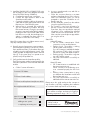
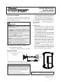
Quick Reference
Install Guide
VSM200/250, DSM200/250
in step 5a of this procedure. The module ID
# is provided on a sticker which can be affixed to the space provided in step 5a.
• Is this a new account or one being added to
an existing account? Check box(es) in 5a.
This information is required for final verification/activation of the VSM200/250 or
DSM200/250.
Installation Procedure
This product is compatible with all Directed Electronics Security, Remote Start and hybrid systems that are
ESP2 compatible (3 or 4-pin).
CAUTIONS
The white plug is ONLY for RSR (Remote Start
Ready) applications
For systems with combined 4-pin ESP/D2D ports,
you CANNOT use an interface module in D2D
mode when using a SmartStart module. You must
use W2W on the bypass module
There should NEVER be more than one data plug
connected from the 3-way harness
DO NOT cut any of the loops on the SmartStart
Module (unless used for RSR applications)
DO NOT connect the black 3-pin ESP connector to
white Door Lock port on Directed systems
Please read the following before proceeding
1. Customer Information required:
• Record the customer information requested
2. Installation Points:
• Install and test the security/remote start system first using the associated guides and
wiring diagram. If using an existing system,
verify it is fully functional before installing the
Directed SmartStart module.
• For 3000-series Remote Start systems with
no supplied remote control, test the installed
system using the functional commands in the
SmartStart activation portal.
• Mount the SmartStart module as high as possible in the vehicle (side with color label and
model number facing down). Mount with
minimal obstructions that can affect communications and within reach of the main Directed system using the provided cables (do
not extend).
• DO NOT connect the SmartStart module until the final programming of the Remote Start
main unit and verification of security/remote
start system operations are completed.
Wiring Schematic
SmartStart Module
(Top view)
Directed System
(Top view)
ESP (4 pin, brn)
4 pin
ESP (3 pin, blk)
LED
2 pin
Fuse
D2D (4 pin, wht)
+12V
GND
NOTE: The appearance and connector/port arrangement on the
Directed/Avital/Xpresskit system may differ to the examples shown .
CPU1
Signal Strength (RSSI)
The module's signal strength (RSSI) can be viewed in the
activation portal after a successful transmission test. This field is
displayed on the webpage as "RSSI: XX dB" with XX being the
numeric variable. Use the range guide (at right) to determine
the signal strength. Monitor this signal during installation to
ensure the device is mounted in a location which maximizes
signal strength with minimal interference.
GPS location accuracy should also be checked on the activation portal when activating DSM/VSM250 modules.
SmartStart
to signal
Xpresskit
-50 to
-90 dB Module
= good
strength
-91 to -100 dB
= borderline/inconsistent signal strength
(see table)
> -100 dB ✂ cut loop
= weak,
insufficient signal strength
4 pin
D2D
QRNDSM250 2011-05
(4 pin, white)
2 pin
+12V
GND
3. Install the VSM200/250 or DSM200/250 using
the information in the wiring diagram and steps
(Note CAUTIONS during installation).
a. Complete the main power connections.
b. Connect the 4-pin extension cable to the
SmartStart module cable.
c. Connect the interface cable to the extension
cable and the other appropriate end into the
Bitwriter port of the Directed system.
d. When power is connected, the module begins an initialization procedure that may
take several minutes. During this procedure,
progress is reported via the flashing Amber/
Green LEDs next to the module cable. When
both LEDs turn on solid, the initialization procedure is completed (See Status LEDs for a
description of the various LED states).
Note: If the system does not include a remote control,
skip step 4 and proceed to step 5.
4. Re-verify security/remote start system operation:
Perform all basic operations such as Lock, Unlock,
Panic and Remote Start, (Trunk release where applicable) using the supplied remote control. If the
system operates as expected proceed to the next
step (5). If the system does not operate as expected, rectify the problem first.
5. Verify and Activate the SmartStart module:
The following steps need to be performed for the
Verification/Activation of the Directed SmartStart
module.
a. Collect Customer Information:
Customer's Full Name:
Customer's E-mail Address:
Customer's mobile phone # and phone carrier
Record/place Module ID # here:
b. Log on to: www.directechs.com, and click on
the SmartStart link.
c. Follow the on-screen directions to activate
and test a SmartStart device. If this is the customer's first SmartStart system, you will be
prompted to enter their information as collected in step 5a.
d. Test the SmartStart system from the website
using the supplied function links.
e. The customer is sent log-in information for
the new Customer Service Portal via e-mail.
From there, they must provide the required
information. Once completed, the installed
system and account are activated. The customer can then open the phone app and begin using the service.
Status LEDs
Amber LED states:
• Off: No cellular communication. Check
connections such as module harness.
• Flashing slowly: The module is seeking
cellular system communication.
If no cell coverage is available the Amber
LED continues to flash slowly, move the
vehicle to a location with better reception.
• Flashing quickly: The module is negotiating with a cellular system.
• On solid: Communication successfully established.
Green LED states:
• Off: Communication not established with
the remote start main unit.
Check connection at the Bitwriter port,
once connected properly the LED turns
on.
• Flashing: Active communication in progress between the SmartStart module and
Remote Start main unit.
• On solid: Communication successfully established with the remote start main unit.
Please return this guide and point the customer to
step 5e after successfully completing the installation
as it contains details required for account setup.
Notes: SmartStart response time can vary depending on cellular coverage and network congestion.
Operating temperature range: -30°C to + 70°C.
Directed Logo Usage
New Account:
Existing Account:
If this is an existing account, are you:
adding a new system:
or replacing an existing one:
Logo, Directed with designed in USA.eps
Additional information
can be found at:
www.directechs.com
Logo, Directed Electronics w-driven.eps
2
© 2011 Directed Electronics. All rights reserved.
Logo, Directed with Distributed By.eps