1
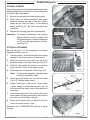
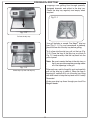
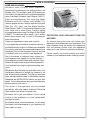
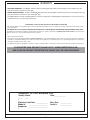
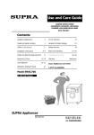
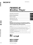
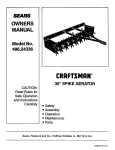
ELECTRIC GRILL
INSTALLATION INSTRUCTIONS
AND OWNER’S MANUAL
Pedestal
model
shown
INSTALLER: Leave these instructions with consumer.
CONSUMER: Retain for future reference.
IMPORTANT: READ THESE INSTRUCTIONS CAREFULLY BEFORE STARTING INSTALLATION OR USE.
SAFETY AND WARNING CODES
•
•
PLEASE READ AND FOLLOW
Removing permanently affixed rating warning
labels WILL void the warranty.
Observe all local codes and ordinances when
installing this appliance. If no local codes are
applicable, wire unit in accordance with the
latest National Electrical Code, ANSI/NFPA 70,
or the Canadian Electrical Code, CSA C22.1,
whichever is applicable.
WARNING
I mproper installation, adjustment,
alteration, service, or maintenance can
cause injury or property damage. For
proper installation, refer to the installation
instructions. For assistance or additional
information, consult a qualified professional
installer or service agency.
WARNING
When connecting this appliance to a power
supply make sure that it is the same voltage as
the unit rating. Improper connection may cause
severe damage to the components or decrease
the performance of your Fire Magic® electric grill.
A rating plate specifying voltage, hertz, wattage,
and amps is attached to the unit and also located
on page 3. To avoid the risk of property damage
and/or personal injury, installation work and
electrical wiring must be performed by a qualified
professional installer. This appliance must be
installed in accordance with this instruction.
WARNING
To minimize the risk of property damage
and/or personal injury, do not use a flexible
extension power-supply cord unless it
conforms with the specifications as listed in
this manual (see page 7 for details).
NOT FOLLOWING THESE
INSTRUCTIONS EXACTLY WILL VOID
THE MANUFACTURER'S WARRANTY.
Certified to: UL 1026-2007
254-B-22-2
Robert H. Peterson Co. • 14724 East Proctor Avenue • City of Industry, CA 91746
REV 3 - 0909231438
1
L-C2-30309
ELECTRIC GRILL
INSTRUCTIONS D'INSTALLATION
ET MANUEL DU PROPRIÉTAIRE
Modèle de
piédestal
montré
INSTALLATEUR : Laissez ces instructions avec le consommateur.
CONSOMMATEUR : Maintenez pour la future référence.
IMPORTANT: LISEZ CES INSTRUCTIONS SOIGNEUSEMENT AVANT DE COMMENCER L'INSTALLATION OU L'UTILISATION.
SÛRETÉ ET CODES D'AVERTISSEMENT
•
•
SVP LISEZ ET SUIVEZ
L'enlèvement de manière permanente a apposé des avertissements d'étiquette d'estimation
videra la garantie.
Observez tous les codes et ordonnances
locaux en installant cet appareil. Si aucun
code local n'est applicable, unité de fil selon
le plus défunt code électrique national, ANSI/
NFPA 70, ou le code électrique canadien, CSA
C22.1, celui qui est applicable.
AVERTISSEMENT
L'installation inexacte, l'ajustement, le
changement, le service, ou l'entretien peuvent
causer des dommages ou des dégats
matériels. Pour l'installation appropriée,
référez-vous aux instructions d'installation.
Pour l'aide ou l'information additionnelle,
consultez un installateur ou une agence
professionnel qualifié de service.
AVERTISSEMENT
En reliant cet appareil à une alimentation d'énergie
assurez-vous que c'est la même tension que
l'estimation d'unité. Le raccordement inexact peut
endommager considérablement les composants
ou diminuer l'exécution de votre gril électrique de
Magic® du feu. Une plaque de contrôle indiquant
la tension, les hertz, la puissance en watts, et
les ampères est attachée à l'unité et également
située à la page 3. Pour éviter le risque de
dégats matériels et/ou de blessures, le travail
d'installation et le câblage électrique doivent
être exécutés par un installateur professionnel
qualifié. Cet appareil doit être installé selon cette
instruction.
AVERTISSEMENT
Pour réduire au minimum le risque de dégats
matériels et/ou de blessures, n'employez
pas une prolongation flexible puissancefournissent la corde à moins qu'elle se
conforme aux caractéristiques comme
énuméré en ce manuel (voir la page 7 pour
des détails).
NON SUIVANT CES INSTRUCTIONS
EXACTEMENT VIDERONT LA
GARANTIE DU FABRICANT.
Certifié à: UL 1026-2007
254-B-22-2
Robert H. Peterson Co. • 14724 East Proctor Avenue • City of Industry, CA 91746
REV 3 - 0909231438
2
L-C2-30309
CONTENTS
PRODUCT DATA TABLE
PARTS LIST
IMPORTANT SAFEGUARDS
INSTALLATION REQUIREMENTS
ENSURING PROPER AIRFLOW
INSTALLATION
COUNTERTOP MODELS
PEDESTAL MODELS
INNER LINERS
CONNECTING TO ELECTRICAL OUTLET
EXTENSION CORDS
OPTIONAL ROTISSERIE
OPERATION
THERMOMETER/THERMOSTAT
COOKING ELEMENT
OPTIONAL ROTISSERIE
DROP DOWN SHELF
FIRE MAGIC® DRIP TRAY
CARE & CLEANING
TROUBLESHOOTING
WARRANTY
3
4
5
6
6
6
6
6
7
7
7
7
8
8
9
9
10
11
12
13
14
PRODUCT DATA TABLE
Specification
Unit height
Unit width
Unit depth
Approximate weight
Value
Pedestal model
Countertop model
43" (lid closed) / 57" (lid open)
14" (lid closed) / 28" (lid open)
25" (shelves down) / 42" shelves up)
19"
20"
20"
76lbs
42lbs
Specification
Value
All models
Electrical requirements
120 volts, 60 hertz, 20 amp; GFI outlet.*
Cook element rating
120 volts 1800 watts 15 amps 60 hertz
* See INSTALLATION section for important details regarding GFI outlets and extension cords.
Table 1 - Product Data Table
REV 3 - 0909231438
3
L-C2-30309
PARTS LIST
Item
Part No.
Description
1.
3549
Cooking grids, 1 pair
2.
23115-01
Element
3.
23115-02
Inner liner kit
4.
23115-26
Handle assy
5.
23115-51
Oven lid assy
6.
3680
Warming rack
7.
23115-12
Digital thermometer
8.
23115-13
Thermometer harness (not shown)
16
6
1
9.
23115-11
Electronic component assy
10.
23115-07
Control panel w/ power cord
11.
23115-14
Meat probe
12.
3086
Drip tray
13.
23115-09
Bumpers, set of 4 *
14.
15.
25115-015 Drop down shelf (2) †
25115-03
Post assy †
16.
3604S
Rotisserie kit ‡
17.
3557
Drip tray liners, set of 4 ‡
(1 sample liner included)
18.
3642
Countertop cover (not shown) ‡
19.
5115-20
Pedestal cover (not shown) ‡
2
3
4
* Countertop models only
5
† Pedestal models only
‡ Optional accessory
9
7
17
13
11
14
10
12
15
Replacement parts can
be ordered from your
local Fire Magic® dealer.
IMPORTANT
Remove all packing
material and discard
prior to use.
Robert H. Peterson Co. • 14724 East Proctor Avenue, • City of Industry, CA 91746
REV 3 - 0909231438
4
L-C2-30309
IMPORTANT SAFEGUARDS
WARNING!
When using electrical appliances, basic safety precautions must always be followed including
the following:
1.
Read all instructions.
2.
Do not touch hot surfaces, always use the handle.
3.
To protect against electrical shock, do not immerse cord, plugs, probe or grill in water or other
liquids.
4.
Close supervision is necessary when any appliance is used near children.
5.
Unplug from outlet when not in use and before cleaning or servicing. Allow to cool before putting
on or taking off parts.
Note: After use and shut-off of this unit, DO NOT immediately disconnect the electric supply.
The electric fan in this unit will continue to operate so that the unit may completely cool.
Always allow sufficient cooling time prior to disconnecting the electric supply.
6.
Do not operate appliance with a damaged cord or plug or after the appliance malfunctions or
has been damaged in any manner. Return appliance to the nearest authorized service facility
for examination, repair or adjustment.
7.
The use of accessory attachments not recommended by the appliance manufacturer may cause
injuries.
8.
Do not let cord hang over edge of table or counter, or touch hot surfaces.
9.
Do not place on or near a hot gas or electric burner or in a heated oven.
10. Extreme caution must be used when moving an appliance containing hot oil or other hot liquids.
11. To disconnect, turn any controls to OFF, then remove plug from wall outlet.
12. Do not use appliance for other than intended use.
13. Fuel, such as charcoal briquettes, is not to be used with appliance.
14. Use only on a properly grounded outlet (see page 7).
15. NEVER grill in the open rain or in standing water as this grill is an electric appliance. There is
always a hazard of electric shock while operating this unit.
16. Keep the appliance area clear and free from combustible materials, gasoline, and other
flammable vapors. WHEN OPERATING THIS UNIT; A MINIMUM 4" CLEARANCE ABOVE
(WITH LID OPEN), AND A 4" CLEARANCE ON ALL SIDES MUST BE MAINTAINED.
17. This appliance does not contain a fuse or surge protector. The power to the unit must be made
readily accessible to the operator through means of a line disconnect switch, circuit breaker,
and/or easy to reach receptacle. For outdoor installation, the circuit must have ground fault
interrupt.
18. Reference the EXTENSION CORD section (page 7) for all specifications.
SAVE THESE INSTRUCTIONS
REV 3 - 0909231438
5
L-C2-30309
INSTALLATION REQUIREMENTS
IMPORTANT: When in operation, this unit must be located with a minimum of 4" clearance above (with
lid open) and 4" clearance on all sides.
ENSURING PROPER AIRFLOW
Proper airflow (Fig. 6-1 and Fig. 6-2) MUST be maintained for the grill to perform as it was designed.
If airflow is blocked, overheating will result. Do not block the 1" (2.5 cm) front air inlet along the bottom
of the control panel or more than 75% of the cooking grid surface with pans or griddles.
CAUTION: DO NOT operate the grill with air blowing into or across the rear oven lid vent (Fig. 6-3).
This can cause poor performance and/or dangerous overheating. Orient the grill so that
any prevailing wind blows against the front of the grill (Fig. 6-1 and Fig. 6-2).
INCORRECT
Place grill so prevailing wind
blows toward front of grill.
Fig. 6-1 - Ventilation
Fig. 6-2
Rear oven
lid vent
Fig. 6-3
You must protect
rear oven vent
from prevailing
wind
WARNING: NEVER cover the entire cooking or grill surface with griddles or pans.
Overheating of the electronic components will occur.
INSTALLATION
COUNTERTOP MODELS
Be sure the unit is stationed on a clean, dry, and level surface, and that all clearance and location
requirements on the previous page are met.
PEDESTAL MODELS
Reference the PARTS LIST on page 4 when installing your pedestal electric grill.
1. Using a Phillips screwdriver, remove the four screws and bumpers on the bottom of the grill. Discard
the bumpers. Align the electric grill onto the top of the post assembly. Using the same four screws,
fasten the electric grill to the post assembly.
2. The post assembly base must be securely fastened to a stable, level surface using the lag screws
and shields provided to ensure the grill remains fixed and upright at all times.
3. Remove the four screws on one side of the grill. Align a shelf assembly to the side of the grill. Using
the same screws, fasten the shelf to the electric grill. Repeat for the other side.
Important: BEFORE USE, the grill base must be securely fastened to a stable, level surface to ensure
the grill remains fixed and upright at all times.
Locate the patio mount base in the planned grill location and mark the 4 holes. Drill the marked holes
to a 1/2" diameter x 1 1/2" depth. Insert the lag shields (see PARTS LIST) into the holes, being sure
that they are flush with the ground.
Align the holes on the patio mount base over the lag shields in the ground. Secure the base with the
lag screws (see PARTS LIST) using a 7/16" nut driver.
REV 3 - 0909231438
6
L-C2-30309
INSTALLATION (cont.)
INNER LINERS
The inner liners come installed in the unit. To
remove for cleaning:
1. Remove the warming rack and cooking grids.
Grasp the cool cooking element and apply
pressure towards the right of the grill. Once it
clears the tab, completely raise it up. Lift the two
side liners up and out (Fig. 7-1).
2. Lift the rear liner slightly up to clear the tab, then
forward and out (Fig. 7-1).
GFI
receptacle
Test and
reset
switches
Grounding
plug
Fig. 7-2
EXTENSION CORDS
Use only a 14-gauge extension cord, with a
3-prong plug, suitable for use with outdoor
appliances. The maximum length allowed for the
extension cord is 25 feet. Do not use damaged
extension cords. Examine extension cord before
using and replace if damaged. Keep cord away
from heat and sharp edges.
3. Move the front liner slightly toward the back of
the grill, then lift up and out (Fig. 7-1).
Re-installing the liners is the reverse of above. (The
order for re-install is front liner, rear liner, then side
liners.)
Important: Connection to an extension
cord shall be kept dry and off the
ground.
OPTIONAL ROTISSERIE
If the optional rotisserie has been selected; the
rotisserie bracket must be installed prior to use.
1. Using a Phillips screwdriver; remove the 2
screws located towards the rear, right side of
the grill.
2. Align the holes of the rotisserie bracket with
the exposed screw holes on the grill. Using the
screws from step 1, fasten the bracket to the
grill (see Fig. 7-3).
Fig. 7-1
Reference the ROTISSERIE section for
instructions on how to use the rotisserie.
CONNECTING TO ELECTRICAL OUTLET
This electrical appliance is equipped with a threepronged (grounding) plug for your protection
against shock hazard and should be plugged
directly into a properly grounded three-prong GFI
protected receptacle. Do not cut or remove the
grounding prong from the plug. (See Fig. 7-2.)
Do not operate any appliance with a damaged
cord or plug, or after an appliance malfunction.
Return the appliance to your dealer or authorized
service facility for inspection, repair or electrical/
mechanical adjustment.
REV 3 - 0909231438
Fig. 7-3
7
L-C2-30309
OPERATION
THERMOMETER/THERMOSTAT
Your electric grill is controlled with a digital thermostat, which includes a built-in timer and alarm with auto shutoff after 2 hours. The thermometer is located on the left side of the control panel. Plug in the meat probe as
shown in Fig. 8-2. The actual grill temperature will be maintained within a 20 degree (Fahrenheit) differential of
the set temperature.
Fig. 8-1
Meat probe
handle
Meat probe
Meat probe
plug
Fig. 8-3
“1” indicates
oven reading
Auto Off
Set temp.
Setting temperature
212˚F
1 104.0˚F
Press
repeatedly
Start
/Stop
Actual temp.
(displays as
dashes when
out of range)
Press
Set
Digit
blinks
Set
Start
/Stop
˚C/˚F
or
Set
ON/OFF
Temp
Timer
“P” indicates
meat probe
reading
Auto Off
Hold
3 sec.
Fig. 8-4
Temp
932˚F
P 212.0˚F
Timer
0:14
Auto Off
Timer
or
Count down
time.
Minutes
Timer
Press once to enter timer mode.
REV 3 - 0909231438
Back to
temp.
display
Displays
time
minutes
flashing
or
Until
desired
numbers
displayed
Until
desired
numbers
displayed
Press
Timer
Displays
time
hours
flashing
Press
Press
Timer
Numbers
stop
flashing
Set
Colon
blinks
countdown
to alarm
starts
Start
/Stop
˚C/˚F
Temp
Temp
Press
repeatedly
Press
repeatedly
Timer Mode
Note: Press any key to silence alarm when beeping.
Alarm will not sound if timer is turned off.
Set
ON/OFF
Return
to temp.
mode
Press
Unit
changes
Hold
3 sec.
Set
Fig. 8-5
Timer is
counting down
when colon is
blinking
Set
Press
Setting and starting the count-down timer
Press once for temp. alternation between probe and oven.
Hours
Until
desired
digit
displayed
Press
Display
shows
C or F
Start
/Stop
˚C/˚F
Temp
Set
Changing temperature units
(Celsius/Fahrenheit)
Set
ON/OFF
Start
/Stop
Set
Press to turn electric grill on or off. Once the grill is turned
on, the cooking element immediately begins to heat. Set
the desired temperature per the diagram to the right.
Displayed when
timer running
Fig. 8-2
Set
Press to enter/exit set time mode.
Press Temp. to return from timer mode.
The internal clicking sound is normal when operating.
8
L-C2-30309
OPERATION (cont.)
COOKING ELEMENT
The cooking element may be adjusted between three
different heights. Be sure the grill is off and completely
cool before any adjustments.
1.
Remove the warming rack and cooking grids.
2.
Grasp the cool cooking element and apply
pressure towards the right of the grill. Once it
clears the tab, raise or lower it to the desired
height. (See Fig. 9-1.) Be sure it securely rests
in position.
3.
Replace the cooking grids and warming rack.
Important: To prevent overheating, the cooking
element must not come in contact with
the thermocouple. A nominal clearance
of 1/8" must be maintained at all times.
(See Fig. 9-2.)
Fig. 9-1
Maintain clearance
at all times
OPTIONAL ROTISSERIE
Fig. 9-2
Be sure the grill is off and completely cool before
beginning rotisserie set up.
1.
Following steps 1 and 2 above, adjust the cooking
element to the lowest position (if necessary).
2.
Slide the rotisserie motor fully onto the motor
bracket located on the right of the grill (Fig. 9-3).
3.
Slide left meat holder into position on rotisserie
rod as shown in Fig. 9-4 and tighten screw.
4.
Slide meat onto rod and into holder (Figs. 9-4).
Fig. 9-3
Note: To allow proper operation, meat diameters
should not exceed 8 inches.
5.
Slide right meat holder onto rod and into meat
(Fig. 9-4). Tighten thumb screw.
6.
Support both ends of the rod so it spins freely.
If meat weight is distributed unevenly, the rod
will rotate until the heavy side of the meat points
downward.
7.
Insert the pointed end of the rod into the motor
drive socket, and the groove next to the knob into
the notch on the left side of the grill.
8.
Plug in the rotisserie motor as shown in Fig. 9-5.
Press the rocker switch to start.
Meat
Right meat
holder
Rotisserie
rod
Left meat
holder
Fig. 9-4
Reference the THERMOMETER section to begin
cooking.
Fig. 9-5
REV 3 - 0909231438
9
L-C2-30309
OPERATION (cont.)
DROP DOWN SHELF
1. To lower the shelf, grab the middle of the
shelf on both sides and lift upward. Then
allow the end of the shelf to rotate down as
pictured to the right.
CAUTION: Do NOT place fingers near hinge
when closing.
Being
lowered or
raised
2. To raise the shelf, grab the middle of the
shelf on both sides and raise it to the
horizontal position. Lift slightly upward, and
lock the shelf safely into position.
Shelf
up & locked
REV 3 - 0909231438
10
Shelf
down
L-C2-30309
FIRE MAGIC® DRIP TRAY
Drippings from grilling flow through specially
designed channels and collect in the drip tray.
Check the drip tray regularly and empty when
required.
Fig. 11-1
Fig. 11-2
Fig. 11-2
Pull out the drip tray
Pull out the drip tray
®
Your
tray
®
Your grill
grill includes
includes aa sample
pack of Fire
four Magic
(4) Fire drip
Magic
liner
11-1).(Fig.
For your
convenience
in cleanup,
drip (Fig.
tray liners
11-1).
For your convenience
place
the
liner
into
the
drip
tray
before
grilling.
in cleanup, place a liner into the drip tray before
grilling.
To
fit a liner into the drip tray, pull out the tray (Fig.
11-2).
the the
linerdrip
in the
as tray
shown
in
To fit aPlace
liner into
tray,drip
pull tray
out the
(Fig.
Fig.
11-3
and
carefully
slide
the
tray
back
into
the
11-2) and set it on a flat, level surface (Fig. 11-3).
control
panel.
Place the
liner in the drip tray as shown in Fig. 11-4
Fig. 11-3
Remove a drip tray liner from the package
and carefully
the tray
the control
Note:
Be sureinsert
to center
theback
liner under
in the drip
tray, so
panel (Fig.
11-5).
that it may provide complete coverage under
all ofuse,
thewait
openings
the
After each
for the in
grill
to grill.
cool and carefully
Fig. 11-3
pull out
the
drip
tray
check
When
liner is
After
each
use,
wait
fortothe
grill toit.cool
andacarefully
nearing
full,
carefully
lift
it
out
of
the
drip
tray,
pull out the drip tray to check it. When the liner
is
lifting
with
both
hands
to
keep
the
tray
level
until
nearing full, carefully lift it out of the drip tray, lifting
it is both
safely
discarded.
insert
a until
newitdrip
tray
with
hands
to keepThen
the tray
level
is safely
liner.
discarded.
Center drip tray liner into drip tray
Order more
more drip
drip tray
tray liners
Order
liners through
through your
your local
local Fire
Fire
®
®
Magic
dealer.
Magic dealer.
Fig. 11-4
Place the drip tray liner
Note: The foil tray liner is also useful for setting
on burners to cover them and catch
drippings directly during rotisserie only
cooking.
Note: For models with match holders attached
inside the drip tray, place the match
holder off to one edge of the pan (Fig.
11-3). If necessary, mold the foil liner
around them and the other features of the
tray to create enough clearance space to
open and close the tray without catching
the liner.
Fig. 11-5
Carefully slide the tray with liner back into the opening
11
CARE & CLEANING
CARE AND CLEANING
Stainless steel surfaces when exposed to
temperatures produced by the grilling process will
change color. The stainless steel will change color
from silver to brown and blue. This can be removed by
using Fire Magic Stainless Steel Cleaner (3581-1).
e
Wip
n
grai
h
t
i
w
Clean your appliance by fi rst using Fire Magic
Barbecue and Grill Cleaner (part #3580-1) to
remove grease and dirt. Always wipe with the grain
(See Fig. 12-1). Next, use Fire Magic Stainless
Fig. 12-1 - Wipe with grain
Steel Cleaner (3581-1) to restore the stainless steel
color (Note: not for mirror finish). Finish by wiping
your appliance down using Fire Magic Polish Wipes
(3586-1). To clean the mirror panel, use a quality
PROTECTING YOUR APPLIANCE FROM THE
brand glass cleaner only, not any of the cleaners
WEATHER
mentioned above.
An optional heavy-duty cover will protect your
Clean your appliance at least once a month.
appliance’s finish and protect your investment. The
If your appliance is installed in a seaside (salt air) or water repellent cover will protect your appliance
poolside (chlorine) location, it will be more susceptible from the weather. Always cover your appliance
to corrosion and must be maintained/cleaned more when not in use. (Allow to cool before covering.)
frequently. Do not store chemicals (such as chlorine
Please specify the model number and serial
or fertilizer) near your stainless steel appliance.
number of your appliance when ordering a cover.
Due to the nature of stainless steel, surface iron
oxide deposits may appear. Do not be alarmed –
these deposits are removable with stainless-steel
cleaner through prompt and periodic maintenance.
If not attended to promptly, permanent pitting may
occur.
Check and clean
ports
burner
Periodically
clean the
the burner
drip tray
andand
inner
linerscarryof all
over slits for blockage
annually
by removing
food/grease
deposits at
to least
reduce
the chance
of fire
the burner
(see orifi
ce changing
instructions)
and
and
assure proper
operation.
The drip
tray and inner
visually
burner
for insects
and
liners
areinspecting
removablethe
for hand
or inlet
dishwasher
cleaning.
nests. A clogged
burner can section
lead to for
a fiinner
re in liner
the
Reference
the INSTALLATION
bottom The
of the
appliance.
(For
Fire
use
details.
cooking
element
does
notMagic
need grills
cleaning.
Maintenance Kit part #MK-1.)
The inside of the appliance may be cleaned
periodically with oven cleaner if desired. Follow the
oven cleaner instructions for proper use.
Be careful not to get oven cleaner on the outside
surface of the appliance as it can permanently
damage the finish.
By following these recommendations, you will enjoy
the beauty and convenience of your appliance for
many years to come.
12
TROUBLESHOOTING
Magic®
If you have trouble with this Fire
grill, please use this list to identify the problem. By trying one or more of the
solutions to the possible cause, you should be able to solve the problem. If this list does not cover your present problem,
or if you have other technical difficulties with the grill, please contact your local Fire Magic® dealer or visit our web site at
www.rhpeterson.com.
PROBLEM
Ignition system
Grill does
not work
failure
Thermometer does
not work
Insufficient heat
Cooking element
does not work
Uneven heating
Thermometer
malfunction
Rotisserie noisy
POSSIBLE CAUSE
CORRECTION
1. Power not hooked to power supply
1. Power failure
2. Improper air shutter adjustment
2. Power not plugged correctly
3. Ignition wire disconnected
4.
gas pressure
3. Low
GFI plug
may be tripped
5. Front carry-over port
1. Replace ignitor battery.
1. Check if power is available.
2. Adjust air shutters.
2. Make sure the power cord plug is properly
3. Plug wires back into ignition switches.
inserted into the receptacle.
4. Have the gas co. check supply pressure.
3. Reset switches on the GFI receptacle.
5. Clean burner ports
6. Improper air-shutter adjustment
1. No power to unit
7. Using propane orifice for natural gas
2. Faulty component
8. Low gas pressure/flame (propane)
6. Adjust air shutters.
1. Assure power is available.
7. Check/change orifices.
2. Contact your dealer.
8. Shut off all valves, including propane tank,
and follow lighting instructions exactly.
(See important note* below.)
1. No power to unit
1. Assure power is available.
9. Low gas pressure/flame (natural)
9. Have the gas co. check pressure at grill.
2. Bad element
2. Contact your dealer.
10. Burner ports partially blocked by 10. Remove burners and clean out ports.
debris
11. Inspect burners and orifices for spider webs
Table 2
or other debris that may block flow.
11. Small spiders or insects in burner
12. Adjust air shutter.
12. Improper air shutter adjustment
13. Battery charge low
13. Replace batteries. Check connections to
batteries.
14. Rotisserie out of balance
14. Adjust rotisserie counterbalance.
15. Light burner on HIGH, immediately turn to
LOW setting. Remove knob from valve and
using a small flat screwdriver, slowly turn
Burner goes out on
the adjustment screw in the stem, a little at
15.
Valve
“Low”
setting
needs
adjustment
LOW
a time (30° to 45°), in either direction, until
the flame is approximately 1/4” in height
from burner ports.
Table 2
13
WARRANTY
TEN-YEAR WARRANTY - Fire Magic® stainless-steel rod cooking grids and stainless-steel housings are warranted for ten (10)
years from the date of purchase of your grill.
THREE-YEAR WARRANTY - All other Fire Magic® grill components (except ignition and electronic parts) are warranted for three (3)
years from the date of purchase of your Fire Magic® grill.
Fire Magic® ignition systems (excluding batteries), electronic components (including lights and thermometers), and accessories are
warranted for one (1) year from date of purchase.
PLEASE KEEP A COPY OF YOUR SALES SLIP FOR PROOF OF PURCHASE
This warranty applies to the original purchaser and to single family residential use only. It commences from date of purchase, and is valid only with
proof of purchase.
This warranty does not cover parts becoming defective through misuse, accidental damage, electrical damage, improper handling, storage, and/or
(and
gas ed
must
be connected)
ed inmanual,
the instructions
or operator’s
manual,installer.
by a qualifi
ed professional
installation. Product must be installed as
specifi
in the
instructionsas
or specifi
operator’s
by a qualifi
ed professional
Accessories,
parts,
installer.
Accessories,
parts,
valves,
etc., when
used must be Peterson Co. product.
valves,
remotes,
etc., when
used
mustremotes,
be Peterson
Co. product.
This warranty does not apply to rust, corrosion, oxidation, or discoloration, unless the affected component becomes inoperable. It does not cover
labor or labor-related charges.
This warranty specifically excludes liability for indirect, incidental, or consequential damages. Some states do not allow the exclusion or limitation of
incidental or consequential damages, so the above exclusion may not apply to you. This warranty gives you specified legal rights, and you may have
other rights that may vary from state to state.
For additional information regarding this warranty, or to place a warranty claim, contact the R.H. Peterson dealer where the product was purchased.
TO REGISTER YOUR PRODUCT ONLINE GO TO: WWW.RHPETERSON.COM,
AND CLICK ON PRODUCT REGISTRATION. THANK YOU FOR YOUR PURCHASE.
ROBERT H. PETERSON CO.
Quality Check
Date:___________
Orifice # (Main):__________
Orifice # (Other):__________
Electrical
Leak Test: ___________
Leak Test:
___________
Model
#:
___________________
Burn Test: ___________________
___________
Inspector:
Gas Type:
NAT. / PROPANE
Model
#:
___________
Burn Test:
Serial #:
___________
Air Shutter: ___________
Inspector: ___________
Robert H. Peterson Co. • 14724 East Proctor Avenue • City of Industry, CA 91746
14