1
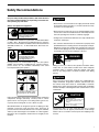
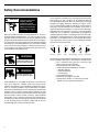
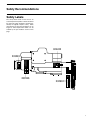
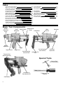
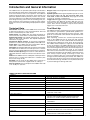
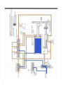
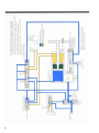
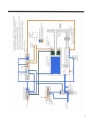
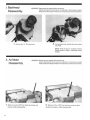
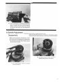
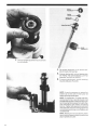
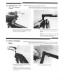
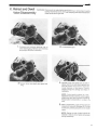
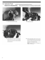
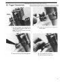
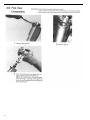
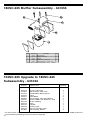
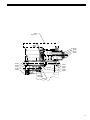
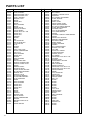
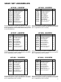
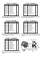
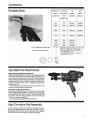
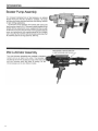
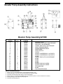
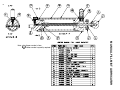
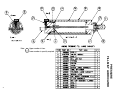
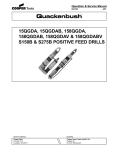
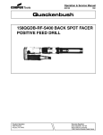
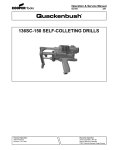
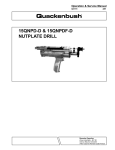
Parts Manual
823225
06/03/2013
180SC-225 Drill
Self Colleting
For additional product information visit our website at www.apextoolgroup.com
2
Safety Recommendations
For your safety and the safety of others, read and understand
the safety recommendations and operating instructions before operating any drill motor.
Always wear protective equipment:
!
WARNING
Impact resistant eye protection
must be worn while operating
or working near this tool.
For additional information on eye protection, read the latest edition
of ANSI Z87.1, Occupational and Educational Eye and Face
Protection. This standard is available from the American National
Standards Institute, Inc., 11 West 42nd Street, New York, N.Y.
10036.
!
CAUTION
!
CAUTION
• Before the tool is connected to the air supply, the throttle should
be checked for proper operation (i.e., throttle valve moves freely
and returns to closed position).
• Before removing a tool from service or changing drill bits, make
sure the air line is shut off and drained of air. This will prevent the
tool from operating if the throttle is accidently engaged.
• Cutting tools used with these drill motors are sharp. Handle them
carefully to avoid injury.
• The collet and mandrel must be inserted into a properly sized
pre-drilled hole before starting the tool. An improperly sized predrilled hole prevents the mandrel from engaging the collet and
could result in slippage of the tool. An improperly selected collet
and mandrel can also result in slippage of the tool.
!
Personal hearing protection is
recommended when operating
or working near this tool.
Hearing protection is recommended in high noise areas (above
85dBA). Close proximity of additional tools, reflective surfaces,
process noises, etc., can contribute substantially to the sound
level experienced by the operator.
!
WARNING
WARNING
Wear respirator where
necessary.
Drilling or other use of this tool may produce hazardous fumes
and/or dust. To avoid adverse health effects utilize adequate
ventilation and/or a respirator. Read the material safety data
sheet of any cutting fluids or materials involved in the drilling
process.
!
CAUTION
Some non-ferrous metal chips (or dusts) are combustible. Examples: Aluminum, magnesium, Titanium, and Zirconium. See
the material safety data sheets for combustibility of materials
drilled. Never collect spark generating material with combustible
material. Examples: Collecting both steel and aluminum or steel
and titanium.
Do not wear loose fitting clothes,
long hair, gloves, ties or jewelry.
!
Follow good machine shop practices. Rotating shafts and moving
components entangle and entrap, and may result in serious
injuries. Never wear long hair, loose-fitting clothes, gloves, ties,
or jewelry when working with or near a drill of any type.
Quackenbush drills are designed to operate on 90psig (6.2 bar)
maximum air pressure using the proper hose. Excessive air
pressure increases the loads and stresses on tool parts and drills,
and may result in breakage. The installation of a filter-regulatorlubricator in the air supply line ahead of the tool is highly recommended.
CAUTION
Slip and fall hazard.
Lubricant and coolant systems must
be properly maintained to avoid
leakage.
Hoses must be organized and care
taken to avoid tripping.
Quackenbush drills are often used with lubricant or cooling
systems which must be properly maintained to avoid leakage.
Failure to do so can result in serious injuries from slipping on oily
surfaces.
3
Safety Recommendations
!
WARNING
Keep hands away from
clamping and feed
mechanisms. Clamp
mechanism moves when
drilling and connecting
or removing air supply.
Due to the number and variety of tooling applications, the user's
methods engineering departments, ect., must consider any hazards that may be associated with each specific application of this
product and provide adequate operator protection from inadvertent contact with any moving components. The clamping and feed
mechanisms of self-colleting drill motors are exposed for visibility
and can move when the air supply is connected or disconnected.
To avoid injury, keep fingers and hands away from these areas
when handling or operating this tool.
Any tool operator should be aware of the following warning signs
and symptoms so that a problem can be addressed before it
becomes a debilitating injury. Any user suffering from prolonged
symptoms of tingling, numbness, blanching of fingers, clumsiness or weakened grip, inability to hold objects, nocturnal pain in
the hand, or any other disorder of the shoulders, arms, wrists, or
fingers should notify their employer so that a review of what steps
might be taken to prevent further occurances. These steps might
include but are not limited to, repositioning the workpiece or
redesigning the workstation, reassigning tool users to other jobs,
rotating jobs, changing worker pace, and/or changing the type of
tool used so as to minimize stress on the operator. Some tasks
may require more than one type of tool to obtain the optimum
operator/ tool/ task relationship.
Avoid
Extension
!
WARNING
Repetitive work motions can
injure your hands and arms.
!
WARNING
Exposure to vibration can
injure your hands and arms.
Some individuals are susceptible to disorders of the hands and
arms when exposed to vibration and/or tasks which involve
repetitive work motions. Those individuals predisposed to vasculatory or circulatory problems may be particularly susceptible.
Cumulative trauma disorders such as carpal tunnel syndrome and
tendinitis can be caused or aggravated by repetitious, forceful
exertions of the hands and arms. These disorders develop gradually over periods of weeks, months, and years. Tasks should be
performed in such a manner that the wrists are maintained in a
neutral position, which is not flexed, hyperextended, or turned side
to side. Stressful postures should be avoided and can be controlled through tool selection and work location.
4
OK
Neutral
Avoid
Flexion
Avoid
Radial Deviation
OK
Avoid
Neutral
Ulnar Deviation
The following recommendations will help reduce or moderate the
effects of repetitive work motions. The operator of any drill should:
• Use a minimum hand grip force consistent with
proper control and safe operation
• Keep body and hands warm and dry
• Avoid anything that inhibits blood circulation
— Smoking Tobacco
— Cold Temperatures
— Certain Drugs
• Avoid awkward postures
• Keep wrists as straight as possible
• Interrupt work, activities, or rotate jobs to provide
periods free from repetitive work motions.
Safety Recommendations
Safety Labels
The safety labels found on this tool are an
essential part of this product. Labels should not
be removed. Labels should be checked periodically for legibility. Replace safety labels
when missing or when the information can no
longer be read. Replacement labels can be
ordered by the part numbers shown on this
page.
624242
203245
-
!
! WARNING
624242
!
WARNING
Keep hands away from this area when handling
or operating tool. Clamp mechanism moves when
drilling and connecting or removing air supply.
202902
203246
Keep hands away
from clamping and
feed mechanisms.
Clamp mechanism
moves when drilling
and connecting or
removing air supply.
WARNING
CAUTION
Read operating
instructions before
operating tool.
!
Wear impact resistant eye protection.
Hearing protection is recommended.
Avoid contact with rotating spindle or cutter.
Wear respirator as necessary.
Exposure to repetitive work motion
and/or vibration may be harmful
203246
to your hands and arms.
OPERATING
INSTRUCTIONS
203245
202902
5
Index
Safety Recommendations
Major Tool Components
Introduction and General Information
Air System Diagrams
Backhead Disassembly
Air Motor Disassembly
Spindle Adjustment
Quill & Pressure Foot Removal
How to Change Quills
Feed Clamp Disassembly
Dwell Valve Disassembly
Disassembly of Feed Control Plug
Unclamp Check Valve Disassembly
Retract and Dwell Valve Disassembly
Hydraulic Fluid Reservoir Disassembly
Trigger Disassembly
Pilot Valve Disassembly
3-5
6
7
8-11
12
12-13
13-14
15
15-16
16-18
19
19
20
21
22
23
24
Tool Adjustments
Drill Assembly
Gear Set Assemblies
25
26-30
31-32
Accessories
Template Boss
Jig Collet Foot Attachments
High Curvature Pad Assembly
Booster Pump Assembly
Mist Lubricators
Trouble Shooting & Maintenance Kit
33
33
33
34-35
34-38
39
Major Tool Components
Spindle
Adjustment
Clamp
Dwell
Depth Control
Adjustment
Nut
Depth Control
Clamp
Feed Sleeve
Motor
Exhaust
Backhead
Spindle
Adjustment
Trigger
Bypass Cover
Air Inlet Bushing
(3/8-18 FNPT)
Trigger Lock
Variable Spacing
Pressure Foot
Template Boss
(See Accessories)
Feed Rate
Adjustment
Adjustable Tail
Pad
Special Tools
Pressure Foot
Nut Tool (623014)
Accessory Air
Port (250-18 NPT)
Collet Guide
6
Trigger Lock Tool
(623015)
Introduction and General Information
The 180SC-225 is air operated, hydraulically controlled tool
that automatically clamps to the material, drills and countersinks close tolerance holes in one operation. The 180S will
produce high quality holes in aluminum, steel, titanium and
petroleum hybrid materials primarily found in the aircraft/
aerospace industries. The 180S self-colleting drill motor has
been designed using state-of-the-art technology that provides maximum power,minimum weight and the highest
degree of accuracy for demanding hole preparation requirements.
Technical Data
Feed Stroke: Feed stroke of the 180SC-225 is 2.25 inches
to drill and countersink in 2 inch stacked material. The feed
stroke is unaffected by the collet stroke.
Collet Stroke: The 180SC-225 will clamp throughout its
.875 inch stroke. Feed stroke is unaffected by collet stroke.
Spindle Adjustment: The spindle adjustment of .375 inch
allows for drill length variations. See Spindle Adjustment
information on page 25.
Countersink Depth Control: A micrometer adjustment
provides for countersink stop repeatability within .001 inch.
Cutter Sizes: The 180SC-225 will accommodate .500 diameter drills and.875 countersink diameter.
Feed Rate: An adjustable drill feed rate mechanism enables
the 180SC-225 to drill from 5 seconds per inch to 1 minute
per inch. See Feed Rate Adjustment information on page 25.
Cutter to Collet Spacing: The cutter to collet distance is
adjustable between 1.00 inch minimum to 3.50 inch maximum.
Coolant: The 180SC-225 has a drill point coolant port in the
pressure foot. A coolant mist lubricator is available (See
Accessories Page 32-38)
Air Motor: The air motor for the 180SC-225 is rated at 1.8
horsepower nominal when supplied with air at 90 p.s.i.
Air Consumption: Air consumption of the 180SC-225 is 68
c.f.m. at 90 p.s.i. dynamic.
Weight: 180SC-225 weight with the aluminum pressure foot
is 14.9 pounds.
Spindle Speeds: Eleven geared spindle speeds are available with the 180S: 240, 420, 650, 850,1050, 2000, 3100,
4900, 6300, 12500 and 21000 RPM. See pages 31 and 32
for gear set assembly configurations.
Trigger Lock: A trigger lock is provided which allows the tool
to be locked in the "Operate" position. With the lock activated, the tool will run through the clamp, feed and retract
cycles, but it will not unclamp or stop the motor until the
trigger lock is manually released.
Tool Start-Up
The 180SC-225 drill is shipped from the factory equipped to
the customer's specifications: spindle RPM, spindle to accommodate cutter type desired, pressure foot type, collet
guide to accommodate collet desired and optional booster
pump (if required).
After unpacking, examine the customer-specified equipment on the 180SC-225 tool to verify type and speed of
components. Attach air line to 3/8-18 NPT inlet bushing. If
quick disconnect fittings are used, 3/8 in. ID are minimum.
The 180SC-225 drill requires a supply of clean 90-100 PSI
air. Air consumption is 45 CFM at 90 PSI. The use of the inline lubricator will provide the proper lubrication for the air
motor and will significantly increase the tool life expectancy.
Because O-rings are extensively used to seal systems
within the tool, the elimination of foreign particles and other
contaminants will reduce the possibility of damage to these
parts. Always inspect O-rings for damage or wear and
replace as required. The use of silicone O-ring lubricant is
strongly recommended during reassembly. The addition of
oil in the air line will also increase motor and valve life as well
as the life of the O-rings. Avoid the use of synthetic lubricants
to prevent damage to O-rings and seals.
180SC-225 DRILL SPECIFICIATIONS
WEIGHT
180SC-225-14.0 LBS. MAX. W/ALUMINUM FOOT
AIR CONSUMPTION
68 C.F.M. @ 90 P.S.I. DYNAMIC
HORSE POWER
APPROX. 180S-1.4 @ 90 P.S.I.
O/A LENGTH
180S-15.28 IN. MAX AT FULL EXTENSION
STROKE
2.225 IN. (DRILL & C/SINK 2 IN. STACK)
COLLET STROKE
.875 IN. (NO LOSS OF FEED STROKE)
COUNTERSINK
COUNTERSINK STOP REPEATS WITHIN .001 IN.
FEED RATE
MIN. 5 SEC. PER INCH, MAX 1 MIN. PER INCH
SPINDLE SPEEDS
240, 420, 650, 850, 1050, 2000, 3100,
4900, 6300, 12500, 21000
DRILLING THRUST
300 LBS. MAX. (WITHOUT BOOSTER PUMP)
CLAMP FORCE
548 LBS. START CLAMP STROKE (UNREGULATED AIR)
460 LBS. FULL CLAMP STROKE (UNREGULATED AIR)
SPINDLE ADJUSTMENT
.375 IN. ADJUSTMENT TO ALLOW FOR DRILL LENGTH
VARIATIONS
MAX. DRILL SIZES
.500 DRILL/.875C/SINK
COLLET FOOT SPACING
1.00 IN. MIN. - 3.50 IN. MAX.
SPINDLE
.500 IN. DIA. W1/4-28 & 3/8-16 O.D. THD OR 1/4-28 I.D. THD
THREAD TYPE DRILLS OR 1/4-28 TAPER-LOK TYPE DRILLS.
COOLANT
AIR BLAST PORT & DRILL POINT PORT IN TEMPLATE STD.,
COOLANT MIST LUBRICATOR AVAILABLE.
7
8
9
10
11
12
13
14
15
16
17
18
19
20
21
22
23
24
Tool Adjustments
WARNING: Disconnect air-supply before servicing.
Clamp mechanism moves when connecting or removing air supply.
Keep hands and fingers away from clamping and feed mechanism.
Spindle Stroke Adjustment
Dwell Adjustment
Loosen spindle adjustment lock, then turn spindle adjustment knob. Right hand rotation advances cutter foward;
left hand rotation returns cutter. Correct cutter point
position is flush with face of template boss. When cutter
is properly adjusted, lightly tighten spindle adjustment
lock to hold adjustment.
Insert appropriate size allen wrench into dwell adjustment
valve opening. Rotate wrench clockwise until valve seats
lightly. Rotate valve counterclockwise 1/2 turn to obtain
base setting.
Note: If adjustment valve is opened too far, drill motor will
not cycle, and feed cycle cannot be obtained. To correct,
turn valve clockwise to seat valve and set according to
instructions above.
Micrometer Depth Adjustment
Loosen adjustment clamp, and rotate depth adjustment
nut. Clockwise rotation decreases depth; counterclockwise increases depth. Graduations scribed on barrel are
in .001" increments. When proper depth is achieved.
lightly tighten adjustment clamp.
Feed Rate Adjustment
With appropriate tool, turning feed rate adjustment counterclockwise, increase feed rate. Turning the screw clockwise decreases feed rate. Feed rate can be measured by
using the following formula:
60 seconds
Time to drill one inch = -----------------------------------------Feed Rate x Spindle Speed (rpm)
If valve is closed too far, retract cycle cannot be obtained.
To correct, turn valve counterclockwise and set according to instructions.
Closing valve increases countersink dwell time; opening
valve decreases countersink dwell time.
Tail Pad Adjustment
The purpose of the tail pad is to compensate for slght
surface curvature of the workpiece being drilling and to
assure that the hole being drilled is perpendicular to the
surface.
To adjust to a flat plane for drilling flat surfaces, use a
straight edge between the tail pad and face of template
boss and adjust the tail pad until the straight edge is flush
with the face of the template boss.
An optional tail pad is available for high curvature surfaces. ( See Accessories for more information.)
25
180SC-225 Muffler Subassembly - 641055
5
2
4
2
3
1
2
5
1
1
ITEM
1
PART NO.
632130
PART NAME
BOX, MUFFLER
QTY.
1
2
632126
ELEMENT, MUFFLER
5
3
4
632132
619995
PLENUM
SCREW, SHC (10-24UNC-3A)
1
2
5**
632125
SCREW, HSBHC (10-32UNF X 1.250)
2
** PARTS NOT INCLUDED IN SUBASSEMBLY: 632125 - SCREWS
153SC-225 Upgrade to 180SC-225
Subassembly - 641052
Part No.
Name of Part
622279
622329
622758
624973
625577
629556
632125
632128
632129
632131
632133
632178
641055
Spacer, Pilot Valve
Subassembly, Pilot Valve
Updated Rear Bearing Plate
Fitting
Rotor Blade
Subassembly, Gear Plate Spacer
Screw, HSBHC (10-32UNF X 1.250)
Screw, Indexing
Rotor
Cylinder
Bushing, Inlet
Valve, In-line Non return
Subassembly, Muffler
Quantity
1
1
1
1
4
1
2
1
1
1
1
1
1
On some earlier models the 622758 Updated Rear Bearing Plate with the slot that has been added to allow the
use of the 632128 Indexing Screw must be also replaced.
26
622860
622861
624016
844305
844310
625650
625648
624020
622773
624021
SPINDLE SET
619164
622778
622777
624018
632125
641055
Muffler Assy.
867745
622776
622774
624019
SPINDLE GEAR SHOWN ONLY
SEE SPECIFIC GEAR ASSEMBLIES
FOR ASSEMBLY INSTRUCTIONS
625580
625772
623848
622695
864737
622134
843791
ASSEMBLE
622700 BACK-TO-BACK
622780
622779
622698
623875
615018
844305
812963
622387
622697
622778
624024
622690
625647
625652
625649
625651
622354
622256
622688
621520
622833
624032
624035
COLLET AND MANDREL SHOWN BUT
NOT SUPPLIED WITH THIS ASS'Y
.3073-.4114 DIA.-
622252
622253
.4166-.4740 DIA.-
622254
.1560-.3021 DIA.-
812231
624036
625085
625498
622769
844407
622777
PRESSUE FOOT - RIGHT HAND
PRESSUE FOOT - LEFT HAND
622088
844301
622770
622054
622073
623691
864271
844306
844312
624030
863009
619656
622280
622329
623084
622279
632133
- ASSEMBLY,GEAR SET
621835
621503
621837
240 RPM
420 RPM
650 RPM
621836
850 RPM
621504
621606
1050 RPM
2000 RPM
621505
621686
621506
621507
621537
3100 RPM
4900 RPM
6300 RPM
12500 RPM
21000 RPM
- USE LOCTITE ON TH'DS
27
(2 REQ'D)
845614
623641
A
B
C
622056
(3 REQ'D)
632128
812962
622255
622358
With Lubricator 624973
625078
B
622617
622616
622618
622615
C
622053
(3 REQ'D)
622768
847710
(3 REQ'D)
843434
A
847710
(2 REQ'D)
844303
(2 REQ'D)
623596
623880
623881
812568
(4 REQ'D)
847710
(2 REQ'D)
622250
612625
622384
28
641055
Muffler Assy.
847095
864335
615641
622759
847095
632129
619017
863454
622765
847272
624028
843434
625577
632131
624027
622642
622970
615645
844265
843518
844892
29
PARTS LIST
Part No.
203245
203246
624032
624035
624242
612625
615018
615641
615645
619017
619164
619656
621620
622026
622053
622054
622056
622073
622088
622134
622250
622255
622256
622277
622279
622280
622329
622353
622358
622376
622384
622387
622615
622616
622617
622618
622620
622642
622688
622695
622697
622698
622700
622757
622758
622759
622765
622768
622769
622770
622773
622774
622775
622776
622777
622778
622779
622780
622833
622860
622861
622862
622970
623084
30
Name of Part
LABEL; CAUTION
LABEL; WARNING
PRESSURE FOOT; RIGHT
PRESSURE FOOT; LEFT
LABEL; WARNING
WASHER; PLAIN
O-RING
SCREW; BHC
O-RING
RING; RETAINING
O-RING
SCREW; SFCHC
SUBASSY; BUSHING
VALVE; NEEDLE
SCREW, BHC 6-32 X .500
SCREW; SET
SCREW; SHC
TRIGGER
SPRING
KEY
PAD; PRESSURE
COLLET GUIDE CLIP
LIFT LEVER PIN
PLUG
SPACER
PISTON
ASSY; PILOT VALVE
SPRING; COMPRESSION
PIPE; PLUG
RING; RETAINING
SCREW; SHC
SPACER
RING; RETAINING
SPRING
PIN; TRIGGER LOCK
BUSHING; TRIGGER LOCK
SUBASSY; CHECK VALVE
SCREW
HOLDER; COLLET
BULKHEAD; REAR
PISTON; CLAMP-UNCLAMP
NUT; BEARING RETAINING
BEARING; BALL
SUBASSY; VALVE
PLATE; REAR BEARING
PLATE; FRONT BEARING
PLUG; RESERVOIR
COVER
RING; RETAINING
RING; RETAINING
SCREW; SHC
SCREW; SHC
SCREW; BHC
O-RING
O-RING
O-RING
LOCKNUT
WASHER; LOCK
COLLET SPRING
SPRING; COMPRESSION
WASHER
NON-REGULATING PLUG
O-RING
SCREW; ORIFICE
Qty. Part No.
1
1
1
1
1
1
2
1
14
1
1
1
1
1
3
1
3
1
1
1
1
1
1
2
1
1
1
2
1
2
1
1
1
1
1
1
1
1
1
1
1
1
2
1
1
1
1
1
1
2
1
3
3
1
2
2
1
1
1
1
1
1
2
1
623596
623641
623691
623848
623875
623880
623881
624016
624018
624019
624020
624021
624024
624027
624028
624030
624036
624121
625078
625085
625498
625577
625580
625581
625645
625647
625648
625649
625650
625651
625652
632125
632131
632133
641055
812164
812231
812568
812962
812963
832128
832129
843434
843518
843791
843913
844265
844301
844303
844305
844306
844310
844312
844892
845614
847095
847272
847665
847710
863009
863454
864271
864335
864737
867745
Name of Part
SCREW; SHC
NUT; ACORN
ASSEMBLY; TRIGGER VALVE
BACKHEAD
NUT; SPINDLE ADJUSTMENT
CLAMP; BUSHING
CLAMP; NUT
SHAFT; CLAMP
CHECK PISTON; CLAMP
COVER; DEPTH CONTROL
NUT ADJUST; DEPTH CONTROL
CLAMP; DEPTH CONTROL
CYLINDER; LINER
PLUG; FLUID RESERVOIR
PLUG; FEED CONTROL
HANDLE
CYLINDER; HYDRAULIC FEED CONTROL
GASKET
SCREW; FLAT HEAD CAP
BRACKET; FEED CONTROL
BULKHEAD; FRONT
BLADE; ROTOR
SPACER; BACKHEAD
SPINDLE
NUT; PRESSURE FOOT
BUSHING; PULL ROD
PULL ROD
CLEVIS PIN; LINKAGE
CLAMP-FEED SHAFT
LINKAGE; CLEVIS
LIFT FINGER
SCREW; BHC 10-32 UNF X 1.250
CYLINDER
BUSHING; INLET
SUBASSEMBLY; MUFFLER
PIN; SPRING
RING; RETAINING
SCREW; ALLEN CAP
SCREW; BHC 10-32 UNF X .250
SCREW; BHC 10-32 UNF X .500
SCREW; INDEXING
ROTOR
PLUG; PRESSURE
SCREW; SET
RING; RETAINING
COLLAR; ROTOR
BALL (1/8)
O-RING
O-RING
O-RING
O-RING
O-RING
O-RING
PLUG; PIPE
SCREW; SFCHC
BEARING; BALL
O-RING
RING; RETAINING
O-RING
O-RING
O-RING
SNAP RING
BEARING CAP
O-RING
O-RING
Qty.
1
1
1
1
1
1
1
1
1
1
1
1
1
1
1
1
1
1
3
1
1
5
1
1
1
1
1
1
1
1
1
2
1
1
1
1
1
4
1
1
1
1
2
1
2
1
1
2
1
2
2
1
4
1
2
2
2
1
7
1
1
1
1
1
1
GEAR SET ASSEMBLIES
621503 - 420RPM
621835 - 240RPM
Part No.
623848
REF.
621515
623772
623770
623769
623771
622129
812231
622134
833689
622787
629556
Name of Part
Assembly, Backhead
Assembly, Spacer
Plate, Gear Set
Gear, Spindle
Pinion, Reduction
Gear, Reduction
Bearing, Ball, Flng
Ring, Retaining
Key, Woodruff
Ring, Retainer
Screw, Soc, Hd, Cap
Gear Plate Spacer
Qty.
1
1
2
1
1
1
2
1
1
2
4
1
Part No.
623848
REF.
621515
622803
622800
622801
622802
622129
812231
622134
622787
629556
Name of Part
Assembly, Backhead
Assembly, Spacer
Plate, Gear Set
Gear, Spindle
Pinion, Reduction
Gear, Reduction
Bearing, Ball, Flng
Ring, Retaining
Key, Woodruff
Screw, Soc, Hd, Cap
Gear Plate Spacer
Qty.
1
1
2
1
1
1
2
3
1
4
1
Backhead Assembly is shown for reference only and is
not part of the gear assembly. Spindle Gear is not shown,
but is supplied loose with assembly. Retainer Ring is used
on the 180 RPM only.
Backhead Assembly is shown for reference only and is
not part of the gear assembly. Spindle Gear is not shown,
but is supplied loose with assembly.
621837 - 650RPM
621836 - 850RPM
Part No.
623848
REF.
621515
623773
623779
622801
623778
622129
812231
622134
622787
629556
Name of Part
Assembly, Backhead
Assembly, Spacer
Plate, Gear Set
Gear, Spindle
Pinion, Reduction
Gear, Reduction
Bearing, Ball, Flng
Ring, Retaining
Key, Woodruff
Screw, Soc, Hd, Cap
Gear Plate Spacer
Qty.
Part No.
1
1
2
1
1
1
2
3
1
4
1
623848
REF.
621515
623774
623776
622801
623777
622129
812231
622134
622787
629556
Name of Part
Assembly, Backhead
Assembly, Spacer
Plate, Gear Set
Gear, Spindle
Pinion, Reduction
Gear, Reduction
Bearing, Ball, Flng
Ring, Retaining
Key, Woodruff
Screw, Soc, Hd, Cap
Gear Plate Spacer
Qty.
1
1
2
1
1
1
2
3
1
4
1
Backhead Assembly is shown for reference only and is
not part of the gear assembly. Spindle Gear is not shown,
but is supplied loose with assembly.
Backhead Assembly is shown for reference only and is
not part of the gear assembly. Spindle Gear is not shown,
but is supplied loose with assembly.
621504 - 1050RPM
621606 - 2000RPM
Part No.
623848
REF.
621515
622807
622806
622801
622799
622129
812231
622134
622787
629556
Name of Part
Assembly, Backhead
Assembly, Spacer
Plate, Gear Set
Gear, Spindle
Pinion, Reduction
Gear, Reduction
Bearing, Ball, Flng
Ring, Retaining
Key, Woodruff
Screw, Soc, Hd, Cap
Gear Plate Spacer
Qty.
1
1
2
1
1
1
2
3
1
4
1
Backhead Assembly is shown for reference only and is
not part of the gear assembly. Spindle Gear is not shown,
but is supplied loose with assembly.
Part No.
623848
REF.
621515
623259
623258
623257
622129
812231
622787
629556
Name of Part
Assembly, Backhead
Assembly, Spacer
Plate, Gear Set
Gear, Spindle
Gear, Reduction
Bearing, Ball, Flng
Ring, Retaining
Screw, Soc, Hd, Cap
Gear Plate Spacer
Qty.
1
1
2
1
1
2
3
4
1
Backhead Assembly is shown for reference only and is
not part of the gear assembly. Spindle Gear is not shown,
but is supplied loose with assembly.
31
621686 - 4900RPM
621505 - 3100RPM
Part No.
623848
REF.
621515
622786
622783
622784
622785
622129
812231
622134
622787
629556
Name of Part
Qty.
Part No.
1
1
2
1
1
1
2
3
1
4
1
623848
REF.
621515
622796
623795
622784
622785
622129
812231
622134
622787
629556
Assembly, Backhead
Assembly, Spacer
Plate, Gear Set
Gear, Spindle
Pinion, Reduction
Gear, Reduction
Bearing, Ball, Flng
Ring, Retaining
Key, Woodruff
Screw, Soc, Hd, Cap
Gear Plate Spacer
Backhead Assembly is shown for reference only and is
not part of the gear assembly. Spindle Gear is not shown,
but is supplied loose with assembly.
621506 - 6300RPM
Part No.
623848
REF.
621515
622805
622804
622784
622785
622129
812231
622134
622787
629556
Name of Part
Name of Part
Qty.
1
1
2
1
1
1
2
3
1
4
1
Assembly, Backhead
Assembly, Spacer
Plate, Gear Set
Gear, Spindle
Pinion, Reduction
Gear, Reduction
Bearing, Ball, Flng
Ring, Retaining
Key, Woodruff
Screw, Soc, Hd, Cap
Gear Plate Spacer
Backhead Assembly is shown for reference only and is
not part of the gear assembly. Spindle Gear is not shown,
but is supplied loose with assembly.
621507 - 12500RPM
Qty.
Part No.
1
1
2
1
1
1
2
3
1
4
1
623848
REF.
621515
622809
622804
622784
622785
622902
622129
812231
622134
622787
629556
Assembly, Backhead
Assembly, Spacer
Plate, Gear Set
Gear, Spindle
Pinion, Reduction
Gear, Reduction
Bearing, Ball, Flng
Ring, Retaining
Key, Woodruff
Screw, Soc, Hd, Cap
Gear Plate Spacer
Backhead Assembly is shown for reference only and is
not part of the gear assembly. Spindle Gear is not shown,
but is supplied loose with assembly.
Name of Part
Qty.
Assembly, Backhead
Assembly, Spacer
Plate, Gear Set
Gear, Spindle
Pinion, Reduction
Gear, Reduction
Gear, Pinion Overlay
Bearing, Ball, Flng
Ring, Retaining
Key, Woodruff
Screw, Soc, Hd, Cap
Gear Plate Spacer
1
1
2
1
1
1
1
2
3
1
4
1
Backhead Assembly is shown for reference only and is
not part of the gear assembly. Spindle Gear and Pinion
Overlay Gear are not shown, but is supplied loose with
assembly.
621537 - 21000RPM
Part No.
623848
REF.
621515
622903
622904
622784
622785
622902
622129
812231
622134
622787
629556
Name of Part
Assembly, Backhead
Assembly, Spacer
Plate, Gear Set
Gear, Spindle
Pinion, Reduction
Gear, Reduction
Gear, Pinion Overlay
Bearing, Ball, Flng
Ring, Retaining
Key, Woodruff
Screw, Soc, Hd, Cap
Gear Plate Spacer
Qty.
1
1
2
1
1
1
1
2
3
1
4
1
Backhead Assembly is shown for reference only and is
not part of the gear assembly. Spindle Gear and Pinion
Overlay Gear are not shown, but is supplied loose with
assembly.
32
GEAR PLATE SPINDLE
SHC SCREWS
SPACER
GEAR
1 BACKHEAD
GEAR SET
PLATE
2 REDUCTION
GEAR
RETAINING
RING
WOODRUFF
KEY
1 ITEM 1 IS FOR REFERENCE
ONLY, IT IS NOT PART OF
THE SUBASSEMBLY
2 NOTE POSITION OF GEAR
SHOULDER
-B-
RETAINER RING
IS USED ON
240 RPM
ONLY
GEAR PLATE
BALL
SPACER
BEARING
REDUCTION
PINION GEAR
33
34
Booster Pump Assembly Instructions
Booster Pump Assembly 621950
ITEM
NUMBER
1
2
3
4
5
6
7
8
9
10
11
12
13
14
15
16
17
18
19
20
21
22
QTY.
1
1
1
1
1
1
2
1
1
1
1
3
1
2
1
1
4
10
3
1
3
1
PART
NUMBER
621500
621501
622660
622792
622662
622663
622664
622665
622666
622652
622653
844304
625112
622654
844308
844315
847710
863337
617245
622845
844303
624745
DESCRIPTION
ASSEMBLY, BODY
ASSEMBLY, END PLATE, HIGH PRESSURE
END PLATE, LOW PRESSURE
GASKET, END PLATE, LOW PRESSURE
VALVE, PRESSURE RELIEF
PISTON, PRESSURE RELIEF
VALVE,CHECK
VALVE, SHUTTLE
PISTON
SPRING, COMPRESSION, (.34 LENGTH)
SPRING, COMPRESSION, (.88 LENGTH)
0-RING
GASKET, END PLATE, HIGH PRESSURE
0-RING
0-RING
0-RING
0-RING
SOCKET HEAD CAP SCREW
SOCKET HEAD CAP SCREW
RETAINING RING
0-RING
PLUG, BOOSTER PUMP
INSTALLATION INSTRUCTIONS
1. Remove (3) screws No.622050 and cover No.622768 attached to tool.
2. Install (2) 0-rings #17 and (2) #21 in booster pump if not already installed.
3. Install booster pump No.621482 with (3) screws #19 provided.
4. Remove plug, non-regulating No.622862, with slot screwdriver (Refer to service instructions for location).
5. Install (2) 0-rings #17 onto booster pump plug #22.
6. Install booster pump plug #22.
35
36
x
x
Upper number is item.
Lower number is quantity required.
MANUAL FILL MIST LUBRICATOR
Note:
Note:
x
x
Upper number is item.
Lower number is quantity required.
PRESSURE
FILL MIST LUBRICATOR
37
MOUNTING FOR MIST
LUBRICATOR
38
TROUBLE SHOOTING
SYMPTOM
Air motor and/or clamp and feed functions do not start when trigger is depressed.
REASON
Trigger or pilot valves clogged with foreign matter.
SOLUTION
Remove trigger and pilot valves (separately) and inspect for rust or debris. Inspect O-rings and replace if necessary,
Air motor does not run when trigger is
depressed, but feed and clamp functions
properly.
Gears damaged or jammed with debris.
With air line disconnected check for free
spindle rotation with hex key wrench in end
of spindle. Remove backhead, clean and
inspect gears for damage.
Foreign matter in motor inlet.
Remove motor and clean debris from motor inlet.
Broken rotor blades, rotor or gear bearings.
Remove motor and inspect rotor blades
and bearings. Replace if necessary.
Pilot valve or retract and dwell valve sticky
(not fully reset), or bad O-ring.
Remove and check valves for debris and
free movement of spool. Inspect O-rings,
lubricate and reassemble.
Leaking O-ring on air motor rear bear-ing support.
Remove and inspect O-rings. Replace if
necessary and reassemble.
Motor runs, but clamp & feed functions do
not start.
Unclamp check valve doesn’t shift when
trigger is depressed.
Remove unclamp check valve and inspect
for debris, free movement and damaged
O-rings. Lubricate and reassemble.
Motor runs, clamps but doesn’t feed.
Feed control valve “closed”
Back off feed control valve counterclockwise until feed commences.
Lunge during feed or variation in feed
rate.
Defective feed control cylinder.
Replace feed control cylinder.
Tool doesn’t retract at end of feed stroke.
Dwell valve seated too tightly.
Back dwell valve off from seat 1/8 turn to 1
& 1/2 turn.
Retract and dwell valve doesn’t shift.
Remove retract and dwell valve and inspect for debris, free movement and damaged O-rings. Lubricate and reassemble.
Depth control adjusted out of the max.
range of the tool.
Readjust depth control nut within the feed
stroke of the tool (ref.: 1.10 max. stroke).
Dwell valve opened too far off of seat.
Turn dwell valve clockwise (should be 1/8
to 1&1/2 turns of seat).
Damaged O-rings on retract and dwell
valve.
Remove retract and dwell valve, inspect O-rings and replace as necessary.
Lubricate and reassemble.
Air motor “idles” when trigger valve is
released.
Tool retracts shortly after trigger depressed.
Tool “pulses” on retract (rapid ‘’feed
retract-feed retract”).
MAINTENANCE KIT - 621953
PART NO.
382370
622849
623014
623015
623334
623515
623520
623647
632424
624759
624760
624761
624762
624763
624764
624765
624766
624767
624768
629251
629252
NAME OF PART
Tool box
Assembly tool
Assembly tool, press. Foot nut
Assembly tool, trigger lock
Assembly tool, pressure hydraulic & front enclosure
Assembly tool, pressure foot nut
Assembly tool, bulkhead removal
Assembly tool, depth stop
Removal tool, valve
Slide hammer puller
Assembly fixture
Wrench, spindle bearing locknut
Bearing installer
Removal tool, feed control valve
Removal tool, pilot valve
Arbor press fixture
Valve installation tool
Wrench, feed control valve
Tee wrench, foot body
Tool, 136SC pull rod bushing
Tool, 15/120SC pull rod bushing
QTY.
1
1
1
1
1
1
1
1
1
1
1
1
1
1
1
1
1
1
1
1
1
39
Sales & Service Centers
Note: All locations may not service all products. Please contact the nearest Sales & Service Center for
the appropriate facility to handle your service requirements.
Detroit, Michigan
Apex Tool Group
Sales & Service Center
2630 Superior Court
Auburn Hills, MI 48326
Tel: (248) 393-5640
Fax: (248) 391-6295
Houston, Texas
Apex Tool Group
Sales & Service Center
6550 West Sam Houston
Parkway North, Suite 200
Houston, TX 77041
Tel: (713) 849-2364
Fax: (713) 849-2047
York, Pennsylvania
Apex Tool Group
Sales & Service Center
3990 East Market Street
York, PA 17402
Tel: (717) 755-2933
Fax: (717) 757-5063
Brazil
Apex Tool Group
Sales & Service Center
Av. Liberdade, 4055
Zona Industrial - Iporanga
18087-170 Sorocaba
SP Brazil
Tel: +55 15 2383929
Fax: +55 15 2383260
Lexington, South Carolina
Apex Tool Group
670 Industrial Drive
Lexington, SC 29072
Tel: (800) 845-5629
Tel: (803) 951-7544
Fax: (803) 358-7681
Los Angeles, California
Apex Tool Group
Sales & Service Center
6881 Stanton Avenue
Unit B
Buena Park, CA 90621
Tel: (714) 994-1491
Fax: (714) 994-9576
Seattle, Washington
Apex Tool Group
Sales & Service Center
2865 152nd Avenue N.E
Redmond, WA 98052
Tel: (425) 497-0476
Fax: (425) 497-0496
Canada
Apex Tool Group
Sales & Service Center
7631 Bath Road
Mississauga, Ont. L4T
3T1
Canada
Tel: (866) 691-6212
Tel: (905) 673-4400
England
Apex Tool Group
GmbH & Co. OHG
C/O Spline Gauges
Piccadilly, Tamworth
Staffordshire B78 2ER
United Kingdom
Tel: +44 1827 8741 28
Fax: +44 1827 8741 28
Apex Tool Group, LLC
1000 Lufkin Road
Apex, NC 27539
Phone: 919-387-0099
Fax:
919-387-2614
www.apextoolgroup.com
823225/Printed in USA 06/2013/Copyright © Apex Tool Group, LLC
Apex Power Tools India
Private Limited
Gala No. 1, Plot No. 5
S. No. 234, 235 & 245
Indialand Global
Industrial Park
Taluka-Mulsi, Phase I
Hinjawadi, Pune 411057
Maharashtra, India
France
Apex Tool Group S.N.C.
25 rue Maurice Chevalier
B.P. 28
77831 Ozoir-La-Ferrière
Cedex, France
Tel: +33 1 64 43 22 00
Fax: +33 1 64 43 17 17
Germany
Apex Tool Group
GmbH & Co. OHG
Industriestraße 1
73463 Westhausen
Germany
Tel: +49 (0) 73 63 81 0
Fax: +49 (0) 73 63 81 222
China
Cooper (China) Co., Ltd.
an Apex Tool Group, LLC
company
955 Sheng Li Road,
Heqing Pudong, Shanghai
China 201201
Tel: +86-21-28994176
Fax: +86-21-51118446
India
Hungary
Apex Tool Group
Hungaria Kft
Platànfa u.2
9027 Györ
Hungary
Tel: +36 96 66 1383
Fax: +36 96 66 1135
Mexico
Apex Tool Group México
S. de R.L. de C.V.
Vialidad El Pueblito #103
Parque Industrial Querétaro
Querétaro, QRO 76220
Mexico
Tel: +52 (442) 211-3800
Fax: +52 (442) 103-0443