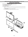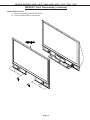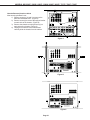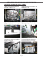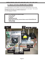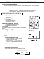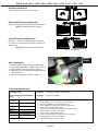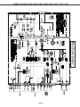
1
Ser vice
Manual
2005
MITSUBISHI ELECTRIC
DLP PROJECTION HDTV
V29 / V30 / V30+ / V31 CHASSIS
WD-52327
WD-52527
WD-62827
V29 Chassis
WD-52627
WD-62627
V30 Chassis
WD-52628
WD-62628
WD-73727
V30+ Chassis
WD-62827
WD-73827
V31 Chassis
WD-62927
WD-73927
Pb Solder
CAUTION:
Before servicing this chassis, it is important that the service person read the "SAFETY PRECAUTIONS" and
"PRODUCT SAFETY NOTICE" contained in this manual.
SPECIFICATIONS
•
•
•
•
Power Input
Power Usage
Light Engine
Light Source
• Channel Range
• Antenna Input
• Tuning (V29,V30)
:
:
:
:
:
:
AC 120V, 60Hz
See table on page 5
DLPTM (1920 x 1080 pixels)
120W [V29,V30(52"&62")]
150W [V30(73"),V30+,V31]
Air VHF - 2~13, UHF - 14~69
Analog Cable - 1~25
Digital Cable - 1~35
• Input Level
:
: VIDEO IN JACK (RCA Type)
1.0Vp-p 75Ω unbalanced
: AUDIO IN JACK (RCA Type)
-4.7dBm 43kΩ unbalanced
S-VIDEO IN JACK
(Y/C separate type)
Y:1.0 Vp-p C:0.286Vp-p(BURST)
75Ω unbalanced
: COMP / Y, Cr, Cb (RCA Type)
Y: 1.0 Vp-p Cr, Cb: 700mVp-p
: 2 RF 75Ω unbalanced
: 1 NTSC/ATSC/QAM
1 Out of Band for CableCARDTM
1 NTSC for PIP
: 2 NTSC/ATSC/QAM
1 Out of Band for CableCARDTM
2 NTSC for PIP
• Output Level
: VIDEO OUT JACK (RCA Type)
1.0Vp-p 75Ω unbalanced
: AUDIO OUT JACK (RCA Type)
-4.7dBm 4.7kΩ unbalanced
• Cabinet Dimensions
: See Table on page 5
• Digital
• Weight
: See table on page 5
: IEEE-1394 I/O Jacks
: Digital Audio Output
(RCA Type)
: HDMITM
:
MonitorLinkTM RS-232 Control
: Memory Card Reader
• Tuning (V30+, V31)
• Speakers (8 Ohms 10W)
: Two 1.5" Round
Two 5.5"x2.2" Oval
Pb Solder
: Lead-Free solder PWBs
• Design specifications are subject to change without notice.
MITSUBISHI DIGITAL ELECTRONICS AMERICA, INC.
9351 Jeronimo Road, Irvine, CA 92618-1904
Copyright © 2005 Mitsubishi Digital Electronics America, Inc.
All Rights Reserved
MODELS: WD-52627 / 52628 / 62627 / 62628 / 62827 / 62927 / 73727 / 73827 / 73927
CONTENTS
INTRODUCTION ................................................................................................................................ 5
Model Dimensions and Weight Specifiations ................................................................................... 5
PRODUCT SAFETY NOTICE ............................................................................................................. 5
SAFETY PRECAUTIONS ................................................................................................................. 6
DISASSEMBLY ................................................................................................................................. 7
Front Disassembly (WD-52627 / WD-52628 / WD-62627 / WD-62628............................................. 7
Front Disassembly (WD-62827) ...................................................................................................... 8
Front DisassembLY (WD-62927) ................................................................................................... 11
Front Disassembly (WD-73727 / WD-73827) ................................................................................. 15
Front Disassembly (WD-73927) .................................................................................................... 17
Rear Disassembly ........................................................................................................................ 19
Chassis Disassembly & Accessing PWBs ................................................................................... 20
Out of Cabinet Chassis Operation ................................................................................................. 26
52” & 62” Models Optical Engine Replacement ............................................................................. 29
73” Models Optical Engine Replacement ...................................................................................... 34
DIAMOND SHIELDTM Removal ........................................................................................................ 38
SERVICING THE LENTICULAR LENS AND FRESNEL SCREEN ..................................................... 39
Removal of the Lenticular Screen and Fresnel Lens ...................................................................... 39
Installation of the Lenticular Screen and Fresnel Lens ................................................................... 40
ADJUSTMENTS ............................................................................................................................... 41
Option Menu & Defaults ................................................................................................................ 41
LED Indicator Diagnostics ............................................................................................................. 42
Error Codes Operational Check ..................................................................................................... 43
Remote Operational Mode ............................................................................................................ 44
Service Adjustment Mode ............................................................................................................. 44
Service Adjustment Mode Operation .................................................................................... 44
Resetting Data to factory values and Transferring data ......................................................... 45
Optical Engine Adjustment ............................................................................................................ 46
Test Signal activation ........................................................................................................... 46
Preliminary ................................................................................................................................... 46
Accessing Mechanical Adjustments ............................................................................................. 47
Models WD-52627 / 62627 / 52628 / 62628 ......................................................................... 47
Models WD-63827 & WD-62927 .......................................................................................... 48
Models WD-73727 / 73827 &WD-73927 ............................................................................... 49
Locking Screws & Wedge Removal .............................................................................................. 50
Rotation Adjustmentt ........................................................................................................... 51
Keystone Distortion Adjustment ........................................................................................... 51
After Adjustment .................................................................................................................. 51
Hortizontal & Vertical Position.............................................................................................. 51
USING LEAD FREE SOLDER .......................................................................................................... 52
CHIP PARTS REPLACEMENT ......................................................................................................... 53
REPLACEMENT PARTS .................................................................................................................. 54
Parts Ordering .............................................................................................................................. 54
Critical and Warranty Parts Designation........................................................................................ 54
Parts Tolerance Codes .................................................................................................................. 54
Quick Reference List .................................................................................................................... 55
Page 3
MODELS: WD-52627 / 52628 / 62627 / 62628 / 62827 / 62927 / 73727 / 73827 / 73927
SERVICE PARTS LIST .................................................................................................................... 56
SCREEN ASSEMBLY PARTS LIST .................................................................................................. 67
WD-52627 / WD-52628 / WD-62627 / WD-62628 .......................................................................... 67
WD-62827 / WD-62927 ................................................................................................................. 68
WD-73727 / WD-73827 / WD-73927 ............................................................................................. 69
CIRCUITRY BLOCK DIAGRAMS ..................................................................................................... 71
Main Power Supply ....................................................................................................................... 71
Lamp Ballast DC Supply ............................................................................................................... 72
Fans Power Supply ....................................................................................................................... 72
Optical Engine Power Supply ........................................................................................................ 73
HDD Power Supply ((V30+ & V31 Only)........................................................................................ 73
Analog Video Signal Path ............................................................................................................. 74
Digital Video Signal Path .............................................................................................................. 75
HDD Record Signal Path ............................................................................................................... 76
Sound Signal Path ........................................................................................................................ 77
Command Input Circuitry ............................................................................................................... 78
Serial Data Control Lines .............................................................................................................. 78
Lamp Control Circuitry .................................................................................................................. 79
Lamp, Engine and Fan’s Protect circuitry ..................................................................................... 80
TV Guide On screen® ................................................................................................................... 80
SCHEMATIC DIAGRAMS .....................................................................................................................
PCB LAYOUT DIAGRAMS ...................................................................................................................
Page 4
MODELS: WD-52627 / 52628 / 62627 / 62628 / 62827 / 62927 / 73727 / 73827 / 73927
INTRODUCTION
This service manual provides service instructions for DLP Projection TV Models and Chassis:
Dimensions/Weight
MODEL
WD-52627
WD-52628
WD-62627
WD-62628
WD-62827
WD-62927
WD-73727
WD-73827
WD-73927
CHASSIS HEIGHT
V29
V30
V29
V30
V30+
V31
V30
V30+
V31
34 in.
"
40.5 in.
"
"
"
44.8 in.
"
"
WIDTH
DEPTH
WEIGHT
49.6 in.
"
58.3 in.
"
60.3 in.
"
69.9 in.
"
69.8 in.
18.6 in.
"
20.3 in
"
"
"
21.5 in.
"
"
121 lbs.
"
133 lbs.
"
"
"
165 lbs.
"
"
POWER
USAGE
295W
"
"
"
310W
330W
335W
350W
"
This service manual includes:
1. Assembly and disassembly instructions for the front and rear cabinet components.
2. Servicing of the Lenticular Screen and Fresnel Lens.
3. Servicing down to major components, chassis, PWBs, Light Engine, Lamp Ballast, etc..
4. Electrical adjustments.
5. Optical Adjustments.
6. Lead Free Soldering.
7. Chip parts replacement procedures.
8. Simplified circuit path diagrams.
The parts list section of this service manual includes:
1. Cabinet and screen parts.
2. Electrical parts.
Block diagrams of the above listed models are included in this service manual for better understanding of the circuitry.
PRODUCT SAFETY NOTICE
Many electrical and mechanical parts in television receivers have special safety related characteristics. These characteristics are often not evident from visual inspection nor can the protection afforded by them necessarily be obtained by
using replacement components rated for higher voltage, wattage, etc.
Replacement parts which have special safety characteristics are identified in this service manual.
Electrical components having such features are identified by shading on the schematic diagram and by bold type in
the parts list of this service manual. Therefore, the replacement for any safety part should be identical in value
and characteristics.
Pb Solder
The PWBs used in the V28 and V28+ chassis are constructed using Lead-Free solder. When
servicing use only recommended Lead-Free solder (refer to page 48).
CableCARD is a trademark of Cable Television Laboratories, Inc.
TV Guide On Screen is a registered trademark of Gemstar Development Corp.
HDMI is a trademark of HDMI Licensing, LLC.
Page 5
MODELS: WD-52627 / 52628 / 62627 / 62628 / 62827 / 62927 / 73727 / 73827 / 73927
SAFETY PRECAUTIONS
NOTICE:
WARNING:
1.
2.
Observe all cautions and safety related notes located inside the receiver cabinet and on the
receiver chassis.
Operation of this receiver outside the cabinet or with the cover removed presents a shock hazard
from the receiver's power supplies. Work on the receiver should not be attempted by anyone who is
not thoroughly familiar with the precautions necessary when working on high voltage equipment.
When service is required, observe the original lead dress. Extra precaution should be taken to
assure correct lead dress in the high voltage area. Where a short-circuit has occurred, replace those
components that indicate evidence of overheating.
WARNING ... RISK OF EYE INJURY
Do not look into the light source, lens or mirror when operating the TV
Leakage current check
Before returning the receiver to the customer, it is recommended that leakage current be measured according to the
following methods.
1. Cold Check
With the alternating current (AC) plug removed from the AC source, place a jumper across the two AC plug
prongs. Connect one lead of an ohm meter to the AC plug and touch the other lead to each exposed metal part
(i.e. antennas, handle bracket, metal cabinet, screw heads, metal overlay, control shafts, etc.), particularly any
exposed metal part that has a return path to the chassis. The resistance of the exposed metal parts having a
return path to the chassis should be a minimum of 1Meg Ohm. Any resistance below this value indicates an
abnormal condition and requires corrective action.
2. Hot Check ...Use the circuit shown below to perform the hot check test.
1. Keep switch S1 open and connect the receiver to the measuring circuit. Immediately after
connection, and with the switching devices of the receiver in their operating positions, measure the
leakage current for both positions of switch S2.
2. Close switch S1, energizing the receiver. Immediately after closing switch S1, and with the
switching devices of the receiver in their operating positions, measure the leakage current for both
positions of switch S2. Repeat the current measurements of items 1 and 2 after the receiver has
reached thermal stabilization. The leakage current must not exceed 0.5 milliampere (mA).
Page 6
MODELS: WD-52627 / 52628 / 62627 / 62628 / 62827 / 62927 / 73727 / 73827 / 73927
CABINET FRONT DISASSEMBLY
(WD-52627 / WD-52628 / WD-62627 / WD-62628)
SPEAKER GRILLE & BEZEL Removal
1) Pull the SPEAKER-GRILLE away from the cabinet to remove.
2) Pull the BEZEL from the cabinet.
SCREEN-ASSY Removal
1) Remove 10 screws (a) from the upper cabinet rear cover (3 screws on each side and 4 screws across the
top).
2) Remove screws (b) along the bottom of the SCREEN-ASSY (8 screws on 52 inch models, and 10 screws
on 62 inch models),
3) Unplug the LL connector to the front CONTROL-PANEL.
4) Lift the SCREEN-ASSY up slightly and then pull away from the cabinet.
Page 7
MODELS: WD-52627 / 52628 / 62627 / 62628 / 62827 / 62927 / 73727 / 73827 / 73927
WD-62827 Front Disassembly
FRONT PANEL CAPS Removal
1) Slide the FRONT PANEL CAPS towards
the sides of the unit.
2) Pull the FRONT PANEL CAPS from the
unit.
TOP TRIM and FRONT ESCUTCHEON Removal
1) Remove screw (a) to remove the TOP
TRIM.
2) Pull off the FRONT-ESCUTCHEONS.
Page 8
MODELS: WD-52627 / 52628 / 62627 / 62628 / 62827 / 62927 / 73727 / 73827 / 73927
WD-62827 Front Disassembly (continued)
SIDE-TRIM Removal
1)
Remove screws (a) and (b) on each
side of the unit.
2)
Pull off the SIDE-TRIM on each side.
BEZEL Removal
1) Remove screws (c) to remove the BEZEL.
Page 9
MODELS: WD-52627 / 52628 / 62627 / 62628 / 62827 / 62927 / 73727 / 73827 / 73927
WD-62827 Front Disassembly (continued)
SCREEN ASSY Removal
1) Remove screws (e) from the top and sides of the upper rear cover.
2) Remove screws (d) from the bottom of the SCREEN ASSY.
3) Lift the SCREEN ASSY up slightly and pull away from the cabinet.
Page 10
MODELS: WD-52627 / 52628 / 62627 / 62628 / 62827 / 62927 / 73727 / 73827 / 73927
WD-62927 Front Disassembly
FRONT ESCUTCHEONS, CARD READER/CONTROL Assy and PEDESTAL COVER Removal
1) Remove 6 outer screws “A” at the rear sides of the cabinet. (Do not remove inner screws).
2) Pull the Right and Left Front Escutcheons from the cabinet.
3) Pull the Pedestal Cover forward to remove.
Page 11
MODELS: WD-52627 / 52628 / 62627 / 62628 / 62827 / 62927 / 73727 / 73827 / 73927
WD-62927 Front Disassembly (continued)
TOP, BOTTOM and SIDES TRIM Removal
1) Remove screws (b) to remove the Top Trim.
2) Remove screws (c) to remove the Bottom Trim.
3) Remove screws (d) on both sides to remove the Side Trim
Page 12
MODELS: WD-52627 / 52628 / 62627 / 62628 / 62827 / 62927 / 73727 / 73827 / 73927
WD-62927 Front Disassembly (continued)
FRONT BEZEL Removal
1) Remove screws (e) from the FRONT-BEZEL.
2) Pull the FRONT-BEZEL from the cabinet.
Page 13
MODELS: WD-52627 / 52628 / 62627 / 62628 / 62827 / 62927 / 73727 / 73827 / 73927
WD-62927 Front Disassembly (continued)
SCREEN ASSEMBLY Removal
1) Remove screws (f) from the upper rear cover (3 at each side and 4 acrross the ).
2) Remove screws (g) at the bottom of the screen.
3) Lift the Screen Assembly slighly and pull away from the unit.
Page 14
MODELS: WD-52627 / 52628 / 62627 / 62628 / 62827 / 62927 / 73727 / 73827 / 73927
WD-73727 / WD-73827 Front Disassembly
CARD READER REMOVAL
1) Pull the two PANEL-FRONTs from the cabinet.
2) Remove screws ((a) from the Card Reader.
3) Slide the Card Reader and Control Assembly out the front of the TV.
(To remove the Card Reader completely unplut the connectore LL, CE1, J8202 and 1394.)
Page 15
MODELS: WD-52627 / 52628 / 62627 / 62628 / 62827 / 62927 / 73727 / 73827 / 73927
WD-73727 / WD-73827 Front Disassembly (continued)
GRILLE-SIDE REMOVAL
1) Remove screw (b) in the GRILLE-SIDE
LEFT and GRILL-SIDE RIGHT
2) Pull the two GRILLE-SIDEs from the unit.
SCREEN-ASSY REMOVAL
1) Remove screw (c) along the top and sides
of the upper rear cover. (4 across the top
and 3 on each side).
2) Remove two screw (d) on the bottom on the
SCREEN-ASSY.
3) Lift the SCREEN-ASY slightly and pull it
away from the TV.
Page 16
MODELS: WD-52627 / 52628 / 62627 / 62628 / 62827 / 62927 / 73727 / 73827 / 73927
WD-73927 Front Disassembly
CARD READER REMOVAL
1) From the rear of the TV, remove 2 screws “B”, and 6 outer screws “A” from
each side of the TV.
2) Pull of the right and left GRILLE-SIDEs.
.
Page 17
MODELS: WD-52627 / 52628 / 62627 / 62628 / 62827 / 62927 / 73727 / 73827 / 73927
WD-73927 Front Disassembly (continued)
SCREEN-ASSY Removal
1) Remove screws (f) along the top and sides of the upper rear cover. (4 across the top and 3 on each side).
2) Remove two screw (g) on the bottom on the SCREEN-ASSY.
3) Lift the SCREEN-ASY slightly and pull it away from the TV.
Page 18
MODELS: WD-52627 / 52628 / 62627 / 62628 / 62827 / 62927 / 73727 / 73827 / 73927
Cabinet Rear Disassembly
BACK-COVER Removal
1) Remove screws (a) and (b) from the the BACK-COVER.
2) Pull the BACK-COVER from the set.
Accessing the MIRROR from the rear (52 and 62 inch models ONLY)
1) Remove screws (c).
2) Pull the Rear Mirror Access panel from the unit.
Page 19
MODELS: WD-52627 / 52628 / 62627 / 62628 / 62827 / 62927 / 73727 / 73827 / 73927
Chassis Disassembly / Accessing PWBs
Note: Although not individually indicated, unplug the required connectors in each
disassembly step.
Chassis Sequence of Disassembly
REMOVE
Chassis Top Cover
(Fig. 1)
REMOVE
PWB-POWER
(Fig. 3)
REMOVE
Assy PWB-TERMINAL
(Fig. 2)
REMOVE
Chassis Top Shield
(Fig. 3)
REMOVE
PWBs MICRO / FMT/ RISER
(Figs. 4 & 5)
REMOVE
Chassis Rear Shield
(Fig. 6)
REMOVE
PWB-DM
(Fig. 7)
Page 20
MODELS: WD-52627 / 52628 / 62627 / 62628 / 62827 / 62927 / 73727 / 73827 / 73927
Chassis Removal from the cabinet
After removing the Rear Cover:
1) Remove screw (a), (b) and (c) to remove the
back terminal board cover. (Figure A)
2) Remove screw (d) to remove the support bracket
on each side of the chassis. (Figure B)
3) Remove the chassis mounting screws (e) on
each side of the chassis. (Figure (C)
4) Unplug all connectors to the chassis and
carefully slide the chassis from the cabinet.
Figure A
Figure B
Figure C
Page 21
MODELS: WD-52627 / 52628 / 62627 / 62628 / 62827 / 62927 / 73727 / 73827 / 73927
Chassis Cover Removal (Figure 1)
1) Remove the 3 screws (a).
2) Lift the Cover from the chassis.
Figure 1: Chassis Cover Removal
Assy PWB- TERMINAL Removal (Figure 2)
1) Remove 7 screws (b) to remove
the TERMINAL-INLAY.
2) Remove 3 screws (c) to remove
the Assy PWB-TERMINAL.
Figure 2: ASSY PWB-TERMINAL Removal
Page 22
MODELS: WD-52627 / 52628 / 62627 / 62628 / 62827 / 62927 / 73727 / 73827 / 73927
PWB-POWER Removal (Figure 3)
1) Remove four screws (d).
2) Disconnect all connectors to PWB-POWER.
3) Lift PWB-POWER from the chassis.
Chassis Upper Shield Removal (Figure 3)
1) Remove seven screws (e).
2) Lift the Shield from the chassis.
Figure 3: PWB-POWER and Chassis Upper Shield
Page 23
MODELS: WD-52627 / 52628 / 62627 / 62628 / 62827 / 62927 / 73727 / 73827 / 73927
PWB-MICRO Removal
Referring to Figures 4 & 5 .
1) Remove the 2 HDMI socket screws (f).
2) Remove 3 mounting screws (g) from PWB-MICRO.
2) Unplug PWB-MICRO from PWB-RISER
and remove it from the chassis.
Figure 5: PWB-MICRO Mounting Screws
Figure 4: HDMI Socket Screws
PWB-FORMAT & PWB=RISER Removal
Referring to Figures 6
After removing PWB-MICRO:
1) Remove screw (h).
2) Unplug the PWB-FORMAT and
PWB-RISER from PWB-DM.
Figure 6: PWB-FORMAT & RISER Removal
Page 24
MODELS: WD-52627 / 52628 / 62627 / 62628 / 62827 / 62927 / 73727 / 73827 / 73927
PWB-DM Removal
Chassis Rear Shield Removal (Figure 7)
1) Remove 7 screw ( j )
2) Remove 2 nuts ( j1 )
3) Pull off Chassis Rear Shield.
Figure 7: Chassis Rear Shield
PWB-DM Removal (Figures 8)
1) Remove 3 screws (k) holding the PWB-MICRO
Support Bracket.
2) Remove the Support Bracket.
3) Remove the five screws (m).
4) Remove the PWB-DM from the chassis.
Figure 8: PWB-DM Removal
Page 25
MODELS: WD-52627 / 52628 / 62627 / 62628 / 62827 / 62927 / 73727 / 73827 / 73927
OPERATING CHASSIS OUTSIDE OF CABINET
1) Remove screws from back terminal board.
Screws A = (7), B = (2), C = (2)
2) Remove support bracket screws D = (4), and
mounting screw E = (1)
A
D
B
C
E
3) Support bracket has latch that must be opened
before removing from unit
4) Remove mounting screw F = (1) on right side
of chassis behind bracket
latch
support bracket
F
5) Disconnect AC cord from connector PS and
disconnect connector CE1
6) Pull chassis from cabinet. Rotate to side as
pictured below and remove screws G = (2)
CE1
PS
G
Page 26
MODELS: WD-52627 / 52628 / 62627 / 62628 / 62827 / 62927 / 73727 / 73827 / 73927
7) Pictured below is proper wire routing, please
verify during re-assembly
8) Disconnect connector PL and remove screw
H = (1)
H
PL
PL
9) Remove connectors PC, PA1, PB, PD and
DVI cable
PC
PA1
10) Remove cover shield for Power PWB. Disconnect connectors FB, ES, KA, PD, PC, J7T01
J7T01
PB
DVI
PC
PD KA
PD
11) Remove screws from side and front of
chassis I =(4)
ES
FB
12) Remove screws from side of chassis J = (3)
and from terminal K = (3)
ck
Ba
t
Fron
J
I
Page 27
K
MODELS: WD-52627 / 52628 / 62627 / 62628 / 62827 / 62927 / 73727 / 73827 / 73927
13) Pull Terminal PWB from chassis assembly
and remove fan connector JD from Micro PWB
14) Setup power section next to remaining
chassis section as pictured below.
JD
NOTE: Unit can be operated without Terminal
PWB or Chassis Fan installed. Without Fan
connected, TV will shutdown if Micro PWB
(Bottom side) temperature becomes too hot.
NOTE: It is recommened to use a separate AC
cord. You can purchase one from the parts
department: P/N 246C351070
AC Cord
Bolt Table:
3
3
4
Screw Size: 3x12
12 Used @: A / C
Screw Size: 3x8
8 Used @: B / G / H / I / J / K
Screw Size: 4x16
16 Used @: D / E / F
Page 28
MODELS: WD-52627 / 52628 / 62627 / 62628 / 62827 / 62927 / 73727 / 73827 / 73927
52” & 62” Models
OPTICAL ENGINE REPLACEMENT
Pull engine from base and remove all the listed parts on this page and transfer them to new
engine. Then transfer EEPROM data and realign mechanical.
(See following pages for details)
LAMP DUCT
ENGINE-PWR-PWB
LENS CUSHION
BALLAST PLATE
ENGINE PLATE
INTERFACE PWB
BOTTOM PLATE
LAMP CARTRIDGE
GROUND STRAPS
LAMP FAN
(View from front)
Lamp Duct
Lens Cushion
Bottom Plate
Engine Plate
Lamp Fan
(120W Version)
(note on 150W version
Lamp Fan is in front)
(View from back)
Ballast Plate
Ballast Fan
Engine PWR PWB
Ballast Cover
Lamp Cartridge
Interface PWB
Page 29
MODELS: WD-52627 / 52628 / 62627 / 62628 / 62827 / 62927 / 73727 / 73827 / 73927
52” & 62” Models OPTICAL ENGINE REPLACEMENT (Details)
1) Remove screws (3)
2) Remove mounting screw
3) Disconnect JA, JF, LT connectors
4) Disconnect JC and CD connectors
LT
JC
JA
CD
JF
5) Remove DVI cable and disconnect
JE and DT connectors. Remove Ground Straps.
JE
6) Remove wire tie near support post
DVI
GROUND
STRAPS
DT
Page 30
MODELS: WD-52627 / 52628 / 62627 / 62628 / 62827 / 62927 / 73727 / 73827 / 73927
52” & 62” OPTICAL ENGINE REPLACEMENT (Details)
7) Remove (3) screws from Interface PWB
8) Remove CJ3 connector from Interface PWB
CJ3
9) Remove (2) screws from Side Lock
10) Route wiring so that it does not snag
on support post.
11) Disconnect PA1 and J3 connectors
and remove Engine-PWR-PWB
12) Pull Optical Engine from cabinet. (Note:
Slight twisting motion may be required)
J3
PA1
Page 31
MODELS: WD-52627 / 52628 / 62627 / 62628 / 62827 / 62927 / 73727 / 73827 / 73927
52” & 62” OPTICAL ENGINE REPLACEMENT (Details)
13) Remove (3) screws from Lamp Duct
14) Remove (2) screws from Lamp
Cartridge - and remove Lamp Cartridge
15) Remove (4) screws from Ballast Plate
16) Remove Bottom Plate from Engine Plate.
Remove (5) screws C - B - A (in that order)
C
Remove Screws “C” under the Bottom Plate.
A
B
Remove Screws “B” from the rear of the Engine.
Remove Screws “A” from the top of the Engine..
Page 32
MODELS: WD-52627 / 52628 / 62627 / 62628 / 62827 / 62927 / 73727 / 73827 / 73927
52” & 62” Models OPTICAL ENGINE REPLACEMENT (Details)
17) Be sure not to misplace spring
18) Remove (1) screw from plate
(A), (4) screws from fan (B), (2)
screws from side lock (C) and (2)
grounding strap screws (D)
C
D
Spring
A
B
19) Transfer LENS COVER from
service part to defective part
Reassembly:
1) Attach LENS CUSHION BASE to Engine
Lens Cushion Base
Follow above steps in reverse order
TIP: Lift and group wiring on left
side of engine when installing
Mechanical Alignment: Adjustment is required after engine has been removed. Please follow steps
in the adjustment section of this manual.
Data: Index Delay Data needs to be transfered from Engine to E2P PWB:
< MENU + 2457 + 0 >
Select -> COPY LIGHT ENGINE EEPROM TO DM
PRESS ENTER
Page 33
MODELS: WD-52627 / 52628 / 62627 / 62628 / 62827 / 62927 / 73727 / 73827 / 73927
73 “ Model’s OPTICAL ENGINE REPLACEMENT
Pull engine assembly from the cabinet, and remove the Optical Engine from the base.
Remove all the listed parts on this page and transfer them to new engine. Then transfer
EEPROM data and realign the mechanical adjustments.
(See following pages for details)
Remove the following parts from the engine:
• Lamp Cartridge
• Joining Plate
• Lamp Fan
• ENGINE-PWR-PWB
• Bottom Plate Assembly with the Ballast and the PWB-INTERFACE
• Rubber Wedge
• Ground Straps
ENGINE-PWR
PWB
LAMP
FAN
JOINING
BRACKET
BALLAST
LAMP
CARTRIDGE
PWB
INTERFACE
BASE PLATE
ASSEMBLY
RUBBER
WEDGE
GROUND
STRAPS
J
Page 34
MODELS: WD-52627 / 52628 / 62627 / 62628 / 62827 / 62927 / 73727 / 73827 / 73927
73” Models OPTICAL ENGINE REPLACEMENT (Details)
Engine Assembly removal from the cabinet.
After removing the Back Cover:
1) Remove 4 screws (a) to remove the Vertical Support and DM Fan Cover.
2) Remove screw (b) to remove the Lamp Box cover.
a
LAMP
COVER
b
VERTICAL
SUPPORT
DMD FAN
COVER
3) Remove 3 Screws (c) and disconnect all leads to the Optical Engine.
4) Remove screw (d) from PWB-INTERFACE.
4) Carefully slide the Light Engine from the cabinet.
c
d
c
Page 35
MODELS: WD-52627 / 52628 / 62627 / 62628 / 62827 / 62927 / 73727 / 73827 / 73927
73” Models OPTICAL ENGINE REPLACEMENT (Details)
Engine removal from the Base Plate Assembly.
1) Remove 2 screws (e) and 2 screws (f) to remove the Joining Bracket.
f
Joining
Bracket
e
2) Remove the Rubber Wedge and 2 screws (g) at the rear of the Engine.
g
Rubber
Wedge
3) Remove screw (h) on top of the Engine, and unplug the ballast leads from the Lamp Box.
Unplug
Ballast
Leads
h
Page 36
MODELS: WD-52627 / 52628 / 62627 / 62628 / 62827 / 62927 / 73727 / 73827 / 73927
73” Models OPTICAL ENGINE REPLACEMENT (Details)
Engine removal from the Base Plate Assembly (continued)
4) Carefully lift the Engine from the Base Plate.
CAUTION: Do Not lose the spring sitting in the Base Plate Assembly.
DO NOT
LOSE
Engine Installation
Reverse the procedure to install the new Engine.
After Replacing the Optical Engine:
Transfer Data from the new Engine to the DM (refer to page 45).
Page 37
MODELS: WD-52627 / 52628 / 62627 / 62628 / 62827 / 62927 / 73727 / 73827 / 73927
DIAMOND SHIELD REPLACEMENT
(WD-62927 / WD-73927 Only)
To Remove the Diamond Shield:
1) While wearing soft cotton gloves,
loosen the sides of the Diamond Shield
by pressing a small plastic card (the
size of a standard credit card or a
clean, plastic, putty knife) into the
middle of the side slot. The Diamond
Shield side will snap out of the top,
middle and bottom clips. Loosen both
sides before proceeding to step 2.
2) After the sides are free, gently push
down on the top of the Diamond
Shield. It will slide out of the top
channel.
3) Carefully pull the screen up to it from
the bottom channel. Store the Diamond
Shield in a clean dust free area, where
it will not be scratched.
To Install the Diamond Shield:
4) Slide the Diamond Shield into the bottom
channel, making sure it fits securely.
5) Press gently on the top of the Diamond
Shield to slightly bow the screen toward
you. Insert the top of the Diamond Shield
into the top channel. It should fit securely.
6) At each side, gently press the top, middel
and bottom of the Diamond Shield to snap it
back into place.
WARNING
Sharp edges! Always wear gloves to handle, lift,
install and remove the Diamond Shield.
Page 38
MODELS: WD-52627 / 52628 / 62627 / 62628 / 62827 / 62927 / 73727 / 73827 / 73927
SERVICING THE LENTICULAR SCREEN AND FRESNEL LENS
CAUTION:
Wear gloves when handling the Lenticular Screen and Fresnel Lens.
This prevents cuts and finger prints. Do not place Fresnel Lens in the sun.
This may cause fire and heat related injuries.
Lenticular Screen and Fresnel Lens Removal
1. Remove the screen assembly as shown in the Cabinet Disassembly procedure.
2. Remove the four screws (a) to remove the bottom of the SCREEN-FRAME-BOTTOM . (Figure 1)
3. From the rear of the screen assembly, carefully slide the Lenticular Screen and Fresnel Lens combination
from the Screen Frame. (Figure 2)
Note: When separating the Lenticular Screen from the Fresnel Lens, use caution
while prying the Screen and Lens apart. Use a slot type screw driver, and
remove the pressure sensitive double sided tape.
Figure 1
Page 39
MODELS: WD-52627 / 52628 / 62627 / 62628 / 62827 / 62927 / 73727 / 73827 / 73927
SERVICING THE LENTICULAR SCREEN AND FRESNEL LENS
Lenticular Screen and Fresnel Lens Installation
Note: Store the Lenticular Screen and Fresnel Lens in a cool dry place. High humidity may
deform the Lenticular Screen and Fresnel Lens.
1. Apply double coated tape (Part #LENS-TAPE) along the top rear edge of the Lenticular Screen, as shown
below. Refer to the table below for the tape length.
2. Sandwich the Fresnal Lens and Lenticular Screen together. The Lenticular Screen label must be towards
the front and the Fresnel Lens label towards the rear. (Figure 2)
3. Apply pressure at the top edge to bond the screens together.
4. Reverse the Screen Removal procedure and insert the screens in the Screen Fame Assembly.
Figure 1
Model
Tape Length
WD-52627
WD-52628
45.3 in.
WD-62627
WD-62628
WD-62827
WD-62927
WD-73727
WD-73827
WD-73927
Page 40
53.9 in.
63.5 in.
MODELS: WD-52627 / 52628 / 62627 / 62628 / 62827 / 62927 / 73727 / 73827 / 73927
OPTION MENU
1. Press the “MENU” button on the remote hand unit.
2. Press the buttons “2”, “4”, “7” and “0” in order.
(The screen will change to the option menu.)
Initial Main Menu Defaults
Setup Menu
Language
Combine Channel View
Clock
Clock Setting
Time
Date
Time Zone
Daylight Savings Time
Timer
Lamp Reminder
Software Version
NetCommand Menu
Edit
Icon Order
Transport Menu
Fixed Channel for Cable Box
Record
Record
Channel
Record to
Duration
Start Time
Day
Record List
Default Record Device
Analog Recordings
Channel
Antenna
Prefer Digital
Channel
Memory
Name
SQV
Signal Strength
Captions Menu
Analog Captions
Background
Digital Caption
Appearance
DigitalSettings
Font
Size
Color
Background
Opacity
Background Opacity
V-Chip Lock Menu
V-Chip
TV Rating
FV-Fantasy Violence
D-Sexual Dialog
English
-Manual
12:00pm
-----
--On
3 (gray out)
2
-1 hr
---Gray out
Anamorphic
1
-2
Added
---On if Mute
Gray
On if Mute
Default
Font 3
Large
White
Black
Translucent
Translucent
Off
TV-PG
Enable
Enable
L-Adult Language
S-Sexual Situationss
V-Violence
Programs Not Rated
Movie Rating
V-Chip Time
Start
Stop
Lock by Time
Lock by Time
Lock Time
Unlock Time
Front Button Lock
Audio/Video
A/V Memory Reset
Settings
Audio
Bass
Treble
Balance
Surround
Listen to (Analog Only)
Level Sount (Analog Only)
Language (Digital Only)
Video
Contrast
Brightnes
Sharpness
Color
Tint
Color Temp
Video Noise
Film Mode (Auto)
Define Edge
Color Balane
Video Mute
black Enhancement
TV Speakers
TV Volune
PIP Source
PIP Position
POP Position
PIP/POP Format
Format
Ant-1,2 (480i/480p)
Ant -1,2 (HD Digital)
Input 1,2,3
Comp-1,2,3
HDMI-1,2 (Video)
HDMI-2(PC)
Card Reader Video
Analog PC (v31 ONLY)
Page 41
Enable
Enable
Enable
Enable
PG
12:00pm
12:00pm
On
12:00pm
12:00pm
Off
Ant-1
50%
50%
50%
Off
Stereo
On
English
100%
50%
50%
50%
50%
High
Standard
On
On
On
On
On
30%
Ant 1 003
Lower Right
Right Half
Double Window
Stretch
Standard
Standard
Standard
Standard
Standard
Standard
Standard
MODELS: WD-52627 / 52628 / 62627 / 62628 / 62827 / 62927 / 73727 / 73827 / 73927
A/V RESET DEFAULT SETTINGS (By Input)
INPUTS Component 1394 when HDMI 1/2
Ant 1/2
1/2/3
1/2/DTV
connected (Video)
Bright
Bright
Bright
Bright
Bright
MAX
MAX
MAX
MAX
MAX
Center
Center
Center
Center
Center
Center
Center
Center
Center
Center
Center
Center
Center
Center
Center
Center
Center
Center
Center
Center
High
High
High
High
High
Manual/
Manual/
Manual/
Manual/
Manual/
Center
Center
Center
Center
Center
A/V Memory
Bright/Natural
Bright Contrast
Bright Brightness
Color
Tint
Sharpness
Color Temp.
Perfect Color
Deep Field Imager
On
On
On
(V30-V31)
Video Noise
Standard Standard
Standard
On
On
On
TV Film Mode (Auto)
SharpEdge (V30-V31)
On
On
On
Center
Center
Center
Bass
Treble
Center
Center
Center
Center
Center
Center
Balance
Surround
OFF
OFF
OFF
Stereo
N/A
N/A
Listen To
Level Sound
On
On
On
Language
English
N/A
N/A
(Digital Only)
Vertical Position
N/A
N/A
N/A
Horizontal Position
N/A
N/A
N/A
Fine Detail
N/A
N/A
N/A
*Analog PC mode is only available on V31 models
On
On
N/A
N/A
On
Center
Center
Center
OFF
N/A
On
HDMI-2 (PC)
Analog PC*
N/A
MAX
Center
N/A
N/A
N/A
High
N/A
Card 1~4
Bright
MAX
Center
Center
Center
Center
High
Manual/
Center
On
Standard
On
On
Center
Center
Center
OFF
N/A
On
N/A
N/A
N/A
N/A
Center
Center
Center
OFF
N/A
On
N/A
N/A
On
Center
Center
Center
OFF
N/A
On
English
N/A
N/A
English
N/A
N/A
N/A
N/A
N/A
N/A
Center
Center
Center
N/A
N/A
N/A
A. A/V Memory
Each of the external inputs has its’ own Audio/Video Memory. A change in an A/V setting at a specific input is
stored in memory for that specific input.
B. A/V Reset
1. On the front panel, pressing GUIDE and FORMAT at the same time initializes all A/V Memories.
2. The AV Reset in the user’s menu initializes only the selected input’s A/V Memory.
LED Indicator Diagnostics
The front panel LEDs provide an indication of the sets operation, and the possible cause of a malfunction. There are three
front panel LEDs, “Power”, “Status” and “Lamp”. Which LED is
lit, the color and whether it is blinking or steady indicate the
current status, or a possible malfunction.
Normal LED Indications
POWER
LED
Off
Green
STATUS
LED
Off
Off
Off
Off
Blinks
Green
Slo Blinks
Green
LAMP
LED
Off
Off
Blinks
Green
Power
Status
Stby
P-0N
After Turn
Off
Off
Off
Stby
Booting after AC applied
Off
Off
Stby
On Timer is set
Page 42
Condition
Off
Power On
Lamp Fan On for 1 minute
MODELS: WD-52627 / 52628 / 62627 / 62628 / 62827 / 62927 / 73727 / 73827 / 73927
Abnormal LED Indications
POWER
LED
STATUS
LED
LAMP
LED
Off
Yellow
Off
Off or On
Off
Yellow
Off
Off
Blinks
Yellow
Power
Status
Low
Power
No
change
Low
Power
Off
Off
Off
Off
Blinks
Yellow
Off
Blinks
Red
Off
"
Red
Stby
Low
Power
Red
Off
Off
"
Condition
Excess Temperature
120w usage time over 7000 Hrs.
150W usage time over 3500 Hrs.
Lamp Cover open
Filter Cover Open
Lamp did not turn On
Fan Stopped
Circuit failure (short or DVI
connector unplugged)
3. Error Code Operational Check
Note: The TV must be in “Shut Down” and not have been switched Off, to perform the Error Code Operational Check. When the TV is switched Off, the code automatically resets to “12” No Error.
Pressing the front panel “DEVICE” and “MENU” buttons at the same time, and holding for 5 seconds,
activates the Error Code Mode. The LED flashes denoting a two digit Error Code, or indicating no problem
has occured since the last Initalization.
Note: The front panel buttons must be used, NOT those on the Remote Control.
•
•
•
•
The number of flashes indicates the value of the MSD (tens digit) of the Error Code.
The flashing then pauses for approximately 1/2 second.
The LED then flashes indicating the value of the LSD (ones digit) of the Error Code.
The Error Code is repeated a total of 5 times.
Example: If the Error Code is “23”, the LED will flash two times, pause, and then flash three times.
4. Error Codes
The Error Code designations indicating malfunction, or no malfunction, are listed below:
Error Codes
Error Codes
12
22
32
34
35
36
37
38
39
41
42
44
46
47
48
51
52
55
"DEVICE" & "MENU"
Description
No error detected
Recovery from Reset
Lamp cover is Open
Lamp abnormality
DM Fan failed (Chassis Fan)
Exhaust or Lamp Ballast Fan failed
DMD Engine Fan failed
Lamp temperature abnormally high
DMD temperature abnormally high
Short is detected (Standby Power Supplies)
Lamp Fan failed
DVI cable between Format and Engine disconnected
DMD Temp. Sensor not detected (check DT connector))
DM Temperature too high
Engine power supply short detected
Speaker Drive circuit short detected
HDD excess temperature (V30+ & V31 only)
HDD Fan Stopped (V30+ & V31 onlyt)
Page 43
MODELS: WD-52627 / 52628 / 62627 / 62628 / 62827 / 62927 / 73727 / 73827 / 73927
Remote Control Operational Modes
There are two Remote Hand Unit Operational Modes, “Standard” and “NetCommandTM”. The Remote is initially
in the “Standard” mode. The “NetCommandTM” mode is used when controlling Home Theater devices using
NetCommandTM. To change the Remote Operational Mode:
• Set the Remote to the TV Layer
• Point the Remote away from the TV.
• To change to “NetcommandTM” ... Hold the “Power” button and press “9-3-5” in sequence.
• To change to “Standard” ... Hold the “Power” button and press “0-0-0” in sequence.
SERVICE ADJUSTMENTS
There are only 5 Service Adjustments required in these models:
Two Electrical Adjustments
• Horizontal Centering
• Vertical Centering
Three Mechanical Adjustment
• Picture Rotation
• Horizontal Keystone Distortion
• Vertical Keystone Distortion
Measuring equipment and Jigs
• No additional Test Equipment is required.
• Conventional Electrical Hand Tools.
Test signal
An internally generated Test Signal is used, no additional external signals are
required.
Circuit Adjustment Mode
On these models, the Circuit Adjustment Mode is used only for:
• Test Signal activation
• Horizontal Centering
• Vertical Centering
These adjustments may only be performed using the remote
hand unit.
1. Activating the adjustment mode
1. Press the “MENU” button on a remote hand unit.
(The “MENU” display will appear.)
2. Press the buttons “2”, “4”, “5” and “7” in that order.
(The screen will change to the adjustment mode.)
If not changed to the adjustment mode, repeat steps
1 and 2.
2. Test Signal Activation
When in the Circuit Adjustment mode, press “REWIND” on the remote control to activate the test pattern. This
pattern is used for both electrical and mechanical adjustments.
3. Adjustment Function Selection
Use the “AUDIO” button to select a specific Adjustment Function.
Doubler
Functions
Page 44
fmt
MODELS: WD-52627 / 52628 / 62627 / 62628 / 62827 / 62927 / 73727 / 73827 / 73927
3. Adjustment Selection
Use the “VIDEO” button to select a specific electrical ajustment, “1 HPOS” or “2 VPOS”.
4. Adjusting Data
After selecting an adjustment item, use the “UP” and “DN” buttons to change adjustment data.
ª If the “UP” button is pressed, the adjustment data increases.
ª If the “DN” button is pressed, the adjustment data decreases.
5. Saving data
Press “ENTER” to save the adjustment data in memory.
The display characters go red for approx. one second in this step.
Note: If the circuit adjustment mode is terminated without pressing
“ENTER”, changes in adjustment data are not saved.
6. Terminating the circuit adjustment mode
Press the “MENU” button on the remote hand unit twice to terminate the adjustment mode.
Note: The adjustment mode can be also terminated by turning the
power off.
Resetting Data to Factory Values
1) Enter the Service Adjustment Mode ... Press “MENU-2-4-5-7”
2) Press “0” when in the Service Mode ... Four choices appear at the top of the screen.
Data Transfer
Display
Copy Engine E2PROM to DM
Restore Backup
UPLOAD TERMINAL BOARD DATA
Download WB Alignment to FMT
MENU-2-4-5-7-0
Description
Transfers Engine data to DM E2PROM
Restores data to factory values
DO NOT USE
Transfers Engine data to FMT
3) User UP & DN keys to highlight the desired choice, the Press “ENTER”
Page 45
MODELS: WD-52627 / 52628 / 62627 / 62628 / 62827 / 62927 / 73727 / 73827 / 73927
Optical Engine Adjustments
Test Signal Activation
1) Press “MENU-2-4-5-7” (Service Mode)
2) Press “REW” (Test Pattern).
Red = 4% overscan
White = 5% overscan
Green = 6% overscan
Cyan = 7% overscan
Yellow = 10% overscan
Required Tools
•
•
•
4mm Hex Wrench (10 inches long minimum )
5mm Allen Wrench ( 10 inches long minimum)
10mm Hex or Phillips driver.
Prelminary
Mechanical Optical Engine Adjustments are made using the UNIT-ADJUSTER shown in Figure 1. The UNIT-ADJUSTER
is mounted under the Light Engine on the Engine Plate. It is accessed from the front of the set through the opening for
the Card Reader. Refer to the model specific Disassembly Instructions and remove the:
• Back Cover
• Speaker Grille
• Card Reader (Refer to page 43)
[A-1]
VERT. KEYSTONE
4mm Hex
[A-2]
ROTATION
4mm Hex
[B-1]
LOCKING SCREW
5mm Allen Wrench
Figure 1: Unit-Adjuster
Page 42
[A-3]
HORIZ. KEYSTONE
4mm Hex
MODELS: WD-52627 / 52628 / 62627 / 62628 / 62827 / 62927 / 73727 / 73827 / 73927
ACCESSING MECHANICAL ADJUSTMENTS
WD-52627 / 62627 / 52628 / 62628
1) Pull Speaker Grille out.
2) Remove (2) screws (A) and pull Card Reader to access adjustment.
Speaker Grille
A
WD-62827
1) Remove (6) screws (A) to remove card reader cover.
2) Remove (2) screws (B) to remove card reader.
B
A
Card Reader
Card Reader
Cover
Page 47
MODELS: WD-52627 / 52628 / 62627 / 62628 / 62827 / 62927 / 73727 / 73827 / 73927
WD-62927
1) Pull Pedestal Cover out. Adjustment is now accessable.
Adjustment Access
Pedestal Cover
WD-73727 / 73827
1) Pull the Panel Caps from the unit to remove them.
2) Remove (4) screws (A) to pull out entire Card Reader Unit.
A
A
Page 48
MODELS: WD-52627 / 52628 / 62627 / 62628 / 62827 / 62927 / 73727 / 73827 / 73927
WD-73927
1) Remove (16) screws (A). 8 on each side. (Remove only the outside screws. Do not remove inside
screws, they are for the Screen Frame)
2) Pull Front Panel Escushions from unit.
A
A
A
A
3) Remove (8) screws (B) and remove the Pedestal Cover. Mechanical adjuster is now accessable.
B
B
Locking Screws and Wedge Removal
Before mechanical adjustments can be made, locking screws must be loosened.
•
•
[B-1] is located on the front of the UNIT-ADJUSTER. (Figure 1)
In 52” and 62” models [B-2] is accessible from the rear of the unit on the right side of the
Optical Engine (from the rear). (Figure 2)
WARNING: DO NOT loosen [B-2] too far. The nut on
the other side may drop off. Then then Optical Engine must be
removed to re-install the nut.
[B-2]
Figure 2: 52” & 62” Side Locking Screw
Page 49
MODELS: WD-52627 / 52628 / 62627 / 62628 / 62827 / 62927 / 73727 / 73827 / 73927
Locking Screws (continued)
•
•
In 73” models, loosen the 4 screws [C] in the Joining Bracket. (Figure 3)
Remove the rubber wedge shown in
[C]
[C]
Figure 3: Joining Bracket Lock Screws
WEDGE
Figure 4: Rubber Wedge
ADJUSTMENT PROCEDURES
Adjustment Locations
[A-2]
The Mechanical Adjustements are accessed
though the opening for the Card Reader.
Locations of the Adjustmentts are shown
below.
[A-1]
[A-3]
CAUTION: Do Not force an adjustment past the end of it’s range,
UNIT-ADJUSTER damage may
result.
[B-1]
Figure 4: Adjustment Locations
Page 50
MODELS: WD-52627 / 52628 / 62627 / 62628 / 62827 / 62927 / 73727 / 73827 / 73927
Rotation Adjustment
Adjust [A-2] to remove any picture rotation
Horizontal Keystone Adjustment
Adjust [A-3] to remove horizontal keystone distortion.
NOTE: Vertical Positioning may shift
Vertical Keystone Adjustment
Adjust [A-1- To remove vertical keystone distortion.
[A-1] can only be accessed by the front access hole
shown above.
NOTE: Horizontal Positioning may shift.
Figure 5: Adjustments
RUBBER
WEDGE
After Adjustment
1) Slide the rubber wedge under the Engine slowly
until it make solid contact. (Figures Figures 3 & 6)
2) Tighten side Locking Screws [B-2]. (Figure 2)
3) Check the Picture, re-adjustment may be required
(usually rotation).
4) Tighten front Locking screw [B-1]. (Figure 3)
Figure 6: Wedge Insertion
Electrical Adjustments
[Format Circuit]
Purpose:
Horizont/Vertical Positi0n Adjustment
Symptom: Picture is off center.
Measuring
Instrument
Test Point
----
Ext. Trigger
------
Measuring
Range
------
Input Signal
Internal Test Patern.
Input Terminal
Video
1.
2.
3.
4.
5.
6.
7.
8.
9.
10.
To center the picture on the screen.
Press “MENU-2-4-5-7”, activates the Service Mode..
Select the “FORMAT” function (AUDIO button).
Press “REWIND”, activates the Overscan Test Pattern
Select “Item 1” HPOS (VIDEO button).
Use the ADJUST buttons to center the picture horizontally.
Press ENTER to save the new setting.
Select “Item 2” VPOS (VIDEO button).
Use the ADJUST buttons to center the picture vertically.
Press ENTER to save the new setting.
Press MENU to exit the Service Mode.
Page 51
MODELS: WD-52627 / 52628 / 62627 / 62628 / 62827 / 62927 / 73727 / 73827 / 73927
Pb Solder
Using Lead Free Solder
•
•
The above symbol indicates Lead (Pb) Free solder was
used during the construction of PWBs. Only Lead
Free solder should be used when servicing these
PWBs.
Solder must be compatible with that used by the
manufacturer. Leaded solder can not be used on
PWBs manufactured with Pb-free solder. The Mitsubishi standard for service requires the use of Tin-SilverCopper (Sn-96.5, Ag-3.0, Cu-0.5). It can be obtained
through the Parts Department.
Order part number: PB FREE SOLDER
Lead Free solder has a higher melting point, and does
not “wet” as well as leaded solder. This means it does
not adhere as readily to the solder iron tip, and the
surface to be soldered. To counteract this, the flux
used is more corrosive.
•
•
•
•
The flux is more corrosive.
The time required for a good solder connection may
take longer.
Poor wet-ability can cause solder balls.
Higher temperatures can cause flux spattering.
Soldering iron tip life is shortened.
Dull finish solder joints (not shiny) can appear to be
a “cold” solder joint.
In general a tip temperature of 700° F will usually provide
good results.
Displays used to indicate Pb-free
PCBs will be marked, indicating the level of Pb-free construction. Table 1 defines the levels by phase and shows
the different symbols that will be displayed on the PCB.
Additionally, a PCB constructed using Pb-free solder may
be simply marked LFS.
When possible, the indication will be placed close to the
part number that is screened onto the PCB (not the part
The following cautions must be taken when using Pb
label). Figure 1 is an example of a PCB showing the
Free solder.
display and its location.
• Higher temperatures can cause the PWB to
warp, detaching surface mount
Pb-Free
Short Display (When the
components.
Phase
Definition
Display
area is too small)
• Higher temperatures may
Phase-1 PCB's constructed using
Pb-free solder.
cause thermal damage to
components.
• Higher temperatures can cause
plastics, such as connectors, Phase-2 Solder, PCB surface
finishing and component
relays, LEDs electrolytic
lead plating is Pb-free.
capacitors, etc. to melt or
Components may have
warp.
internal Pb.
• Higher temperatures can cause Phase-3 Solder, PCB surface
finishing and components
surface oxidation resulting in
are Pb-free. (100% Pbpoor solder spread-ability and
free)
wet-ability.
Table 1: Pb-Free Phases and Symbols
Pb-Free
Display
Figure 2: Pb-Free display on PWB
PAGE 52
Pb Solder
Pb S
Pb Joints
Pb J
Pb PCA
Pb P
MODELS: WD-52627 / 52628 / 62627 / 62628 / 62827 / 62927 / 73727 / 73827 / 73927
CHIP PARTS REPLACEMENT
Some resistors, shorting jumpers (0 Ohm resistors),
ceramic capacitors, transistors and diodes are chip parts.
The following precautions should be taken when replacing
these parts.
Chip Parts Removal (Transistors)
1. Melt the solder of one lead and lift the side of
that lead upward.
2. Simultaneously melt the solder of the other
two leads and lift the part from the PCB.
Cautions:
1. Use a fine tipped, well insulated soldering iron
and tweezers.
2. Melt the solder and remove the chip parts
carefully so as not to tear the copper foil from
the printed circuit board.
3. Discard removed chips; do not reuse them.
4. Do not apply heat for more than 3 (three)
seconds to new chip parts.
5. Avoid using a rubbing stroke when soldering.
6. Take care not to scratch, or damage the chip
parts when soldering.
7. Supplementary cementing is not required.
Chip Parts Removal (Resistors, Capacitors, etc.)
1. Grasp the part with tweezers. Melt the solder
at both sides alternately, and remove one side
of the part with a twisting motion.
2. Melt the solder at the other side and remove
the part.
Replacement
1. Presolder the contact points on the circuit
pattern.
2. Press the part downward with tweezers and
apply the soldering iron as shown.
PAGE 53
MODELS: WD-52627 / 52628 / 62627 / 62628 / 62827 / 62927 / 73727 / 73827 / 73927
REPLACEMENT PARTS
Parts Ordering
To expedite delivery of replacement parts orders, specify the following:
1. Model Number/Serial Number
2. Part Number and description
3. Quantity
Note: Unless complete information is supplied, delay in processing of orders will result.
Critical and Warranty Parts Designation
Critical Electrical Components are indicated by Bold Type in the Parts List, and in the schematic
diagrams by shading.
Warranty Return Parts are indicated in the Parts List with an (*).
Parts Tolerance Codes
Refer to the following chart for tolerance characteristics of electrical components.
MARK
B
C
D
F
G
J
K
Tolerance %
± 0.1
± 0.25
± 0.5
±1
±2
±5
± 10
MARK
M
N
V
X
Z
P
Q
Tolerance %
± 20
± 30
± 10
+ 40
+ 80
+ 100
+ 30
-20
-20
-0
-10
MARK
M
N
V
X
Z
Tolerance (pF)
± 0.1
± 0.25
± 0.5
±1
±2
PAGE 54
MODELS: WD-52627 / 52628 / 62627 / 62628 / 62827 / 62927 / 73727 / 73827 / 73927
QUICK REFERENCE FOR COMMON PARTS
Major PWB Assemblies
PWBs
ASSY-PWB-POWER2
ASSY-PWB-TERMINAL
ASSY-PWB-MICRO
ASSY-PWB-DM
ASSY-PWB-V29FMT
ASSY-PWB-RISER
ASSY-PWB-DEMOD1
ASSY-ENG-POWER
PART NO.
934C159001
934C159002
934C150005
934C150006
934C151005
934C151006
934C152005
934C152006
934C152007
934C160001
934C160002
934C134002
934C134005
935D819001
935D839001
955C283001
MODELS
WD-52627 / 52628 / 62627 / 62628 / 73727
WD-62827 / 62927 / 73827 / 73927
WD-52627 / 52628 / 62627 / 62628 / 73727
WD-62827 / 62927 / 73827 / 73927
WD-52627 / 52628 / 62627 / 62628 / 73727
WD-62827 / 62927 / 73827 / 73927
WD-52627 / 62627
WD-62628 / 62628 / 72727
WD-62827 / 62927 / 73827 / 73927
WD-52627 / 52628 / 62627 / 62628 / 62927 / 73727 / 73827
WD-62827 / 73927
WD-52627 / 52628 / 62627 / 62628 / 73727
WD-62827 / 62927 / 73827 / 73927
All models
WD-62827 / 62927 / 73827 / 73927
All models
OPTICAL COMPONENTS
Component
LIGHT ENGINE
PWB-BALLAST
LAMP CARTRIDGE
Part No.
938P017010
938P017020
938P019020
938P019010
938P118010
938P978020
915P026010
915P027010
Models
WD-52627 / 52628
WD-62627 / 62628
WD-62827 / 62927
WD-73727 / 73827 / 73927
WD-62827 / 62927 / 73727 / 73827 / 73927
WS-52627 / 52628 / 62627 / 62628
WS-52627 / 52628 / 62627 / 62628
WD-62827 / 62927 / 73727 / 73827 / 73927
MIRROR & SCREEN PARTS
MODEL
WD-52627
WD-52628
WD-62627
WD-62628
WD-62827
WD-62927
WD-73727
WD-73827
WD-73927
MIRROR
767D079010
"
767D079020
"
"
"
767D079030
"
"
LENTICULAR
SCREEN
491P178040
"
492P178030
"
"
"
491P176050
"
"
FRESNEL
LENS
491P177040
"
491P177030
"
"
"
491P175050
"
"
DIAMOND
SHIELD
760D656010
760D656030
760D656040
MISCELLANEOUS PARTS
CHASSIS
Chassis Fan
Lamp Fan
DMD Fan
V29
V30 / V30+ / V31
299P288010
"
299P298010
"
299P299010
"
PAGE 55
Remote
Control
299P278020 290P122020
"
290P123020
Ballast Fan
MODELS: WD-52627 / 52628 / 62627 / 62628 / 62827 / 62927 / 73727 / 73827 / 73927
[#] Model Legend: (a) WD-52627, (b) WD-52628, (c) WD-62627, (d) WD-62628, (e) WD-62827, (f) WD-62927, (g) WD-73727,
(h) WD-73827, (i) WD-73927
Ref #
Part #
Part Name & Description
[#]
INTEGRATED CIRCUITS
IC101
IC102
IC105
IC106
IC107
IC1501
IC1505
IC1506
IC1507
IC1601
IC1606
IC1607
IC2000
IC2001
IC2002
IC2003
IC2101
IC2102
IC2103
IC2401
IC2600
IC2C01
IC2C02
IC2C03
IC2C04
IC2K01
IC2K02
IC2K03
IC2K04
IC3E00
IC3E01
IC3J01
IC3J02
IC3J03
IC3J04
IC7A00
IC7A01
IC7A02
IC7A03
IC7A29
IC7C81
IC7E00
IC7E01
IC7E03
IC7E05
IC7E06
IC7EA1
IC7EB0
IC7EB1
IC7G01
IC7G02
IC7G03
IC7G04
IC7G05
IC7G06
IC7G07
IC7G08
IC7K21
266P419040
266P419040
276P089010
276P089010
261P839010
276P212010
271P130010
271P156010
271P072040
276P212010
271P156010
271P072040
276P203010
275P981010
271P172010
271P172010
275P981010
271P172010
271P172010
276P109010
271P152010
276P020010
276P064010
276P064010
275P989010
271P139010
271P139010
272P951010
276P237010
271P080010
271P138010
271P140010
270P838010
270P838010
271P078010
276P244030
271P023010
270P706020
275P786010
271P023010
271P081010
276P238010
276P197010
270P992010
270P992030
276P237010
267P176020
276P146010
270P938010
275P982020
270P348010
270P992030
275P236020
274P901010
270P879030
275P982020
276P194010
270P831010
IC - M5223AFP
IC - M5223AFP
IC-C-MOS - TC7W66FU
IC-C-MOS - TC7W66FU
TR-CHIP - TPCP8J01
IC-C-MOS - UPC3221GV
IC-C-MOS - T313R100-CG0521
IC - MIC49150WR TR
IC - LD29150DT18R
IC-C-MOS - UPC3221GV
IC - MIC49150WR TR
IC - LD29150DT18R
IC-C-MOS - SiI9021CTU144
IC-C-MOS - 24LCS22AT/SN
IC - CM1213-04MS
IC - CM1213-04MS
IC-C-MOS - 24LCS22AT/SN
IC - CM1213-04MS
IC - CM1213-04MS
IC-C-MOS - CS4334-KS
IC-C-MOS - MAX7454UUP+
IC-C-MOS - SN74LVC2G14DBVR
IC-C-MOS - SN74LVC1G125DBV
IC-C-MOS - SN74LVC1G125DBV
IC-C-MOS - MAX3223ECAP
IC - AN15865A
IC - AN15865A
IC - BA7046F
IC-C-MOS - SN74HC4066PWR
IC - TDA8922J
IC - LV1115
IC - MM1631XJBE
IC-C-MOS - NJM2520M
IC-C-MOS - NJM2520M
IC - MM1566AJBE
IC-C-MOS - M306V7FGFP#U0-V281
IC - SN74CBTD1G125DBVR
IC - MAX823REUK
IC-C-MOS - TC7SA08FU
IC - SN74CBTD1G125DBVR
IC - BA00CC0WFP
IC-C-MOS - SN74LVC14APWR
IC-C-MOS - AD9981KST-80
IC - BA18BC0FP
IC - BA33BC0FP-E2
IC-C-MOS - SN74HC4066PWR
HIC - AF-1477
IC-C-MOS - CS5340-CZR
IC - MC33202D
IC-C-MOS - MT48LC2M32B2P-7
IC - TLC2932IPW
IC - BA33BC0FP-E2
IC-C-MOS - TC74LVX244FT
IC-C-MOS - TC74HCT7007AF
IC - SC1566I5M-2.5TR
IC-C-MOS - MT48LC2M32B2P-7
IC-C-MOS - MB87S1270PB-ES
IC-C-MOS - OPA2350PA
efhi
efhi
efhi
efhi
efhi
efhi
Ref #
IC7P01
IC7P02
IC7P03
IC7P04
IC7P05
IC7R01
IC7R02
IC7R03
IC7R04
IC7R05
IC7R06
IC7R07
IC7R08
IC7R09
IC8001
IC8002
IC8003
IC8004
IC8006
IC8008
IC8009
IC80E1
IC80E2
IC80E3
IC8101
IC8102
IC8103
IC8104
IC8105
IC8205
IC8211
IC8212
IC8280
IC8301
IC8303
IC8304
IC8305
IC8306
IC8307
IC8308
IC8309
IC8310
IC8311
IC8312
IC8313
IC8314
IC8315
IC8316
IC8317
IC8401
IC8402
IC8403
IC8403
IC8404
IC8501
IC8502
IC8503
IC8505
IC8506
IC8507
PAGE 56
Part #
Part Name & Description
276P204020
276P064010
263P154010
271P023010
276P064010
276P281010
275P443010
270P706010
271P023010
276P108030
271P023010
271P023010
276P064010
276P064010
276P030030
270P706020
276P064010
276P064010
270P880010
276P214010
276P064010
275P657050
271P150010
270P880010
271P033010
276P029030
276P029030
276P029030
276P029030
276P042010
276P029030
276P029030
276P215010
275P677010
275P677010
275P956030
275P677010
276P198010
276P199010
275P677010
275P464010
276P064010
275P913010
276P148030
276P200010
276P200010
270P938010
270P938010
276P239010
276P193010
276P246010
275P686010
275P686010
271P155010
276P202020
275P124040
275P677010
275P677010
276P065030
275P913010
IC-C-MOS - PIC18F2510I/SO
IC-C-MOS - SN74LVC1G125DBV
IC-C-MOS - SN74HC132DB
IC - SN74CBTD1G125DBVR
IC-C-MOS - SN74LVC1G125DBV
IC-C-MOS - SN74LVC2GU04DBVR
IC-C-MOS - TC7SET08H
IC - MAX823
IC - SN74CBTD1G125DBVR
IC-C-MOS - M306H2FCFP-V261
IC - SN74CBTD1G125DBVR
IC - SN74CBTD1G125DBVR
IC-C-MOS - SN74LVC1G125DBV
IC-C-MOS - SN74LVC1G125DBV
IC-C-MOS - 215H31AGA12H
IC - MAX823REUK
IC-C-MOS - SN74LVC1G125DBV
IC-C-MOS - SN74LVC1G125DBV
IC - 24LC64I/SN
IC-C-MOS - SN74LVC2G125DCUR
IC-C-MOS - SN74LVC1G125DBV
IC-C-MOS - 24LC256T-I/SN
IC - 24LC512T-I/SM
IC - 24LC64I/SN
IC - LP2996MRX
IC-C-MOS - NT5DS16M16CS-5T
IC-C-MOS - NT5DS16M16CS-5T
IC-C-MOS - NT5DS16M16CS-5T
IC-C-MOS - NT5DS16M16CS-5T
IC-C-MOS - MIC2544-1BM
IC-C-MOS - NT5DS16M16CS-5T
IC-C-MOS - NT5DS16M16CS-5T
IC-C-MOS - DS1337U+T&R
IC-C-MOS - SN74LVC573APWR
IC-C-MOS - SN74LVC573APWR
IC-C-MOS - MD5811-D256-V3Q18-P
IC-C-MOS - SN74LVC573APWR
IC-C-MOS - MAS3507D-QG
IC-C-MOS - ST16C654CQ64TR-F
IC-C-MOS - SN74LVC573APWR
IC-C-MOS - TC7WH14FK
IC-C-MOS - SN74LVC1G125DBV
IC-C-MOS - SN74LVC257APWR
IC-C-MOS - LC4128V-75TN100CS3248
IC-C-MOS - CS4344-CZZ
IC-C-MOS - CS4344-CZZ
IC - MC33202D
IC - MC33202D
IC-C-MOS - SN74LVC74APWR
IC-C-MOS - MN864620
IC-C-MOS - M12L16161A-7T
IC-C-MOS - TSB41AB3PFP
IC-C-MOS - TSB41AB3PFP
IC - MM1661FTRE
IC-C-MOS - ICS443M-20LFT
IC-C-MOS - SN74LVC245APWR
IC-C-MOS - SN74LVC573APWR
IC-C-MOS - SN74LVC573APWR
IC-C-MOS - CIMAX SP2 PBF
IC-C-MOS - SN74LVC257APWR
[#]
ac
ac
ac
ac
ac
ac
ac
ac
ac
MODELS: WD-52627 / 52628 / 62627 / 62628 / 62827 / 62927 / 73727 / 73827 / 73927
[#] Model Legend: (a) WD-52627, (b) WD-52628, (c) WD-62627, (d) WD-62628, (e) WD-62827, (f) WD-62927, (g) WD-73727,
(h) WD-73827, (i) WD-73927
Ref #
Part #
Part Name & Description
IC8508
IC8510
IC8511
IC8512
IC8513
IC8600
IC8601
IC8602
IC8603
IC8604
IC8A00
IC8A00
IC8A01
IC8A02
IC8A03
IC8E01
IC8E03
IC8F01
IC8G01
IC8G02
IC8G05
IC8G07
IC8G08
IC8G09
IC8K01
IC8K02
IC8K02
IC8K03
IC8K03
IC9A10
275P675010
275P464010
271P171010
271P171010
271P171010
275P980010
275P982020
276P111010
276P112010
270P992010
271P131010
271P131030
276P018020
276P217010
275P981010
271P133010
276P251010
271P148010
276P210030
275P657050
271P149010
276P064010
276P214010
276P213010
271P132010
275P982030
276P251010
275P982030
276P251010
267P175010
IC-C-MOS - SN74LV125APWR
IC-C-MOS - TC7WH14FK
IC - MIC2040-1YMM
IC - MIC2040-1YMM
IC - MIC2040-1YMM
IC-C-MOS - SAA7115HL
IC-C-MOS - MT48LC2M32B2P-7
IC-C-MOS - AK5353VT
IC-C-MOS - BCM7040 KQL
IC - BA18BC0FP
IC - AD9888KSZ-100
IC - AD9888KSZ-170
IC-C-MOS - SN74LVC157APWR
IC-C-MOS - SN74LVT245BPWR
IC-C-MOS - 24LCS22AT/SN
IC - MB8751340PB-ES
IC-C-MOS - EDS6432AFTA-6BE
IC - Sil116OCTU
IC-C-MOS - M30833FJFP#U5-V291
IC-C-MOS - 24LC256T-I/SN
IC-C-MOS - M62368GP#CFOJ
IC-C-MOS - SN74LVC1G125DBV
IC-C-MOS - SN74LVC2G125DCUR
IC-C-MOS - SN74LVC1G17-DCKR
IC - MB87S1330PB-GE1
IC-C-MOS - MT48LC2M32B2P-5
IC-C-MOS - EDS6432AFTA-6BE
IC-C-MOS - MT48LC2M32B2P-5
IC-C-MOS - EDS6432AFTA-6BE
HIC - STR-W6735
IC9A22
IC9A23
IC9A25
IC9C00
IC9C10
IC9C20
IC9C51
IC9C71
IC9C81
IC9F00
IC9G01
IC9G21
IC9G22
IC9G23
IC9G24
IC9G41
IC9G70
IC9H01
IC9H02
IC9H03
IC9H04
IC9H05
IC9J01
IC9J02
IC9J03
IC9J04
IC9J05
271P147010
271P145010
271P081010
271P071020
271P071020
270P677020
271P072020
271P071010
271P072040
271P141010
271P141010
271P141010
270P879030
271P072040
270P879030
271P141010
270P992050
270P992010
270P992030
270P879020
270P992030
270P992030
276P238010
276P238010
270P884010
270P884010
270P884010
IC - NJM2374AM
IC - BD9702T-V5
IC - BA00CC0WFP
IC - BA09SFP
IC - BA09SFP
IC - BA05FP
IC - LD29150DT33
IC - BA033SFP
IC - LD29150DT18R
IC - TPS40071PWPR
IC - TPS40071PWPR
IC - TPS40071PWPR
IC - SC1566I5M-2.5TR
IC - LD29150DT18R
IC - SC1566I5M-2.5TR
IC - TPS40071PWPR
IC - BA90BC0FP-E2
IC - BA18BC0FP
IC - BA33BC0FP-E2
IC - SC1566I5M-1.8.TR
IC - BA33BC0FP-E2
IC - BA33BC0FP-E2
IC-C-MOS - SN74LVC14APWR
IC-C-MOS - SN74LVC14APWR
IC - SI-8050JD
IC - SI-8050JD
IC - SI-8050JD
[#]
Ref #
Part #
Part Name & Description
[#]
TRANSISTORS
CHIP Type Transistors (Listed by Part No.)
Part No.
Description
261P837010
UPA672T
261P839010
TPCP8J01
261P842020
2SC3052-T112-1F
261P842030
2SC3052-T112-1G
261P842080
2SC3052-T112-1E;F
261P843010 2SA1235A-T112-1E
261P843020
2SA1235-T112-1F
261P843080
2SA1235-T112-1E;F
261P844010
RT1N436C-T112-1
261P845010 RT1P241C-T1112-1
261P846010
TPCP8402
261P851010
Si78720PT1E3
261P852010 Si7336ADPT1E3
261P853010
Si7390DPT1E3
efhi
efhi
efhi
efhi
efhi
abcdegh
fi
fi
abcdg
efhi
TRANSISTORS
fi
abcdegh
fi
abcdegh
Ref #
Q1501
Q1502
Q1503
Q1601
Q1602
Q1603
Q2E01
Conventional
Part #
261P026020
261P026020
261P026020
261P026020
261P026020
261P026020
261P114010
Transistors (By Ref #)
Part Name & Description
TR - 2SC3356-T1B-A
TR - 2SC3356-T1B-A
TR - 2SC3356-T1B-A
TR - 2SC3356-T1B-A
TR - 2SC3356-T1B-A
TR - 2SC3356-T1B-A
TR - 2SA1585STPR
[#]
efhi
efhi
efhi
DIODES
efhi
D1501
D1601
D2001
D2002
D2003
D2021
D2101
D2102
D2103
D2121
D2E00
D2E01
D2J01
D2J02
D2J03
D2J04
D2J05
D2J06
D2J07
D2J91
D2J92
D2J93
D3E00
D3E01
D7A44
D7A73
D7K21
D7K22
PAGE 57
262P071070
262P832010
262P828010
262P828010
262P828010
262P805050
262P828010
262P828010
262P828010
262P805050
262P075010
262P075010
262P075010
262P075010
264P828010
262P075010
262P075010
262P075010
262P075010
262P075010
262P075010
262P075010
262P828010
262P828010
262P828010
262P828010
268P100010
262P828010
DIODE-LE - SML-210FT
D-LE-CHIP - CL-270F-CD-TS
D-CHIP - MC2838-T112-1
D-CHIP - MC2838-T112-1
D-CHIP - MC2838-T112-1
D-CHIP - UDZS5.1B
D-CHIP - MC2838-T112-1
D-CHIP - MC2838-T112-1
D-CHIP - MC2838-T112-1
D-CHIP - UDZS5.1B
DIODE - RSB6.8S
DIODE - RSB6.8S
DIODE - RSB6.8S
DIODE - RSB6.8S
D-CHIP - DAN202U/MA142WK
DIODE - RSB6.8S
DIODE - RSB6.8S
DIODE - RSB6.8S
DIODE - RSB6.8S
DIODE - RSB6.8S
DIODE - RSB6.8S
DIODE - RSB6.8S
D-CHIP - MC2838-T112-1
D-CHIP - MC2838-T112-1
D-CHIP - MC2838-T112-1
D-CHIP - MC2838-T112-1
DIODE-PHOTO - SFH235FA
D-CHIP - MC2838-T112-1
efhi
MODELS: WD-52627 / 52628 / 62627 / 62628 / 62827 / 62927 / 73727 / 73827 / 73927
[#] Model Legend: (a) WD-52627, (b) WD-52628, (c) WD-62627, (d) WD-62628, (e) WD-62827, (f) WD-62927, (g) WD-73727,
(h) WD-73827, (i) WD-73927
Ref #
Part #
Part Name & Description
[#]
Ref #
D7L20
D7L21
D7L22
D7L23
D7L70
D7L71
D7L72
D7L73
D8280
D8701
D8702
D8703
D8704
D8A01
D8A02
D8A03
D8A04
D8A05
D8G05
D8G07
D8G08
D8G09
D9A00
D9A01
D9A02
D9A03
D9A04
D9A18
D9A19
D9A20
D9A22
D9A23
D9A24
D9A25
D9A26
D9A31
D9A32
D9A33
D9A35
D9A36
D9A37
D9A38
D9A39
D9A40
D9A41
D9A42
D9A43
D9A44
D9A45
D9A47
D9E50
D9E52
D9E53
D9E54
D9F00
D9F02
D9F03
D9F04
D9G01
D9G02
262P075010
264P212020
264P584020
264P584020
262P075010
264P212020
264P584020
264P584020
262P828010
264P846010
264P846010
264P846010
264P846010
264P882010
264P882010
264P882010
264P878020
264P878020
262P830010
262P830010
262P830010
262P828010
262P031010
262P031010
264P045080
262P805060
264P045080
264P045080
264P045080
264P045080
262P805080
264P622010
264P622010
264P622010
264P919010
262P129010
262P129010
264P045080
264P045080
264P045080
264P045080
262P087010
262P805060
262P087010
262P805020
264P045080
264P045080
264P846010
264P045080
262P805060
264P846010
262P806060
264P846010
264P846010
264P846010
262P805020
262P828010
264P846010
262P090010
262P805020
DIODE - RSB6.8S
D-LED - LN31GPH
DIODE-LE - SML1216W-C,D
DIODE-LE - SML1216W-C,D
DIODE - RSB6.8S
D-LED - LN31GPH
DIODE-LE - SML1216W-C,D
DIODE-LE - SML1216W-C,D
D-CHIP - MC2838-T112-1
D-CHIP - MA732
D-CHIP - MA732
D-CHIP - MA732
D-CHIP - MA732
D-CHIP - HSB123
D-CHIP - HSB123
D-CHIP - HSB123
D-CHIP - HZM6.2ZWA
D-CHIP - HZM6.2ZWA
D-CHIP - MC2850-T111-1
D-CHIP - MC2850-T111-1
D-CHIP - MC2850-T111-1
D-CHIP - MC2838-T112-1
DIODE - D6SB80
DIODE - D6SB80
DIODE - 1S2076A/1S2471OM
D-CHIP - UDZS5.6B
DIODE - 1S2076A/1S2471OM
DIODE - 1S2076A/1S2471OM
DIODE - 1S2076A/1S2471OM
DIODE - 1S2076A/1S2471OM
D-CHIP - UDZS6.8B
DIODE - AL01Z
DIODE - AL01Z
DIODE - AL01Z
DIODE - FCH20A10
DIODE - 30PRA20-FC5
DIODE - 30PRA20-FC5
DIODE - 1S2076A/1S2471OM
DIODE - 1S2076A/1S2471OM
DIODE - 1S2076A/1S2471OM
DIODE - 1S2076A/1S2471OM
D-CHIP - EC21QS04-TE12L
D-CHIP - UDZS5.6B
D-CHIP - EC21QS04-TE12L
D-CHIP - UDZS3.9B
DIODE - 1S2076A/1S2471OM
DIODE - 1S2076A/1S2471OM
D-CHIP - MA732
DIODE - 1S2076A/1S2471OM
D-CHIP - UDZS5.6B
D-CHIP - MA732
D-CHIP - UDZS13B
D-CHIP - MA732
D-CHIP - MA732
D-CHIP - MA732
D-CHIP - UDZS3.9B
D-CHIP - MC2838-T112-1
D-CHIP - MA732
DIODE - M1FP3
D-CHIP - UDZS3.9B
abcd
abcd
abcd
abcd
efghi
efghi
efghi
efghi
D9G04
D9G21
D9G22
D9G24
D9G41
D9G42
D9G44
D9G70
D9G71
D9G72
D9G73
D9J01
D9J02
D9J03
D9J04
D9J05
D9J06
D9J07
D9J08
D9J09
D9J10
D9J11
D9J12
D9J13
262P090010
262P090010
262P805020
262P090010
262P090010
262P805020
262P090010
262P828010
262P828010
262P806070
262P806080
264P828010
264P828010
264P828010
264P878010
264P878010
264P878010
262P087010
262P087010
262P087010
264P878010
264P828010
264P878010
264P828010
L101
L102
L103
L104
L105
L106
L107
L108
L109
L110
L111
L112
L113
L114
L1501
L1503
L1508
L1509
L1510
L1511
L1512
L1513
L1514
L1515
L1516
L1517
L1519
L1520
L1521
L1522
L1601
L1603
409P865080
409P923060
409P923060
409P923060
409P923060
409P923060
409P923060
325C420030
409P923060
409P923060
409P865070
409P865070
409P923060
409P865080
409P777080
325C410050
409P865070
409P865070
409P865070
409P865070
409P865070
409P865070
409P865070
409P865070
409P865070
409P777080
409P865070
409P865070
409P865070
409P777080
409P777080
325C410050
fi
fi
fi
fi
fi
Part #
Part Name & Description
[#]
DIODE - M1FP3
DIODE - M1FP3
D-CHIP - UDZS3.9B
DIODE - M1FP3
DIODE - M1FP3
D-CHIP - UDZS3.9B
DIODE - M1FP3
D-CHIP - MC2838-T112-1
D-CHIP - MC2838-T112-1
D-CHIP - UDZS15B
D-CHIP - UDZS16B
D-CHIP - DAN202U/MA142WK
D-CHIP - DAN202U/MA142WK
D-CHIP - DAN202U/MA142WK
D-CHIP - HZM27WA
D-CHIP - HZM27WA
D-CHIP - HZM27WA
D-CHIP - EC21QS04-TE12L
D-CHIP - EC21QS04-TE12L
D-CHIP - EC21QS04-TE12L
D-CHIP - HZM27WA
D-CHIP - DAN202U/MA142WK
D-CHIP - HZM27WA
D-CHIP - DAN202U/MA142WK
COILS
0efhi
PAGE 58
EMI-F-CHIP - BLM18PG6
EMI-F-CHIP - BLM21B272S
EMI-F-CHIP - BLM21B272S
EMI-F-CHIP - BLM21B272S
EMI-F-CHIP - BLM21B272S
EMI-F-CHIP - BLM21B272S
EMI-F-CHIP - BLM21B272S
COIL-CHIP - 2.2MH-M
EMI-F-CHIP - BLM21B272S
EMI-F-CHIP - BLM21B272S
EMI-F-CHIP - BLM11P300S
EMI-F-CHIP - BLM11P300S
EMI-F-CHIP - BLM21B272S
EMI-F-CHIP - BLM18PG6
EMI-F-CHIP - BLM21P221S
COIL-CHIP - 2.2MH-J
EMI-F-CHIP - BLM11P300S
EMI-F-CHIP - BLM11P300S
EMI-F-CHIP - BLM11P300S
EMI-F-CHIP - BLM11P300S
EMI-F-CHIP - BLM11P300S
EMI-F-CHIP - BLM11P300S
EMI-F-CHIP - BLM11P300S
EMI-F-CHIP - BLM11P300S
EMI-F-CHIP - BLM11P300S
EMI-F-CHIP - BLM21P221S
EMI-F-CHIP - BLM11P300S
EMI-F-CHIP - BLM11P300S
EMI-F-CHIP - BLM11P300S
EMI-F-CHIP - BLM21P221S
EMI-F-CHIP - BLM21P221S
COIL-CHIP - 2.2MH-J
abcdg
efhi
efhi
efhi
efhi
MODELS: WD-52627 / 52628 / 62627 / 62628 / 62827 / 62927 / 73727 / 73827 / 73927
[#] Model Legend: (a) WD-52627, (b) WD-52628, (c) WD-62627, (d) WD-62628, (e) WD-62827, (f) WD-62927, (g) WD-73727,
(h) WD-73827, (i) WD-73927
Ref #
L1604
L1608
L1609
L1612
L1613
L1615
L1616
L1617
L1619
L1620
L2018
L2118
L2201
L2202
L2203
L2207
L2213
L2216
L2219
L2222
L2235
L2237
L2238
L2255
L2287
L2289
L2294
L2295
L2296
L2334
L2337
L2401
L2402
L2403
L2404
L2600
L2C01
L2C02
L2C03
L2C04
L2C11
L2C11
L2E00
L2E01
L2J01
L2J02
L2J03
L2J04
L2J05
L2J06
L2J07
L2J08
L2J09
L2K01
L2K02
L2K03
L2K04
L2K05
L2K06
Part #
409P777080
409P865070
409P865070
409P865070
409P865070
409P865070
409P865070
409P777080
409P865070
409P865070
409P777080
409P777080
409P777080
409P865020
409P865020
409P777080
409P777080
409P777080
409P777080
409P777080
409P777080
409P777080
409P777080
409P777080
409P777080
409P777080
409P777080
409P865020
409P865020
409P777080
409P777080
409P865020
409P865020
409P865020
409P865020
409P777080
325C411090
409P876020
409P876020
409P876020
409P777080
409P777080
409P876040
409P876040
409P923060
409P777080
409P923060
409P923060
409P923060
409P923060
409P923060
409P923060
409P777080
409P777080
409P777080
409P777080
409P777080
325C420070
409P777080
Part Name & Description
[#]
EMI-F-CHIP - BLM21P221S
efhi
EMI-F-CHIP - BLM11P300S
efhi
EMI-F-CHIP - BLM11P300S
efhi
EMI-F-CHIP - BLM11P300S
efhi
EMI-F-CHIP - BLM11P300S
efhi
EMI-F-CHIP - BLM11P300S
efhi
EMI-F-CHIP - BLM11P300S
efhi
EMI-F-CHIP - BLM21P221S
efhi
EMI-F-CHIP - BLM11P300S
efhi
EMI-F-CHIP - BLM11P300S
efhi
EMI-F-CHIP - BLM21P221S
EMI-F-CHIP - BLM21P221S
EMI-F-CHIP - BLM21P221S
EMI-F-CHIP - BLM11A601S
EMI-F-CHIP - BLM11A601S
EMI-F-CHIP - BLM21P221S
EMI-F-CHIP - BLM21P221S
EMI-F-CHIP - BLM21P221S
EMI-F-CHIP - BLM21P221S
EMI-F-CHIP - BLM21P221S
EMI-F-CHIP - BLM21P221S
EMI-F-CHIP - BLM21P221S
EMI-F-CHIP - BLM21P221S
EMI-F-CHIP - BLM21P221S
EMI-F-CHIP - BLM21P221S
EMI-F-CHIP - BLM21P221S
EMI-F-CHIP - BLM21P221S
EMI-F-CHIP - BLM11A601S
EMI-F-CHIP - BLM11A601S
EMI-F-CHIP - BLM21P221S
EMI-F-CHIP - BLM21P221S
EMI-F-CHIP - BLM11A601S
EMI-F-CHIP - BLM11A601S
EMI-F-CHIP - BLM11A601S
EMI-F-CHIP - BLM11A601S
EMI-F-CHIP - BLM21P221S
COIL-CHIP - 33MH-J
efhi
EMI-F-CHIP - CNF20C470S/CKD510JB1H470Sefhi
EMI-F-CHIP - CNF20C470S/CKD510JB1H470Sefhi
EMI-F-CHIP - CNF20C470S/CKD510JB1H470Sefhi
EMI-F-CHIP - BLM21P221S
ac
EMI-F-CHIP - BLM21P221S
EMI-F-CHIP - CNF20C221S/CKD510JB1H221S
EMI-F-CHIP - CNF20C221S/CKD510JB1H221S
EMI-F-CHIP - BLM21B272S
EMI-F-CHIP - BLM21P221S
EMI-F-CHIP - BLM21B272S
EMI-F-CHIP - BLM21B272S
EMI-F-CHIP - BLM21B272S
EMI-F-CHIP - BLM21B272S
EMI-F-CHIP - BLM21B272S
EMI-F-CHIP - BLM21B272S
EMI-F-CHIP - BLM21P221S
EMI-F-CHIP - BLM21P221S
EMI-F-CHIP - BLM21P221S
EMI-F-CHIP - BLM21P221S
EMI-F-CHIP - BLM21P221S
COIL-CHIP - 10MH-K
EMI-F-CHIP - BLM21P221S
Ref #
Part #
Part Name & Description
L2K07
L2K08
L2K09
L2K10
L2K11
L2K12
L2K13
L2K14
L2K15
L2K16
L2M00
L2M01
L2M20
L2M21
L3E25
L3E26
L3E51
L3E52
L3E60
L7A16
L7A73
L7A89
L7A99
L7C84
L7E00
L7E01
L7E02
L7E03
L7E04
L7E05
L7E06
L7E13
L7E17
L7E18
L7E19
L7EA0
L7EB0
L7EB1
L7EB2
L7G01
L7G02
L7G03
L7G04
L7G05
L7G06
L7G07
L7G08
L7G09
L7G10
L7G11
L7G12
L7G13
L7K01
L7P00
L7P14
L7P20
L7R01
L7R02
L7T01
L7T01
409P777080
409P777080
409P777080
325C420070
325C411030
325C411030
325C411030
325C411030
325C421040
325C421040
321C114010
325C411030
325C411030
321C114010
325C502010
325C502010
411D009020
411D009020
409P865080
409P777050
409P865060
409P777050
409P777050
409P865080
325C420070
325C420070
409P777080
409P865090
409P865090
409P865090
409P865090
409P865080
409P777080
409P777080
409P777080
325C420070
325C420070
409P777080
409P777080
325C420070
409P865080
409P777080
409P865080
409P777080
409P777080
409P865080
409P865080
409P865080
409P777080
409P865080
409P865020
409P865080
409P777080
409P923060
409P777050
409P777050
409P777080
409P777080
409P777080
409P777080
EMI-F-CHIP - BLM21P221S
EMI-F-CHIP - BLM21P221S
EMI-F-CHIP - BLM21P221S
COIL-CHIP - 10MH-K
COIL-CHIP - 10MH-J
COIL-CHIP - 10MH-J
COIL-CHIP - 10MH-J
COIL-CHIP - 10MH-J
COIL-CHIP - 150MH-K LOW-R
COIL-CHIP - 150MH-K LOW-R
COIL-RF - 2200MH-J
COIL-CHIP - 10MH-J
COIL-CHIP - 10MH-J
COIL-RF - 2200MH-J
COIL-CHIP - SLF12575T-330M3R2-H
COIL-CHIP - SLF12575T-330M3R2-H
CORE-FERRITE - ZBF503D-01
CORE-FERRITE - ZBF503D-01
EMI-F-CHIP - BLM18PG6
EMI-F-CHIP - BLM21B201S
EMI-F-CHIP - BLM11B141S
EMI-F-CHIP - BLM21B201S
EMI-F-CHIP - BLM21B201S
EMI-F-CHIP - BLM18PG6
COIL-CHIP - 10MH-K
COIL-CHIP - 10MH-K
EMI-F-CHIP - BLM21P221S
EMI-F-CHIP - BLM11A121S
EMI-F-CHIP - BLM11A121S
EMI-F-CHIP - BLM11A121S
EMI-F-CHIP - BLM11A121S
EMI-F-CHIP - BLM18PG6
EMI-F-CHIP - BLM21P221S
EMI-F-CHIP - BLM21P221S
EMI-F-CHIP - BLM21P221S
COIL-CHIP - 10MH-K
COIL-CHIP - 10MH-K
EMI-F-CHIP - BLM21P221S
EMI-F-CHIP - BLM21P221S
COIL-CHIP - 10MH-K
EMI-F-CHIP - BLM18PG6
EMI-F-CHIP - BLM21P221S
EMI-F-CHIP - BLM18PG6
EMI-F-CHIP - BLM21P221S
EMI-F-CHIP - BLM21P221S
EMI-F-CHIP - BLM18PG6
EMI-F-CHIP - BLM18PG6
EMI-F-CHIP - BLM18PG6
EMI-F-CHIP - BLM21P221S
EMI-F-CHIP - BLM18PG6
EMI-F-CHIP - BLM11A601S
EMI-F-CHIP - BLM18PG6
EMI-F-CHIP - BLM21P221S
EMI-F-CHIP - BLM21B272S
EMI-F-CHIP - BLM21B201S
EMI-F-CHIP - BLM21B201S
EMI-F-CHIP - BLM21P221S
EMI-F-CHIP - BLM21P221S
EMI-F-CHIP - BLM21P221S
EMI-F-CHIP - BLM21P221S
PAGE 59
[#]
ac
MODELS: WD-52627 / 52628 / 62627 / 62628 / 62827 / 62927 / 73727 / 73827 / 73927
[#] Model Legend: (a) WD-52627, (b) WD-52628, (c) WD-62627, (d) WD-62628, (e) WD-62827, (f) WD-62927, (g) WD-73727,
(h) WD-73827, (i) WD-73927
Ref #
Part #
Part Name & Description
[#]
Ref #
L7T02
L7T02
L7T03
L7T03
L7T04
L7T05
L7T06
L7T07
L7T07
L7T08
L7T08
L7T09
L7T09
L7T10
L7T10
L7T11
L7T11
L7T12
L7T12
L7T13
L7T13
L7T14
L7T14
L7T15
L7T15
L7T16
L7T16
L7T17
L7T17
L7T18
L7T18
L7T19
L7T19
L7T20
L7T21
L7T21
L7T22
L7T22
L7T23
L7T23
L7T24
L7T24
L7T26
L7T26
L7T27
L7T27
L7T28
L7T28
L7T29
L7T30
L7T30
L8001
L8002
L8003
L8004
L8005
L8006
L8007
L8008
L8009
351P265010
351P265010
409P777080
409P777080
409P777080
351P265010
409P777080
409P865060
409P865060
409P865060
409P865060
409P865060
409P865060
409P865060
409P865060
409P865060
409P865060
409P865060
409P865060
409P865060
409P865060
409P865060
409P865060
409P865060
409P865060
409P865060
409P865060
409P865060
409P865060
409P865060
409P865060
409P865060
409P865060
409P865060
409P865060
409P865060
409P865060
409P865060
409P865060
409P865060
409P865060
409P865060
409P865060
409P865060
409P865060
409P865060
409P865060
409P865060
409P865060
409P865060
409P865060
409P865080
409P865080
409P865080
409P865080
409P865080
409P865080
409P865080
409P865080
409P777080
COIL-CHOKE-CHIP - ACM2012
COIL-CHOKE-CHIP - ACM2012
EMI-F-CHIP - BLM21P221S
EMI-F-CHIP - BLM21P221S
EMI-F-CHIP - BLM21P221S
COIL-CHOKE-CHIP - ACM2012
EMI-F-CHIP - BLM21P221S
EMI-F-CHIP - BLM11B141S
EMI-F-CHIP - BLM11B141S
EMI-F-CHIP - BLM11B141S
EMI-F-CHIP - BLM11B141S
EMI-F-CHIP - BLM11B141S
EMI-F-CHIP - BLM11B141S
EMI-F-CHIP - BLM11B141S
EMI-F-CHIP - BLM11B141S
EMI-F-CHIP - BLM11B141S
EMI-F-CHIP - BLM11B141S
EMI-F-CHIP - BLM11B141S
EMI-F-CHIP - BLM11B141S
EMI-F-CHIP - BLM11B141S
EMI-F-CHIP - BLM11B141S
EMI-F-CHIP - BLM11B141S
EMI-F-CHIP - BLM11B141S
EMI-F-CHIP - BLM11B141S
EMI-F-CHIP - BLM11B141S
EMI-F-CHIP - BLM11B141S
EMI-F-CHIP - BLM11B141S
EMI-F-CHIP - BLM11B141S
EMI-F-CHIP - BLM11B141S
EMI-F-CHIP - BLM11B141S
EMI-F-CHIP - BLM11B141S
EMI-F-CHIP - BLM11B141S
EMI-F-CHIP - BLM11B141S
EMI-F-CHIP - BLM11B141S
EMI-F-CHIP - BLM11B141S
EMI-F-CHIP - BLM11B141S
EMI-F-CHIP - BLM11B141S
EMI-F-CHIP - BLM11B141S
EMI-F-CHIP - BLM11B141S
EMI-F-CHIP - BLM11B141S
EMI-F-CHIP - BLM11B141S
EMI-F-CHIP - BLM11B141S
EMI-F-CHIP - BLM11B141S
EMI-F-CHIP - BLM11B141S
EMI-F-CHIP - BLM11B141S
EMI-F-CHIP - BLM11B141S
EMI-F-CHIP - BLM11B141S
EMI-F-CHIP - BLM11B141S
EMI-F-CHIP - BLM11B141S
EMI-F-CHIP - BLM11B141S
EMI-F-CHIP - BLM11B141S
EMI-F-CHIP - BLM18PG6
EMI-F-CHIP - BLM18PG6
EMI-F-CHIP - BLM18PG6
EMI-F-CHIP - BLM18PG6
EMI-F-CHIP - BLM18PG6
EMI-F-CHIP - BLM18PG6
EMI-F-CHIP - BLM18PG6
EMI-F-CHIP - BLM18PG6
EMI-F-CHIP - BLM21P221S
ac
L8011
L8012
L8013
L8280
L8301
L8306
L8307
L8308
L8309
L8310
L8311
L8312
L8313
L8314
L8315
L8317
L8318
L8319
L8320
L8321
L8322
L83A1
L83B3
L8401
L8402
L8403
L8404
L8405
L8406
L8413
L8414
L8415
L8416
L8501
L8502
L8503
L8504
L8505
L8507
L8508
L8509
L8510
L8511
L8512
L8600
L8601
L8602
L8603
L8604
L8605
L8606
L8607
L8608
L8609
L8610
L8611
L8A01
L8A02
L8A03
L8A07
ac
ac
ac
ac
abcdg
acefhi
abcdg
acefhi
abcdg
acefhi
abcdg
acefhi
abcdg
acefhi
abcdg
acefhi
abcdg
acefhi
abcdg
acefhi
abcdg
acefhi
abcdg
acefhi
abcdg
acefhi
abcdg
acefhi
abcdg
acefhi
ac
abcdg
acefhi
abcdg
acefhi
abcdg
acefhi
abcdg
acefhi
abcdg
acefhi
abcdg
acefhi
abcdg
acefhi
efhi
abcdg
acefhi
PAGE 60
Part #
409P865080
409P865080
409P865080
409P865080
409P865080
409P865080
409P865080
409P865080
409P865080
409P865080
409P865080
409P865080
409P865080
409P865080
409P865080
409P865080
409P865080
409P865080
409P865080
409P865080
409P865090
409P865080
325C501010
351P265020
351P265020
409P777080
409P777080
351P284010
351P284010
351P265020
351P265020
351P265020
351P265020
409P865080
409P777080
409P865080
409P865090
409P865080
409P865080
409P865080
409P865080
409P865090
409P865090
409P865090
409P777080
409P777080
409P777080
409P777080
409P777080
409P777080
409P777080
409P777080
409P777080
325C420070
409P777080
409P777080
409P777080
409P777080
409P777080
409P865040
Part Name & Description
[#]
EMI-F-CHIP - BLM18PG6
EMI-F-CHIP - BLM18PG6
EMI-F-CHIP - BLM18PG6
EMI-F-CHIP - BLM18PG6
EMI-F-CHIP - BLM18PG6
EMI-F-CHIP - BLM18PG6
EMI-F-CHIP - BLM18PG6
EMI-F-CHIP - BLM18PG6
EMI-F-CHIP - BLM18PG6
EMI-F-CHIP - BLM18PG6
EMI-F-CHIP - BLM18PG6
EMI-F-CHIP - BLM18PG6
EMI-F-CHIP - BLM18PG6
EMI-F-CHIP - BLM18PG6
EMI-F-CHIP - BLM18PG6
EMI-F-CHIP - BLM18PG6
EMI-F-CHIP - BLM18PG6
EMI-F-CHIP - BLM18PG6
EMI-F-CHIP - BLM18PG6
EMI-F-CHIP - BLM18PG6
EMI-F-CHIP - BLM11A121S
EMI-F-CHIP - BLM18PG6
COIL-CHIP - ALQM21NNR47K10
COIL-CHIP - ACM2012-201-2P
0ac
COIL-CHIP - ACM2012-201-2P
0ac
EMI-F-CHIP - BLM21P221S
ac
EMI-F-CHIP - BLM21P221S
ac
COIL-CHOKE-CHIP - TCM1210-201-2P-T000
COIL-CHOKE-CHIP - TCM1210-201-2P-T000
COIL-CHIP - ACM2012-201-2P
0ac
COIL-CHIP - ACM2012-201-2P
0ac
COIL-CHIP - ACM2012-201-2P
0ac
COIL-CHIP - ACM2012-201-2P
0ac
EMI-F-CHIP - BLM18PG6
EMI-F-CHIP - BLM21P221S
EMI-F-CHIP - BLM18PG6
EMI-F-CHIP - BLM11A121S
EMI-F-CHIP - BLM18PG6
EMI-F-CHIP - BLM18PG6
EMI-F-CHIP - BLM18PG6
EMI-F-CHIP - BLM18PG6
EMI-F-CHIP - BLM11A121S
EMI-F-CHIP - BLM11A121S
EMI-F-CHIP - BLM11A121S
EMI-F-CHIP - BLM21P221S
efhi
EMI-F-CHIP - BLM21P221S
efhi
EMI-F-CHIP - BLM21P221S
efhi
EMI-F-CHIP - BLM21P221S
efhi
EMI-F-CHIP - BLM21P221S
efhi
EMI-F-CHIP - BLM21P221S
efhi
EMI-F-CHIP - BLM21P221S
efhi
EMI-F-CHIP - BLM21P221S
efhi
EMI-F-CHIP - BLM21P221S
efhi
COIL-CHIP - 10MH-K
efhi
EMI-F-CHIP - BLM21P221S
efhi
EMI-F-CHIP - BLM21P221S
efhi
EMI-F-CHIP - BLM21P221S
EMI-F-CHIP - BLM21P221S
EMI-F-CHIP - BLM21P221S
EMI-F-CHIP - BLM11B050SA
fi
MODELS: WD-52627 / 52628 / 62627 / 62628 / 62827 / 62927 / 73727 / 73827 / 73927
[#] Model Legend: (a) WD-52627, (b) WD-52628, (c) WD-62627, (d) WD-62628, (e) WD-62827, (f) WD-62927, (g) WD-73727,
(h) WD-73827, (i) WD-73927
Ref #
L8A08
L8A09
L8A10
L8A11
L8A12
L8A13
L8A16
L8A17
L8A18
L8A19
L8A20
L8A21
L8E01
L8E05
L8F01
L8F02
L8F03
L8F04
L8F05
L8F06
L8F07
L8F08
L8F09
L8F10
L8F11
L8F12
L8G01
L8G02
L8G05
L8G06
L8G10
L8G11
L8G12
L8G13
L8G14
L8G15
L8G16
L8G17
L8G18
L8G19
L8G30
L8G32
L8G33
L8K00
L8K01
L8K02
L8K03
L9A10
L9A19
L9A20
L9A21
L9A30
L9A31
L9A32
L9A33
L9A34
L9A35
L9A36
L9A37
L9A38
Part #
409P865040
409P865040
409P865040
409P865040
409P865060
409P865060
409P865040
409P865040
409P865040
409P865040
409P865040
409P777080
409P777080
409P777080
409P777080
409P777080
409P777080
409P777080
409P777080
409P865060
409P865060
409P865060
409P865060
409P865060
409P865060
409P865060
409P777080
409P777080
409P777080
409P777080
409P865060
409P865060
409P865060
409P865060
409P865060
409P865060
409P865060
409P865060
409P865060
409P865060
409P865060
409P865060
409P865060
409P777080
409P777080
409P777080
409P777080
321C151070
321C141010
321C141030
321C141030
321C141010
321C140060
321C140060
351P276040
321C141070
321C141010
321C141070
351P277090
321C141070
Part Name & Description
EMI-F-CHIP - BLM11B050SA
EMI-F-CHIP - BLM11B050SA
EMI-F-CHIP - BLM11B050SA
EMI-F-CHIP - BLM11B050SA
EMI-F-CHIP - BLM11B141S
EMI-F-CHIP - BLM11B141S
EMI-F-CHIP - BLM11B050SA
EMI-F-CHIP - BLM11B050SA
EMI-F-CHIP - BLM11B050SA
EMI-F-CHIP - BLM11B050SA
EMI-F-CHIP - BLM11B050SA
EMI-F-CHIP - BLM21P221S
EMI-F-CHIP - BLM21P221S
EMI-F-CHIP - BLM21P221S
EMI-F-CHIP - BLM21P221S
EMI-F-CHIP - BLM21P221S
EMI-F-CHIP - BLM21P221S
EMI-F-CHIP - BLM21P221S
EMI-F-CHIP - BLM21P221S
EMI-F-CHIP - BLM11B141S
EMI-F-CHIP - BLM11B141S
EMI-F-CHIP - BLM11B141S
EMI-F-CHIP - BLM11B141S
EMI-F-CHIP - BLM11B141S
EMI-F-CHIP - BLM11B141S
EMI-F-CHIP - BLM11B141S
EMI-F-CHIP - BLM21P221S
EMI-F-CHIP - BLM21P221S
EMI-F-CHIP - BLM21P221S
EMI-F-CHIP - BLM21P221S
EMI-F-CHIP - BLM11B141S
EMI-F-CHIP - BLM11B141S
EMI-F-CHIP - BLM11B141S
EMI-F-CHIP - BLM11B141S
EMI-F-CHIP - BLM11B141S
EMI-F-CHIP - BLM11B141S
EMI-F-CHIP - BLM11B141S
EMI-F-CHIP - BLM11B141S
EMI-F-CHIP - BLM11B141S
EMI-F-CHIP - BLM11B141S
EMI-F-CHIP - BLM11B141S
EMI-F-CHIP - BLM11B141S
EMI-F-CHIP - BLM11B141S
EMI-F-CHIP - BLM21P221S
EMI-F-CHIP - BLM21P221S
EMI-F-CHIP - BLM21P221S
EMI-F-CHIP - BLM21P221S
COIL-RF - 22MH-K
COIL-RF - 6.8MH-M
COIL-RF - 10MH-K
COIL-RF - 10MH-K
COIL-RF - 6.8MH-M
COIL-RF - 2.7MH-M
COIL-RF - 2.7MH-M
COIL-CHOKE-CHIP - GSRH125-4R0M
COIL-RF - 22MH-K
COIL-RF - 6.8MH-M
COIL-RF - 22MH-K
COIL-CHOKE-CHIP - GSRH127-221M
COIL-RF - 22MH-K
[#]
fi
fi
fi
fi
fi
fi
Ref #
L9A39
L9A40
L9A43
L9A50
L9A51
L9A52
L9A53
L9A54
L9A55
L9A56
L9A60
L9A61
L9A62
L9A63
L9A64
L9C51
L9C81
L9D00
L9D02
L9D03
L9E20
L9F00
L9F01
L9F02
L9F03
L9F04
L9G01
L9G01
L9G02
L9G03
L9G03
L9G04
L9G04
L9G21
L9G21
L9G22
L9G23
L9G23
L9G24
L9G24
L9G25
L9G25
L9G41
L9G41
L9G42
L9G43
L9G43
L9G44
L9G44
L9G70
L9H01
L9H02
L9J01
L9J02
L9J03
L9J04
L9J05
L9J06
LC8701
LC8702
PAGE 61
Part #
Part Name & Description
[#]
351P277060
321C141030
321C141070
321C141070
321C141070
321C141070
321C141070
321C141070
321C141030
321C141030
321C141030
321C141030
351P277030
321C140060
321C140060
409P777080
409P777080
351P268010
351P266020
351P286010
409P865080
321C140060
351P282040
321C140030
321C140030
321C140030
321C141070
321C141070
351P276040
321C140060
321C140060
321C140060
321C140060
321C141030
321C141030
351P276040
321C141010
321C141010
321C141010
321C141010
321C141010
321C141010
321C141070
321C141070
351P277030
321C140060
321C140060
321C140060
321C140060
409P777080
409P777080
409P777080
351P244010
351P244010
351P244010
321C142030
321C142030
321C142030
409P945010
409P945010
COIL-CHOKE-CHIP - GSRH127-470M
COIL-RF - 10MH-K
COIL-RF - 22MH-K
COIL-RF - 22MH-K
COIL-RF - 22MH-K
efhi
COIL-RF - 22MH-K
efhi
COIL-RF - 22MH-K
COIL-RF - 22MH-K
COIL-RF - 10MH-K
0efhi
COIL-RF - 10MH-K
0efhi
COIL-RF - 10MH-K
0efhi
COIL-RF - 10MH-K
0efhi
COIL-CHOKE-CHIP - GSRH127-7R6M
COIL-RF - 2.7MH-M
0efhi
COIL-RF - 2.7MH-M
0efhi
EMI-F-CHIP - BLM21P221S
EMI-F-CHIP - BLM21P221S
LINE-FILTER - HF3545-502Y5R0-TXXBH
LINE-FILTER - ELF22V025A
LINE-FILTER - HF2836-353Y1R0-T01
EMI-F-CHIP - BLM18PG6
efhi
COIL-RF - 2.7MH-M
COIL-CHOKE-CHIP - GSRH129-4R0M01
COIL-RF - 1.5MH-M
COIL-RF - 1.5MH-M
COIL-RF - 1.5MH-M
COIL-RF - 22MH-K
abcdegh
COIL-RF - 22MH-K
fi
COIL-CHOKE-CHIP - GSRH125-4R0M
COIL-RF - 2.7MH-M
abcdegh
COIL-RF - 2.7MH-M
fi
COIL-RF - 2.7MH-M
abcdegh
COIL-RF - 2.7MH-M
fi
COIL-RF - 10MH-K
abcdegh
COIL-RF - 10MH-K
fi
COIL-CHOKE-CHIP - GSRH125-4R0M
COIL-RF - 6.8MH-M
abcdegh
COIL-RF - 6.8MH-M
fi
COIL-RF - 6.8MH-M
abcdegh
COIL-RF - 6.8MH-M
fi
COIL-RF - 6.8MH-M
abcdegh
COIL-RF - 6.8MH-M
fi
COIL-RF - 22MH-K
abcdegh
COIL-RF - 22MH-K
fi
COIL-CHOKE-CHIP - GSRH127-7R6M
COIL-RF - 2.7MH-M
abcdegh
COIL-RF - 2.7MH-M
fi
COIL-RF - 2.7MH-M
abcdegh
COIL-RF - 2.7MH-M
fi
EMI-F-CHIP - BLM21P221S
EMI-F-CHIP - BLM21P221S
EMI-F-CHIP - BLM21P221S
COIL-CHOKE - CD-C-1010-101
COIL-CHOKE - CD-C-1010-101
COIL-CHOKE - CD-C-1010-101
COIL-RF - 68MH-K
COIL-RF - 68MH-K
COIL-RF - 68MH-K
EMI-F-CHIP - NFL21SP506X13CD
EMI-F-CHIP - NFL21SP506X13CD
MODELS: WD-52627 / 52628 / 62627 / 62628 / 62827 / 62927 / 73727 / 73827 / 73927
[#] Model Legend: (a) WD-52627, (b) WD-52628, (c) WD-62627, (d) WD-62628, (e) WD-62827, (f) WD-62927, (g) WD-73727,
(h) WD-73827, (i) WD-73927
Ref #
Part #
Part Name & Description
[#]
LC8703
LC8704
LC8705
LC8706
LC8707
LC8708
LC8709
LC8710
LC8711
LC8712
LC8713
LC8714
LC8715
LC8716
LC8717
LC8718
LC8719
LC8720
LC8721
LC8722
LC8723
LC8724
LC8725
T2001
T2002
T2003
T2004
T2101
T2102
T2103
T2104
409P944010
409P944010
409P944010
409P944010
409P945010
409P945010
409P945010
409P945010
409P945010
409P945010
409P944010
409P945010
409P945010
409P944010
409P944010
409P944010
409P944010
409P945010
409P945010
409P945010
409P945010
409P945010
409P945010
409P961010
409P961010
409P961010
409P961010
409P961010
409P961010
409P961010
409P961010
EMI-F-CHIP - NFL21SP107X1
EMI-F-CHIP - NFL21SP107X1
EMI-F-CHIP - NFL21SP107X1
EMI-F-CHIP - NFL21SP107X1
EMI-F-CHIP - NFL21SP506X13CD
EMI-F-CHIP - NFL21SP506X13CD
EMI-F-CHIP - NFL21SP506X13CD
EMI-F-CHIP - NFL21SP506X13CD
EMI-F-CHIP - NFL21SP506X13CD
EMI-F-CHIP - NFL21SP506X13CD
EMI-F-CHIP - NFL21SP107X1
EMI-F-CHIP - NFL21SP506X13CD
EMI-F-CHIP - NFL21SP506X13CD
EMI-F-CHIP - NFL21SP107X1
EMI-F-CHIP - NFL21SP107X1
EMI-F-CHIP - NFL21SP107X1
EMI-F-CHIP - NFL21SP107X1
EMI-F-CHIP - NFL21SP506X13CD
EMI-F-CHIP - NFL21SP506X13CD
EMI-F-CHIP - NFL21SP506X13CD
EMI-F-CHIP - NFL21SP506X13CD
EMI-F-CHIP - NFL21SP506X13CD
EMI-F-CHIP - NFL21SP506X13CD
CHIP-FILTER - ACM2012D-9002P
CHIP-FILTER - ACM2012D-9002P
CHIP-FILTER - ACM2012D-9002P
CHIP-FILTER - ACM2012D-9002P
CHIP-FILTER - ACM2012D-9002P
CHIP-FILTER - ACM2012D-9002P
CHIP-FILTER - ACM2012D-9002P
CHIP-FILTER - ACM2012D-9002P
Ref #
Part No.
103P400090
103P794010
103P500090
103P401000
103P844030
103P501000
103P911000
103P501010
103P794060
103P509090
103P489090
103P794070
103P501020
103P490010
103P501030
103P401030
103P401050
103P810050
103P501050
103P490080
103P490090
103P501070
103P911070
103P481070
103P491010
103P501080
103P491020
103P501090
103P491050
103P502000
103P491060
103P502010
103P471070
103P491080
103P491090
103P502020
103P471090
103P492000
103P492010
103P502030
103P492030
103P502040
103P492040
103P492060
103P492070
103P502060
103P492080
103P492090
103P502070
103P493010
103P502080
103P492050
TRANSFORMERS
T9A10 350P833010 TRANS-PWR - SRW42EC-U15V117
VARIABLE RESISTORS
RV9D00 265P100020 VAR - ERZV10D271CS
RV9D01 265P100020 VAR - ERZV10D271CS
RESISTORS
CHIP Type Resistors (Listed by Value)
Part No.
Value
Part No.
103P509050
1/16W 0OHM
103P502050
103P409050
1/8W 0OHM
103P504090
103P408040
1/10W 2.2-J
103P497050
103P508040
1/16W 2.2-J
103P505000
103P488080
1/4W 4.7-J
103P497080
103P409000
1/10W 6.8-J
103P497090
103P500010
1/16W 10-J
103P505020
103P400020
1/10W 12-J
103P505030
103P400050
1/10W 22-J
103P498020
103P500050
1/16W 22-J
103P498050
103P910050
1/16W 22-Jx4
103P505060
103P500060
1/16W 27-J
103P505070
103P500070
1/16W 33-J
103P499010
103P910070
1/16W 33-Jx4
103P506000
103P793080
1/16W 36F
103P506010
103P500080
1/16W 39-J
103P813020
103P910090
1/16W 47-J
103P493020
Value
1/16W 1K-J
1/16W 100K-J
1/16W 120K-F
1/16W 120K-J
1/16W 160K-F
1/16W 180K-F
1/16W 180K-J
1/16W 220K-J
1/16W 240K-F
1/16W 330K-F
1/16W 390K-J
1/16W 470K-J
1/16W 560K-F
1/16W 820K-J
1/16W 1M-J
1/16W 2K-D
1/16W 2K-F
Part #
Part Name & Description
Value
1/10W 47-J
1/16W 47-F
1/16W 47-J
1/10W 56-J
1/16W 56-D
1/16W 56-J
1/16W 56-Jx4
1/16W 68-J
1/16W 75-F
1/16W 75-J
1/4W 75-J
1/16W 82-F
1/16W 82-J
1/16W 100F
1/16W 100-J
1/10W 100-J
1/10W 150-J
1/16W 150-D
1/16W 150-J
1/16W 200-F
1/16W 220-F
1/16W 220-J
1/16W 220-Jx4
1/4W 220-J
1/16W 270-F
1/16W 270-J
1/16W 300-F
1/16W 330-J
1/16W 390-F
1/16W 390-J
1/16W 430-F
1/16W 470-J
1/8W 470-F
1/16W 510-F
1/16W 560-F
1/16W 560-J
1/8W 560-F
1/16W 620-F
1/16W 680-F
1/16W 680-J
1/16W 820-F
1/16W 820-J
1/16W 910-F
1/16W 1.1K-F
1/16W 1.2K-F
1/16W 1.2K-J
1/16W 1.3K-F
1/16W 1.5K-F
1/16W 1.5K-J
1/16W 1.8K-F
1/16W 1.8K-J
1/16W 1K-F
Part No.
103P493030
103P502090
103P493050
103P503000
103P493060
103P493070
103P503010
103P493080
103P493090
103P503020
103P494000
103P494010
103P503030
103P494020
103P494030
103P503040
103P814040
103P494050
103P494070
103P503060
103P494080
103P474060
103P494090
103P503070
103P913070
103P495000
103P495010
103P503080
103P495020
103P495030
103P475030
103P503090
103P495050
103P504000
103P495070
103P504010
103P495090
103P504020
103P496000
103P496010
103P504030
103P504040
103P496040
103P496050
103P504050
103P496070
103P504060
103P497000
103P496090
103P504070
103P504080
[#]
Value
1/16W 2.2K-F
1/16W 2.2K-J
1/16W 2.7K-F
1/16W 2.7K-J
1/16W 3K-F
1/16W 3.3K-F
1/16W 3.3K-J
1/16W 3.6K-F
1/16W 3.9K-F
1/16W 3.9K-J
1/16W 4.3K-F
1/16W 4.7K-F
1/16W 4.7K-J
1/16W 5.1K-F
1/16W 5.6K-F
1/16W 5.6K-J
1/16W 6.2K-D
1/16W 6.8K-F
1/16W 8.2K-F
1/16W 8.2K-J
1/16W 9.1K-F
1/10W 7.5K-F
1/16W 10K-F
1/16W 10K-J
1/16W 10K-Jx4
1/16W 11K-F
1/16W 12K-F
1/16W 12K-J
1/16W 13K-F
1/16W 15K-F
1/8W 15K-F
1/16W 15K-J
1/16W 18K-F
1/16W 18K-J
1/16W 22K-F
1/16W 22K-J
1/16W 27K-F
1/16W 27K-J
1/16W 30K-F
1/16W 33K-F
1/16W 33K-J
1/16W 39K-J
1/16W 43K-F
1/16W 47K-F
1/16W 47K-J
1/16W 56K-F
1/16W 56K-J
1/16W 68K-F
1/16W 68K-F
1/16W 68K-J
1/16W 82K-J
RESISTORS
Ref #
R3E28
R3E32
PAGE 62
Conventional Resistors (By Ref #)
Part #
Part Name & Description
103C170050 R-METAL - 1W 22-J
103C170050 R-METAL - 1W 22-J
[#]
MODELS: WD-52627 / 52628 / 62627 / 62628 / 62827 / 62927 / 73727 / 73827 / 73927
[#] Model Legend: (a) WD-52627, (b) WD-52628, (c) WD-62627, (d) WD-62628, (e) WD-62827, (f) WD-62927, (g) WD-73727,
(h) WD-73827, (i) WD-73927
Ref #
R7A89
R9A01
R9A02
R9A03
R9A05
R9A06
R9A09
R9A11
R9A13
R9A14
R9A16
R9A17
R9A19
R9A20
R9A21
R9A22
R9A25
R9A29
R9A30
R9A36
R9A52
R9A54
R9A55
R9A56
R9A64
R9A65
R9A77
R9A78
R9A91
R9C00
R9C10
R9C20
R9C71
R9D00
R9F16
Part #
265P809010
109P179010
109P179010
109C010010
109C010010
109C010010
103P145030
103P145030
103C184090
103C184090
103P145020
103P145020
103P144070
103P144070
103C187030
103C187030
103P142050
109D151080
109D151060
109D151080
109D151080
109D151080
109D151080
109D151080
103P331080
103P331080
103C392050
103C392050
103P331080
103C398070
103C398070
103C399000
103C398010
109D036020
109D151080
Part Name & Description
[#]
THRM-CHIPNCP18XH103F03RB
R-CEMENT-PLATE - 6.8-J
R-CEMENT-PLATE - 6.8-J
R-COMP - 1/2W 1M-K
R-COMP - 1/2W 1M-K
R-COMP - 1/2W 1M-K
R-CARBON - 1/2W 220K-J
R-CARBON - 1/2W 220K-J
R-METAL - 2W 100K-J
R-METAL - 2W 100K-J
R-CARBON - 1/2W 180K-J
R-CARBON - 1/2W 180K-J
R-CARBON - 1/2W 68K-J
R-CARBON - 1/2W 68K-J
R-METAL - 2W 0.27-J
R-METAL - 2W 0.27-J
R-CARBON - 1/2W 1K-J
R-CARBON - 1/4W 220-J
R-CARBON - 1/4W 68-J
R-CARBON - 1/4W 220-J
R-CARBON - 1/4W 220-J
R-CARBON - 1/4W 220-J
R-CARBON - 1/4W 220-J
R-CARBON - 1/4W 220-J
R-CARBON-25 - 1/4W 270-J
R-CARBON-25 - 1/4W 270-J
R-METAL-P - 3W 1K-J
R-METAL-P - 3W 1K-J
R-CARBON-25 - 1/4W 270-J
R-METAL-P - 3W 3.9-K
R-METAL-P - 3W 3.9-K
R-METAL-P - 3W 6.8K
R-METAL-P - 3W 1.2-K
R-COMP - 1/2W 4.7M-K
R-CARBON - 1/4W 220-J
Ref #
0efhi
0efhi
0efhi
Part Name & Description
[#]
Part No.
154P354040
154P344030
154P344050
154P344070
154P345010
141P140050
141P140060
141P140070
154P345050
154P345090
141P140090
141P141010
141P141030
141P141040
141P141050
Value
SL50V 220P-J
CH50V 220P-J
CH50V 270P-J
CH50V 330P-J
CH50V 470P-J
B50V 470P-K
B50V 560P-K
B50V 680P-K
CH25V 680P-J
CH25V 1000P-J
B50V 1000P-K
B50V 1500P-K
B50V 2200P-K
B50V 2700P-K
B50V 3300P-K
Part No.
181P806020
181P806030
181P808070
181P824090
189P243010
189P243020
181P808080
181P802030
181P822030
181P810070
181P826050
181P825000
181P820010
181P822040
181P832030
141P141070
141P141080
141P142000
172P391030
141P142010
141P133080
141P143080
141P132030
141P142040
B50V 4700P-K
B50V 5600P-K
B50V 8200P-K
16V 0.01M-J
B50V 0.01M-K
B50V 0.01M-Z
F50V 0.01M-Z
B50V 0.015M-K
B50/25/16V
0.018M-K
B50V 0.022M-K
B25V 0.033M-K
B25V 0.047M-K
16V 0.068M-J
181P802060
181P820030
181P800030
181P822060
181P800040
181P802070
181P822070
181P824010
181P828000
Value
50V 2.2M-M
50V 3.3M-M
16V 4.7M-M
35V 4.7M-M 105C
10M 6.3V
10M 25V
16V 10M-M
16V 10M-M
16V 10M-M 105C
10V 10M-M BP
50V 10M-M 105C
35V 10M-M 105C
6.3V 22M-M 105C
16V 22M-M 105C
16V 33M-M BP
105C
16V 47M-M
6.3V 47M-M 105C
6.3V 47M-M
16V 47M-M 105C
6.3V 100M-M
16V 100M-M
16V 100M-M 105C
25V 100M-M 105C
4V 100M-M 105C
181P820040
181P800060
181P828010
181P820050
6.3V 100M-M 105C
6.3V 220M-M
4V 220M-M 105C
6.3V 220M-M 105C
141P137040
141P142070
141P142090
172P392030
CAPACITORS AND TRIMMERS
CAPACITORS
CHIP Type Capacitors (Listed by Value)
Part No.
Value
Part No.
154P340060
CK50V 5P-C
189P245010
154P340070
CH50V 6P-C
141P143030
154P341010
CH50V 10P-C
141P139030
154P351020
SL50V 10P-J
141P146080
154P341030
CH50V 12P-J
141P139090
154P341050
CH50V 15P-J
141P144010
154P344010
CH50V 180P-J
141P134090
154P341070
CH50V 18P-J
141P144020
154P341090
CH50V 22P-J
141P135000
154P342010
CH50V 27P-J
141P138080
154P342030
CH50V 33P-J
141P144040
154P352040
SL50V 33P-J
141P144050
154P342070
CH50V 47P-J
141P135020
154P342090
CH50V 56P-J
141P135070
154P343010
CH50V 68P-J
141P134070
154P343030
CH50V 82P-J
141P144060
154P343050
CH50V 100P-J
141P147020
154P353060
SL50V 100P-J
181P826010
141P140010
B50V 220P-K
181P802040
Part #
Value
0.1M 25V
B16V 0.1M-K
B25V 0.1M-K
B10V 0.47M-K
B16V 0.47M-K
F50V 0.047M-Z
F50V 0.1M-Z
F25V 0.1M-Z
F25V 0.22M-Z
B25V 0.33M-K
F25V/16V 0.33M-Z
F16V 0.47M-Z
F25V 0.47M-Z
F16V 1M-Z
B16V 1M-K
F25V 1M-Z
B10V/6.3V 1M-K
50V 1M-M 105C
16V 2.2M-M
Ref #
C112
C117
C2E01
C2L05
C2L06
C2L07
C2L08
C2L09
C2L10
C2L11
C2L12
C2L13
C2L14
C2L17
C2L18
C2L19
C3E50
C3E51
C3E52
C3E53
C3E54
C3J23
C3J25
C3J26
PAGE 63
Conventional
Part #
181P181000
181P181000
181P352050
181P355050
181P352010
181P355050
181P122070
181P355050
181P122070
181P355050
181P122070
181P355050
181P122070
181P352040
181P352010
181P212060
181P358070
181P354090
181P354090
181P354090
181P354090
181P352030
181P355060
181P212060
Capacitors (By Ref #)
Part Name & Description
C-ELEC - 10V 330M-M 105C
C-ELEC - 10V 330M-M 105C
C-ELEC - 16V 220M-M
C-ELEC - 50V 10M-M
C-ELEC - 16V 22M-M
C-ELEC - 50V 10M-M
C-ELEC-NP - 25V 10M-M
C-ELEC - 50V 10M-M
C-ELEC-NP - 25V 10M-M
C-ELEC - 50V 10M-M
C-ELEC-NP - 25V 10M-M
C-ELEC - 50V 10M-M
C-ELEC-NP - 25V 10M-M
C-ELEC - 16V 100M-M
C-ELEC - 16V 22M-M
C-ELEC - 16V 47M-M
C-ELEC - 63V 22M-M
C-ELEC - 35V 470M-M
C-ELEC - 35V 470M-M
C-ELEC - 35V 470M-M
C-ELEC - 35V 470M-M
C-ELEC - 16V 47M-M
C-ELEC - 50V 22M-M
C-ELEC - 16V 47M-M
[#]
MODELS: WD-52627 / 52628 / 62627 / 62628 / 62827 / 62927 / 73727 / 73827 / 73927
[#] Model Legend: (a) WD-52627, (b) WD-52628, (c) WD-62627, (d) WD-62628, (e) WD-62827, (f) WD-62927, (g) WD-73727,
(h) WD-73827, (i) WD-73927
Ref #
Part #
Part Name & Description
[#]
C7E01
C7K01
C7K21
C7K23
C7K28
C8281
C9A00
C9A01
C9A02
C9A03
C9A04
C9A05
C9A06
C9A08
C9A09
C9A10
C9A11
C9A13
C9A14
C9A15
C9A16
C9A19
C9A21
C9A25
C9A26
C9A27
C9A28
C9A30
C9A31
C9A32
C9A33
C9A35
C9A36
C9A37
C9A38
C9A39
C9A40
C9A43
C9A45
C9A46
C9A47
C9A48
C9A53
C9A65
C9A66
C9A68
C9A70
C9A71
C9A72
C9A74
C9A75
C9A82
C9A90
C9A98
C9A99
C9C51
C9D00
C9D01
C9D02
C9D03
181P350060
181P352030
181P355050
181P352030
181P355050
189P197020
189P185090
189P185090
185D122050
185D122050
185D127040
189P185090
189P185090
189P185090
189P185090
189P185090
189P185090
189P152080
189P152080
189P185070
189P185070
154P400060
181P185060
172P138050
185D122050
185D122050
154P400060
154P400050
142P010090
181P735020
181P735020
181P735010
181P735020
181P735020
181P735020
181P184070
181P184070
172P166070
181P182030
142P010090
142P010090
181P355010
181P735020
181P732000
181P732000
181P734070
181P734070
181P352070
181P735020
181P733080
181P352070
181P352070
154P400060
181P352070
181P352070
181P351070
189P153040
189P153040
189P153040
189P153040
C-ELEC - 3V 1000M-M
C-ELEC - 16V 47M-M
C-ELEC - 50V 10M-M
C-ELEC - 16V 47M-M
C-ELEC - 50V 10M-M
C-ELE-DBL-LA - FM0H473Z/EECS5R5T473Z
C-CER - AC250V E2200P-M
C-CER - AC250V E2200P-M
C-ELEC - H200V 1000M-M
C-ELEC - H200V 1000M-M
C-ELEC - H450V 150M-M 105C
C-CER - AC250V E2200P-M
C-CER - AC250V E2200P-M
C-CER - AC250V E2200P-M
C-CER - AC250V E2200P-M
C-CER - AC250V E2200P-M
C-CER - AC250V E2200P-M
C-M-POLY - AC125/250V 0.015M-M
C-M-POLY - AC125/250V 0.015M-M
C-CER - AC250V E1000P-M
C-CER - AC250V E1000P-M
C-CER - B1KV 1500P-K
C-ELEC - 50V 10M-M 105C
C-POLY - 50V 0.01M-J
C-ELEC - H200V 1000M-M
C-ELEC - H200V 1000M-M
C-CER - B1KV 1500P-K
C-CER - B1KV 1000P-K
C-CER - B500V 470P-K
C-ELEC - 25V 1000M-M 105C
C-ELEC - 25V 1000M-M 105C
C-ELEC - 25V 470M-M
C-ELEC - 25V 1000M-M 105C
C-ELEC - 25V 1000M-M 105C
C-ELEC - 25V 1000M-M 105C
C-ELEC - 35V 2200M-M
C-ELEC - 35V 2200M-M
C-TF - 50V 0.22M-J
C-ELEC - 16V 1000M-M 105C
C-CER - B500V 470P-K
C-CER - B500V 470P-K
C-ELEC - 50V 1M-M
C-ELEC - 25V 1000M-M 105C
C-ELEC - 10V 680M-M 105C
C-ELEC - 10V 680M-M 105C
C-ELEC - 25V 100M-M 105C LOW-R
C-ELEC - 25V 100M-M 105C LOW-R
C-ELEC - 16V 470M-M
C-ELEC - 25V 1000M-M 105C
C-ELEC - 16V 1000M-H 105C LOWR
C-ELEC - 16V 470M-M
C-ELEC - 16V 470M-M
0efhi
C-CER - B1KV 1500P-K
C-ELEC - 16V 470M-M
efhi
C-ELEC - 16V 470M-M
efhi
C-ELEC - 10V 470M-M
C-M-POLY - 250VAC 0.1M-M
C-M-POLY - 250VAC 0.1M-M
C-M-POLY - 250VAC 0.1M-M
C-M-POLY - 250VAC 0.1M-M
Ref #
Part #
Part Name & Description
[#]
C9E22
C9E45
C9E60
C9E64
C9E65
C9F12
C9F17
C9F18
C9G04
C9G17
C9G18
C9G24
C9G37
C9G38
C9G44
C9G57
C9G58
C9J01
C9J02
C9J04
C9J05
C9J07
C9J08
C9J15
C9J16
181P354050
181P735020
181P735020
181P733060
181P733060
181P735020
181P732000
181P732000
181P735020
181P732000
181P732000
181P735020
181P732000
181P732000
181P735020
181P732000
181P732000
181P356020
181P738010
181P356020
181P738010
181P356020
181P738010
181P355050
181P355050
C-ELEC - 35V 47M-M
C-ELEC - 25V 1000M-M 105C
C-ELEC - 25V 1000M-M 105C
C-ELEC - 16V 470M-H 105C LOWR
C-ELEC - 16V 470M-H 105C LOWR
C-ELEC - 25V 1000M-M 105C
C-ELEC - 10V 680M-M 105C
C-ELEC - 10V 680M-M 105C
C-ELEC - 25V 1000M-M 105C
C-ELEC - 10V 680M-M 105C
C-ELEC - 10V 680M-M 105C
C-ELEC - 25V 1000M-M 105C
C-ELEC - 10V 680M-M 105C
C-ELEC - 10V 680M-M 105C
C-ELEC - 25V 1000M-M 105C
C-ELEC - 10V 680M-M 105C
C-ELEC - 10V 680M-M 105C
C-ELEC - 50V 470M-M
C-ELEC - 50V 220M-M 105C LOW-R
C-ELEC - 50V 470M-M
C-ELEC - 50V 220M-M 105C LOW-R
C-ELEC - 50V 470M-M
C-ELEC - 50V 220M-M 105C LOW-R
C-ELEC - 50V 10M-M
C-ELEC - 50V 10M-M
efhi
S7F01
S7L20
S7L21
S7L22
S7L23
S7L24
S7L25
S7L26
S7L27
S7L28
S7L29
S7L70
S7L71
S7L72
S7L73
S7L74
S7L75
S7L76
S7L77
S7L78
S7L79
434P004010
432P109010
432P109010
432P109010
432P109010
432P109010
432P109010
432P109010
432P109010
432P109010
432P109010
432P109010
432P109010
432P109010
432P109010
432P109010
432P109010
432P109010
432P109010
432P109010
432P109010
SWITCHES
SW-LEVER
SW-KEY BOARD - KSHS611BT
SW-KEY BOARD - KSHS611BT
SW-KEY BOARD - KSHS611BT
SW-KEY BOARD - KSHS611BT
SW-KEY BOARD - KSHS611BT
SW-KEY BOARD - KSHS611BT
SW-KEY BOARD - KSHS611BT
SW-KEY BOARD - KSHS611BT
SW-KEY BOARD - KSHS611BT
SW-KEY BOARD - KSHS611BT
SW-KEY BOARD - KSHS611BT
SW-KEY BOARD - KSHS611BT
SW-KEY BOARD - KSHS611BT
SW-KEY BOARD - KSHS611BT
SW-KEY BOARD - KSHS611BT
SW-KEY BOARD - KSHS611BT
SW-KEY BOARD - KSHS611BT
SW-KEY BOARD - KSHS611BT
SW-KEY BOARD - KSHS611BT
SW-KEY BOARD - KSHS611BT
abcd
abcd
abcd
abcd
abcd
abcd
abcd
abcd
abcd
abcd
efghi
efghi
efghi
efghi
efghi
efghi
efghi
efghi
efghi
efghi
MISCELLANEOUS
096Z465030
096Z465080
242D536010
242D535010
242D536040
242D540070
242D543020
242D544030
242D544040
PAGE 64
TAPE-LENS
TAPE-LENS
CABLE-MEMORY - USB/5P-JS
CABLE-EXTENSION - 1394
CABLE - USB to 5P
CABLE-RF - 150mm
CABLE - 1394 L-L 700mm
CABLE - 1394 700mm
CABLE - 1394 780mm
ghi
abcdef
i
ghi
abcdefgh
ef
ef
bd
MODELS: WD-52627 / 52628 / 62627 / 62628 / 62827 / 62927 / 73727 / 73827 / 73927
[#] Model Legend: (a) WD-52627, (b) WD-52628, (c) WD-62627, (d) WD-62628, (e) WD-62827, (f) WD-62927, (g) WD-73727,
(h) WD-73827, (i) WD-73927
Ref #
Part #
246C524020
299P254020
AG9D00
F9A01
F9A02
F9A03
F9A04
F9A05
F9A06
F9A07
F9A08
F9A09
F9A10
F9D00
F9G01
F9G21
F9G41
SF1501
299P278020
299P288010
299P298010
299P299010
299P300010
299P285020
299P290010
305P703020
305P705010
411D024010
411D044020
411D063010
411P026010
411P026020
411P029010
480P080010
480P081010
480P081020
598D417020
622C289010
635B114010
635B114020
704B205010
704B207010
704B215010
704B219010
704B223010
767D079010
767D079020
767D079030
915P026010
915P027010
938P017010
938P017020
938P019020
938P019010
938P026010
938P026020
938P027010
938P027020
955P002010
299P220020
283P144080
283D158010
283P144080
283P144080
283P144060
283P144080
283P144080
283P144060
283P075090
283P075090
283D131040
283P163050
283P163050
283P163050
296P171010
Part Name & Description
[#]
CABLE-DVI
ghi
IR-EMITTER, 4-HEAD - T-IR-02
W/FERRITE CO
bdefghi
FAN-COOLING - Ballast
abcdef
FAN-COOLING - Chassis
FAN-COOLING-LAMP
FAN-COOLING-DMD
THERMISTOR-DMD
SENSOR-THERMAL-LAMP
THERM - DTN-C223H3UAMD101B
ef
2RF-SWITCH
abcdg
SWITCH-RF-TYPE 5
efhi
CORE-FERRITE - CAT2035
abcdef
CORE-FERRITE - ZCAT2032-0930 abcdef
CORE-FERRITE - ZCAT2132-1130
abcdef
CORE-FERRITE - ZCAT2017
abcdef
CORE-FERRITE - ZCAT2436
abcdef
CORE-FERRITE - ZCAT3513S
SPEAKER - 10W
SPEAKER
efghi
SPEAKER
abcd
PLATE - RF-SWITCH
CUSHION-LENS
ghi
MIRROR - BRACKET - TOP
ab
MIRROR - BRACKET - TOP
cdef
KNOB - CONTROL
abcd
BUTTON - RESET
abcd
CONTROL BUTTONS
f
CONTROL BUTTONS
gh
CONTROL BUTTONS
e
MIRROR
ab
MIRROR
cdef
MIRROR
ghi
LAMP-CARTRIDGE - 120W
abcd
LAMP-CARTRIDGE - 150W
efghi
OPTICAL-ENGINE
ab
OPTICAL-ENGINE
cd
OPTICAL-ENGINE
ef
OPTICAL-ENGINE
ghi
HDD UNIT
eh
HDD UNIT
fi
CARD READER UNIT
abcdghi
CARD READER UNIT
ef
UNIT ADJUSTER
abcdef
SURGE-SUPPRESSOR - DSS-302M
FUSE - 125V 5A
FUSE - 125V 25A
FUSE - 125V 5A
FUSE - 125V 5A
FUSE - 125V 7A
FUSE - 125V 5A
FUSE - 125V 5A
FUSE - 125V 7A
FUSE-CHIP - FCC20252ADTP
FUSE-CHIP - FCC20252ADTP
FUSE - S10A 125A
FUSE-WIRE-CHIP - 125V 6.3A
FUSE-WIRE-CHIP - 125V 6.3A
FUSE-WIRE-CHIP - 125V 6.3A
SAW-FILTER - X6892D
Ref #
Part #
Part Name & Description
SF1503 296P173010
SF1601 296P171010
SF1603 296P173010
J2001
452C410010
J2101
452C410010
J2C01 452C388010
J7T01 452C401010
J7T02 452C401010
J8301
440C393030
J8401
451P246010
J8401
451P246010
J8402
451P246010
J8402
451P246010
J8403
451P246010
J8A01 452C300010
K9A10 287P111030
K9A20 287P111030
K9A21 287P111030
PB
452C411020
PC9A10 268P115010
PC9A21 268P115010
PJ2E00 451C268010
PJ2E01 451C268010
PJ2J01 440P108010
PJ2J01 440P112010
PJ2J02 440P110010
PJ2J02 440P114010
PJ2J03 440P110010
PJ2J03 440P114010
PJ2J04 440P107010
PJ2J04 440P111010
PJ2J05 440P107010
PJ2J05 440P111010
PJ2J06 440P107010
PJ2J06 440P111010
PJ2J07 440P109010
PJ2J07 440P113010
PJ2J11 440C412030
PJ2J11 440C412050
TU100 295P523030
TU101 295P523030
TU102 295P524020
X1501 285P459070
X1601 285P459070
X2296 285P459090
X7A13 285P459040
X7G01 285P431030
X7P09 285P459020
X7R01 285P459010
X7R02 285P459030
X8001 285P441040
X8001 285P455040
X8201 285P403020
X8301 285P464010
X8402 285P455030
X8403 285P455030
X8501 285P455010
X8600 285P455030
X8601 285P446010
X8G01 299P284010
PAGE 65
SAW-FILTER - MKT47.3MC110P
SAW-FILTER - X6892D
SAW-FILTER - MKT47.3MC110P
CONNECTOR-HDMI
CONNECTOR-HDMI
CONNECTOR-DSUB-9P
CONNECTOR-USB
CONNECTOR-USB
PIN-JACK-BOARD-1P
JACK-1394 - MINI
JACK-1394 - MINI
JACK-1394 - MINI
JACK-1394 - MINI
JACK-1394 - MINI
CONNECTOR-DSUB-15P
RELAY-POWER - LKS1AF-12V
RELAY-POWER - LKS1AF-12V
RELAY-POWER - LKS1AF-12V
CONNECTOR PCCARD
PHOTO-COUPLIER - SHF2505FA
PHOTO-COUPLIER - SHF2505FA
JACK MICROPHONE 1P
JACK MICROPHONE 1P
PIN-JACK-BOARD-5P
PIN-JACK-BOARD-5P
PIN-JACK-BOARD-2P
PIN-JACK-BOARD-2P
PIN-JACK-BOARD-2P
PIN-JACK-BOARD-2P
PIN-JACK-BOARD-5P
PIN-JACK-BOARD-5P
PIN-JACK-BOARD-5P
PIN-JACK-BOARD-5P
PIN-JACK-BOARD-5P
PIN-JACK-BOARD-5P
PIN-JACK-BOARD-5P
PIN-JACK-BOARD-6P
PIN-JACK-BOARD-3P-1S
PIN-JACK-BOARD-3P-1S
TUNER-NTSC/ATSC
TUNER-NTSC/ATSC
TUNER-OOB
QTZ-CRYST - 25.14MHZ
QTZ-CRYST - 25.14MHZ
QTZ-CRYST - 28.322MHZ
QTZ-CRYST - 16MHZ
QTZ-CRYST - 81MHZ
QTZ-CRYST - 8MHZ
QTZ-CRYST - 3.579545MHZ
QTZ-CRYST - 10MHZ
QTZ-CRYST - 26.1621MHZ
QTZ-CRYST - 26.1521MHZ
QTZ-CRYST - 32.768MHZ
QTZ-CRYST - 7.3728MHZ
QTZ-CRYST - 24.576MHZ
QTZ-CRYST - 24.576MHZ
QTZ-CRYST - 18.24MHZ
QTZ-CRYST - 24.576MHZ
QTZ-CRYST - 83.33MHZ
CER-OSC - CSTCE20M0V51-R0
[#]
efhi
efhi
efhi
ac
ac
ac
fi
abcdg
efhi
abcdg
efhi
abcdg
efhi
abcdg
efhi
abcdg
efhi
abcdg
efhi
abcdg
efhi
abcdg
efghi
efhi
bdg
acefhi
ac
ac
efhi
efhi
MODELS: WD-52627 / 52628 / 62627 / 62628 / 62827 / 62927 / 73727 / 73827 / 73927
[#] Model Legend: (a) WD-52627, (b) WD-52628, (c) WD-62627, (d) WD-62628, (e) WD-62827, (f) WD-62927, (g) WD-73727,
(h) WD-73827, (i) WD-73927
Ref #
Part #
X8K45 285P391030
Z7K01 938P005010
Part Name & Description
[#]
Ref #
ASSY-PWB-TERMINAL
ASSY-PWB-TERMINAL
ASSY-PWB-MICRO
ASSY-PWB-MICRO
ASSY-PWB-DM
ASSY-PWB-DM
ASSY-PWB-DM
ASSY-PWB-RISER
ASSY-PWB-RISER
ASSY-PWB-INTERFACE
ASSY-PWB-POWER2
ASSY-PWB-POWER2
ASSY-PWB-V29FMT
ASSY-PWB-V29FMT
ASSY-PWB-PREAMP
ASSY-PWB-DEMOD1
ASSY-PWB-E2P
ASSY-PWB-FRONT
ASSY-PWB-FRONT
ASSY-PWB-CONTROL
ASSY-PWB-CONTROL2
ASSY-PWB-DEMOD2
ASSY-PWB-SW-LAMP
ASSY-PWB-BALLAST
ASSY-PWB-BALLAST
ASSY-CHASSIS
ASSY-CHASSIS
ASSY-CHASSIS
ASSY-CHASSIS
ASSY-PWB-ENG-PWR
abcdg
efhi
abcdg
efhi
ac
bdg
efhi
abcdg
efhi
abcdg
efhi
abcdegh
fi
abcdg
efhi
abcd
efghi
efhi
efghi
abcd
ac
bdg
fi
eh
BOARD TERMINAL
FRONT PANEL CAP - LEFT
FRONT PANEL CAP - RIGHT
ORNAMENT-T
ORNAMENT-S
ORNAMENT-B
M-CARD DOOR COVER
CONTROL PANEL PLATE
TOP TRIM
SIDE TRIM - LEFT
BOTTOM TRIM
BOTTOM TRIM
SIDE TRIM - LEFT
SIDE TRIM - RIGHT
BADGE BRAND
BADGE DIAMOND
COVER - LAMP-ACCESS
CAP POD
CAP RG
INLAY TERMINAL
INLAY TERMINAL
INLAY TERMINAL
BEZEL - FRONT
BEZEL - FRONT
COVER PEDESTAL
COVER PEDESTAL
GRILLE SPEAKER
GRILLE SPEAKER
GRILLE SPEAKER
GRILLE SPEAKER
COVER PEDESTAL
COVER PEDESTAL
COVER PEDESTAL
FRONT BEZEL
GRILL-SIDE - LEFT
GRILL-SIDE - RIGHT
GRILL-SIDE - LEFT
GRILL-SIDE - RIGHT
FRONT ESCUSHION - LEFT
FRONT ESCUSHION - RIGHT
BACK ESCUSHION - LEFT
BACK ESCUSHION - RIGHT
FRONT ESCUSHION - LEFT
FRONT ESCUSHION - RIGHT
GRILL-REAR
GRILL-REAR
CONTROL PANEL PLATE
FRONT BEZEL
M-CARD READER DOOR
M-CARD READER DOOR
PEDESTAL
GRILL-SIDE
GRILL-SIDE
GRILL-REAR
[#]
cd
a
b
a
b
c
d
c
d
f
f
ab
g
h
h
f
f
f
f
e
e
g
h
e
e
f
e
i
i
i
i
ACCESSORIES
242D483020
242D525010
242D527010
246C351070
290P122020
290P123020
622C284010
622C284020
622C285010
I/TV WD-52627
I/QR WD-52627
I/QR WD-62827
I/B WD-52627
I/B WD-62827
COSMETIC PARTS
702A464010
702A465010
702A465020
703C072010
703C073010
703C074010
711D014010
711D015010
712C718010
712C719010
712C720010
712C721010
712C722010
712C722020
716C044020
716C046010
752B162010
752C310010
752C311010
760A018010
760A018020
760A018030
761A252010
Part Name & Description
761A253010
761A271010
761A271020
761A276010
761A276020
761A278010
761A278020
761A279010
761A279020
761A286010
761A287010
761A305010
761A305020
761A305030
761A305040
761A312010
761A312020
761A313010
761A313020
761A314010
761A314020
761A316010
761A316020
761A320010
761A321010
761C754010
761C759010
761A281010
761A306010
761A306020
761A317010
OSC - 74.175824MHZ
UNIT-PREAMP - GP1UM283QK
PRINTED CIRCUIT BOARDS
934C150005
934C150006
934C151005
934C151006
934C152005
934C152006
934C152007
934C154002
934C154005
934C155005
934C159001
934C159002
934C160001
934C160002
935D818001
935D819001
935D820001
935D822001
935D822002
935D824001
935D824002
935D839001
935D849001
938P018010
939P978020
955B313001
955B313002
955B313004
955B313006
955C283001
Part #
e
e
ghi
ghi
ghi
f
f
ef
f
f
e
e
e
i
e
abcdef
abcdef
abcdg
eh
fi
ab
PAGE 66
IR-MOUSE
CABLE - AUDIO - AC3
CABLE - IR
AC POWER CORD
REMOTE-CONTROL - V29
REMOTE-CONTROL - V30/V30+/V31
COSMETIC CLIP SIDE
COSMETIC CLIP SIDE
COSMETIC CLIP BOTTOM
GUIDE: TV
GUIDE: QR
GUIDE: QR
GUIDE: OWNERS
GUIDE: OWNERS
ac
abdefghi
aefghi
ghi
ac
bdefghi
ef
ef
ef
abcdghi
ef
abcdghi
ef
MODELS: WD-52627 / 52628 / 62627 / 62628 / 62827 / 62927 / 73727 / 73827 / 73927
[#] Model Legend: (a) WD-52627, (b) WD-52628, (c) WD-62627, (d) WD-62628, (e) WD-62827, (f) WD-62927, (g) WD-73727,
(h) WD-73827, (i) WD-73927
Ref #
Part #
Part Name & Description
[#]
SCREEN ASSEMBLY PARTS
WD-52627& WD-52628 Screen Parts (Figure 1)
(1)
(2)
(3)
(4)
(5)
(6)
(7)
(8)
(9)
(11)
(12)
(13)
491P177040
491P178040
623D253020
701B525030
701B534010
761A232050
761A238050
768C082010
768C082020
623D209010
704B238010
704B238020
598D822010
623D224010
LENS-FRESNEL
SCREEN-LENTICULAR
SCREEN - HOLDER
FRAME TOP
FRAME SIDE
SCREEN-FRAME - BOTTOM
SCREEN-FRAME - COVER-TOP
SCREEN-CAP-CORNER - LEFT
SCREEN-CAP-CORNER - RIGHT
SCREEN - SHEET - BOTTOM
FRAME-TRIM - BTM LEFT
FRAME-TRIM - BTM RIGHT
SCREEN - BRACKET
SCREEN-FRAME - SPACER
Ref #
Part #
Part Name & Description
[#]
WD-62627& WD-62628Screen Parts (Figure 1)
(1)
(2)
(3)
(4)
(5)
(6)
(7)
(8)
(9)
(11)
(14)
(15)
Figure 1
PAGE 67
491P177030
491P178030
623D253010
701B525040
701B534020
761A242050
761A244050
768C082010
768C082020
623D209020
704B217010
704B217020
598D683010
623D224010
LENS-FRESNEL
SCREEN-LENTICULAR
SCREEN - HOLDER
FRAME TOP
FRAME SIDE
SCREEN - FRAME - BOTTOM
SCREEN-FRAME - COVER-TOP
SCREEN-CAP-CORNER - LEFT
SCREEN-CAP-CORNER - RIGHT
SCREEN-SHEET - BOTTOM
FRAME-TRIM - BTM LEFT
FRAME-TRIM - BTM RIGHT
SCREEN - BRACKET
SCREEN-FRAME - SPACER
MODELS: WD-52627 / 52628 / 62627 / 62628 / 62827 / 62927 / 73727 / 73827 / 73927
[#] Model Legend: (a) WD-52627, (b) WD-52628, (c) WD-62627, (d) WD-62628, (e) WD-62827, (f) WD-62927, (g) WD-73727,
(h) WD-73827, (i) WD-73927
Ref #
(1)
(2)
(3)
(4)
(5)
(6)
(7)
(8)
(9)
(10)
(11)
(12)
Part #
Part Name & Description
[#]
Ref #
Part #
Part Name & Description
WD-62827 Screen Parts (Figure 2)
WD-62927 Screen Parts (Figure 2)
491P177030
491P178030
701B519010
701B520010
701B520020
701B532010
768C083010
768C083020
768C086010
768C086020
622C137010
760D656010
598D683010
(1)
(2)
(3)
(4)
(5)
(6)
(7)
(8)
(9)
(10)
(11)
(12)
LENS-FRESNEL
SCREEN-LENTICULAR
FRAME TOP
FRAME SIDE - RIGHT
FRAME SIDE - LEFT
FRAME BOTTOM
CAP-CORNER - TOP RIGHT
CAP-CORNER - TOP LEFT
CAP-CORNER - BTM RIGHT
CAP-CORNER - BTM LEFT
CLIP-DS - SIDE
AR-DIAMOND-SHIELD
SCREEN - BRACKET
Figure 2:
PAGE 68
491P177030
491P178030
701B519010
701B520010
701B520020
701B532010
768C083010
768C083020
768C086010
768C086020
622C137010
760D656030
598D683010
LENS-FRESNEL
SCREEN-LENTICULAR
FRAME TOP
FRAME SIDE - RIGHT
FRAME SIDE - LEFT
FRAME BOTTOM
CAP-CORNER - TOP RIGHT
CAP-CORNER - TOP LEFT
CAP-CORNER - BTM RIGHT
CAP-CORNER - BTM LEFT
CLIP-DS - SIDE
AR-DIAMOND-SHIELD
SCREEN - BRACKET
[#]
MODELS: WD-52627 / 52628 / 62627 / 62628 / 62827 / 62927 / 73727 / 73827 / 73927
[#] Model Legend: (a) WD-52627, (b) WD-52628, (c) WD-62627, (d) WD-62628, (e) WD-62827, (f) WD-62927, (g) WD-73727,
(h) WD-73827, (i) WD-73927
Ref #
Part #
Part Name & Description
[#]
Ref #
491P175050
491P176050
595C114010
711C061010
711C062010
711C063020
711C065020
768C084030
768C084040
768C087030
768C087040
LENS-FRESNEL
SCREEN-LENTICULAR
PLATE-SCREEN
FRAME-SCREEN-T
FRAME-SCREEN-B
FRAME-SCREEN-S
COVER-FRAME-TOP
CAP-CORNER - TOP LEFT
CAP-CORNER - TOP RIGHT
CAP-CORNER - BTM LEFT
CAP-CORNER - BTM RIGHT
WD-73827 Screen Parts (Figure 3)
(1)
(2)
(3)
(4)
(5)
(6)
(7)
(8)
(9)
(10)
(11)
491P175050
491P176050
595C114010
711C061010
711C062020
711C063020
711C065020
768C084030
768C084040
768C087030
768C087040
Part Name & Description
WD- 73927 Screen Parts (Figure 3)
WD-73727 Screen Parts (Figure 3)
(1)
(2)
(3)
(4)
(5)
(6)
(7)
(8)
(9)
(10)
(11)
Part #
(1)
(2)
(4)
(5)
(6)
(7)
(8)
(9)
(10)
(11)
(12)
(13)
(14)
LENS-FRESNEL
SCREEN-LENTICULAR
PLATE-SCREEN
FRAME-SCREEN-T
FRAME-SCREEN-B
FRAME-SCREEN-S
COVER-FRAME-TOP
CAP-CORNER - TOP LEFT
CAP-CORNER - TOP RIGHT
CAP-CORNER - BTM LEFT
CAP-CORNER - BTM RIGHT
Figure 3
PAGE 69
491P175050
491P176050
711C061010
711C064010
711C063020
711C065020
768C084030
768C084040
768C088010
768C088020
622C137010
622C211030
760D656040
LENS-FRESNEL
SCREEN-LENTICULAR
FRAME-SCREEN-T
FRAME-SCREEN-B
FRAME-SCREEN-S
COVER-FRAME-TOP
CAP-CORNER - TOP LEFT
CAP-CORNER - TOP RIGHT
CAP-CORNER - TOP LEFT
CAP-CORNER - TOP RIGHT
CLIP-DS - SIDE
CLIP DS BOTTOM
AR-DIAMOND-SHIELD
[#]
MODELS: WD-52627 / 52628 / 62627 / 62628 / 62827 / 62927 / 73727 / 73827 / 73927
Page 70
MODELS: WD-52627 / 52628 / 62627 / 62628 / 62827 / 62927 / 73727 / 73827 / 73927
Main Power Supply
Page 71
MODELS: WD-52627 / 52628 / 62627 / 62628 / 62827 / 62927 / 73727 / 73827 / 73927
Lamp Ballast DC Supply
Fans Power Supply
Page 72
MODELS: WD-52627 / 52628 / 62627 / 62628 / 62827 / 62927 / 73727 / 73827 / 73927
Light Engine Power Supply
HDD Power Supply & Fan Control
(V30+ and V31 Only)
Page 73
MODELS: WD-52627 / 52628 / 62627 / 62628 / 62827 / 62927 / 73727 / 73827 / 73927
Analog Video Signal Path
Page 74
MODELS: WD-52627 / 52628 / 62627 / 62628 / 62827 / 62927 / 73727 / 73827 / 73927
Digital Video Signal Path
Page 75
HDD Record Signal Path
(V30+ and V31 Only)
MODELS: WD-52627 / 52628 / 62627 / 62628 / 62827 / 62927 / 73727 / 73827 / 73927
Page 76
MODELS: WD-52627 / 52628 / 62627 / 62628 / 62827 / 62927 / 73727 / 73827 / 73927
Sound Signal Path
Page 77
MODELS: WD-52627 / 52628 / 62627 / 62628 / 62827 / 62927 / 73727 / 73827 / 73927
Command
Input Circuitry
Serial Control Lines
Page 78
MODELS: WD-52627 / 52628 / 62627 / 62628 / 62827 / 62927 / 73727 / 73827 / 73927
Lamp Control Circuitry
Page 79
MODELS: WD-52627 / 52628 / 62627 / 62628 / 62827 / 62927 / 73727 / 73827 / 73927
Lamp, Engine & Fan Protect Circuitry
TV Guide On® Screen Block Diagram
Page 80
1
2
3
4
5
6
7
8
9
10
11
12
13
14
15
16
18
17
CE1
DM FAN
* NOTES
1. DC voltages were measured from points indicated to the circuit
E
F
2
2
3
3
4
4
5
5
6
6
7
7
8
8
9
9
10
10
11
11
12
12
13
13
14
14
15
15
16
16
17
17
19
19
21
21
18
18
20
20
22
22
23
23
25
25
24
24
26
26
27
27
28
28
29
29
31
31
30
30
32
32
33
33
34
34
35
35
37
37
36
36
38
38
39
40
TA
39
TA
40
41
41
42
42
43
43
44
44
45
45
46
46
47
47
49
49
48
48
50
50
51
51
53
53
52
52
54
54
55
55
57
57
59
59
56
56
58
58
60
60
61
61
62
62
63
63
65
65
64
64
66
66
67
67
69
69
68
68
70
70
71
71
72
72
73
75
75
74
74
76
76
77
77
79
79
78
78
80
80
PWB-TERMINAL
7
9
9
6
8
8
10
10
11
11
13
13
12
12
14
14
15
15
17
17
19
19
16
16
18
18
20
20
21
21
23
23
22
22
24
24
25
25
27
27
26
26
28
28
29
29
31
31
33
33
30
30
32
32
34
34
35
35
37
37
36
36
38
38
39
39
41
41
40
40
42
42
43
43
44
44
45
45
47
47
49
49
51
51
46
46
48
48
50
50
52
52
53
53
55
55
54
54
56
56
57
57
58
58
59
60
59
60
RA
RA
61
61
63
63
65
65
62
62
64
64
66
66
67
67
69
69
71
71
68
68
70
70
72
72
73
73
75
75
77
77
74
74
76
76
78
78
79
79
81
81
83
83
80
80
82
82
84
84
85
85
87
87
86
86
88
88
89
89
91
91
90
90
92
92
93
93
95
95
94
94
96
96
97
97
99
99
98
98
100
100
101
101
103
103
105
105
107
107
102
102
104
104
106
106
109
109
110
110
111
111
113
113
112
112
114
114
115
115
116
116
117
117
119
119
118
118
120
120
RISER
RISER
RISER
5
4
3
2
LOUT(+)
108
PWB-RISER
LOUT(-)
108
RISER
RISER
6
4
2
1
3
5
10
8
7
9
12
11
14
13
16
15
18
17
24
22
20
19
21
RISER
1
2
3
4
1
PD
ES
5
6
7
8
2
1
23
4
3
6
8
5
7
10
9
12
11
7
9
9
11
11
13
13
6
8
8
10
10
12
12
14
14
15
15
17
17
19
19
16
16
18
18
20
20
21
21
22
22
23
23
25
25
24
24
26
26
27
27
28
28
29
29
31
31
30
30
32
32
33
33
35
35
34
34
36
36
37
37
39
39
38
38
40
40
41
41
43
43
42
42
44
44
45
45
46
46
47
47
49
49
51
51
48
48
50
50
52
52
53
53
55
55
54
54
56
56
57
57
58
58
59
60
59
DA
60
DA
61
61
62
62
63
63
64
64
65
65
67
67
66
66
68
68
69
69
71
71
73
73
75
75
70
70
72
72
74
74
76
76
77
77
79
79
78
78
80
80
81
81
83
83
82
82
84
84
85
85
87
87
89
89
91
91
86
86
88
88
90
90
92
92
93
93
95
95
94
94
96
96
97
97
99
99
98
98
100
100
101
101
103
103
105
105
107
107
109
109
111
111
102
102
104
104
106
106
108
108
110
110
112
112
113
113
114
114
115
115
117
117
116
116
118
118
119
119
120
120
4. CAPACITOR
Value
1
2
3
4
5
6
7
8
9
1
10 11 12 13 14 15 16 17 18 19
2
3
4
5
6
7
8
9
PF, for numbers more than 1
uF, for numbers less than 1
Not indicated
Dielectric
strength
Not indicated : 50V
10 11 12 13 14 15 16 17 18 19
MA
MB
MA
MB
No tolerance is indicated
Not indicated = +/- 10%
for electrolytic capacitor
and +/- 20%
1
2
3
4
5
6
7
8
9
10 11 12 13 14 15 16 17 18 19
1
2
3
4
5
6
7
8
9
Tolerance
10 11 12 13 14 15 16 17 18 19
ATSC/NTSC TUNER
ATSC/NTSC TUNER
C=+/-0.25PF
G=+/-2%
P=+100%
J=+/-5%
-0%
-10%
T=+200%
F=+/-1PF
-0%
D=+/-2PF
3
K=+/-10%
Z=+80%
2
M=+/-20%
-20%
Q=+30%
D=+/-0.5PF
1
Not indicated
ANT
MF
RELAY
RB
1
2
: Ceramic capacitor
: Polyester capacitor
PP
: Polypropylene film capacitor
3
ALM
PWB-DEMOD2
ATSC/NTSC TUNER
: Aluminus electrolytic capacitor
Parts
TF
: Twin film capacitor
except
SC
: Semiconductor Ceramic capacitor
MP
: Metalized paper
Type
I for
chips
1
2
1
3
2
4
3
5
4
6
5
7
6
8
7
9
8
10 11 12 13 14 15 16 17 18 19
1
2
3
4
5
MC
MD
MC
MD
9
1
10 11 12 13 14 15 16 17 18 19
ATSC/NTSC TUNER
2
3
4
6
7
8
MPP
: Metalized plastic film capacitor
MMF
: Metalized polyester capacitor
9
MF,PP : Polyester polypropylene film
capacitor
PS
5
6
7
8
9
E2P
TAN
: Styrol capacitor
TANT : Tantalum capacitor
or
+
: Electrolytic capacitor
NP
: Non polarized electrolytic
capacitor
ATSC/NTSC TUNER
1
2
3
4
Not indicated
: Ceramic capacitor chip
EP
II chips
+
: Electrolytic capacitor
NP
: Non polarized electrolytic
capacitor chip
EP
1
2
3
4
Not indicated
DMCORE
Characteristic
(Only ceramic
CH, SL, etc.
capacitor)
:
F or B (high dielrctric percentage)
:
Temperature compensaing types
5. RESITOR
DMDPM7
6
4
2
1
5
3
8
10
9
7
12
11
14
13
16
15
18
17
20
19
22
21
24
23
26
25
28
27
30
29
32
34
33
31
36
35
38
37
40
39
42
41
44
43
46
45
48
47
50
49
52
51
54
53
58
56
55
57
60
59
62
61
66
64
63
65
68
67
70
69
72
74
73
71
76
75
Not indicated
K
M
Value
Wattage
Parts except
for chips
Chips
80
78
=
=
=
Ohm
1,000 Ohm
1,000,000 Ohm
Not indicated
= 1/4W or 1/6W
Not indicated
= 1/10W
79
77
Not indicated
D = +/-0.5%
F = +/-1%
Toler
ance
FA
= +/-5%
J = +/-5%
K = +/-10%
FA
Not indicated
3
1
2
4
9
7
5
6
8
11
10
13
12
15
14
17
16
18
19
20
21
23
22
24
25
27
26
29
28
31
30
33
32
35
34
37
36
39
38
41
40
43
42
45
44
47
46
49
48
51
50
53
52
55
54
57
56
61
59
58
60
63
62
65
64
67
66
68
69
71
70
73
72
75
74
MICRO
DVI
2
1
4
3
8
6
5
10
9
7
13
11
16
14
12
15
PWB-FMT
1
2
3
4
5
6
7
8
9
77
76
DVI
HDMI-R
GND
HDMI-G
GND
HDMI-B
GND
HDMI-H
GND
HDMI-V
GND
79
80
78
1
S
2
: Carbon resistor
: Fixed composition resistor
Parts
3
Type
4
5
I
FD
6
except
MB
: Metal oxide film resistor(Type B)
CE
: Cemented resistor
for
W
: Wire wound resistor
chips
M
: Metal film resistor
7
8
9
10
D-SUB 15PIN
D-SUB 15PIN
II
chips
MP
: Metal plate cement resistor
ML
: Metal liner resistor
Not indicated
: chip resistor
6. This is a basic schematic diagram. Some sets may be subject
to modification according to engineering improvement
(V31 ONLY)
SHADED COMPONENTS HAVE SPECIAL CHARACTERISTICS
IMPORTANT TO SAFETY. BEFORE REPLACING ANY OF
10 11 12 13 14 15 16 17 18 19 20 21 22 23 24 25 26 27 28 29
FB
THESE COMPONENTS, READ CAREFULLY THE PRODUCT
J8F01
SAFETY NOTICE IN THE SERVICE MANUAL. DON’T
DEGRADE THE SAFETY OF THE RECEIVERS THROUGH
14
13
1
KA
PC
PWB-DEMOD1
RB
7
6
ROUT(-)
PWB-MICRO
5
ROUT(+)
G
5
5
4
7
6
3. TP13.etc. show test points.
PWB-DM
J8A01
73
4
3
5
TXC-
D
IN2-V
GND
IN2-C
GND
IN2-Y
GND
CMP1-Pr
GND
CMP1-Pb
GMD
CMP1-Y
GND
CMP2-Pr
GND
CMP2-Pb
GND
CMP2-Y
GND
CMP3-Pr
GND
CMP3-Pb
GND
CMP3-Y
GND
HDMI-L
GND
HDMI-R
GND
STU-L
GND
STU-R
GND
MTU-L
GND
MTU-R
GND
DM-L
GND
DM-R
GND
S2
VID-SW
IN1-Y
GND
IN1-C
GND
IN1-V
S1
IN3-C
GND
IN3-Y
GND
IN3-V
S3
MON-VID
GND
5V-T
GND
9V-T
GND
GND
5VS
MT-MONV
MT-MONA
MT-AVR
DVI-SW
AVR-R
GND
AVR-L
GND
MN-L
GND
MN-R
GND
ENC-L
GND
ENC-R
GND
5VSCL
GND
5VSDA
1
3
2
PWR-LED
LAMP-R
LAMP-G
STATUS-R
STATUS-G
3.3VSL
GND
KSCO
KSC1
MAN-RST
5VSL
RMC
IR-IN
LAMP-PROTECT
C
1
3
4
1
5
J8A01
IN2-V
GND
IN2-C
GND
IN2-Y
GND
CMP1-Pr
GND
CMP1-Pb
GMD
CMP1-Y
GND
CMP2-Pr
GND
CMP2-Pb
GND
CMP2-Y
GND
CMP3-Pr
GND
CMP3-Pb
GND
CMP3-Y
GND
HDMI-L
GND
HDMI-R
GND
STU-L
GND
STU-R
GND
MTU-L
GND
MTU-R
GND
DM-L
GND
DM-R
GND
S2
IN1-Y
GND
IN1-C
GND
IN1-V
S1
IN3-C
GND
IN3-Y
GND
IN3-V
S3
MON-VID
GND
5V-T
GND
9V-T
GND
GND
5VS
MT-MONV
MT-MONA
MT-AVR
DVI-SW
AVR-R
GND
AVR-L
GND
MN-L
GND
MN-R
GND
ENC-L
GND
ENC-R
GND
5VSCL
GND
5VSDA
2
5VS
10 11
S3
9
GND
8
GND
7
IN3-V
6
GND
5
IN3-Y
4
GND
3
IN3-C
GND
2
IN3-R
IN3-L
1
MTU-R
GND
STU-R
GND
AVR-R
GND
DM-R
GND
ENC-R
GND
MN-R
GND
MAIN-Y
GND
MAIN-Pb
GND
MAIN-Pr
GND
MAIN-H
MAIN-V
GND
DM-VID
12VS
12VS
5VS
5VS
5VSL
3.3VSL
TV-RESET
TV-Txd
TV-Rxd
TV-CTS
TV-RTS
DM-RESET
PWR-GOOD
CARD-DETECT
ASIC-CLK
ASIC-MTOD
ASIC-DTOM
ASIC-CS
FMT-PGOOD
ASIC-BANK
AC-OFF
STBY-SHORT
STBY
PWR-ON
LAMP-PROTECT
HDD-TEMP
HDDFANPWR
HDDFANSTP
A15V
A15V
A-GND
A-GND
-A15V
-A15V
L-SPKR(-)
L-SPKR(-)
R-SPKR(+)
R-SPKR(+)
MTU-L
GND
STU-L
GND
AVR-L
GND
DM-L
GND
ENC-L
GND
MN-L
GND
SUB-Y
GND
SUB-Pb
GND
SUB-Pr
GND
SUB-H
SUB-V
GND
MTU-V
GND
STU-V
GND
GND
GND
GND
GLINK-Txd
GLINK-Rxd
PIC-Txd
PIC-Rxd
PIC-CTS
PIC-RTS
MAN-RST
PON-SHORT
RELAY
KSCO
KSC1
STAT-R
STAT-G
LED
LAMP-R
LAMP-G
RMC
IR-IN
RS232-EN
NC
NC
NC
A15V
A15V
A-GND
A-GND
-A15V
-A15V
L-SPKR(-)
L-SPKR(-)
R-SPKR(+)
R-SPKR(+)
1
5VS
HDMI
1
2
GND
CE
MTU-R
GND
STU-R
GND
AVR-R
GND
DM-R
GND
ENC-R
GND
MN-R
GND
MAIN-Y
GND
MAIN-Pb
GND
MAIN-Pr
GND
MAIN-H
MAIN-V
GND
DM-VID
12VS
12VS
5VS
5VS
5VSL
3.3VSL
TV-RESET
TV-Txd
TV-Rxd
TV-CTS
TV-RTS
DM-RESET
PWR-GOOD
CARD-DETECT
ASIC-CLK
ASIC-MTOD
ASIC-DTOM
ASIC-CS
FMT-PGOOD
ASIC-BANK
AC-OFF
STBY-SHORT
STBY
PWR-ON
LAMP-PROTECT
HDD-TEMP
HDDFANPWR
HDDFAMSTP
A15V
A15V
A-GND
A-GND
-A15V
TVuP
-A15V
L-SPKR(-)
L-SPKR(-)
R-SPKR(+)
R-SPKR(+)
MTU-L
GND
STU-L
GND
AVR-L
GND
DM-L
GND
ENC-L
GND
MN-L
GND
SUB-Y
GND
SUB-Pb
GND
SUB-Pr
GND
SUB-H
SUB-V
GND
MTU-V
GND
STU-V
GND
GND
GND
GND
GLINK-Txd
GLINK-Rxd
PIC-Txd
PIC-Rxd
PIC-CTS
PIC-RTS
MAN-RST
PON-SHORT
RELAY
KSCO
KSC1
STAT-R
STAT-G
LED
LAMP-R
LAMP-G
RMC
IR-IN
RS232-EN
NC
NC
NC
A15V
A15V
A-GND
A-GND
-A15V
-A15V
L-SPKR(-)
L-SPKR(-)
R-SPKR(+)
R-SPKR(+)
GND
10
GND
8
HDMI-R
GND
HDMI-G
GND
HDMI-B
GND
HDMI-H
GND
HDMI-V
GND
6
GND
9
7
5
4
18VS
3
2
18VS
1
TVuP
3
GND
B
2
FSTP-DM
FAN-VCC
1
J8202
+15VS
+15VS
A-GND
A-GND
A-GND
A-GND
-15VS
-15VS
GND
GND
GND
HDD-TEMP
HDD-RST
12VS
5VR
5VSL
PWR-ON
STBY
STBY-SHORT
AC-OFF
PON-SHORT
MAIN-RELAY
HDDFANPWR
HDDFANSTP
JD
2
4
TXC+
FD
3
4
TXC_SHIELD(AGND)
FRONT
3
2
2. Wave form were taken with standard color bar signal.
ASIC-BANK
ASIC-CS
ASIC-MTOD
GND
CARD-DETECT
PWR-GOOD
PWR-ON
GND
TV-Rxd
TV-Txd
PIC-Rxd
PIC-Txd
GND
MLINK-Txd
GOS-Rxd
GOS-Txd
GND
5VSL
GND
GND
GND
GND
GND
GND
3.3VS
RST-TVGOS
GND
MAIN-V
MAIN-H
GND
MAIN-Pr
MAIN-Pb
MAIN-Y
GND
MTU-V
GND
GND
ENC-L
ENC-R
GND
AVR-L
AVR-R
GND
MTU-L
MTU-R
GND
USBPA
USBNA
GND
DMDCDC
USBPB
USBNB
GND
3.3V-ENG-SCL
3.3V-ENG-SDA
GND
18VS
18VS
18VS
18VS
18VS
FMT-PGOOD
PON-SHORT
GND
DM-RESET
TV-RESET
MAN-RST
STBY
GND
TV-RTS
TV-CTS
PIC-RTS
PIC-CTS
GND
MLINK-Rxd
GOS-RTS
GOS-CTS
12VS
GND
5VS
5VS
5VS
5VS
5VS
5V
HDD-RST
GND
DM-VID
GND
SUB-V
SUB-H
GND
SUB-Pr
SUB-Pb
SUB-Y
GND
STU-V
GND
MN-L
MN-R
GND
DM-L
DM-R
GND
STU-L
STU-R
GND
USB5V
USB5V
GND
GND
AC-OFF
NC
PC-RXD
PC-TXD
BUSREQ
GND
GND
GND
GND
GND
BUSREQ
PC-RxD
PC-TxD
5
1
LAMPLIT-DVI(DLP)
4
1
3.3V-ENG-SDA
3
ground with a high-Z voltmeter
ASIC-BANK
ASIC-CS
ASIC-MTOD
GND
CARD-DETECT
PWR-GOOD
PWR-ON
GND
TV-Rxd
TV-Txd
PIC-Rxd
PIC-Txd
GND
MLINK-Txd
GOS-Rxd
GOS-Txd
GND
5VSL
GND
GND
GND
GND
GND
GND
3.3VS
RST-TVGOS
GND
MAIN-V
MAIN-H
GND
MAIN-Pr
MAIN-Pb
MAIN-Y
GND
MTU-V
GND
GND
ENC-L
ENC-R
GND
AVR-L
AVR-R
GND
MTU-L
MTU-R
GND
USBPA
USBNA
GND
USBPB
USBNB
GND
3.3V-ENG-SCL
3.3V-ENG-SDA
GND
18VS
18VS
18VS
18VS
18VS
FMT-PGOOD
PON-SHORT
GND
DM-RESET
TV-RESET
MAN-RST
STBY
GND
TV-RTS
TV-CTS
PIC-RTS
PIC-CTS
GND
MLINK-Rxd
GOS-RTS
GOS-CTS
12VS
GND
5VS
5VS
5VS
5VS
5VS
5V
HDD-RST
GND
DM-VID
GND
SUB-V
SUB-H
GND
SUB-Pr
SUB-Pb
SUB-Y
GND
STU-V
GND
MN-L
MN-R
GND
DM-L
DM-R
GND
STU-L
STU-R
GND
USB5V
USB5V
GND
GND
AC-OFF
NC
PC-RXD
PC-TXD
BUSREQ
GND
GND
GND
GND
GND
LAMPEN-DVI(DLP)
2
FRONT
CARD
READER
TX0_SHIELD(AGND)
J8202
10 11
S3
9
GND
8
GND
7
IN3-V
6
GND
5
IN3-Y
4
GND
3
IN3-C
JD
2
GND
IN3-L
1
IN3-R
1
GND
GND
GND
GND
GND
GND
HOUT
GND
VOUT
GND
YSOUT
GND
PCLK
GND
GND
YOUT(7)
YOUT(6)
YOUT(4)
YOUT(3)
YOUT(1)
YOUT(0)
GND
GND
CBOUT(6)
CBOUT(5)
CBOUT(3)
CBOUT(2)
CBOUT(0)
GND
CROUT(7)
CROUT(6)
CROUT(4)
CROUT(3)
CROUT(1)
CROUT(0)
GND
GND
FMTRST
FMT-PGOOD
PWR-ON
3.3V
3.3V
3.3V
3.3V
3.3V
3.3V
GND
5V(DLP ONLY)
GND
5VS
GND
FMTRxD
FMTTxD
FMTCTS
FMTRTS
GND
YOUT(5)
GND
YOUT(2)
GND
GND
PON-SHORT
CBOUT(7)
GND
CBOUT(4)
GND
CBOUT(1)
GND
GND
NC
CROUT(5)
GND
CROUT(2)
GND
GND
3.3V-ENG-SCL
3.3V-ENG-SDA
BUSREQ
PC-RxD
PC-TxD
CE1
LAMP-LITZ
GND(BALLAST)
5VSB
LAMP-EN
LAMP-RELAY
ENG-PWR-ON
GND(POWER)
ENG-FAN-ON
FAN-DET
ENG-PROTECT
GND(ENGINE)
3.3VSE
GND
MD-TEMP
GND
LAMP-FAN-CONT(DLP)
DLP-FAN-CONT(DLP) GND(LCD) GND
GND
DIM(DLP)
GND
GND
HIN
GND
VIN
GND
YSIN
GND
PCLK
GND
GND
YIN(7)
YIN(6)
YIN(4)
YIN(3)
YIN(1)
YIN(0)
GND
GND
CBIN(6)
CBIN(5)
CBIN(3)
CBIN(2)
CBIN(0)
GND
CRIN(7)
CRIN(6)
CRIN(4)
CRIN(3)
CRIN(1)
CRIN(0)
GND
GND
FMTRST
FMT-PGOOD
PWR-ON
3.3V
3.3V
3.3V
3.3V
3.3V
3.3V
GND
TX25V(DLP ONLY)
TX2+
GND
5VS
TX2_SHIELD(AGND)
GND
FMTRxD
BLP-ASIC-READY(DLP)
FMTTxD
FMTCTS
3.3V_ENG_SCL(DLP)
FMTRTS
SCL_DOC_2(LCD)
GND
YIN(5)
3.3V_ENG_SDA(DLP)
SDA_DOC_2(LCD)
GND
YIN(2)
GND
TX1GND
PON-SHORT
TX1+
CBIN(7)
TX1_SHIELD(AGND)
GND
CBIN(4)
RESETZ-DVI(DLP)
GND
CBIN(1)
POWERGOOD-DVI(DLP)
GND
GND
NC
GND(5V&H/V-SYNC:AGND)
CRIN(5)
GND
CRIN(2)
TX0GND
GND
TX0+
3.3V-ENG-SCL
A
2
3
IMPROPER SERVICING.
4
1394
V29/V30
Front 1394
SERVICE TECHNICIAN WARNING;
L_OUT+
X-RADIATION PRECAUTION
L_TWEETER
THIS PRODUCT INCLUES CRITICAL ELECTRICAL AND MECHANICAL
L_OUT-
PARTS ESSENTIAL FOR X-RADIATION PROTECTION
V30+/V31
H
L_OUT+
Front 1394
L_OUT-
SEE SERVICE INSTRUCTION FOR SPECIFIED REPLACEMENT
FB
KA
R_OUT-
NC
NC
4
4
GND
GND
5
3
GND
GND
6
NC
NC
7
NC
8
4
LAMPEN
DIM
FAN-VCC-BALAST
GND
9
7
5
LAMPLITZ
GND
5VS
LAMPEN
DIM
BALLAST FAN
JF
3
PH
GND
AN
LED
1
4
3
5
10
8
6
7
9
12
11
14
13
16
15
18
17
20
19
22
21
1
1
11
24
23
MANRST
10
LAMP BALLAST
KB
PA1
CD
JA
L
2
IR-IN
1
1
2
KSC1
9
KSC0
8
GND
7
3.3VSL
6
STATUS-G
5
STATUS-R
4
LAMP-G
3
LAMP-R
2
GND
1
4
1
2
4
5
PA1
6
7
8
9
10
11
12
2
3
4
5
6
7
8
9
10
11
BOSS
DT
BOSS
CONTROL
3.3V
GND
5V
GND
12V
GND
PON-SHORT
ENG-PWR-ON
GND
GND
18VSB
18VSB
DMD
TEMP
ENGINE
MD(LCD/DMD)_FAN
LAMP
TEMP
M
1
4
5
5
6
6
7
8
J3
J3
7
8
9
9
10
11
10
11
12
13
14
12
13
14
12V
GND
5V
GND
3.3V
GND
2.5V
GND
2.5V
GND
2.5V
GND
2.5V
GND
LAMP-FAN
X
3
LAMP
L
2
3
4
2
X
T +
2
X
T )
D
N
G )
A
( LP
D
L (D
E
I DY
H
S EA
)
_
P
2 -R
L D)
X
D
T IC
( LC ) )
P
L
S
C ( L D
A
S 2 D C
_ _ ( L
P
G C A (
L
N O D 2
B
1
E D S _
X
_ _ _ C
T +
V L G O
1
3 C N D
X
. S _E A_
T )
3
V
D
3 D
N
. S
G )
3
A
( LP
D
L (D P)
E
I
L
I
H DV (D
S
_ Z- VI
1
)
X ET -D
D
T
S
N
D
E
G
R OO
A
:
G
C
R
N
E
0
Y
W
X
S
O
T
P
+
V
0
/
X
H
T )
&
D
V
N
5
G
(
A P)
D
(
N
D DL )
G
L
(
P
E
I VI DL
H
S -D I( D)
_
0 EN DV GN
+
X
T MP T- (A C
D TX
A
L LI EL
C
P I
X
M
T
A SH
_
C
1
2
T
12V
GND
5V
GND
3.3V
GND
2.5V
GND
2.5V
GND
2.5V
GND
2.5V
GND
N
4
LE
1
PWB-SW-LAMP
3
3
LL
LT
3
2
PREAMP
JC
CD
PWB
ENG-PWR
3
5VSL
FSTP-BALAST
2
4
RMC
IR-IN
GND
2
L
11
5
LAMP GND
340V
PWB-POWER
4
V30+/V31 ONLY
GND
6
3
12V
LAMP-G
8
2
GND
1
LAMP-R
1
10
1
5V
STATUS-R
12
3
3
2
AVHDD
3.3VSL
2
N
2
2
GND
STATUS-G
3
PS
3.3V
GND
5V
GND
12V
GND
PON-SHORT
ENG-PWR-ON
GND
GND
18VSA
18VSA
1
1
HDD-RST
4
RMC
CJ3
CJ1
PARTS AND SERVICE ADJUSTMENTS.
1
LAMPLITZ
5VS
JE
FAN-VCC
5
5VSL
5
GND
6
GND
LAMP GND
FAN-STOP
7
GND-1
4
PWB-INTERFACE
8
KSC0
NC
PL
16
KSC1
3
2
15
14
MANRST
2
NC
NC
3
HDD
TEMP
NC
13
12
LED
1
11
10
4
1
PT
9
1
NC
340V
8
6
4
9
7
5
3
2
14
2
AN
8
7
6
18VF
3
PB
2
18VF
PB
1
13
12
GND
LAMP-TEMP
GND
MD-TEMP
GND
SENSOR-DET
FSTP-MD(DLP/LCD)
GND
FAN-VCC-MD(DLP/LCD)
FSTP-LAMP
GND
FAN-VCC-LAMP
FSTP-PBS(LCD)
GND
FAN-VCC-PBS(LCD)
GND
COVER-DET
GND
FILTER-DET
GND
LAMP-DET(V29)
LAMP-RST(V28)
LAMP-DET(V28)
GND(V28)
J
ENG-PWR-ON
2
10
ENG-PWR-ON
1
8
1
8
6
LAMP-RELAY
7
4
11
10
LAMP-RELAY
6
2
9
5
24
7
5
4
22
3
1
5
8
CJ3
7
3
6
5VS
20
18
5
5VS
16
4
GND
14
3
GND
12
10
2
23
GND
8
21
GND
6
19
17
18VS
4
15
13
+15VS
+15VS
A-GND
A-GND
A-GND
A-GND
-15VS
-15VS
GND
GND
GND
HDD-TEMP
HDD-RST
12VS
5VR
5VSL
PWR-ON
STBY
STBY-SHORT
AC-OFF
PON-SHORT
MAIN-RELAY
HDDFANPWR
HDDFANSTP
2
11
9
7
18VS
5
3
9
8
2
1
1
PH
12V
GND
5V
GND
HDD-RST
FAN-VCC
GND
FAN-STOP
HDD-TEMP
GND
L_OUT-
7
6
3
LE
PC
PD
5
4
PWR-LED
LAMP-R
LAMP-G
STATUS-R
STATUS-G
3.3VSL
GND
KSCO
KSC1
MAN-RST
5VSL
RMC
IR-IN
LAMP-PROTECT
L_OUT+
R_TWEETER
K
3
2
R_OUT+
LAMP-LITZ
GND(BALLAST)
5VSB
LAMP-EN
LAMP-RELAY
ENG-PWR-ON
GND(POWER)
ENG-FAN-ON
FAN-DET
ENG-PROTECT
GND(ENGINE)
3.3VSE
MD-TEMP
LAMP-FAN-CONT(DLP)
GND(LCD)
DLP-FAN-CONT(DLP)
DIM(DLP)
1
R_SP
1394
1394
4
I
TO AVOID POSSIBLE TO X-RADIATION TAKE RADIATION PROTECTIVE
MEASURE FOR PERSONNEL DURING SERVICING.
ES1
L_SP
LENS
29 28 27 26 25 24 23 22 21 20 19 18 17 16 15 14 13 12 11 10
JPS1
TMDS
9
8
7
6
5
4
3
2
1
WD-52627 V29
CONTENTS
PG
PG
PG
PG
PG
1.....BLOCK
2.....POWER
3.....INTERFACE
4.....FMT1 [SUITE / DVI]
5.....FMT2 [MICRO]
PG 15....DM4 [DMMEMA/DC]
PG 16....DM5 [DMMEMB/USB]
PG 17....DM6 [DMROM/AV]
WD-62627 V29
WD-52628 V30
PG 18....DM7 [1394/DV I/F]
WD-62628 V30
PG 19....DM8 [DMPOD]
PG 20....DM9 [MPEG ENCODER]
WD-73727 V30
PG 8.....MICRO1 [VID-SW]
PG 21....DM10 [DMADC]
PG 22....DM11 [DMDPM7]
WD-62827 V30+
PG 9.....MICRO2 [AUD-PIC]
PG 23....TERMINAL
WD-73827 V30+
PG 10....MICRO3 [TV uP]
PG 11....MICRO4 [HDMI]
PG 24....DEMOD1
PG 12....DM1 [ATSC/NTSC TUNER]
PG 26....RISER1
PG 27....RISER2
PG 28....E2P/FRONT/CONTROL/PREAMP
ENGINE-POWER
PG 6.....FMT3 [ADC / XGA]
PG 7.....FMT4 [PRELUDE]
PG 13....DM2 [DMDDCDC]
PG 14....DM3 [DMCORE]
PG 25....DEMOD2
WD-62927 V31
WD-73927 V31
PAGE 1
1
2
3
4
5
6
7
8
9
10
11
12
13
14
15
16
(TO LAMP BALLAST)
PL
3
1
5
340V
A
6
5
CD
SI
V+
IN+
12V
5V
3.3V
PON-SHORT
7
D9A18
1S2076A/1S2471OM
R9A16
CT
GND
L9A37
GSRH127-221M
C9A03
1000U
200V
D9A45
1S2076A/
1S2471OM
L9A38
22MH 9X9.5
C9A70
100U
25V
C9A69
0.1
25V
VCC SHORT DETECT.
C9A81
470
25V/50V
5VSL
C9A71
470U
16V
D9A39
UDZS5.6B
D9A38
EC21QS04-TE12L
18VS
K9A20
LKS1AF-12V
R9A64
270
1/4W
1
1
4
C1
Q9A09
C2
2SC3052-T112-1E,F
4
S1
R9A65
270
1/4W
LAMP BALLAST SWITCH
AND IN-RUSH RELAYS.
3.3V ROHM BUCKIC9A23
CONVERTER
heatsink
R9A41
3.3K
1/16W
S2
S1
2
3
1
4
BD9702T-V5
R9A40
22K
1/16W
C2
K9A21
LKS1AF-12V
C9A01
2200
AC250V
D9A19
1S2076A/
1S2471OM
C
R9A39
3.3K
1/16W
Q9A08
L9A43
22MH 9X9.5
18VSA
1
2
3
4
5
R9A38
22K
1/16W
COLD
3
C9A72
680U
25V
1
4
ENG-PWR-ON
1/16W
2.2K
R9A96
C9E33
3300
50V
R9E37
1K
1/16W
L9A39
GSRH127-470M
3.3V
C9A73
10uF
25V
L9A40
C9E36
0.1
25V
D9A40
EC21QS04-TE12L
18VS
1S2076A/1S2471OM
D9A04
C1
R9E36
270
1/16W
R9A94
1K
1/16W
C9A45
1000
16V
R9A91
270
1/4W
S2 2
R9A95
1K
1/16W
18V, 0.32A MAX
2SC3052-T112-1E,F
R9A02
6.8
10W
LIVE
connected to gnd.
IC9A23
LAMP-RELAY
C1
STBY
S2 2
3
INV
C9A00
2200
AC250V
GND
C9A02
1000U
200V
4
2SC3052-T112-1E,F
C9A80
0.01
50V
1/2W
3
R9E35
1K
1/16W
1/16W
3K
R9A93
C9A68
100U
25V
Q9A11
D9A01
D6SB80
180K
2
OUT
L9A10
22MH
1
C9E32
3300
50V
R9E34
0
1/16W
R9A92
1K
1/16W
R9A56
220
1/4W
Es
R9A63
100
1/16W
R9A29
220
1/4W
R9A36
220
1/4W
R9A55
220
1/4W
R9A54
220
1/4W
R9A62
220K
1/16W
LAMP BALLAST POWER SUPPLY.
DOUBLER CIRCUIT.
3
R9A52
220
1/4W
Cs
R9A13
100K
2W
C9A04
150U
450V
2
R9A59
2.2
1/16W
D9A37
1S2076A/
1S2471OM
D9A43
1S2076A/
1S2471OM
D9A42
1S2076A/
1S2471OM
8
R9A60
2.2
1/16W
R9A61
100K
1/16W
R9A16 connected to
D9A01 heatsink.
D9A36
1S2076A/
1S2471OM
D9A35
1S2076A/
1S2471OM
2
R9A14
100K
2W
B
12VS
D9A33
1S2076A/
1S2471OM
IC9A22
NJM2374AM
R9A58
2.2
1/16W
VCC
3
5VS
18VS
L9D03
HF2836-353Y1R0-T01
STBY-SHORT
1
+15VSA
4
-15VSA
5VSL NJR BUCK CONVERTER
R9A57
2.2
1/16W
10MH
C9E35
10uF
6.3V
C9A74
1000U
16V
ENG-PWR-ON
C9A75
470U
16V
D9A41
UDZS3.9B
IC9A10 IN-RUSH RELAY.
12VS
HOT GND
C9A31
470
500V
T9A10
SRW42EC-U15V117
C9A10
2200
AC250V
F9A02
125V 25A
10
9
7
D9E53
MA732
C9A17
1UF
V25
R9E58
220
1/16W
R9E60
13K
1/16W
R9E61
1.8K
1/16W
*
1
COLD
2SC3052-T112-1E,F
3 BP5
A-GND
+15VS
A
R9A49
180K
1/16W
Q9A16
IC9A20
RT9H301C
L9D02
ELF22V025A
5 SGND
SW
3
4
L9A31
2.7MH
5V, 6.5A MAX.
5VS
C9A60
0.1
50V
BP10 11
R9E43
2.2
1/10W
C9A64
10uF
6.3V
LDRV 10
8 COMP
PGND
C9A61
0.1
50V
9
C9A62
1UF
V25
C9A52
10uF
25V
C9A65
680U
10V
C9A63
680
50V
C9A53
680U
25V
C9A66
680U
10V
D9A47
C9A67
0.1
50V
UDZS5.6B
PWP GND
4
C9A58
8200
25V/50V
R9A86
220
1/16W
R9A88
13K
1/16W
R9A89
680
1/16W
AC-OFF
3
R9A87
2.2K
1/16W
R9A97
27K
1/16W
2SC3052-T112-1E,F
2SC3052-T112-1E,F
C9A42
1U
16V
5V SUPPLY
SWITCH
R9A98
12K
1/16W
8
7
6
2
1
C9A14
0.015
AC125V/250V
UDZS5.6B
C9A77
1UF
V25
3
4
AC-OFF BUFFER
HOTGND
5V (To DLP Engine)
(PA connector)
R9A06
1M (UL)
1/2W
5
5VR SUPPLY
SWITCH
18VSA
L9A50
22MH 9X9.5
18VF
10MH
22MH 9X9.5
*
L9D00
C9A98
470U
16V
C9A99
470U
16V
L9A51
22MH 9X9.5
NC
NC
NC
7
8
(To Riser PWB)
(PD connector)
C9A29
0.1
50V
12V
L9A55
C9E02
1UF
V25
ENG-PWR-ON
LAMP-RELAY
L9A53
50V
18VSA
0.1
ENG-PWR-ON
PON-SHORT
12V
C9E00
22MH 9X9.5
L9A54
C9A82
470U
16V
1
6
C9E01
0.1
50V
5V
3.3V
10MH
L9A56
5VS
5VS
18VS
18VS
HDDFANSTP
HDDFANPWR
MAIN-RELAY
AC-OFF
PON-SHORT
STBY-SHORT
STBY
PWR-ON
5VR
5VSL
12VS
HDD-RST
HDD-TEMP
-15VS
-15VS
A-GND
A-GND
A-GND
C9A83
50V
0.1
22MH 9X9.5
4
A-GND
C9D01
0.1
AC125V/250V
+15VS
+15VS
I
C9A78
1UF
V25
L9A52
5V
R9A05
1M (UL)
1/2W
5
Q9A15
TPCP8J01(te85lf,f)
5VR
C9A13
0.015
AC125V/250V
D9A03
R9A46
22K
1/16W
*
HDD-TEMP
D9A02
1S2076A/1S2471OM
R9A44
22K
1/16W
Q9A14
TPCP8J01(te85lf,f)
Q9A10
Q9A02
R9A11
220K
1/2W
R9A45
22K
1/16W
FAN-STOP
2
R9A42
22K
1/16W
D9E54
MA732
5VSL
AC-OFF DETECT.
C
PWR-ON
2.7MH
R9E33
0
1/10W
C9A57
8200
25V/50V
1
OUT
L9A32
L9A33
GSRH125-4ROM
D9A44
MA732
7 VFB
R9A48
47K
1/16W
PC9A21
*
12
2SC3052-T112-1E,F
SFH6156-T1-E3
2
R9E42
2.2
1/16W
6 SS/SD
2
C9D02
0.1
AC125V/250V
HDRV 13
C9A55
0.022
50V
Q9A17
R9A53
27K
1/16W
*
ENG-PWR-ON
1
2SC3052-T112-1E,F
STBY
R9A12
10K
1/16W
4 SYNC
R9E69
1K
1/16W
1
2SC3052-T112-1E,F
BOOST 14
R9E32
0
1/10W
R9A50
1K
1/16W
Q9E20
R9E41
2.2
1/16W
K
R9A35
4.7K
1/16W
Q9A12
Si7872DPT1E3
VIN 15
C9A54
0.1
50V
REF
LIVE
R9A90
33K
1/16W
ILIM 16
2 RT
SOURCE1
Q9E01
R9A34
27K
1/16W
5
R9A83
160K
1/16W
8
DRAIN1
-15VSA
-15VS
TPS40055PWPR
1 KFF
C9E15
1UF
V25
6
5
7
7
SOURCE
C9A43
50V
0.22
C9E13
0.1
50V
DRAIN1
2 GATE1
R9E06
56K
1/16W
8
C9A59
82
50V
IC9A21
R9A82
120K
1/16W
HDDFANSTP
R9E23
100
1/16W
DRAIN
2
6
DRAIN2
SOURCE2
FAN-STOP
AVHDD
ROHM FAN VCC
AND FAN CONTROL
4
R9E05
39K
1/16W
3
C9E12
0.1
50V
R9E22
10K
1/16W
C9E22
47U
35V
6
Q9E02
2SA1235A-T112-1E,F
R9E01
33K
1/16W
R9A33
2.7K
1/16W
6.8MH 9X9.5
R9E02
39K
1/16W
-15VSA
C9E21
0.1
25V/16V
5VS TI BUCK CONVERTER
L9A30
FAN-VCC
7.6V
GATE
F9A10
FCC20252ADTP
1
3
R9E21
1.3K
1/16W
R9E20
6.8K
1/16W
BLM18PG600SN1
DRAIN2
5
4 GATE2
R9A31
220
1/16W
R9A32
1K
1/16W
5
Q9E00
TPCP8402 (TE85LF,F)
R9E04
82K
1/16W
R9E03
56K
1/16W
R9E00
22K
1/16W
C9A44
0.01
25V/50V
4
DRAIN
L9A36
22MH 9X9.5
AUDIO SUPPLY SWITCH
A-GND
C9A18
1UF
V25
3
3
R9A78
1K
3W
2
L9E20
6.8MH 9X9.5
C9A40
2200U
35V
1
C9E20
0.1
25V/16V
*
IC9A25
BA00CC0WFP
+15VSA
R9A37
1K
1/16W
J1
HDDFANPWR
7
L9A35
PC9A10
G
SOURCE
12VS
C9E54
8200
25V/50V
BASE
R9A77
1K
3W
SFH6156-T1-E3
C9A48
1U
50V
UDZS6.8B
GATE
PWP GND
Q9E50
DRAIN
C9A39
2200U
35V
+15VSA
C9A47
470
500V
D9A25
AL01Z
D9A22
J2
C9E64
470U
16V
2
R9A24
100
1/10W
D9A32
30PRA20-FC5
F9A03
125V 5A
F9A09
FCC20252ADTP
22MH 9X9.5
PWR-ON
R9A10
15K
1/16W
C9E62
680
50V
C9E60
680U
25V
C9E59
10uF
25V
FAN-VCC 7.6V
C9A24
0.1
25V
C9A46
470
500V
C9A41
0.1
50V
17
L9A34
30PRA20-FC5
R9A79
22
1/10W
C9A90
1500
1KV
R9A09
220K
1/2W
C9E58
1UF
V25
C9E57
0.1
50V
9
12V
(To DLP Engine)
(PA connector)
COLLECTOR
8
AL01Z
4
H
PGND
4
UDZS13B
GND
6
D9A31
2
C9A25
0.01
50V
R9A23
1K
1/16W
3
8 COMP
C9E53
4700
50V
3
D9E52
1
D9A24
16
HOT GND
4
LDRV 10
2
1
C9E66
0.1
50V
HDD-RST
R9A25
1K
1/2W
3
18
C9D03
0.1
AC125V/250V
7 VFB
C9E65
470U
16V
R9E66
2.2
1/10W
DRAIN
EMITTER
C9A23
470
25V/50V
R9A22
0.27
2W
BP10 11
2SC3052-T112-1E,F
R9E59
910
1/16W
F9A04
125V 5A
R9A30
68
1/4W
C9A06
2200
AC250V
R9A21
0.27
2W
Q9E51
R9E51
47K
1/16W
C9E63
10uF
25V
ET9A02
15
C9A21
10U
50V
C9A05
2200
AC250V
C9A36
680U
25V
C9E61
0.1
50V
D9E50
MA732
6 SS/SD
L9A63
2.7MH
12
R9E65
0
1/10W
R9E50
27K
1/16W
C9A49
0.01
50V
C9A38
C9A35
680U
470U
25V
25V
SW
4
D9A23
AL01Z
D9A20
1S2076A/
1S2471OM
C9A22
1U
16V
14
F9A01
125V 5A
C9A19
1500
1KV
C9A28
1500
1KV
C9A33
680U
25V
18VS
L9A64
2.7MH
L9A62
GSRH127-7R6M
5VS
5
C9E45
680U
25V
C9A37
680U
25V
R9E52
180K
1/16W
18VSB
4
5V
4
7
F9A05
125V 7A
L9A20
10MH
3
R9E67
2.2
1/16W
C9E51
0.022
50V
R9E53
1K
1/16W
2
NC
VCC
S/GND
3
OCP/BD
2
FB
1
6
F9A06
125V 5A
L9A21
10MH
1
Q9A13
TPCP8J01(te85lf,f)
12VS SUPPLY SWITCH.
13
5
SS/OLP
R9A20
68K
1/2W
N/C
D
F
R9A19
68K
1/2W
18VSA
2SC3052-T112-1E,F
HOT GND
STR-W6735
R9E68
1K
1/16W
12
6
HOTGND
IC9A10
D9A26 heatsink
connected to gnd.
C9A32
680U
25V
8
L9A19
6.8MH 9X9.5
HDRV 13
5
12VS
HOTGND
C9A26
1000U
200V
3 2 1
C9A27
1000U
200V
4 SYNC
5 SGND
1
11
BOOST 14
6
VCC
R9A03
1M (UL)
1/2W
D9A26
FCH20A10
3
2
3 BP5
R9E63
0
1/10W
C9A16
1000
AC250V
F9A07
125V 5A
(18VS AND
AUDIO VCC)
R9E64
2.2
1/16W
STBY
7
DRAIN
C9A15
1000
AC250V
COLLECTOR
F9A08
125V 7A
8
CTL
R9A01
6.8
10W
C9A11
2200
AC250V
C9E50
0.1
50V
MAIN POWER SUPPLY
E
VIN 15
SOURCE
R9A17
180K
1/2W
Si7872DPT1E3
ILIM 16
2 RT
C9A50
1UF
V25
Q9E52
DRAIN
4
R9A27
100K
1/16W
R9E62
33K
1/16W
R9E55
160K
1/16W
18VSC
IC9A10
R9A26
47K
1/16W
GATE
3
5
DRAIN
2
TPS40055PWPR
1 KFF
6
BASE
1
IC9E50
R9E54
120K
1/16W
7
DRAIN
D6SB80
D9A00
8
C9E56
82
50V
COLLECTOR
C9A08
2200
AC250V
10MH
EMITTER
R9A17 connected to D9A00 heatsink.
C9A09
2200
AC250V
12VS TI BUCK CONVERTER
L9A61
R9A07
22K
1/16W
ENG-PWR-ON
D
12VS
L9A60
10MH
MAIN-RELAY
BASE
Q9A01
2SC3052-T112-1E,F
DRAIN
K9A10
LKS1AF-12V
R9A08
2.2K
1/16W
12VS
C2
EMITTER
S1
NC
HF3545-502Y5R0-T01BH
1
3
2
3
4
5
6
7
8
9
10 11 12 13 14 15 16 17 18 19 20 21 22 23 24
PD
C9D00
0.1
AC125V/250V
1
2
3
4
5
6
7
8
9
10
11
12
13
14
15
16
17
18
(TO RISER PWB: CHASSIS)
2
3
4
5
6
7
8
19
20
21
22
23
24
1
2
3
4
5
6
7
8
9
10 11 12
1
2
3
4
5
6
7
8
9
10 11 12
PC
(TO RISER PWB: CHASSIS)
1
3
4
5
6
9
1
2
3
4
5
6
7
8
9
MODELS
1
2
3
4
5
6
7
8
9 10
PH
PB
(TO INTERFACE PWB)
(TO AVHDD)
CHASSIS
C9A98, C9A99, L9A51, L9A52, C9E20
Q9E20, C9E21, C9E22, R9E20, R9E21,
R9E22, R9E23, L9E20, IC9A25, PH
F9D00
V31
O
S10A 125V
WD-62827, WD-73827
1
NC
3
1 2 3
V30+
O
WD-52628, WD-62628,
WD-73727
V30
X
WD-52627, WD-62627
V29
X
N
(TO AC POWER CORD)
K
PG
PG
PG
PG
PG
1.....BLOCK
2.....POWER
3.....INTERFACE
4.....FMT [SUITE / DVI]
5.....FMT [MICRO]
ET9A01
PG 15....DM4 [DMMEMA/DC]
PG 16....DM5 [DMMEMB/USB]
PG 17....DM6 [DMROM/AV]
WD-62627 V29
WD-52628 V30
PG 18....DM7 [1394/DV I/F]
WD-62628 V30
PG 19....DM8 [DMPOD]
PG 20....DM9 [MPEG ENCODER]
WD-73727 V30
PG 8.....MICRO1 [VID-SW]
PG 21....DM10 [DMADC]
PG 22....DM11 [DMDPM7]
WD-62827 V30+
WD-73827 V30+
PG 6.....FMT [ADC / XGA]
PS
L
AVHDD VCC AND
FAN CONNECTOR
WD-52627 V29
CONTENTS
WD-62927, WD-73927
AG9D00
DSS-302M
10
(ALL V30+ AND V31)
RV9D01
RV9D00
2
PA1
(TO ENG-PWR)
R9D00
4.7M
1/2W
J
1
2
PG 7.....FMT [PRELUDE]
PG 9.....MICRO2 [AUD-PIC]
PG 23....TERMINAL
PG 10....MICRO3 [TV uP]
PG 11....MICRO4 [HDMI]
PG 24....DEMOD1
PG 12....DM1 [ATSC/NTSC TUNER]
PG 26....RISER1
PG 27....RISER2
PG 28....E2P/FRONT/CONTROL/PREAMP
ENGINE-POWER
PG 13....DM2 [DMDDCDC]
PG 14....DM3 [DMCORE]
PG 25....DEMOD2
WD-62927 V31
WD-73927 V31
PAGE 2
2
3
4
5
6
CHASSIS
7
8
9
10
11
12
13
14
15
V28 ONLY
A
V28
390
360
180
220
220
0
0
0
0
0
TO SHUTTER CONTROL
TO FMT - MICRO
9
10
1
2
3
4
5
6
7
8
9
10 11 12 13 14 15 16 17 18 19 20
16
17
18
V29
0
0
390
560
390
0
0
0
390
0
V30,V30+,31
0
0
390
560
390
0
0
0
390
0
19 20
KD
1
2
3
4
5
6
8
7
MOTOR-CLK
15
MOTOR-ST
14
SENS-CL
SENS-OP
13
LCD/DLP-FAN-CONT
PBS/LAMP-FAN-CONT
BALLAST-FAN-CONT
12
3.3V
11
9
10
11
12
13
14
R9J42
220
1/10W
SENS-CL
8
SENS-OP
7
MOTOR-ST
6
MOTOR-SET
5
MOTOR-CLK
4
MOTOR-DAT
3
MOTOR-SET
2
18V-ON
1
FC
B
16
R9J09 R9J10 R9J11 R9J13 R9J16 R9J41 R9J42 R9J47 R9J48 R9J49 R9J64 R9J66 R9J67 R9J68 R9J69 R9J70
V28 ONLY
MOTOR-DAT
1
R9J41
220
1/10W
3.3VS
DDAN
BUSYX
CLRN
ENG-SCL
ENG-SDA
FAN-DET
D9J01
DAN202U
R9J55
4.7K
1/16W
R9J36
4.7K
1/16W
R9J50
4.7K
1/16W
D9J02
DAN202U
D9J03
DAN202U
R9J23
2K
1/16W
R9J58
4.7K
1/16W
R9J56
4.7K
1/16W
R9J57
4.7K
1/16W
C
R9J25
1K
1/16W
R9J22
2K
1/16W
R9J01
100
1/16W
FSTP-MD(LCD/DLP)
PWB ID
R9J02
100
FSTP-LAMP
R9J31
100
FSTP-PBS(LCD)
4
5
5
R9J63
0
LAMPEN
7
8
8
R9J79
100
1/16W
R9J06
1K
1/16W
9
Q9J03
MD-TEMP
15
R9J10
0
DIM
STBY
INV
R9J11
R9J77
390
390
R9J47
0
V29 ONLY
GND
OUT
C9J01
470U
50V
STBY 5
L9J01
CD-1010-101
16
3
16
R9J12
1K
1/16W
R9J75
0
R9J67
0
1/16W
360
GND 3
R9J14
1K
1/16W
C9J04
470U
50V
STBY 5
SI-8050JD
GND 3
R9J78
1K
1/16W
1
D9J08
EC21QS04-TE12L
C9J03
0.1
50V
IC9J04
SI-8050JD
SI-8050JD
C9J02
220U
50V
5Y
4Y
5A
4A
6Y
VCC
3A
3Y
GND
7
R9J20
2K
1/16W
R9J03
2K
1/16W
D9J04
D9J05
HZM27WA
HZM27WA
R9J32
2K
1/16W
ENG-PROTECT
C9J07
470U
50V
R9J26
1K
1/16W
3.3VSL
D9J09
EC21QS04-TE12L
D9J13
DAN202U
D9J11
DAN202U
C9J05
220U
50V
C9J06
0.1
50V
R9J83
22K
1/16W
C9J09
0.1
50V
R9J61
4.7K
1/16W
R9J59
4.7K
1/16W
C9J08
220U
50V
R9J28
1K
1/16W
R9J60
4.7K
1/16W
L9J06
68MH 9X9.5
V28 ONLY
R9J30
2K
1/16W
VCC 1
L9J05
68MH 9X9.5
L9J04
V28 ONLY
R9J16
180
OUT 2
VCC 1
F
R9J69
0
INV 4
IC9J05
OUT 2
IC9J03
R9J68
0
1/16W
R9J13
INV 4
D9J07
EC21QS04-TE12L
VCC
R9J66
0
1/16W
C9J12
0.1
50V
Q9J07
2SC3052-T112-1E,F
SEE NOTE
LCD/DLP-FAN-CONT
5
14
15
C9J11
0.1
50V
2SC3052-T112-1E,F
C9J10
0.1
50V
2SC3052-T112-1E,F
R9J09
0
4
14
R9J19
1.2K
1/16W
Q9J05
PBS/LAMP-FAN-CONT
6
L9J03
13
5
V29 ONLY
CD-1010-101
13
3.3VS
4
1/16W
FAN-VCC-BALLAST
L9J02
12
3
HZM27WA
R9J18
1.2K
1/16W
CD-1010-101
12
2
D9J06
Q9J06
FAN-VCC-PBS/LAMP
1
FAN-VCC-MD
ENG-PROTECT
11
R9J04
1K
1/16W
100
R9J15
1K
1/16W
R9J07
1K
1/16W
Q9J02
2SA1235A-T112-1E,F
10
11
R8P28
220
1/16W
8
R9J54
R9J70
0
1/16W
2SA1235A-T112-1E,F
10
6A
ENG-FAN-ON
Q9J01
RT1N436C-T112-1
R9J82
10K
1/16W
R9J43
0
FAN-DET
9
9
LAMP-TEMP
3
R9J80
10K
1/16W
R9J05
100
1/16W
FILTER-DET
B
C
V29,30,30+,31 ONLY
R9J76
100
1/16W
6
7
10
IC9J01
SN74LVC14APWR
R9J44
0
6
11
R9J34
2K
1/16W
68MH 9X9.5
1
ENG-SDA
2
ENG-SCL
3
R9J53
100
SENSOR-DET
R9J45
0
1/16W
R9J35
1K
1/16W
8
LAMP-DET
10
9
6
R9J29
2K
1/16W
8
C9J24
0.01
50V
DDAN
4Y
11
4A
6A
12
C9J23
0.01
50V
IC9J02
SN74LVC14APWR
3
1A
1Y
2A
2Y
3A
3Y
GND
R9J65
0
1/16W
2
1
2
3
4
5
6
7
(V28 ONLY)
7
8
9
R9J40
2K
1/16W
LAMP-PROTECT
BOSS
1
13
VCC
R9J52
100
4
5
BUSYX
14
5Y
10U
50V
18V
5
CLRN
C9J13
0.1
25V/16V
5A
C9J16
6
6Y
R9J46
0
1/16W
TO POWER
G
R9J27
2K
1/16W
R9J51
100
1/16W
KC
4
COVER-DET
ENG-PWR-ON
7
TO ENGINE
4
5VS
12
2Y
3
13
2A
2
3
14
1Y
2
LAMPLITZ
10U
50V
1A
1
C9J14
0.1
25V
C9J15
R9J33
100
1/16W
R9J64
0
1/16W
ENG-FAN-ON
1
LCD/DLP-FAN-CONT
BALLAST-FAN-CONT
V29 ONLY
2
TO FMT - MICRO
E
FB
LCD/DLP-FAN-CONT
D
PBS/LAMP-FAN-CONT
PBS/LAMP-FAN-CONT
R8P27
220
1/16W
R9J24
1K
1/16W
R9J21
2K
1/16W
FSTP-BALST
R9J39
1K
1/16W
R9J37
2K
1/16W
PB
D9J10
D9J12
HZM27WA
HZM27WA
R9J38
2K
1/16W
R9J49
0
1/16W
V29 ONLY
R9J48
0
1/16W
LAMP-PROTECT
FAN-VCC-BALLAST
J
1
2
3
4
5
6
7
8
9
10 11 12 13 14 15 16 17 18
19 20 21 22 23 24
1
2
3
4
5
6
7
8
9
10
19
2
3
4
8
7
6
5
4
3
2
1
14
9
8
7
6
5
4
3
2
1
13
12
11
10
KA
1
2
3
4
5
6
7
8
9
10
11
LE
1
2
3
5
6
7
V28 ONLY
8
CJ3
11
12
13
14
15
16
17
18
20
21
22
23
24
TO SENSORS & FANS
9
TO/FROM RISER
TO BALLAST
4
AN
TO CONTROL
TO PREAMP
WD-52627 V29
CONTENTS
PG
PG
PG
PG
PG
1.....BLOCK
2.....POWER
3.....INTERFACE
4.....FMT [SUITE / DVI]
5.....FMT [MICRO]
PG 15....DM4 [DMMEMA/DC]
PG 16....DM5 [DMMEMB/USB]
PG 17....DM6 [DMROM/AV]
WD-62627 V29
WD-52628 V30
PG 18....DM7 [1394/DV I/F]
WD-62628 V30
PG 19....DM8 [DMPOD]
PG 20....DM9 [MPEG ENCODER]
WD-73727 V30
PG 8.....MICRO1 [VID-SW]
PG 21....DM10 [DMADC]
PG 22....DM11 [DMDPM7]
WD-62827 V30+
WD-73827 V30+
PG 6.....FMT [ADC / XGA]
K
1
KB
14 13 12 11 10
LAMPLITZ
5VS
LAMPEN
FSTP-BALST
LAMP-TEMP
MD-TEMP
SENSOR-DET
FSTP-MD(LCD/DLP)
FAN-VCC-MD
FSTP-LAMP
FSTP-PBS(LCD)
FAN-VCC-PBS/LAMP
COVER-DET
FILTER-DET
LAMP-DET
AMC
5VSL
PWR-LED
MAN-RST
KSC1
KSC0
3.3VSL
STATUS-G
STATUS-R
LAMP-G
LAMP-R
PWR-LED
LAMP-R
LAMP-G
STATUS-R
STATUS-G
3.3VSL
KSC0
MAN-RST
KSC1
IR-IN
5VSL
I
AMC
IR-IN
3.3VSL
DIM
H
PG 7.....FMT [PRELUDE]
PG 9.....MICRO2 [AUD-PIC]
PG 23....TERMINAL
PG 10....MICRO3 [TV uP]
PG 11....MICRO4 [HDMI]
PG 24....DEMOD1
PG 12....DM1 [ATSC/NTSC TUNER]
PG 26....RISER1
PG 27....RISER2
PG 28....E2P/FRONT/CONTROL/PREAMP
ENGINE-POWER
PG 13....DM2 [DMDDCDC]
PG 14....DM3 [DMCORE]
PG 25....DEMOD2
WD-62927 V31
WD-73927 V31
PAGE 3
1
2
3
4
5
6
7
8
9
10
11
12
13
14
15
16
TO FRONT PWB
CE
11
9
10
8
7
6
5
4
3
2
1
IN3-L
IN3-R
IN3-C
IN3-Y
IN3-V
S3
A
D2J01
RSB6.8S
L2J08
BLM21B272S
L2J06
BLM21B272S
L2J01
BLM21B272S
D2J02
RSB6.8S
R2L32
120K
1/16W
C3J28
K-0.1
16V
3
18
3
4
R2J41
75
1/16W
R2J16
75
1/16W
5
4
Pr
5
R2J21
75
1/16W
R2J37
120K
1/16W
L
D
11
12
13
7
L
8
7
8
L
R2J47
R2J20
0
1/16W 120K
1/16W
16
9
15
14
R2J43
120K
1/16W
R2J12
120K
1/16W
R2J46
0
1/16W
11
10
PJ2J06
R
11
10
PJ2J05
R2J48
0
R2J19
1/16W 120K
1/16W
HDMI-L
9
HDMI-R
R2J50
0
1/16W
11
R2J24
120K
1/16W
10
L7
10 R7
R2J25
120K
1/16W
8
R
9
R2J49
0
1/16W
9
R3J11
2.7K
1/16W
C3J11
K-1U
11 L8
R3J12
2.7K
1/16W
C3J12
K-1U
12 R8
C3J13
K-1U
STU-L
PJ2J04
R3J13
D-2K
1/16W
13 L9
R3J14
D-2K
1/16W
C3J14
K-1U
STU-R
14 R9
R3J15
D-2K
1/16W
C3J15
K-1U
MTU-L
R3J16
D-2K
1/16W
C3J16
K-1U
MTU-R
C3J17
K-1U
ROUT1 29
MN-R
V30/30+/31 ONLY
DM-L
R2J01
0
1/16W
R2J00
0
1/16W
LOUT3 26
VIN1
NC1
SW1
VIN1
NC1
SW1
VIN2
C3J30
K-1U
10V/6.3V
C3J31
K-1U
10V/6.3V
ROUT3 25
R2J52
0
1/16W
1/16W
120K
R2J14
R2J51
0
1/16W
DVI-1
1
2
DVI-2
L
R
3
5
1
2
3
5
4
4
PJ2J03
Q2J04
Low=DVI1
High=DVI2
R2J15
120K
1/16W
R2J53
0
1/16W
R11
BIAS 19
VCC1
CIN
COUT
VCC2
R2L38
10K
1/16W
AUDIO MONITOR
OUT
OUT
R2L01
75
1/16W
C2L11
10U
50V
R2J11
120K
1/16W
V
R2L21
1K
1/16W
R2L22
68K
1/16W
C2L13
10U
50V
R2L24
1K
1/16W
R2L14
1K
1/16W
C2L08
10U
25V
7
1/16W
10K
R2L27
C2L09
10U
50V
R2L16
47K
1/16W
2
8
3
9
Q2J02 R2L11
1K
1/16W
C2L12
10U
25V
R2L26
10K
1/16W
R3J32
100
1/16W
R2L23
1K
1/16W
L
R2L13
1K
1/16W
R2L15
68K
1/16W
R2L02
68K
1/16W
C2L14
10U
25V
1
Q2J03
2SA1235A-T112-1E,F
Q2J09
5
6
R2L20
1K
1/16W
PJ2J02
SDA 22
MUTE 20
Q2J01
Q2J08
Q2J11
Q2J05
R3J31
100
1/16W
R2L42
1.8K
1/16W
R2L08
2.7K
1/16W
R2L18
2.7K
1/16W
R2L35
10K
1/16W
SCL 23
21
R2L39
10K
1/16W
R2L09
10K
1/16W
C2L19
47U
16V
R2L19
10K
1/16W
R2J33
5.6K
1/16W
R2J54
0
1/16W
C3J25
22U
50V
18
R2L40
10K
1/16W
R2L41
1.8K
1/16W
GND 24
L11
MODE2
C3J29
K-1U
10V/6.3V
R2J32
10K
1/16W
1/16W
120K
R2J10
R3J18
D-2K
1/16W
C3J18
K-1U
ENC-R
ROUT2 27
R2J44
0
1/16W
17
DM-R
ENC-L
LOUT2 28
ADR
16
R2L04
0
1/16W
2SA1235A-T112-1E,F
MN-L
16 R10
15
C2L16
9V-T
LOUT1 30
R3J17
D-2K
1/16W
14
C2L04
Z-0.1
25V/16V
K-0.1
16V
Q2J10
15 L10
C2L05
10U
50V
C2L17
100U
16V
5VSL
VCC 31
R3J10
D-2K
1/16W
C3J10
K-1U
7
8
R6
13
1
C3J24
K-0.1
16V
S
R2J38
120K
1/16W
R
R2J13
120K
1/16W
R2J45
0
1/16W
6
L6
1
2
2SC3052-T112-1G
C3J32
K-1U
10V/6.3V
T1 B
17
10
R2J42
120K
1/16W
6
R5
7
L
2
C3J22
K-1U
C3J23
47U
16V
R3J09
D-2K
1/16W
C3J09
K-1U
S2
6
VCC 32
R3J08
D-2K
1/16W
C3J08
K-1U
R2J26
75
1/16W
5
L5
R3J07
D-2K
1/16W
C3J07
K-1U
CMP3-Pr
Pr
5
6
4
CMP2-Pr
L1 33
R3J06
D-2K
1/16W
C3J06
K-1U
R2J27
75
1/16W
3
R4
L2J09
221 OHM
CMP3-Pb
Pb
4
12
D2J03
DAN202U/MA142WK
Q2J07
R3J22
D-2K
1/16W
R3J05
D-2K
1/16W
C3J05
K-1U
2
CMP2-Pb
R2J22
75
1/16W
C3J04
K-1U
R2J28
75
1/16W
1
R
C3J21
K-1U
3
R1 34
S
9
Pb
Y
L4
R3J04
D-2K
1/16W
T
19
2
R2J23
75
1/16W
IN2-V
CMP1-Pr
8
1
3
4
1
T
20
C3J03
K-1U
CMP3-Y
2
S
R2J36
75
1/16W
V
Y
2
CMP1-Pb
R2J17
75
1/16W
R2J40
75
7
1
21
6
R2J35 D2J05
RSB6.8S
75
IN1-V
D2J07
RSB6.8S
COMP-3
CMP2-Y
R2J18
75
1/16W
IN2-C
COMP-2
3
B T1
5
COMP-1
CMP1-Y
4
11
S
RSB6.8S
GNDC1
GNDY1
Y1
D2J06
RSB6.8S
MM1631XJBE
D2J04
75
23
GNDY2 24
GNDC2 26
C2
22
R3J21
D-2K
1/16W
10
C2L18
22U
16V
R3J33
2.2K
1/16W
L1
Y2
C3J20
K-1U
35
L2
2
1
3
IN2-Y R2J39
25
4
C1
R2J34
75
L2
R3
R1
IN1-C
2
R2
C
R3J20
D-2K
1/16W
R3J03
D-2K
1/16W
VIN2
C3J02
K-1U
C3J19
K-1U
R2 36
R3J02
D-2K
1/16W
IN1-Y
58K
1 L3
BIAS
S1
R3J19
D-2K
1/16W
R3J01
D-2K
1/16W
C3J01
K-1U
BIAS
V28+,V29,V30
V30+,V31 ONLY
9
VOUTb
V+
58K
INPUT2
PJ2J07
8
VOUTa
7
GND
6
NJM2520M
IC3J03
58K
INPUT1
3
IC3J04
VOUT
5
4
MM1566AJBE
NC2
8
GND
VOUT
V+
NC2
7
5
C2L02
K-0.1
16V
58K
6
6
C3J26
47U
16V
NJM2520M
IC3J02
5
7
VIN
8
MODE1
R3J34
100
1/16W
C3J27
K-0.1
16V
R2L03
100
1/16W
C2L06
22U
16V
1/16W
L2J02
221 OHM
MUTE1
C3J33
22
50V
R3J35
100
IC3J01
R2L07
0
1/16W
YIN
C3J34
22
50V
IN3-L
IN3-R
B
GND
R2L31
120K
1/16W
GND2
L2J07
BLM21B272S
IN3-C
IN3-Y
S3
IN3-V
GND
BIAS
R2L30
75
1/16W
YOUTb
L2J05
BLM21B272S
R2L29
75
1/16W
GND1
L2J04
BLM21B272S
R2L28
75
1/16W
L2J03
BLM21B272S
YOUTa
C2L15
K/Z-0.047
16V/25V/50V
R
4
Q2J06
R2L25
68K
1/16W
R2L17
47K
1/16W
10
R2L12
68K
1/16W
C2L10
10U
25V
R2L10
1K
1/16W
C2L07
10U
50V
PJ2J01
E
Mon-R
DVI-SW
MT-AVR
MT-MONA
F
MT-MONV
Mon-L
G
DM-R
DM-L
MTU-R
MTU-L
STU-R
STU-L
HDMI-R
HDMI-L
CMP3-Pb
CMP3-Pr
I
CMP3-Y
CMP2-Y
CMP2-Pb
CMP2-Pr
CMP1-Y
CMP1-Pb
CMP1-Pr
IN2-Y
IN2-C
IN2-V
H
GND
1
2
3
4
5
6
7
8
9
10 11 12 13 14 15 16 17 18 19
20 21 22 23 24 25 26
27 28
29 30
31 32 33 34
35 36 37 38 39
40
81
GND
GND
43 44 45 46 47 48 49 50
51 52 53 54 55 56 57 58 59 60 61 62 63 64
65 66 67 68 69 70 71
72 73
74 75 76 77 78 79 80
ENC-L
41 42
MN-R
82
TA
TO SIGNAL PWB - VID-SW
ENC-R
AVR-L
AVR-R
DVI-SW
MT-AVR
MT-MONA
MT-MONV
5VSL
9V-T
5V-T
MON-VID
S3
IN3-V
J
IN3-Y
S1
IN3-C
IN1-V
IN1-C
IN1-Y
S2
MN-L
5VSDA
5VSCL
PG
PG
PG
PG
PG
1.....BLOCK
2.....POWER
3.....INTERFACE
4.....FMT [SUITE / DVI]
5.....FMT [MICRO]
PG 15....DM4 [DMMEMA/DC]
PG 16....DM5 [DMMEMB/USB]
PG 17....DM6 [DMROM/AV]
WD-62627 V29
WD-52628 V30
PG 18....DM7 [1394/DV I/F]
WD-62628 V30
PG 19....DM8 [DMPOD]
PG 20....DM9 [MPEG ENCODER]
WD-73727 V30
PG 8.....MICRO1 [VID-SW]
PG 21....DM10 [DMADC]
PG 22....DM11 [DMDPM7]
WD-62827 V30+
PG 9.....MICRO2 [AUD-PIC]
PG 23....TERMINAL
WD-73827 V30+
PG 10....MICRO3 [TV uP]
PG 11....MICRO4 [HDMI]
PG 24....DEMOD1
PG 12....DM1 [ATSC/NTSC TUNER]
PG 26....RISER1
PG 27....RISER2
PG 28....E2P/FRONT/CONTROL/PREAMP
ENGINE-POWER
PG 6.....FMT [ADC / XGA]
PG 7.....FMT [PRELUDE]
K
WD-52627 V29
CONTENTS
PG 13....DM2 [DMDDCDC]
PG 14....DM3 [DMCORE]
PG 25....DEMOD2
WD-62927 V31
WD-73927 V31
PAGE 23
1
2
3
4
5
6
7
8
9
10
11
12
13
14
15
16
A
PWB-FRONT
B
PJ2J11
440C412-30
TO PWB-INTERFACE
PWB-SWFILTER
LE
PWB-SWLAMP
1
S7F00
14
13
12
10
9
8
11
PWB-CONTROL
7
4
2
1
3
BOSS
S11B-PASK-2
6
2
5
3
LED
4
MANRST
GND
3.3VS
5
KSC1
6
KSC0
7
STATUS-G
8
STATUS-R
GND
9
LAMP-G
10
LAMP-R
11
S7F01
SSCF210100
5
D7L20
RSB6.8S
4
3
2
SSCF210100
1
5
4
3
2
1
GND
KSHS611BT
S7L20
POWER/TIMER
C
D2J91
RSB6.8S
D7L21
LN31GPH
MAN-RESET
D2J93
RSB6.8S
KSHS611BT KSHS611BT
S7L22
S7L21
2
1
4
3
FRNT-L
GND
FRNT-R
GND
FRNT-C
CF
GND
FRNT-Y
GND
GND
R7L32
F-56K
1/16W
FRNT-V
FORMAT/
ENTER
FRNT-S
MENU
3
D2J92
RSB6.8S
GND
16V
BOSS
K-.1
BOSS
C7L21
2
1
CD
TO PWB-INTERFACE
TO PWB-INTERFACE
S11B-PASK-2
BOSS
11
R7L12
0
1/16W
R7L11
0
1/16W
10
9
8
7
R7L14
0
1/16W
R7L13
0
1/16W
R7L27
F-2.2K
1/16W
R7L26
F-1.5K
1/16W
R7L28
F-3.3K
1/16W
5
4
3
2
1
CE1
R7L31
F-33K
1/16W
R7L30
F-12K
1/16W
R7L29
F-5.6K
1/16W
6
TO PWB-TERMINAL
D
R7L21
330
1/16W
D7L22
SML1216W-C,D
(R)1
3
R7L23
330
1/16W
R7L22
330
1/16W
(G)
D7L23
SML1216W-C,D
(R)1
3
KSHS611BT
R7L24
330
1/16W
S7L23
(G)
KSHS611BT KSHS611BT KSHS611BT KSHS611BT KSHS611BT KSHS611BT
S7L24
S7L28
S7L25
S7L26
S7L27
S7L29
DEVICE
POWER
CH-DOWN/
ADJ-LEFT
2
2
LAMP
CH-UP/
ADJ-RIGHT
VOL-DOWN/
ADJ-DOWN
VOL-UP/
ADJ-UP
GUIDE
CANCEL
STATUS
GND
E
PWB-E2P
PWB-PREAMP
R7K21
270
1/16W
R7K37
100
1/16W
GND
C7K30
K-0.01
25V/50V
C9F11
10uF
25V
1
2
3
-INA
R7K26
220K
1/16W
GATE
SOURCE
SOURCE
SOURCE
2.5VS BUCK CONVERTER
OUTA
C9F14
10uF
25V
V-
4
R9F17
0
1/10W
R7K24
12K
1/16W
DRAIN
7
5
DRAIN
R9F13
1.3K
1/16W
TPS40071PWPR
DRAIN
IC9F00
DRAIN
R9F04
330K
1/16W
C9F07
33
50V
6
3
N8 8
N2
N7
N3
N6
7
6
V+
OUTB
-INB
Q7K21
2SC3052-T112-1E,F
4 N4
N5
5
C7K26
K-0.1
16V
C7K23
47U
16V
C7K27
Z-1U
16V
IR-IN
5VSL
C7K25
K-0.1
16V
RMC
ILIM 16
11
10
(TO POWER)
9
ENG-PWR-ON
8
R9F02
180K
1/16W
50V
0.1
C9F00
GND
9
5 SGND
12
10
GND
6
6
12V
5
5
GND
4
4
3
3
2
2
L9F03
1.5MH-M
L9F01
GSRH129-4R0M01
DBP
LDRV 10
8 COMP
PGND
C9F09
1UF
V25
R9F01
47K
1/16W
9
C9F05
8200
25V/50V
2SC3052-T112-1E,F
14
13
UDZS3.9B
13
12
12
C9F15
10uF
6.3V
C9F16
10uF
6.3V
C9F17
680U
10V
C9F18
680U
10V
GND
R9F09
5.6K
1/16W
R9F10
13K
1/16W
11
11
C9F13
680
50V
10
10
9
9
8
8
7
7
6
6
5
5
4
4
3
3
2
2
1
1
GND
2.5V
D9F03
2.5V
GND
GND
SCL 6
4
VSS
SDA 5
2 A1
VCC 8
WP
7
GND
2
3 A2
SCL 6
4 VSS
SDA 5
IC80E3
24LC64I/SN
3
R7K01
1K
1/16W
R7K02
3.3K
1/16W
L7K01
221 OHM
1 A0
VCC 8
2 A1
WP 7
3 A2
SCL 6
C80E3
Z-.1
25V/16V
GND
C7K01
47U
16V
4 VSS
5V
3.3V
1
E2
C80E2
Z-0.1
25V/16V
2.5V
R9F16
220
1/4W
R9F12
2.2K
1/16W
GND
1
C9F19
0.1
50V
GND
R9F08
220
1/16W
3
1 A0
REMOCON
PRE-AMP
UNIT
GND
3.3V
5V
1
14
MC2838-T112-1
PWP GND
Q9F00
C9F12
680U
25V
1
GND
2.5V
R9F15
2.2
1/10W
C9F08
0.1
50V
C9F04
8200
25V/50V
2.5V
C9F10
0.1
50V
D9F02
2SC3052-T112-1E,F
7
Z7K01
GP1UM283QK
GND
11
7 VFB
2
J3
L9F04
1.5MH-M
12
D9F04
MA732
Q9F01
R9F00
27K
1/16W
SW
D9F00
MA732
6 SS
8
7
4
HDRV 13
C9F02
0.1
25V
R9F03
1K
1/16W
PON-SHORT
7
3
R9F18
2.2
1/16W
L9F00
2.7MH
11
4 PGD
2
WC
2
IC80E2
24LC512T-I/SM
L9F02
1.5MH-M
(TO DLP ENGINE)
18VS
12
1
GATE
R9F06
10K
1/16W
BOOST 14
SOURCE
R9F14
2.2
1/16W
3 LVBP
PA1
GND
SOURCE
C9F01
0.1
50V
3
GND-1 1
VDD 15
SOURCE
2 RT
4
Si7336ADPT1E3
R9F05
160K
1/16W
2.5V
1 KFF
E1
SCLE
GND
+INB
Q9F03
G
VCC 8
GND
R7K32
4.7K
1/16W
R7K28
150
1/16W
R7K25
12K
1/16W
8
2
N1
2
R7K30
10K
1/16W
3
MC2838-T112-1
R7K22
47K
1/16W
4.7A MAX.
+INA
D7K22
1
E0
3.3V
C80E1
Z-.1
25V/16V
R7K31
220K
1/16W
4
GND
1
IC7K21
OPA2350PA
PWB-INTERFACE AN
5
R80E1
10K
1/16W
C7K20
220
50V
R7K27
10K
1/16W
AN
6
DRAIN
7
DRAIN
DRAIN
F
DRAIN
SFH235FA
GND
GND
R7K23
12K
1/16W
SDAE
EP
Si7390DPT1E3
8
IC80E1
AT24C256N-10SC/SI-2.7
R7K35
100
1/16W
D7K21
H
R7K34
2.7K
1/16W
Q9F02
PWB-ENG-PWR
18V.
C7K28
10U
50V
R7K29
1.2K
1/16W
C7K21
10U
50V
SDA
5
GND
GND
12V
3.3V
12V
I
J
PG
PG
PG
PG
PG
1.....BLOCK
2.....POWER
3.....INTERFACE
4.....FMT1 [SUITE / DVI]
5.....FMT2 [MICRO]
PG 15....DM4 [DMMEMA/DC]
PG 16....DM5 [DMMEMB/USB]
PG 17....DM6 [DMROM/AV]
WD-62627 V29
WD-52628 V30
PG 18....DM7 [1394/DV I/F]
WD-62628 V30
PG 19....DM8 [DMPOD]
PG 20....DM9 [MPEG ENCODER]
WD-73727 V30
PG 8.....MICRO1 [VID-SW]
PG 21....DM10 [DMADC]
PG 22....DM11 [DMDPM7]
WD-62827 V30+
PG 9.....MICRO2 [AUD-PIC]
PG 23....TERMINAL
WD-73827 V30+
PG 10....MICRO3 [TV uP]
PG 11....MICRO4 [HDMI]
PG 24....DEMOD1
PG 12....DM1 [ATSC/NTSC TUNER]
PG 26....RISER1
PG 27....RISER2
PG 28....E2P/FRONT/CONTROL/PREAMP
ENGINE-POWER
PG 6.....FMT3 [ADC / XGA]
PG 7.....FMT4 [PRELUDE]
K
WD-52627 V29
CONTENTS
PG 13....DM2 [DMDDCDC]
PG 14....DM3 [DMCORE]
PG 25....DEMOD2
WD-62927 V31
WD-73927 V31
PAGE 28
TO DM PWB
R7K36
100
1/16W