1
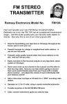
TELEVISION
TRANSMITTER KIT
Ramsey Electronics Model No.
TV6C
Don’t string cables through the house! Transmit your VCR or
camera signal to any nearby TV set with great audio and video
quality. You can be the program manager of your own Mini-TV
station!
Typical uses of the TV transmitter:
•
•
•
•
•
Watching one VCR from anywhere in the house
Using the camcorder camera to watch remote areas
Hidden camera fun
Home TV station
Student TV station
The Ramsey TV6C transmitter features:
•
•
•
•
•
Runs on 12 to 15 volts DC
On-board whip antenna
Stable output adjustable to channels 3 - 6
Clear, concise step-by-step instructions
Video and Audio inputs compatible with any VCR or TV camera
TV6C • 1
RAMSEY TRANSMITTER KITS
• FM10A, FM25B FM Stereo Transmitters
• The “Cube” Video Transmitters
• AM1, AM25 AM Transmitters
RAMSEY RECEIVER KITS
• FR1 FM Broadcast Receiver
• AR1 Aircraft Band Receiver
• SR2 Shortwave Receiver
• AA7 Active Antenna
• SC1 Shortwave Converter
RAMSEY HOBBY KITS
• SG7 Personal Speed Radar
• SS70A Speech Scrambler
• SP1 Speakerphone
• MD3 Microwave Motion Detector
• ECG1 Heart Monitor
• TFM3 Tri-Field Meter
RAMSEY AMATEUR RADIO KITS
• DDF1 Doppler Direction Finder
• HR Series HF All Mode Receivers
• QRP Series HF CW Transmitters
• CW7 CW Keyer
• CPO3 Code Practice Oscillator
• VLF1 Low Bander
• QRP Power Amplifiers
RAMSEY MINI-KITS
Many other kits are available for hobby, school, Scouts and just plain FUN.
New kits are always under development. Write or call for our free Ramsey
catalog.
TV6C TV TRANSMITTER KIT INSTRUCTION MANUAL
Ramsey Electronics publication No. MTV6C Revision 1.2a
First printing: January 1995
COPYRIGHT 1995 by Ramsey Electronics, Inc. 590 Fishers Station Drive, Victor, New York
14564. All rights reserved. No portion of this publication may be copied or duplicated without the
written permission of Ramsey Electronics, Inc. Printed in the United States of America.
TV6C • 2
Ramsey Publication No. MTV6C
Price $5.00
KIT ASSEMBLY
AND INSTRUCTION MANUAL FOR
TELEVISION
TRANSMITTER
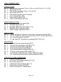
TABLE OF CONTENTS
Introduction to the TV6C ................ 4
Building your kit .............................. 4
Parts list.......................................... 5
TV6C Circuit description................. 6
Parts placement ............................. 8
TV6C assembly instructions........... 9
Testing, adjustments .................... 12
Troubleshooting guide.................. 14
Appendix A, FCC Rules ............... 15
Schematic diagram....................... 22
Ramsey kit warranty..................... 23
RAMSEY ELECTRONICS, INC.
590 Fishers Station Drive
Victor, New York 14564
Phone (585) 924-4560
Fax (585) 924-4555
www.ramseykits.com
TV6C • 3
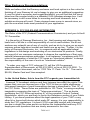
INTRODUCTION TO THE TV6C:
The answer to all your TV and VCR hook-up problems is now in your hands.
Your TV6C TV Transmitter kit is the handy "wireless wire" you can use to
connect up the whole house for TV of your choice!
The TV6C accepts normal video and audio signals from VCRs, camcorders, or
TV cameras and generates a low power TV signal that can be picked up by
nearby TV sets. Please be aware that this kit is a real transmitter and can be
received by others - whether they want to or not! Be especially cautious to not
cause any interference to neighbors or others close by, they are entitled to
enjoy their own choice of programming without any interference from you. Pay
particular attention to the FCC Rules section later in the manual.
In keeping with our spirit of getting folks to build and learn, you'll see that your
kit has step-by-step instructions that carefully guide you to a finished, fully
operating kit. And, you'll not only build the kit, but learn it too! Kit building is a
fun and rewarding way to spend an evening at home, especially on a cold
winter night.
BUILDING YOUR KIT:
Many Ramsey kits can be classified as single evening kits suitable for
beginners or old pros and this one is no exception. But, don't let confidence
get in the way of better judgment. With well over 100 solder joints, even being
right 99% of the time will still allow one error to creep in! Therefore, please
take to heart these following guidelines:
•
•
•
•
•
•
Use a comfortable soldering iron or pencil for assembly. 30 to 50
watts is ideal.
Keep your iron tip clean; it will then produce professional, shiny
and reliable joints. Use a damp sponge to wipe your tip before
every joint. Use the wife's kitchen sponge and not your expensive
super-dandy-whiz-bang car wash sponge!
Good lighting is a must; why strain yourself with poor lighting?
Take advantage of the fact that our manuals are written in stages,
take a break between sections and check your work before
proceeding on.
Be on the look-out after each solder joint for a splash, bridge or
errant wire lead that could prove hard to find later.
Enough said, let's get building....
TV6C • 4
TV6C PARTS LIST:
CAPACITORS
7 .001 uf disc (marked .001 or 102 or 1nf) [C3,4,5,6,11,14,15]
2 39 pf disc [C7,9]
1 100 pf disc (marked 100 or 101) [C10]
2 68 pf disc [C12,13]
1 220 pf disc [bottom of PC board]
1 2.2 uf electrolytic [C2]
1 100 uf electrolytic [C1]
2 1000 uf electrolytic [C8,16]
SEMICONDUCTORS
1 1N4148 or 1N914 diode [D1]
2 1N4002 diode [D2,3]
4 2N3904 NPN transistor [Q1,2,3,4]
1 2N3866 NPN transistor [Q5]
1 7808 voltage regulator [VR1]
INDUCTORS
1
.15 uh miniature inductor (has brown and green bands) [L5]
2
2.2 uh miniature inductor (green body with 2 red bands) [L2,3]
1
5.5 turn slug tuned coil [L4]
1
IF can style RF transformer (marked 42IF122) [L1]
RESISTORS
1 180 ohm (brown-gray-brown) [R1]
3
1K ohm (brown-black-red) [R1,2,11]
1
3K ohm (orange-black-red) [R4]
3
4.7K (yellow-violet-red) [R5,8]
2
10K (brown-black-orange) [R9,10]
2
75 ohm (violet-green-black) [R6,12]
1
1K trimmer potentiometer (yellow adjuster) [R7]
1
5K trimmer potentiometer (yellow adjuster) [R3]
CONTROLS AND HARDWARE
1 Pushbutton switch [S1]
3 PC mount RCA phono jacks [J1,2,3]
1 DC power jack [J4]
1 Telescopic whip antenna [Ant 1]
1 Printed circuit board [TV6C]
1 Plastic tuning tool “diddle stick”
TV6C • 5
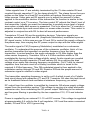
CIRCUIT DESCRIPTION:
Video signals from J1 are suitably terminated by the 75 ohm resistor R6 and
coupled through capacitor C1 to the clamp diode D1. The clamp forces the sync
pulses on the video to a fixed DC level which will reduce 'blooming' on some
video scenes. Video gain pot R3 permits you to adjust the amount of video
applied to the modulator section of the transmitter, its function is similar to the
contrast control on a TV receiver. The bias control R7 adjusts the 'black' level of
the transmitter. Ideally you want the transmitter to produce some level of signal
even when a totally dark screen is presented. This is to allow the TV receiver to
properly maintain sync and sound when no screen video is seen. This control is
adjusted in conjunction with R3 for best all-around performance.
Transistors Q1 and Q2 are the modulator devices. Television signals are
complex waveforms which are AM (Amplitude Modulation) modulated upon an
RF signal carrier. In this case we use Q1 and Q2 to control the supply voltage to
the power amp, thus varying the RF power output in step with the video signal.
The audio signal is FM (Frequency Modulation) modulated on a subcarrier
oscillator. To understand the purpose of the subcarrier oscillator, think of it as
another transmitter that operates on another frequency from the video
transmitter. In actual practice, the audio subcarrier is 4.5 Mhz higher than the
video carrier frequency. Transistor Q3 is a 4.5 Mhz oscillator which is FM
modulated by having its bias voltage slightly varied. Audio signals are coupled
into Q3's base through capacitor C2 and resistor R4, thus varying the bias
voltage at an audio rate causing frequency modulation. Coil L1 and its internal
capacitor form the tank circuit of a Hartley oscillator which is tuned to the
required 4.5 Mhz frequency. This FM modulated signal is then applied to the
modulator section through C5 and R9. Resistor R9 sets the proper amount of
subcarrier signal in relation to video signal.
The transmitter operating frequency is set by coil L4 which is part of a Colpitts
tank circuit along with capacitors C7 and C9. Transistor Q4 uses this tank circuit
as its feedback network and oscillates at whatever frequency you select.
RF output from the oscillator is amplified by transistor Q5 whose supply voltage
comes from the modulator section. This voltage is varying at a video and audio
subcarrier rate, thus modulating the RF power output. Matching to the antenna
and low pass filtering is provided by the two capacitors C12, C13 and inductor
L5.
Power is supplied by an external 12 -15 volt DC source. This voltage is regulated
at approximately 9.4 volts by the 8 volt regulator, VR1 and the series connected
diodes, D2 and D3 in VR1’s ground leg.
TV6C • 6
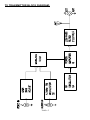
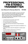
TV TRANSMITTER BLOCK DIAGRAM:
TV6C • 7
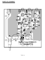
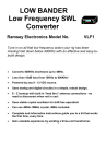
PARTS PLACEMENT:
TV6C • 8
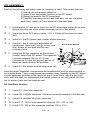
KIT ASSEMBLY:
Each of the following assembly steps is complete in itself. This means that you:
1) Identify the component called for,
2) Insert it into the proper location on the PC board,
3) Solder its leads to the PC board and,
4) Carefully trim away the excess lead wire. As you complete
each step, check it off and proceed to the next step.
1. Install switch S1 into its six holes on the PC board and solder all six pins.
Ignore the other set of six solder terminals on top of the switch.
2. Install the three RCA phono jacks, J1,2,3. Solder all four pins on each
jack.
3. Install J4, the DC power jack, solder all pins securely.
5. Install the 220 pf capacitor on the bottom
(solder) side of the PC board. The capacitor
connects between the pin of L1 that
connects to C4 and the ground lead of L1.
Keep the leads as short as possible.
BOTTOM OF BOARD
22
0
4. Install L1, the IF can style adjustable RF
transformer. Note that it will go in only one
way. Solder all five pins and the two
mounting tabs.
6. Install L4, the plastic molded slug tuned coil.
L1
Now the major 'landmark' components are installed and we'll go about putting in
the smaller parts. These components are spaced close together on the PC board,
so pay particular attention to the layout so you'll install them right the first time!
Also, we'll ask that you understand that install means to not only install the part,
but to solder it and trim the leads as well.
RF Oscillator Section
7. Install C7, 39 pf disc capacitor.
8. Install Q4, 2N3904 transistor. Observe correct placement of the flat side.
9. Install C9, another 39 pf disc capacitor.
10. Install C11, .001 uf disc capacitor (marked .001, 102, or 1nf).
11. Install C10, 100 pf disc capacitor (marked 100 or 101).
TV6C • 9
12. Install R10, 10K ohm (brown-black-orange).
13. Install L2, 2.2 uh inductor (green body marked with two red bands).
Modulator Section
14. Install C1, 100uf electrolytic capacitor. Electrolytic capacitors are
polarized devices with a plus (+) and a minus (-) lead. This means that
you must install them on your PC board in the correct direction, with the
plus lead going into the plus hole and the minus lead going into the
minus hole. Ordinarily, only the minus side is marked on the capacitor
body with a dark band and a clearly labeled (-) sign shown, with the
other lead being the plus (+) side. Note that the PC board layout diagram
shows where the plus side should go.
15. Install C15, .001 uf disc capacitor (marked .001, 102 or 1nf).
16. Install R1, 180 ohm (brown-gray-brown).
17. Install C6, .001 uf disc capacitor (marked .001, 102 or 1nf).
18. Install Q1 and Q2, 2N3904 transistors. Pay attention to correct placement
of their flat sides.
19. Install R8, 4.7K ohm (yellow-violet-red).
20. Install C5, .001 uf (marked .001, 102 or 1nf).
21. Install R9, 10K ohm (brown-black-orange).
22. Install L3, 2.2 uh inductor (green body marked with two red bands).
23. Install R7, the 1 K ohm trimmer pot. This is the small yellow device with
a screwdriver adjustment slot, marked 102. Be sure not to mix it up
with R7, the 5K pot (marked 502). Make sure it is firmly seated and
securely soldered to the PC board.
24. Install R3, the 5 K ohm trimmer pot. This is the other small yellow
device with an adjustment slot, however this one is marked 502. Make
sure it is firmly seated and securely soldered to the PC board.
25. Install D1, 1N4148 or 1N914 diode. Pay close attention to the proper
orientation of the banded end of the diode.
26. Install R6, 75 ohm (violet-green-black).
Audio subcarrier section
27. Install C2, 2.2 uf electrolytic capacitor, observe polarity.
TV6C • 10
28. Install C3, .001uf disc capacitor (marked .001, 102 or 1nf).
29. Install R5, 4.7K ohm (yellow-violet-red).
30. Install R4, 3K ohm (orange-brown-red)
31. Install C4, .001 uf disc capacitor (marked .001, 102 or 1nf).
32. Install Q3, 2N3904 transistor. Observe correct placement of the flat side.
33. Install R2, 1K ohm (brown-black-red).
34. Install Jumper JMP1. This is a short scrap of component lead wire bent
to fit into the PC board holes and soldered into place. Its function is to act
as a 'bridge' over circuit board traces running underneath it!
RF Power Amplifier and Power Supply Sections
35. Install R11, 1K ohm (brown-black-red).
36. Install Q5, 2N3866 transistor, Observe correct orientation of the small
metal locating tab on the transistor’s metal body. This transistor is rated
for higher power than the other devices, so it is housed in a metal
package able to dissipate more heat.
37. Install C12, 68 pf disc capacitor.
38. Install C13, 68 pf disc capacitor.
39. Install C14, .001 disc capacitor (marked .001, 102 or 1nf).
40. Install L5, .15 uh inductor (green body marked with brown and green
bands).
41. Install R12, 75 ohms (violet-green-black).
42. Install C8 and C16, 1000 uf electrolytic capacitors. Remember to
observe correct orientation of polarity.
43. Install D2 and D3, 1N4002 rectifier diodes (black epoxy body). Notice
that these devices stand upright rather than laying flat as most other
components. Be sure to observe correct orientation of their banded ends
which face C8.
44. Install VR1, 7808 voltage regulator. Pay attention to the proper
placement of the metal back side which should face diodes D2 and D3.
45. Now it is time not only to sit back and admire your work but to carefully
examine all solder joints and placement of components before the final
TV6C • 11
assembly is completed. Be sure all excess leads are trimmed away and
touch up any solder joints that don't appear perfect. You may wish to
brush the solder side of the PC board with a stiff brush to make sure
that no loose lead trimmings or solder drippings are lodged between
connections.
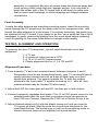
Final Assembly:
Locate the whip antenna and matching mounting screw. Insert the mounting
screw through the PC board from the solder side to the component side and
thread the whip antenna on to the screw. For a sturdy assembly, the screw may
be soldered to the PC board. If you desire to do this, use a small nail file or bit of
sandpaper to gently remove the plating from the screw head before soldering
since the plating on the screw head does not accept solder readily.
TESTING, ALIGNMENT AND OPERATION:
To properly test your TV transmitter, you will need these basic tools and
equipment:
1. A TV set,
2. A source of video such as a VCR,
3. A 12 to 15 volt DC power source,
4. Plastic alignment tool for L1, L4, R3 and R7.
Alignment Procedure:
1. Tune a nearby TV set to an unused channel between channels 3 and 6.
Remember since we are transmitting locally, your TV set should have a
nearby antenna connected such as a pair of rabbit ears or a short
dipole style antenna. You cannot operate the TV with the outdoor
antenna or the local cable TV system hooked up to it - after all, their
master antenna may be located 30 miles away!
2. Adjust both R3, the video gain pot and R7, the bias pot to mid rotation.
3. Connect a properly regulated and stable 12 to 15 volt DC power source to the
external power jack. Be sure that your power source can provide at
least 100 ma of current. Depress the TV6C on-off button to turn it on.
4. Adjust channel adjust coil L4 with the plastic tuning tool until you see the
TV screen go blank. Slightly move the slug around this point for the
most blank picture. The sound may or may not be producing noise or
silence since we have not yet adjusted our sound section.
TV6C • 12
5. Connect a VCR or other video and audio source to the corresponding inputs
on the TV transmitter. Insert a tape into your VCR and press 'Play'.
6. You should now see some resemblance of a picture on your TV screen.
Now adjust channel adjust coil L4 for best picture.
7. Adjust the video gain pot R3 for best 'brightness' in the picture and bias pot
R7 for best overall picture. These two adjustments interact and it is
best to 'fiddle' back and forth until best picture is obtained. You may
wish to touch-up the channel coil L4 also.
8. Adjust the audio subcarrier coil L1 for best sounding audio.
Using the TV6C within the home:
One of the most practical uses of the TV6C is to hook it up to your VCR and
transmit a tape to other TV sets throughout the house, yard or to the garage. This
connection involves using shielded audio or video 'patch cords' to connect the
audio and video outputs from the VCR to the TV transmitter inputs. These patch
cords are available at any Radio Shack or stereo shop, and don't believe that
you'll need the Ultra-Classic El-Mucho-Bucko gold plated, oxygen free type
either! Any good quality cable suitable for audio will pass your video just fine.
Remember, even if this is your only use of the TV transmitter, it is your
responsibility to ensure that your operation does not interfere with your neighbors
TV viewing - and don't forget, someone may be watching what you're watching
too!
Antenna considerations:
The TV6C's on-board whip antenna is suitable for most in-home applications and
can usually transmit throughout an average sized home. If you need more range,
an external antenna connected to the TV transmitter's antenna jack will do the
trick. Use a length of RG-59 or RG-58 coax cable to locate the antenna in a
position closer to the TV set when reception is desired. Under no circumstances
should you attempt to connect a larger antenna to the TV6C. FCC rules are very
strict as to radiated power allowed. In the interest of remaining invisible to others,
use a minimum amount of antenna system for reliable operation. Remember your
obligation is to not cause interference to others. Your neighbor may have
invested in a high gain TV antenna system and top quality TV set and doesn't
need you to come along to spoil it for him. If you desire to connect the TV6C
directly to a TV set, be sure that there are no other connections to the TV set’s
antenna terminals!
TV6C • 13
Troubleshooting Hints:
If your TV6C does not work at all, re-check the following:
•
•
•
•
•
•
Correct orientation of all transistor flat sides.
Correct resistor placement, "that's not a 10K where a 1K should be,
is it?"
Proper power source of 12 to 15 volts DC, check this by actually
measuring the power source’s voltage while it is connected and
powering your TV6C.
Proper video and audio from your source, be it a VCR or other.
Correct placement of disc capacitors. Make sure the .001 uf values
are not confused with other capacitors.
All solder connections.
As a general rule, frequency drift or hum in the audio is caused by a poorly
regulated power source and erratic or intermittent operation from faulty solder
joints or cable connections.
If you’re having trouble getting your TV6C to tune to channel 6 you may want
to try changing C7 and C9 to 27 pf capacitors. The change may affect your
ability to tune channel 3 but will move the range up so that you can tune
channel 6.
The Ramsey Electronics Case, Knob and Hardware Set:
Your finished TV transmitter can be installed in a variety of enclosures of your
own design and choosing. You might be planning to combine several Ramsey
kit circuit boards into one single enclosure. Ramsey offers an inexpensive, yet
attractive custom designed case and knob set that will give your unit that
finished look and increase its resale value. These sturdy black instrument
cases are supplied with neatly lettered front and rear panels that are already
punched and drilled for the controls and switches. Also included is any
necessary mounting hardware, matching knobs and even rubber feet. Most
Ramsey kits are available with this case option providing you with a complete
matching station look throughout your shop or home.
TV6C • 14
Other Enclosure Recommendations:
While we believe that the Ramsey enclosure and knob option is a fine value for
finishing off your Ramsey kit, we're happy to give you an additional suggestion.
If your first goal is economy and rugged portability, you will find that the circuit
board can be mounted nicely in a standard VHS videotape storage box. It will
be necessary to drill some holes for mounting and knob clearance, but a
suitable enclosure will result. These storage boxes come in several sizes, so
pick the one which looks most practical for your application.
APPENDIX A: FCC RULES AND INFORMATION
The Rules of the FCC (Federal Communications Commission) and your kit built
TV Transmitter.
It is the policy of Ramsey Electronics, Inc., that knowing and observing the
lawful use of all kits is a first responsibility of our kit user-builders. We do not
endorse any unlawful use of any of our kits, and we do try to give you as much
common sense help about normal and lawful use as we can. Further, it is the
policy of Ramsey Electronics, Inc., to cooperate with all applicable federal
regulations in the design and marketing of our electronics kit products. Finally,
we urge all of our overseas customers to observe the regulations of their own
national telecommunications authorities. In all instances, compliance with FCC
rules in the operation of what the FCC terms an "intentional radiator" is always
the responsibility of the user of such an "intentional radiator".
To order your copy of FCC rules part 15, call the US Government,
Superintendent of Documents, at 202-512-3238, or fax at 202-512-2250. To
order the correct document, ask for “CFR Title 17: Parts 1 to 19.” The cost is
$24.00, Master Card and Visa accepted.
In the United States, this is how the FCC regards your transmitter kit:
Licensed TV broadcast stations and their listeners have ALL the rights! This
means that your non-licensed use of the TV6C kit has no rights whatsoever.
Unlicensed operation of small transmitting devices is discussed in "Part 15" of
the FCC Rules. These Rules are published in 100 "Parts," covering everything
imaginable concerning the topic of "Telecommunications." The six books
containing the FCC Rules are section 47 of the complete Code of Federal
Regulations, which you are likely to find in the Reference section of your Public
Library. If you have questions about the legal operation of your TV6C or any
other kit or home-built device which emits RF energy, it is your responsibility to
study the FCC regulations. It is best if YOU read (and consult with a lawyer if
you are in doubt) the rules and do not bother the understaffed and busy FCC
employees with questions that are clearly answered in the rules.
TV6C • 15
Here are the primary "dos and don'ts" picked from the current FCC Rules, as
of May, 1990. This is only a brief look at the rules and should not be
construed to be the absolute complete legal interpretation! It is up to you to
operate within the proper FCC rules and Ramsey Electronics, Inc. cannot be
held responsible for any violation thereof.
1. Part 15 discusses various transmitters such as "wireless microphones" (for
example, the Ramsey FM-1, FM-4, etc.), cordless telephones and the like. In
general, the FCC permits various unlicensed transmitters provided that they DO
NOT cause ANY interference to authorized users. The FCC appears to
recognize the “wireless” ways of the world and allows such transmitters as long
as interference is not caused. Specific rules and electrical limits have been
written to assure this.
2. It is the sole responsibility of the builder-user of any TV or FM broadcastband device to research and fully avoid any and all interference to licensed
broadcast transmission and reception. This instruction manual gives you
practical advice on how to do a good job of finding a clear frequency, if one is
available.
3. For some frequency bands, the FCC sets 100 milliwatts (0.1 watt) as the
maximum permitted power output for unlicensed, home-built transmitting
devices, and that the combined length of your antenna and feedline (coaxial
cable or other) must not exceed 10 feet. The technical standards for the VHF
and UHF frequency bands are very different, primarily concerned with band
width and RF field strength.
4. FCC Rule 15.5: General conditions of operation: "(b) Operation...is subject
to the conditions that no harmful interference is caused and that interference
must be accepted that may be caused by the operation of an authorized radio
station, by another intentional or unintentional radiator, by industrial, scientific
and medical equipment, or by an incidental radiator. (c) The operator of a radio
frequency device shall be required to cease operating the device upon
notification by a Commission representative that the device is causing harmful
interference."
5. The most specific FCC regulation of unlicensed operation is that the "field
strength" of the signal must not exceed 100 microvolts/meter at a distance of 3
meters from the transmitter (FCC rule 15.209). If you have any concern about
this emission limit, have your device checked by a technician with accurate
measuring equipment. Remember that the "field strength" of a signal is
determined as much by the antenna as by the RF output of the transmitter
itself.
TV6C • 16
APPENDIX B: UNDERSTANDING LEGAL "FIELD STRENGTH"
A "microvolt" is one-millionth of one volt and designated "µV" in the following
explanations.
The new FCC Part 15 Rules specify a maximum "Field Strength" of your
transmitted signal. Since it is unlikely that you have the equipment to carry out
accurate field strength measurements in microvolts, it is useful to understand at
least the theory of field strength so that you can understand both what you can
expect from such transmitters, and what limits the FCC intends.
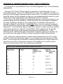
In all cases, the field strength of a signal decreases in direct proportion to the
distance away from the antenna. Power decreases by the square of distance:
for every doubling in distance, the signal power is quartered, but the field
strength voltage is only halved. Using this theory, we can construct a simple
chart to show the maximum permitted performance of a non-licensed FM band
transmitter. The theoretical figures assume a simple 1 meter receiving antenna
in all cases and do not take into consideration that reception can be greatly
enhanced with larger, multi-element antennas and preamplifiers. In the
following chart, the field strength (theoretical minimum) gets even stronger as
you move from the edge of these circular boundaries toward the antenna:
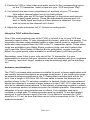
This "exercise in meters and microvolts" demonstrates that the FCC clearly
intends to limit the theoretical range of non-licensed devices operating in this
band. It also shows the potential for causing interference at a home down the
street from you. But it also shows that you can legally put out quite a good
signal over wider areas than you might have imagined.
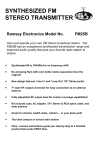
DISTANCE FROM TRANSMITTER ANTENNA
METERS
FEET
FIELD
STRENGTH
(µV)
TOTAL
RECEPTION
AREA
3
10
100
314 FT
6
20
50
1256 FT
12
39
25
4800 FT
24
78
12
19113 FT
48
157
6
1.8 ACRES
96
315
3
7.2 ACRES
TV6C • 17
For other kinds of radio services, the FCC restricts such factors as transmitter
power or antenna height, which cannot really limit the possible "range" of a
transmission under good conditions. By restricting the maximum field strength
at a specific distance from your antenna, the FCC clearly plans for your signal
to "die out" at a specific distance from your antenna, no matter what kind of
transmitter power or extra-gain antenna you are using. On the other hand, the
FCC standards do make it legal and possible for you to broadcast in a school
room or home - as long as you do not cause interference to broadcast
reception.
“Why talk about acres"?
There are three reasons to translate our look at "field strength" into "acres".
(1) The first one is easy: the numbers would get too cumbersome if we
discussed your possible signal coverage in terms of square feet or square
meters.
(2) It's easy to see that your signal can easily serve a school or home.
(3) And, if we remember that typical urban single-family home sites run
from 1/4 to 1/2 acre on the average, it should become extremely clear
that your obligation to avoid interfering with broadcast reception can
easily involve lots of homes, before adding apartments!
In fact, the most significant distance in the above chart is the 3 µV signal
strength permissible at 315 feet, covering a circular area of about 7.2 acres. A
quick check at a TV set’s specifications shows maximum sensitivity of about 5
µV before considering high-gain antennas or preamplifiers. Your non-licensed
signal can provide serious competition to a public broadcast station fifty miles
away, a station which someone in your neighborhood may have set up a
special antenna to enjoy.
Calibrated "field strength meters" such as described in the ARRL Radio
Amateur's Handbook can detect signals down to about 100 microvolts. To
measure RF field strength below such a level, professional or laboratory
equipment and sensitive receivers are required. A "sensitive" receiver
responds to a signal of 1 or even .5 microvolt "delivered" to the receiver input by
antenna. If the antenna is not good, the receiver cannot respond to the
presence of fractions of a microvolt of RF energy.
TV6C • 18
SUMMARY
The present edition of Part 15 of the FCC rules provides detailed guidance on
all aspects of using low-power transmitters. The main point is that you may not
cause any interference whatsoever to licensed broadcast services and that you
must be willing to put up with any interference that you may experience.
In addition to operations not requiring authorization, you also have the option
of writing a clear and polite letter to the FCC Engineer-in-Charge of your local
district, describing your intended operation. Mention the operating frequency
and planned hours of operation. This could be a good step to take if your
project is on behalf of a school, Scout or community group.
USAGE SUGGESTIONS FOR THE TV6C
1. Build and adjust this kit strictly according to the published instructions.
2. Use the whip antenna supplied with the kit.
3. Do not modify your kit in any way.
4. Check your intended operating frequency very carefully, as clearly
explained in this instruction manual, to ensure you will not cause
interference to reception of licensed broadcasting.
5. If you receive ANY complaint about your transmissions interfering
with broadcast reception, stop or change your operation
IMMEDIATELY.
6. If you are contacted by the FCC regarding use of this device,
cooperate fully and promptly.
7. Do your own homework and research to understand and comply with
present and future FCC rulings concerning devices of this kind.
8. Identify the location and purpose of your transmissions from time to
time. This is common courtesy toward other persons who may hear your
signal. The FCC is toughest about clandestine transmission which cost
time and money to track down.
9. Do not assume that the mere fact that you purchased this kit gives
you any specific right to use it for any purpose beyond generating a lowlevel RF signal which is barely detectable beyond the perimeter of your
personal dwelling space.
TV6C • 19
Finally, the FCC Rules call for the posting of printed notices on devices
intended for non-licensed operation under Part 15 Rules. You will find such
notices written up for the front or back of the instruction manual for nearly any
computer or video accessory that you have seen in recent months. Consult the
Part 15 Rules for the exact wording of such notices. Following is a text for such
a notice which responds to FCC rule making intentions:
NOTICE:
The radio-frequency "intentional radiator" device which may be constructed
from kit parts supplied by us is intended and designed by Ramsey Electronics,
Inc. to conform to applicable provisions of Part 15 of FCC Rules. The individual
kit-builder and all users of this device assume responsibility for lawful uses
conforming to FCC Part 15 Rules. Operation is subject to the following two
conditions:
[1] This device may not cause harmful interference, and
[2] this device must accept any interference received, including interference that
may cause undesired operation.
CASE UP INSTRUCTIONS:
The enclosure is a key element to the overall pride you will have upon
completing your Ramsey kit. The enclosure will show how you were able to
“build from scratch” a commercial piece of high-tech electronics. For some of
us, the enclosure will also hide a number of “not-so-pretty” assembly mistakes.
Once the kit is enclosed your friends will never know that you were new to
soldering. Finally, the enclosure case will protect your electronics from many
possible causes of damage so that you can receive years worth of enjoyment
using, talking about, and remembering the fun you had building your kit.
If you haven’t already done so, screw the antenna to the PC board. If you
wish you can solder the screw holding the antenna to the bottom of the
board so that you can unscrew the antenna with the cover on the unit and
screw it back in without removing the top cover. This is helpful if you intend
to transport your kit.
Note that the top cover has a groove and a lip on it that correspond to the
groove and lip on the bottom case half. Because the antenna has to fit
through the predrilled hole in the top of the case you’ll have to fit the case
halves together to determine which end is the front and which is the back
based on the antenna hole.
Once you’ve decided which end is the front, take the prepunched front
panel and slide it into the grooves in the bottom case half.
Insert the board into the case with the power switch, etc. extending through
the hole(s) in the front panel. Don’t screw the board into place yet.
Raise the rear portion of the PC board and extend the jacks through the
TV6C • 20
rear plastic plate. Insert the plate into the grooves on the base tray.
With both the front and rear panels in place, secure the PC board to the
bottom base tray with 4 short Phillips screws.
Place any knob or button covers on the switches and pots on the front panel.
Fit the top cover on and use the two long screws to hold it in place.
While the kit is flipped over, stick the rubber feet on the 4 corners of the case
bottom.
Now you’re really finished! Start using and amazing your friends with your new
TV Transmitter!
Final comment
A well-informed person will see today's FCC Rules to be evolving and
progressively less-restrictive. Even though today's technology is far more
complex than what was possible at the time of the Communications Act of 1934,
the FCC rules are becoming more relaxed, giving radio experimenters more and
more opportunities to explore many frequency bands, using many
communications modes, with no need for a formal license of any kind. A
thorough study of Part 15 of the FCC Rules, which is completely beyond the
purpose of this kit manual, will show you many legal uses of radio transmitting
devices which do not require licensing, either amateur or commercial.
To provide more personal and club radio-learning opportunities, and to cut
down on administrative costs, today's FCC permits far more non-licensed activity
than at any time in previous history. On the other hand, today's FCC
enforcement actions get bigger fines and real prison terms for scofflaws! From
CB (now 3 bands of it, for varying applications) to easy entry-level Amateur Radio
with long-term licensing, to numerous unlicensed Part 15 operations, the FCC is
beginning to look out for the interest and good plans and intentions of private
citizens and school-community groups as never before in radio communications
history. Learn the rules...observe them...and have fun in radio!
If you enjoyed this Ramsey kit, there're plenty more to choose from in our
catalog - write or call today!
TV6C • 21
TV6C • 22
The Ramsey Kit Warranty
Please read carefully BEFORE calling or writing in about your kit. Most problems can be
solved without contacting the factory.
Notice that this is not a "fine print" warranty. We want you to understand your rights and ours too! All
Ramsey kits will work if assembled properly. The very fact that your kit includes this new manual is your
assurance that a team of knowledgeable people have field-tested several "copies" of this kit straight from
the Ramsey Inventory. If you need help, please read through your manual carefully, all information
required to properly build and test your kit is contained within the pages!
1. DEFECTIVE PARTS: It's always easy to blame a part for a problem in your kit, Before you conclude
that a part may be bad, thoroughly check your work. Today's semiconductors and passive components
have reached incredibly high reliability levels, and it’s sad to say that our human construction skills have
not! But on rare occasions a sour component can slip through. All our kit parts carry the Ramsey
Electronics Warranty that they are free from defects for a full ninety (90) days from the date of purchase.
Defective parts will be replaced promptly at our expense. If you suspect any part to be defective, please
mail it to our factory for testing and replacement. Please send only the defective part(s), not the entire kit.
The part(s) MUST be returned to us in suitable condition for testing. Please be aware that testing can
usually determine if the part was truly defective or damaged by assembly or usage. Don't be afraid of
telling us that you 'blew-it', we're all human and in most cases, replacement parts are very reasonably
priced.
2. MISSING PARTS: Before assuming a part value is incorrect, check the parts listing carefully to see if it
is a critical value such as a specific coil or IC, or whether a RANGE of values is suitable (such as "100 to
500 uF"). Often times, common sense will solve a mysterious missing part problem. If you're missing five
10K ohm resistors and received five extra 1K resistors, you can pretty much be assured that the '1K ohm'
resistors are actually the 'missing' 10 K parts ("Hum-m-m, I guess the 'red' band really does look orange!")
Ramsey Electronics project kits are packed with pride in the USA. If you believe we packed an incorrect
part or omitted a part clearly indicated in your assembly manual as supplied with the basic kit by Ramsey,
please write or call us with information on the part you need and proof of kit purchase
3. FACTORY REPAIR OF ASSEMBLED KITS:
To qualify for Ramsey Electronics factory repair, kits MUST:
1. NOT be assembled with acid core solder or flux.
2. NOT be modified in any manner.
3. BE returned in fully-assembled form, not partially assembled.
4. BE accompanied by the proper repair fee. No repair will be undertaken until we have received the
MINIMUM repair fee (1 /2 hour labor) of $25.00, or authorization to charge it to your credit card
account.
5. INCLUDE a description of the problem and legible return address. DO NOT send a separate letter;
include all correspondence with the unit. Please do not include your own hardware such as
non-Ramsey cabinets, knobs, cables, external battery packs and the like. Ramsey Electronics,
Inc., reserves the right to refuse repair on ANY item in which we find excessive problems or
damage due to construction methods. To assist customers in such situations, Ramsey
Electronics, Inc., reserves the right to solve their needs on a case-by-case basis.
The repair is $50.00 per hour, regardless of the cost of the kit. Please understand that our technicians are
not volunteers and that set-up, testing, diagnosis, repair and repacking and paperwork can take nearly an
hour of paid employee time on even a simple kit. Of course, if we find that a part was defective in
manufacture, there will be no charge to repair your kit (But please realize that our technicians know the
difference between a defective part and parts burned out or damaged through improper use or assembly).
4. REFUNDS: You are given ten (10) days to examine our products. If you are not satisfied, you may
return your unassembled kit with all the parts and instructions and proof of purchase to the factory for a full
refund. The return package should be packed securely. Insurance is recommended. Please do not cause
needless delays, read all information carefully.
TV6C • 23
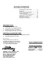
TELEVISION TRANSMITTER
Quick Reference Page Guide
Introduction to the TV6C ................ 4
Parts list ......................................... 5
TV6C Circuit description ................ 6
Parts placement ............................. 8
TV6C assembly instructions .......... 9
Appendix A, FCC Rules ............... 15
Schematic diagram ...................... 22
Ramsey kit warranty..................... 23
REQUIRED TOOLS
• Soldering Iron (WLC100)
• Thin Rosin Core Solder (RTS12)
• Needle Nose Pliers (PTS401)
• Small Diagonal Cutters (PTS400)
ADDITIONAL SUGGESTED ITEMS
Helping Hands Holder for PC Board/Parts (HH3)
Desoldering Braid (RTS08)
•
•
Price: $5.00
Ramsey Publication No. MTV6C
Assembly and Instruction manual for:
RAMSEY MODEL NO. TV6C
TV TRANSMITTER KIT
TOTAL SOLDER POINTS
109
ESTIMATED ASSEMBLY
TIME
Beginner ...............3.0 hrs
Intermediate .........1.75 hrs
Advanced .............1.3 hrs
RAMSEY ELECTRONICS, INC.
590 Fishers Station Drive
Victor, New York 14564
Phone (585) 924-4560
Fax (585) 924-4555
www.ramseykits.com
TV6C • 24