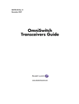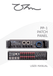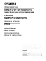
1
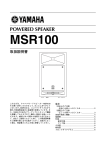
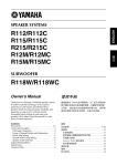
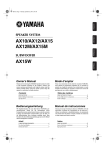
SPEAKER SYSTEMS
S112IVN/S115IVN/S215IVN
SM10IVN/SM12IVN/SM15IVN
SUBWOOFER
SW118IVN/SW215IVN
CROSSOVER NETWORK
PN90
Owner’s Manual
Mode d’emploi
Bedienungsanleitung
Manual de instrucciónes
Thank you for purchasing a YAMAHA product. To obtain
maximum performance from your YAMAHA speaker system
and ensure many years of trouble-free operation, we recommend
that you read this Owner’s Manual thoroughly before use.
Contents
Precautions ...................................................................... 2
Connecting the Speakers ................................................ 4
Specifications ................................................................... 6
Technical Data ...............................................................25
Precautions
AVOID EXCESSIVE HEAT, HUMIDITY, DUST AND VIBRATION
MAKE SURE THE POWER IS OFF BEFORE MAKING
OR REMOVING CONNECTIONS
When choosing a location for your speakers, avoid the fol-
Always turn the power switches of system components
lowing:
OFF prior to connecting or disconnecting cables. Failure to
do so may result in damage to speakers as well as to connected equipment.
• Direct sunlight, high temperatures (such as near heaters), or excessively low temperatures.
• High humidity.
DISCONNECT CABLES BEFORE MOVING THE SYS-
• Areas subject to excessive dust accumulation and vibration.
TEM
To prevent short circuits or breakage of cables, always disconnect cables prior to moving system equipment.
• Non-level or unstable surfaces.
HOW TO POWER UP YOUR SOUND SYSTEM
MATCH CONNECTOR POLARITY
To avoid damage to your speakers and other parts of your
system, when you turn on your system, ALWAYS turn the
When using two or more speaker systems, be sure match
the polarity (+/–) of the speaker system connectors to those
at the amplifier. If the polarities do not match, the sounds
power amp on last! This will avoid loud, damaging pops
that will annoy your audience, and blow your speakers.
When you power down, the amplifier should ALWAYS be
produced by the speakers will interfere with each other,
making it impossible to achieve a well-balanced sound
turned off first to avoid the same problems.
field.
KEEP THIS OWNER’S MANUAL IN A SAFE PLACE
FOR FUTURE REFERENCE
To protect your speakers
When choosing a power amplifier to use with your
speakers, make sure that its power output matches the
speakers’ power capacity (refer to the Specifications on
Poly Switch
All full-range loudspeakers are fitted with a self-resetting poly switch that protects the high-frequency driver
from damage caused by excessive power.
page 6). Even if the amplifier’s power output is lower
than the speakers’ PGM (program) power capacity, the
speakers may be damaged when clipping of a high input
signal occurs.
If a loudspeaker cabinet loses high-frequency output,
immediately remove power from the unit and wait for
two to three minutes. They should allow the poly switch
The following may cause damage to speakers:
• Feedback caused when using a microphone.
• Continuous high sound pressure level produced by
electronic instruments.
to reset. Re-apply power and check the performance of
the high-frequency driver before continuing with the
power reduced to a level that does not cause the poly
• Continuous high-power output distorted signals.
switch to interrupt the signal.
• Popping noises caused by turning on equipment, or
by connecting or disconnecting system components
On the SW118IVN/SW215IVN sub woofer, the Poly
Switch protects the woofer and a similar routine should
be followed if its output is lost.
while the amplifier is turned on.
–2–
This product, when used in combination
with amplification and/or additional
loudspeakers, may be capable of producing sound levels that could cause permanent hearing loss.
DO NOT operate at high volume levels
or at a level that is uncomfortable. If you
experience any discomfort or ringing in
the ears, or suspect an hearing loss, you
should consult an audiologist.
CAUTION!
For the five models, S112IVN, S115IVN, SM10IVN,
SM12IVN, and SM15IVN, use the TS-30, TS-40, TS-80,
or TS-90 speaker stand by Ultimate Support System, Inc.
sold separately.
When using speaker stands, observe the following precautions to prevent the speaker stands from falling over or the
speaker system being dropped.
• Use the speaker stands with their legs fully opened.
• Do not place more than one speaker on the same speaker
stand.
• Tighten fastening screws securely.
• Remove the speakers from the stands before moving the
stands or adjusting their height.
• Implement measures to prevent the speaker stands from
falling over.
• Use the TS-30, TS-40 at no higher than 130 cm for the
S112IVN, SM10IVN, SM12IVN and at no higher than
120 cm for the S115IVN and SM15IVN.
• Use the TS-80 and TS-90 at no higher than 140 cm for
all speaker models.
• The top tube of the TS-30 and TS-40 speaker stands has
a diameter of 1-1/2", but is tapered to 1-3/8" at the top to
fit in the mounting holes on the five models named. If
you should remove the top tube from a stand, be sure to
insert it with the narrow end up when reassembling.
The SW118IVN, SW215IVN subwoofer has a metal socket
to allow mounting of a satellite speaker. Do not use a pole
longer than 56". Use a pole with an outer diameter of 1-3/
8".
SPEAKER HANDLES
The handles on your speakers are for transportation. They
are not designed for suspension or hanging.
–3–
Connecting the Speakers
CONNECTION EXAMPLE 1
The illustration below shows audio connections for a standard setup using two speaker systems.
DAISY-CHAINED
MIXING
CONSOLE
GRAPHIC
EQUALIZER
L
POWER
AMPLIFIER
L
L
SPEAKER
SYSTEMS
R
SPEAKER
SYSTEMS
R
R
Daisy-Chaining Speakers
Since the speaker systems in this series are equipped with two input terminals that are internally connected in parallel, it is
possible “daisy-chain” speakers by connecting the output from the power amplifier to one Neutrik connector, and a second
speaker system to the other.
We do not recommend connecting more than two 8 speakers in parallel. Two parallel-connected 8 speakers have a total
impedance of 4 , which is the minimum that should be connected to one amplifier output channel. The S112IVN, S115IVN,
SM10IVN, SM12IVN, SM15IVN and SW118IVN are 8 speakers, and two of these can safely be paralleled on one output. The
S215IVN and SW215IVN, however, have an impedance of 4 and should not be parallel-connected with another S215IVN /
SW215IVN or any other model.
Neutrik NL4FC Plug Wiring
If you will be using the Neutrik connectors for speaker input, wire the plugs as shown below. Be sure to use proper speaker
cable—NOT shielded instrument or line cable—for all speaker connections.
2– (NO USE)
2+ (NO USE)
1+ : HOT(+)
1– :COLD (–)
Neutrik NL4FC connector
Caution: Use only unshielded speaker cable with stranded conductors to connect speakers to the speaker terminals on a power
amplifier. The use of audio cable not rated as sufficient for the amplifier’s maximum output level can create a potential fire
hazard.
–4–
CONNECTION EXAMPLE 2
This example shows audio connections for a system using SW118IVN or SW215IVN Subwoofers and a PN90 Crossover Network.
TWO-CHANNEL
POWER AMPLIFIER
SPEAKER
SYSTEM
PN90
L
L
LEFT
MIXING
CONSOLE
TWO-CHANNEL
GRAPHIC
EQUALIZER
HIGH
INPUT
OUTPUT
SW118IVN
or
SW215IVN
RIGHT
L
L
R
R
L
L
LEFT
INPUTS
TO POWER
AMP INPUTS
RIGHT
R
R
LEFT
LOW
INPUT
OUTPUT
SPEAKER
SYSTEM
RIGHT
R
R
TWO-CHANNEL
POWER AMPLIFIER
SW118IVN
or
SW215IVN
• Do not connect the PN90 between the power amplifiers and the SW118IVN, SW215IVN subwoofers, as doing so will damage
the equipment.
• Although the PN90 has a standard load impedance of 15 k , it can be used with loads between 7.5 and 30 k , allowing use
with most power amplifiers.
• Since the LOW signal polarity is inverted at the crossover point between the LOW and HIGH signals, be sure to reverse the
polarity when connecting the SW118IVN, SW215IVN input connectors to the power amplifier output connectors.
This polarity correction must not be made by reversing the polarity of the connections between the PN90 and the power
amplifiers, as doing so will damage the equipment. Please reverse the polarity between the power amplifiers and the
SW118IVNs, SW215IVNs.
• The PN90 uses unbalanced connectors. Use shielded audio cable with high-quality phone plugs to connect the PN90.
The balance between the LOW and HIGH signal levels may be adjusted using the power amplifier volume controls. A good
starting point is generally achieved for typical sound sources by raising the LOW signal level about 8 dB higher than that of the
HIGH signal.
–5–
Specifications
Model
SM10IVN
Enclosure
Speaker Unit LF
10" cone
HF
1" driver
12" cone
15" cone
15" cone x 2
2" driver
60 Hz to 16 kHz
150 W
55 Hz to 16 kHz
250 W
42 Hz to 16 kHz
500 W
200 W
400 W
300 W
600 W
500 W
1000 W
1000 W
2000 W
95 dB SPL (1W, 1m)
60˚
97 dB SPL (1W, 1m)
Nominal Impedance
8
Horizontal
Dispersion
Vertical
Crossover Frequency
4
99 dB SPL (1W, 1m)
90˚
40˚
1.8 kHz
2 kHz
Input Connectors
1.7 kHz
1.5 kHz
Neutrik NL4MP x 2 (parallel input)
Dimensions (W x H x D)
560 x 339 x 277 mm
Weight
12.2 kg
S112IVN: 400 x 638 x 318 mm
SM12IVN: 643 x 402 x 344 mm
S115IVN: 475 x 712 x 362 mm
SM15IVN: 720 x 485 x 345 mm
S112IVN: 19.3 kg,
SM12IVN: 19.5 kg,
S115IVN: 27.5 kg,
SM15IVN: 26 kg
S112IVN, S115IVN
75˚
S215IVN
70 Hz to 20 kHz
100 W
PGM
MAX
Sensitivity
Nominal
S115IVN/SM15IVN
Bass reflex type
Frequency Response
Power
NOISE*
Capacity
S112IVN/SM12IVN
S215IVN
105˚
500 x 1170 x 600 mm
46 kg
SM10IVN, SM12IVN, SM15IVN
102.5˚
77.5˚
120˚
H
H
30˚
H
D
W
D
D
W
W
Model
Crossover Frequency
Model
Enclosure
Speaker Unit
SW215IVN
Bass reflex type
18" cone
15" cone x 2
Frequency Response
Power Capacity
SW118IVN
Recommended Load Impedance
Insertion loss
30 Hz to 2 kHz
33 Hz to 2 kHz
NOISE*
PGM
250 W
500 W
500 W
1000 W
MAX
1000 W
8
2000 W
4
96 dB SPL (1W, 1m)
98 dB SPL (1W, 1m)
Nominal Impedance
Sensitivity
Recommended Crossover Frequency
Input Connectors
PN90
90 Hz, 12 dB/octave
(at 15 k load)
15 k
3 dB
Input Connectors
Output Connectors
Dimensions (W x H x D)
Weight
1/4" phone jack x 2
1/4" phone jack x 4
227 x 38 x 76 mm
0.6 kg
PN90
6.2
90 Hz, 12 dB/octave
Neutrik NL4MP x 2 (parallel input)
Dimensions (W x H x D)
Weight
542 x 654 x 791 mm
32.4 kg
SW118IVN
1115 x 520 x 600 mm
63.5 kg
216
W
SW215IVN
H
H
D
D
W
63.5
H
Unit: mm
✻ : EIA RS-426
Specifications subject to change
without notice
W
–6–
D
Technical Data / Données techniques
Technische Daten / Datos técnicos
Frequency Response / Impedance
Réponse en fréquence/impédance
Frequenzgang/Impedanz
Respuesta en frecuencia/Impedancia
• SM10 IVN
• S115IVN/SM15 IVN
100
100
RESPONSE(dB)
110
90
80
16
70
60
4
100
1k
80
16
70
8
20
90
60
10k
8
4
20
100
FREQUENCY(Hz)
• S215IVN
100
100
90
80
16
70
RESPONSE(dB)
110
RESPONSE(dB)
110
90
8
70
4
100
1k
16
80
8
20
60
10k
4
2
20
100
FREQUENCY(Hz)
100
100
90
80
16
70
RESPONSE(dB)
110
RESPONSE(dB)
10k
• SW215IVN
110
4
100
1k
90
16
80
8
70
8
20
1k
FREQUENCY(Hz)
• SW118IVN
60
10k
FREQUENCY(Hz)
• S112IVN/SM12IVN
60
1k
60
10k
FREQUENCY(Hz)
4
2
20
100
1k
FREQUENCY(Hz)
– 25 –
10k
Additions
RESPONSE(dB)
110
Horizontal Directivity / Directivité horizontale
Abstrahlung horizontal / Directividad horizontal
• SM10 IVN
40
50
270°
40
12
0°
10
0
10
0
10
0
0
10
0
10
0
10
21
0°
20
30
40
30
40
30
40
180°
180°
15
21
0°
20
0°
24
0°
0°
24
30
0°
30
15
20
12
0°
10
50
90°
0
50
90°
°
0
60
10
°
20
30
0°
60
30
30
°
40
0°
33
50
270°
• 4kHz
• 8kHz
• 16kHz
30
°
30
0°
0°
0°
0°
33
• 500Hz
• 1kHz
• 2kHz
• S112IVN/SM12IVN
20
30
40
50
270°
40
12
0°
20
20
0°
24
0°
15
180°
180°
21
0°
15
21
0°
0°
0°
24
30
12
0°
10
50
90°
0
50
90°
°
0
60
10
°
20
30
0°
60
30
30
°
40
0°
33
50
270°
• 4kHz
• 8kHz
• 16kHz
30
°
30
0°
0°
0°
0°
33
• 500Hz
• 1kHz
• 2kHz
• S115IVN/SM15IVN
0°
30
40
50
270°
12
0°
30
20
20
0°
24
0°
15
180°
180°
21
0°
15
21
0°
0°
0°
24
40
12
0°
20
50
90°
10
50
90°
°
0
60
0
°
10
30
0°
60
20
30
°
30
0°
40
0°
33
30
0°
50
270°
• 4kHz
• 8kHz
• 16kHz
30
°
0°
33
• 500Hz
• 1kHz
• 2kHz
• S215IVN
40
50
270°
12
0°
20
10
0
0
21
0°
180°
180°
15
21
0°
30
10
20
0°
24
0°
0°
24
40
0°
30
15
20
– 26 –
30
40
12
0°
10
50
90°
0
50
90°
°
0
60
10
°
20
30
0°
60
30
30
°
40
0°
33
50
270°
• 4kHz
• 8kHz
• 16kHz
30
°
30
0°
0°
0°
0°
33
• 500Hz
• 1kHz
• 2kHz
Vertical Directivity / Directivité verticale
Vertikale Richtcharkteristik / Directividad vertical
• SM10 IVN
40
50
270°
12
0°
30
10
0
10
0
10
0
0
10
0
10
0
10
21
0°
20
30
40
30
40
30
40
180°
180°
15
21
0°
20
0°
24
0°
0°
24
40
0°
30
15
20
12
0°
10
50
90°
0
50
90°
°
0
60
10
°
20
30
0°
60
30
30
°
40
0°
33
50
270°
• 4kHz
• 8kHz
• 16kHz
30
°
30
0°
0°
0°
0°
33
• 500Hz
• 1kHz
• 2kHz
• S112IVN/SM12IVN
20
30
40
50
270°
12
0°
30
20
0°
180°
180°
15
21
0°
15
21
0°
20
0°
24
0°
0°
24
40
12
0°
10
50
90°
0
50
90°
°
0
60
10
°
20
30
0°
60
30
30
°
40
0°
33
50
270°
• 4kHz
• 8kHz
• 16kHz
30
°
30
0°
0°
0°
0°
33
• 500Hz
• 1kHz
• 2kHz
• S115IVN/SM15IVN
50
270°
12
0°
30
21
0°
20
180°
180°
15
21
0°
20
0°
24
0°
0°
24
40
• S215IVN
40
50
270°
12
0°
20
10
0
0
21
0°
180°
180°
15
21
0°
30
10
20
0°
24
0°
0°
24
40
0°
30
15
20
– 27 –
30
40
12
0°
10
50
90°
0
50
90°
°
0
60
10
°
20
30
0°
60
30
30
°
40
0°
33
50
270°
• 4kHz
• 8kHz
• 16kHz
30
°
30
0°
0°
0°
0°
33
• 500Hz
• 1kHz
• 2kHz
Additions
40
0°
30
15
20
12
0°
10
50
90°
0
50
90°
°
0
60
10
°
20
30
0°
60
30
30
°
40
0°
33
50
270°
• 4kHz
• 8kHz
• 16kHz
30
°
30
0°
0°
0°
0°
33
• 500Hz
• 1kHz
• 2kHz
Yamaha Manual Library
http://www2.yamaha.co.jp/manual/english/
M.D.G., Pro Audio & Digital Musical Instrument Division, Yamaha Corporation
© 2002 Yamaha Corporation
CJY0333 209AP A0
Printed in Taiwan