1
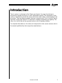
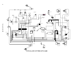
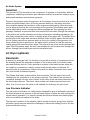
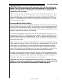
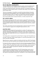
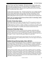
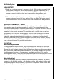
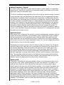
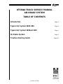
OTTAWA TRUCK SERVICE MANUAL
AIR BRAKE SYSTEM
TABLE OF CONTENTS
Introduction
Page 3
Typical Air System With ABS
Page 4
Typical Air System Without ABS
Page 5
Air Brake System
Page 6
Trouble-shooting Guide
Page 24
Print This File
Return to Menu
Revised 11/15/99
1
A IR B RAKE S YSTEM
Revised 11/15/99
2
Introduction
The air system is a vital part of the Ottawa yard tractor. Its proper functioning is
necessary to operate the truck in a safe, dependable manner. The information in this
section is intended to provide the service technician with a basic understanding of the
air system. There are two air systems that are commonly used. One is used for trucks
that must comply with FMVSS 121 and will be capable of operating on-highway. The
other is for trucks that will be operated solely in an off-highway situation.
For complete information on the valve and components in this service manual, refer to
the manuals published by their respective manufacturers.
Revised 11/15/99
3
4
TRACTOR
PARK
(YELLOW)
SPRING
DEL
DEL
INTER-AXLE
LOCKOUT
SUP
CON
DEL
SUP
5TH WHEEL
UNLATCH
DEL
(BLUE)
TO AIR
WIPER
SUP
TRACTOR
PROTECTION
VALVE
REAR FRONT
BRAKE BRAKE
TANK TANK
ABS VALVE
SPRING
BOOM
(RED)
DEL
FIREWALL
RECESS
PANEL
SERVICE
SERVICE
5TH WHEEL
UNLATCH
TRAILER
PARK
(RED)
ABS VALVE
DEL
REAR BRAKES
RESV
SUP
1 WAY
CHECK
VALVE
SUP
BA
L
Revised 11/15/99
QUICK RELEASE
VALVE
PRESSURE
RELIEF
VALVE
DEL
SER
SUP
DEL
CON
PRIMARY
RESV
DEL
CON
OPTIONAL
AIR
DRYER
UNL
BA
DEL
DEL
BA
L
SUP
DRAIN VALVE
DEL
DEL
DEL
DEL
DEL
SUP
DEL
FRONT BRAKES
RESV
REVERSE
LOCKOUT
L
1 WAY
CHECK
VALVE
RESV
AIR
COMP.
ABS VALVE
FARSIDE
ABS VALVE
SPRING
SERVICE
STOPLIGHT SWITCH (REF)
INTER-AXLE
LOCKOUT
TYPICAL AIR SYSTEM WITH ABS
SPRING
SERVICE
5
SERVICE
TRACTOR
PARK
(YELLOW)
TRAILER
PARK
(RED)
SPRING
DEL
DEL
SUP
DEL
SUP
5TH WHEEL
UNLATCH
(RED)
DEL
(BLUE)
S
TRACTOR
PROTECTION
BRAKE
TANK
E
5TH WHEEL
UNLATCH
SUP
PRESSURE
RELIEF
CHECK
VALVE
AIR SEAT
QUICK
RELEASE
VALVE
DRAIN
VALVE
SUP
DEL
OPTIONAL
AIR
DRYER
CON
Revised 11/15/99
SUPPLY
RESERVOIR
QUICK
RELEASE
VALVE
UNL
RESV
AIR
COMP.
SERVICE
RESERVOIR
QUICK
RELEASE
VALVE
REVERSE
LOCKOUT
DRAIN
VALVE
DELIVERY
SUPPLY
SPRING
SERVICE
TYPICAL AIR SYSTEM WITHOUT ABS
Air Brake System
Components
•
•
•
•
Air compressor
Governor
Air dryer (optional)
Reservoirs
Primary
Front
Rear
Low pressure indicator
Pressure relief valve
Check valve
• Brake valve (treadle)
• Stoplight switch
• Front brake chamber
•
•
•
•
•
•
•
•
•
Rear brake chamber
Quick release valve
Double check and quick release valve
Slack adjusters (automatic)
Air control valve
Brake
Trailer/Emergency
Tractor protection valve
Pressure protection valve
Bobtail proportioning relay valve
Antilock modulator valve
EC-16 antilock electronic control unit
Major Component Description
Air Compressor
The air compressor is the source of energy for the air brake system. Its function is to
provide and maintain air under pressure to operate devices in the air brake and auxiliary air systems. It is driven by the vehicle engine through a gear drive, and utilizes the
engine’s lubrication and cooling system. The compressor is a reciprocating piston type
that features automatic inlet and discharge valves and an unloading mechanism. Since
the compressor is driven direct off the engine accessory drive, it is operating continuously while the engine is running. Actual compression of the air is controlled by the
compressor unloading mechanism and the governor.
Revised 11/15/99
6
Air Brake System
Governor
The governor (D2) is mounted on the compressor. It operates in conjunction with the
compressor unloading mechanism and maintains reservoir air pressure between a predetermined maximum and minimum pressure.
Reservoir air pressure enters the governor at its reservoir connect port and acts on the
piston and inlet/exhaust valve. As the air pressure builds up, the piston and valve
move together against the resistance of the pressure setting spring. When the reservoir air pressure reaches the cut-out setting of the governor, the exhaust stem seats
on the inlet/exhaust valve, closing the exhaust passage and then opening the inlet
passage. Reservoir air pressure then flows around the inlet valve, through the passage
in the piston and out the unloader port to the compressor unloading mechanism. Air
also flows around the piston, which is slightly larger at the upper end. The added force
resulting from this larger area assures a positive action and fully opens the inlet valve.
As the system reservoir air pressure drops to the cut-in setting of the governor, the
force exerted by the air pressure on the piston will be reduced so that the pressure
setting spring will move the piston down. The inlet valve will close and the exhaust will
open. With the exhaust open, the air in the unloader line will escape back through the
piston, through the exhaust stem and out the exhaust port.
Air Dryer (optional)
Reservoirs
A reservoir is a storage tank. Its function is to provide a volume of compressed air for
the braking that will be adequate in relation to the volume used by the brake chambers and auxiliary devices. It also provides a location in the brake system where the
air, heated by compression, may be cooled and the water vapor condensed. Oil,
passed by the air compressor, collects along with the water condenses as an emulsion, and should be drained regularly.
The Ottawa dual brake system utilizes three reservoirs. The first one in the circuit,
starting from the compressor, is the primary reservoir. The outlet of this reservoir is
connected through one-way check valves to the inlets of the rear brake reservoir and
the front brake reservoir. The check valves isolate each brake reservoir from each
other. If air is lost in one, the other is still available for braking in its split circuit.
Low Pressure Indicator
The low pressure indicator is a safety device designed to give an automatic warning to
the driver whenever air pressure in the air brake system is below the safe minimum for
normal vehicle operation. It is used to operate an electrical buzzer and warning light,
which are audible and visible to the driver.
The electrical contacts of the indicator switch remain closed by spring force until the
air brake system pressure below the diaphragm is above the setting (force) of the lowpressure indicator spring.
7
Revised 11/15/99
Air Brake System
OPERATION: When air pressure at the supply port and under the diaphragm is
above 70 psi, the electrical contacts remain open because the force exerted by
air pressure underneath the diaphragm overcomes the force exerted by the
spring above the diaphragm.
When air pressure below the diaphragm drops below 70psi, the spring exerts a force
which is greater than the force exerted by the air pressure below the diaphragm. This
causes the diaphragm to move and allow the electrical contacts to close. This completes or closes the electrical circuit to the warning device, warning the driver of low
air pressure in the system.
Pressure Relief Valve (safety)
The safety valve protects the air brake system against excessive air pressure build-up
and is located on the primary air tank. The valve consists of a spring-loaded ball valve
subjected to reservoir pressure, which will permit air to exhaust reservoir pressure to
atmosphere if reservoir pressure rises above the valve’s pressure setting. The pressure
setting is determined by the force of the spring.
To illustrate the operation of the safety valve, we shall assume that the governor cutout pressure is at 125 psi. A safety valve with a setting of 150 psi could then be used.
Should system pressure rise to approximately 150 psi, air pressure would force the
ball off its seat and allow reservoir pressure to vent to atmosphere through the exhaust
port in the spring cage.
When reservoir pressure decreases sufficiently, the spring force will seat the ball check
valve, sealing off reservoir pressure. This would occur at approximately 135 psi for the
150 psi valve. It is important to note that the desired pressure setting of the safety
valve is determined by the governor cut-out pressure. The opening and closing pressures of the safety valve should always be in excess of the governor cut-out pressure
setting. The pressure setting is stamped on the lower wrench flat of the valve.
Normally, the safety valve remains inoperative and only functions if reservoir pressure
rises above the setting of the valve. Constant “popping off,” or exhausting of the safety valve, can be caused by a faulty safety valve, faulty governor, faulty compressor
unloading mechanism, or a combination of any of the preceding.
LEAKAGE TEST: Coat the exhaust port with soap solution. A leakage of one (1)
bubble in 5 seconds is permitted. Excessive leakage indicates dirt in valve, faulty
ball valve or seat. Valve should be disassembled, cleaned and rebuilt.
Revised 11/15/99
8
Air Brake System
Check Valve
The in-line check valve is a device placed in an air line to allow air flow in one direction only, and to prevent flow of air in the reverse direction. An arrow indicating the
direction of air flow is cast into the body of the valve.
OPERATION: Air flow in the normal direction moves the check valve disc from its
seat, and the flow is unobstructed. Flow in the reverse direction is prevented by
the seating of the disc, which is caused by a drop in upstream air pressure and
assisted by the spring.
Brake Valve (treadle)
The Dual Brake valve (E6) is a floor-mounted, treadle-operated type brake valve. Two
separate supply and delivery circuits, for service and secondary braking, provide the
driver with graduated control for applying and releasing the vehicle brakes.
The circuits in the E-6 dual brake valve are identified as follows: The No. 1 circuit portion
is that portion of the valve between the spring seat which contacts the plunger and
the relay piston; the No. 2 circuit portion is that portion between the relay piston and
the exhaust cavity. See figure x.
The No. 1 circuit portion of the valve is similar in operation to a standard single-circuit
air brake valve, and under normal operating conditions the No. 2 portion is similar in
operation to a relay valve.
Both No. 1 and No. 2 circuit portions of the brake valve use a common exhaust protected by an exhaust diaphragm.
OPERATION
Applying: Normal Operation — No. 2 circuit portion
When the No. 1 inlet valve is moved off its seat, air is permitted to pass through the
bleed passage and enters the relay piston cavity. The air pressure moves the relay piston, which contains the exhaust seat and closes the No. 2 exhaust valve. As the No. 2
exhaust valve closes, the No. 2 inlet valve is moved off its seat, allowing the No. 2 air
to flow out the No. 2 delivery port. Because of the small volume of air required to
move the relay piston, action of the No. 2 circuit portion of the valve is almost simultaneous with the No. 1 circuit portion.
Applying: loss of air in the No. 2 Circuit
Should air be lost in the No. 1 circuit, the function will be as follows: As the brake treadle is depressed and no air pressure is present in the No. 1 circuit supply and delivery
ports, the No. 1 piston will mechanically move the relay piston, allowing the piston to
close the No. 2 exhaust valve and open the No. 2 inlet valve and allow air to flow out
the No. 2 delivery port.
Balanced: No.1 Circuit portion
When the No. 1 delivery pressure acting on the piston equals the mechanical force of
the brake pedal application, the No. 1 piston will move and the No. 1 inlet valve will
close, stopping the further flow of air from the No. 1 supply line through the valve. The
exhaust valve remains closed, preventing any escape of air through the exhaust port.
9
Revised 11/15/99
Air Brake System
Balanced: No. 2 circuit portion
When the air pressure on the No. 2 side of the relay piston approaches that being
delivered on the No. 1 side of the relay piston, the relay piston moves, closing the No. 2
inlet valve and stopping further flow of air from the supply line through the valve. The
exhaust remains closed as the No. 2 delivery pressure balances the No. 1 delivery
pressure.
When applications in the graduating range are made, a balanced position in the No. 1
portion is reached as the air pressure on the delivery side of the No. 1 piston equals
the effort exerted by the driver’s foot on the treadle. A balanced position in the No. 2
portion is reached when air pressure on the No. 2 side of the relay piston closely
approaches the air pressure on the No. 1 side of the relay piston.
When the brake treadle is fully depressed, both the No. 1 and the No. 2 inlet valve
remain open and full reservoir pressure is delivered to the actuators.
SERVICE CHECKS
Operating Check
Check the delivery pressure of both No. 1 and No. 2 circuits, using test gauges known
to be accurate. Depress the treadle to several positions between the fully released and
fully applied positions, and check the delivered pressure on the test gauges to see
that it varies equally and proportionally with the movement of the brake pedal.
After a full application is released, the reading on the test gauges should fall off to zero
promptly. It should be noted that the No. 1 circuit delivery pressure will be about 2 PSI
greater than the No. 2 circuit delivery pressure, with both supply reservoirs at the
same pressure. This is normal for this valve.
IMPORTANT: A change in vehicle braking characteristics or a low pressure warning may indicate a malfunction in one or the other brake circuit, and although
the vehicle air brake system may continue to function, the vehicle should not be
operated until the necessary repairs have been made and both braking circuits,
including the pneumatic and mechanical devices, are operating normally. Always
check the vehicle brake system for proper operation after performing brake work
and before returning the vehicle to service.
LEAKAGE CHECK
1. Make and hold a high pressure (80 psi) application.
2. Coat the exhaust port and body of the brake valve with a soapy solution.
3. Leakage permitted is a one inch bubble in 3 seconds. If the brake valve does not
function as described above or leakage is excessive, replacement is recommended.
Revised 11/15/99
10
Air Brake System
Stop Light Switch
The stop light switch (SL5) is an Electro-pneumatic switch and operates in conjunction
with the brake valve and stoplights by completing the stop light electrical circuit when
a brake application is made.
When a brake application is made, air pressure from the brake valve enters the cavity
below the diaphragm. At approximately 5 psi, the air pressure underneath the
diaphragm overcomes the force of the spring and moves the piston or plunger until
the contact points close, completing the stop light electrical circuit and lighting the
stop lights.
Front Brake Chambers
The front chamber is a 2430 series chamber. This is a single chamber with a stroke of
2.25-2.5 Inches. Several brake chamber types are available on an Ottawa.
Rear Brake Chambers
The rear chamber is a 3036 series chamber. This type is a combination or dualdiaphragm brake chamber, commonly referred to as a Maxi brake. The stroke on this
chamber will be 2.25-2.5 inches. This spring brake is tamper-resistant and sealed at
the factory for your protection. This type utilizes an external breathing tube and end
cap.
NOTE: Do not dissemble the spring brake section. It contains a spring under
compression. Disassembly could result in injury or death.
Quick Release Valve
The function of a quick release valve is to rapidly exhaust air from the controlled
device (brake chambers) through the quick release valve. This valve is normally located adjacent to the controlled device rather than require the exhaust air to return and
exhaust through the control valve. This decreases release time.
OPERATION: With no air pressure applied to the quick release valve, the valve’s
diaphragm is slightly flexed by the upper and lower body. In this condition, the
center portion of the diaphragm rests on the exhaust port in the lower body while
the outer edge and opposite side of the diaphragm rests against the sealing lip
of the upper body.
APPLY: Air entering the supply port of the valve causes the center portion of the
diaphragm to seal the exhaust port. Simultaneously, the outer edge of the
diaphragm moves away from the sealing lip of the upper body, allowing air to
flow from the supply port out the delivery ports.
11
Revised 11/15/99
Air Brake System
Double Check and Quick Release Valve (QR-1C)
The Double Check and Quick Release Valve (QR-1C) is a dual function valve. The
valve’s primary function is to serve the emergency side of a spring brake actuator as a
quick release valve. In addition, it functions as an anti-compound device. The double
check valve prevents a service and emergency brake application from occurring simultaneously. The air connectors to the valve are as follows:
1. Valve delivery port (2) connected to emergency port of spring brake.
2. Valve balance port (1) connected to delivery of brake valve or relay valve.
NOTE: If relay valve is installed on vehicle it should be connected to the delivery
side (not service or signal side).
OPERATION
Spring Brakes Released
When the spring brakes are released, air from the park control valve flows through the
QR-1C Valve, causing the double check valve and the quick release diaphragms to
flex and seal the balance and exhaust ports. Air flows into the emergency port of the
spring brakes from the QR-1C Valve delivery ports.
Spring Brakes Applied
When the spring brakes are applied, supply line air pressure to the valve is exhausted
through the park control valve. As air pressure is removed from one side of the double
check valve and quick release diaphragms they flex in opposite direction, opening the
balance and exhaust ports. Spring brake emergency pressure is released at the
exhaust port of the valve, while the small amount of air trapped between the two
diaphragms is released through the relay valve or brake valve exhaust.
Anti-compounding
When a service brake application is made with the spring brakes applied, service air
enters the balance port and flows through the valve into the emergency ports of the
spring brakes. This prevents the compounding of a service and spring brake application. Service air passing through the valve flexes the double check and quick release
diaphragms, sealing the supply and exhaust ports. When the service application is
released, air is exhausted from the spring brakes.
Revised 11/15/99
12
Air Brake System
Slack Adjusters (automatic)
The slack adjuster is the link between the brake chamber and the foundation brake
camshaft. It transforms and multiplies the force developed by the chamber into
torque, which applies the brakes via the brake camshaft. The automatic adjustment
provided by the slack adjuster results in consistent brake-lining-to-drum clearance and
brake actuator stroke.
The key to its operation is the ability to complete the brake adjustment during the
early part of each brake application, and to cease adjusting as resistance to brake
cam rotation begins to build. This aspect of the adjustment mechanism’s operation
prevents over-adjustment due to: lining compression, actuator bracket deflection,
drum and foundation brake component distortion, or brake components wear.
Air control valves
Both the tractor parking brake (PP1) and the trailer air supply (PP7) valves are pressure-sensitive push-pull type control valves, which automatically return to the exhaust
(button out) position when supply pressure is below the required minimum. The valves
may be manually operated to either position when the pressure is above the required
minimum.
The control valve knob for the tractor parking brake is diamond-shaped and yellow in
color. The trailer air supply knob is hexagonal-shaped and red in color.
HOW THEY WORK
Ottawa tractors are equipped with spring brakes for parking. The parking system is
operated manually by a cab-mounted parking brake control valve. See figure 1. The
purpose of the parking (spring) brakes is to hold the vehicle while in the parked position. The parking (spring) brakes also assist in stopping the vehicle, should the service
brakes fail.
The Ottawa tractor is equipped with modular Trailer Air Supply and Parking Brake control valves. These two controls operate together to control the parking brakes on the
tractor and trailer combination.
After the tractor is properly coupled to the trailer and both Service (BLUE) and Supply
(RED) air lines have been connected, the combination trailer brakes function as follows:
To charge the trailer air supply and release the trailer parking/spring brakes BOTH the
Trailer Air Supply and Parking Brake controls must be pushed in TOGETHER (RED and
YELLOW). The foot-operated brake treadle must be fully applied while the trailer air
supply is being charged, to prevent the combination from rolling after the trailer
parking brakes release.
To release the tractor spring brakes the (YELLOW) Parking Brake control must be
pushed in (trailer spring brakes released). Pressing the Parking Brake Control will
release the tractor spring brakes and the tractor and trailer will roll freely, with both controls pushed in (spring brakes released): the combination is in the normal driving mode.
13
Revised 11/15/99
Air Brake System
To Park Tractor and Trailer Combination - With both controls pushed in (the normal
driving mode), pulling out the (YELLOW) Parking Brake control applies BOTH the tractor and trailer spring/parking brakes. The Trailer Air Supply control (RED) will remain
pushed in and will not pop out. Both the tractor and the trailer should now be parked
with all spring/parking brakes applied.
To Apply Trailer Spring Brakes Only—The trailer spring brakes can be applied separately
from the tractor spring brakes. This is usually done when uncoupling the fifth wheel
from the trailer after the trailer has been moved. The trailer spring brakes can be
applied separately by pulling out the(RED) Trailer Air Supply control while the (YELLOW) Parking Brake control is pressed in. This will not apply the tractor spring brakes.
NOTE: This is the position that the tractor will be in when it is not towing a trailer,
also know as the “bobtail” mode.
Tractor Protection Valve
The primary function of the Tractor Protection Valve (TP3) is to protect the tractor air
brake system under trailer breakaway conditions and/or conditions where severe air
leakage develops in the tractor or trailer. In addition, in everyday use, the valve is used
to shut off the trailer service and supply lines before disconnecting the tractor from the
trailer. The valve operates in conjunction with the dash-mounted control valve.
Pressure Protection Valve
The pressure protection valve is normally a closed, pressure control valve which
can be referred to as a non-exhausting sequence valve. The air from the compressor
“reservoir” port connects to a tee connection at the inlet port of the pressure protection valve and the accessory reservoir. The delivery port of the protection valve runs to
the supply — or inlet — port of the 5th Wheel Unlatch air control valve.
This valve protects the brake reservoir pressurized air from a loss by the auxiliary air
circuit (5th wheel unlatch) by shutting off the auxiliary circuit’s air supply in the event of
a failure in that circuit.
Bobtail Proportioning Relay Valve (BP-R1)
The BP-R1 Bobtail Proportioning Relay valve is a combination of two individual valves
in a single housing. The lower portion, or body of the BP-R1, contains a “standard”
service brake relay valve which functions as a relay station to speed up brake application and release. The upper portion, or cover, houses a brake proportioning valve,
which reduces normal service brake application pressure when the tractor is not towing a trailer.
Used in tractor air brake systems only, the BP-R1 is installed in place of a standard
relay valve. It functions as a standard service relay during operation of a tractor-trailer
combination. During bobtail operation, the BP-R1 is installed in place of a standard
relay valve. It functions as a standard service relay during operation of a tractor-trailer
combination. During bobtail operation, the BP-R1 improves controllability and reduces
stopping distances by reducing air pressure to the rear actuators/chambers, whose
axle load has been greatly reduced.
Revised 11/15/99
14
Air Brake System
While the BP-R1 can incorporate various crack pressures to accommodate specific
applications, the standard is 4 psi.
Air connections on the BP-R1 are identified with cast, embossed letters for ease of
installation. The letter identification and air line connections are shown below for reference.
BP-R1 Air Connection
Supply (to reservoir)
Delivery (to brake actuator)
Service (to brake valve rear axle service delivery)
Control (to delivery of trailer supply valve)
Embossed Identification
SUP
DEL
SER
CONN
OPERATION
Initial Charging
During the initial build-up of tractor system air pressure, supply air flows through
internal body and cover passage in the BP-R1 to the blend back piston.
Activating the trailer supply valve (dash control with red octagonal button), simultaneously charges the trailer and the BP-R1 control port. Air entering the BP-R1 control
port causes the proportioning piston to move toward its stop in the cover. The integral
inlet and exhaust valve is carried along with the piston until it seats and seals the
exhaust passage. Continued movement of the proportioning piston opens the inlet
valve. With the tractor and trailer air system fully charged, the vehicle may be operated.
SERVICE BRAKES APPLYING
Tractor/Trailer Combination
Brake application air enters the BP-R1 service port and is conducted through the
service piston to the exhaust diaphragm, which flexes in response to the incoming
air and seals the exhaust passage in the exhaust piston. Air flows around the exhaust
diaphragm, then through the center of both the blend back and proportioning pistons
to the inlet and exhaust valve. Flowing around the inlet valve, application air moves
through a passage in the cover of the top of the service relay piston. In response to air
pressure, the relay piston moves into contact with the exhaust portion of the inlet and
exhaust valve. With the exhaust passage sealed, continued movement of the piston
unseats the inlet portion of the inlet and exhaust valve, allowing supply air from the
reservoir to flow out the BP-R1 delivery ports to the brake actuators.
15
Revised 11/15/99
Air Brake System
SERVICE BRAKES RELEASING
Tractor/Trailer Combination
When the brake application is released, air pressure in the service port of the BP-R1
returns to the foot brake valve and is exhausted. Air from above the relay piston flows
back through the proportioning, blend back and service pistons to the exhaust
diaphragm. If the service brakes are rapidly released, the diaphragm flexes in
response to the returning air and opens the exhaust. If the brakes are slowly released,
service air pressure will flow through the slot behind the diaphragm and back to the
brake valve. As air pressure is reduced above the relay piston, pressure beneath it lifts
the piston away from the exhaust valve and opens the exhaust passage. Air from the
service brake actuators returns to the BP-R1 and flows out the open exhaust.
SERVICE APPLICATION
Bobtail Tractor
When the trailer supply valve (dash control with red octagonal button) is activated to
disconnect the trailer, air in the BP-R1 control port and trailer supply line is exhausted
to atmosphere. During bobtail tractor operation, service application air enters the
BP-R1 service port, causing the exhaust diaphragm to seal the exhaust port. Service
application air passing through the blend back piston exerts a force on the full effective
diameter of the piston. The blend back piston remains stationary at application pressures below approximately 80 psi, because of opposing reservoir air acting on the large
diameter. Application air flowing through the blend back piston also exerts a force on
the small diameter of the proportioning piston while simultaneously flowing through
the center of it on its way to the inlet and exhaust valve. Once past the inlet and
exhaust valve, service air pressure exerts a force on the larger diameter end of the proportioning piston, which opposes the air pressure and spring force exerted on the other
end. The proportioning piston inlet valve remains open until a preset, initial application
pressure has reached the relay piston, assuring that the foundation brake shoes are
brought into contact with the drum. As service pressure begins to exceed the preset
initial application, the proportioning piston will move sufficiently to close its inlet valve
without opening the exhaust.
As service air pressure continues to increase, the inlet valve opens as necessary to
deliver additional but reduced air pressure to the relay piston, thus to the rear axle
brakes. Proportioning occurs due to the difference in effective area on each end of the
proportioning piston.
Service applications of more than 80 psi cause the blend back piston to begin to
move. Service air pressure acting on the full diameter of the blend back piston overcomes the resistance of the reservoir pressure, acting on the large diameter of the
other side. Above 80 psi the difference between control and delivered air pressure is
reduced and “blend back” from a proportioned delivery to a full 1:1 delivery. Complete
“blend back” to a 1:1 delivery is achieved when a full brake application is made, and it
will occur regardless of reservoir pressure level.
Revised 11/15/99
16
Air Brake System
LEAKAGE TESTS
1. Build the air system pressure to governor cut-out. With the dash-mounted trailer
supply valve activated for tractor/trailer operation, apply a soap solution to all
three exhaust ports (two in cover and one in body). The leakage noted should not
exceed a one inch bubble in less than three seconds at any exhaust port.
2. Make and hold a full brake application and apply a soap solution to all three
exhaust ports and around the cover where it joins the body. The leakage noted
should not exceed a one-inch bubble in less than three seconds at any exhaust
port.
Antilock Modulator Valve
The antilock system modulator is essentially a high capacity, on/off air valve that
incorporates a pair of electrical solenoids for control. The solenoids provide the
Electro-pneumatic interface or link between the antilock controller electronics and the
air brake system. This valve can be used to control the braking function on an individual wheel or two service actuators. The modulator valve consists of a die-cast aluminum body and a solenoid assembly which contains one normally open solenoid
(NOS), one normally closed solenoid (NCS), and two inlet and exhaust diaphragm
valves. A weather-resistant electrical connector is an integral part of the solenoid
assembly and serves to carry control commands from the antilock controller modulator valve. The single Supply, Delivery and Exhaust port on the valve is identified with a
cast, embossed numeral for positive identification.
OPERATION
Non-Antilock Applications
Curing normal non-antilock braking, both solenoids are de-energized (no electrical
power). Brake application air enters the Supply port of the valve and flows to and
through the open exhaust solenoid, then to the exhaust diaphragm. Air pressure along
with spring force seats the exhaust diaphragm on the exhaust passage, thus preventing the escape of service air. Simultaneously, application air flows to the supply
diaphragm and forces it away from its seat. Air flows past the open supply and out the
valve delivery port to the service brake chambers.
Non-Antilock Hold
When the desired air pressure is attained in the service brake chambers, the brake
system is in the Holding position. In the Holding position, both solenoids in the valve
remain de-energized and the balance of the internal components remain in the same
position as they assumed during application.
17
Revised 11/15/99
Air Brake System
Antilock Operation — General
If a service brake application is made and the antilock system detects an impending
wheel lockup, the antilock controller will immediately begin modification of the brake
application using the modulator valve.
In order to modify the brake application, the coils of the two solenoid valves contained
in the modulator valve are energized or de-energized in a pre-programmed sequence
by the antilock controller. When a solenoid coil is energized, a shuttle within the solenoid moves and, depending upon the function of the specific solenoid, it either opens
or closes, thereby causing the exhaust or re-application of air pressure to the brake
actuator. The solenoids in the modulator are controlled independently by the antilock
controller. By opening and closing the solenoid valves in the modulator, the antilock
controller is able to simulate what the driver does when he “pumps the brakes.” It
must be remembered, however, that unlike the driver, the antilock controller is able to
“pump” each modulator along with the brakes connected to it, independently and with
far greater speed and accuracy.
Antilock Exhaust
When wheel lock is detected, the antilock controller simultaneously energizes both the
supply and exhaust solenoids in the modulator valve. Energizing the supply solenoid
causes its exhaust to close and inlet to open. With the inlet of the supply solenoid
open, application air is permitted to flow to the control side of the supply diaphragm.
Air pressure acting on the supply diaphragm causes it to close the supply and prevent
further delivery of air to the brake chamber.
Energizing the exhaust solenoid closes its inlet and opens its exhaust. By closing the
exhaust solenoid inlet, application air is prevented from flowing to the control side of
the exhaust diaphragm. Air pressure which was present on the control side of the
exhaust diaphragm flows out the exhaust port of the modulator valve. With control
air pressure removed from the exhaust diaphragm, brake application air forces the
exhaust diaphragm to unseat, which allows it to flow out the modulator valve exhaust
port. The modulator valve will remain in the Antilock Exhaust mode until the antilock
controller senses that wheel speed has increased. The modulator valve can enter the
Antilock Hold or Re-Apply mode from the Antilock Exhaust mode.
Antilock Hold
The antilock controller will place the modulator valve in the Hold position when it senses that the correct wheel speed (braking force) has been attained. The antilock controller will also place the valve in the Hold position prior to entering the Re-Apply,
when it detects recovery from a locked wheel condition. In this mode of operation, the
modulator valve supply solenoid remains oversized while the exhaust solenoid is deenergized. De-energizing the exhaust solenoid opens its inlet and closes its exhaust.
Opening the exhaust solenoid inlet allows application air to flow to the control side of
the exhaust diaphragm, which then seals the exhaust passage. With the exhaust
diaphragm seated, further exhaust of the brake chamber air pressure is prevented.
Because the supply solenoid remains energized the supply diaphragm remains seated,
thus preventing application air from flowing to the delivery port and out to the brake
chamber. The modulator valve can enter the Antilock Exhaust or Re-apply mode from
the Antilock Hold mode.
Revised 11/15/99
18
Air Brake System
Antilock Re-Apply
If the antilock controller senses that wheel speed has increased sufficiently to require
re-application of braking pressure, it de-energizes the supply and exhaust solenoids.
With both solenoids de-energized, the modulator valve re-applies air to the brakes in
the same manner it did during a Non-Antilock Application.
E-16 Antilock Electronic Control Unit
General Description
The EC-16 is an electronic antilock controller. It is the base component in the fullvehicle control antilock system for Ottawa tractors. In addition to the antilock function,
the EC-16 can be assembled and programmed to provide an optional traction control
feature. Figure shows the basic EC-16 configuration.
Designed to minimize the potential of brake lock-up on all wheels during aggressive
braking, the EC-16 based antilock system provides the vehicle with a high degree of
stability and steerability during braking. In most cases, vehicle stopping distance is
also reduced. The antilock portion of the EC-16-based system minimizes wheel skid
during hard or aggressive braking. By controlling wheel skid at all wheels on the vehicle, optimum steering control and stopping distance is obtained.
The E-16 contains a self-configuring or learning feature that allows the EC-16 to be
configured by Ottawa when installed on the tractor. Because of this feature, the EC-16
controllers contains all the features and options available, and will activate the specific
features required for the tractor that it is installed on. It can be installed only on tractors with antilock or the traction control features. The procedure for activating the selfconfiguring feature is contained in the section entitled “Configuring the E-16.”
In order to provide full-vehicle wheel control antilock, the E-16 is used in combination
with the following components:
Four wheel speed sensors
Four air pressure modulator valves
One dash-mounted antilock condition lamp
One service brake relay valve
When programmed to provide traction control in addition to antilock, the following
components are added:
One traction solenoid (incorporated into the relay valve)
Two additional wheel speed sensors (optional for tandem drive vehicles with
differential braking feature)
One dash-mounted traction condition lamp
Serial connection to engine control module (for vehicles programmable for
torque limiting feature)
Traction disable wiring and switch
19
Revised 11/15/99
Air Brake System
Physical Description
The EC-16 electronics are contained in a die-cast aluminum housing and are environmentally protected by a self-healing silicone compound. The metal housing and the
design of the digital electronics are intended to provide a high degree of protection
from radio and electromagnetic interference.
The patented light-emitting diode (LED) display and a magnetically actuated reset
switch is incorporated in the housing for troubleshooting and diagnostic purposes.
Two electrical connectors, located in the controller housing opposite the diagnostic
display, connect the EC-16 to antilock and traction system components: one 30-pin
and one 18-pin Packard Electric 150 series “Metri-pack” connector. In addition to
these tow-housing mounted connectors, the EC-16 also uses a 2-pin Deutsch connector when programmed with the optional traction control feature. The 2-pin connector is linked to a traction solenoid, which is located in the upper portion of the antilock
traction relay valve assembly. (See Figure)
Mounting — The E-16 receives information from several components in the system
and, based on these inputs, issues commands or delivers information. Some portions
of the EC-16 both receive and deliver commands and information. (See Figure)
Inputs
Wheel speed information is provided to the EC-16 via a wiring harness from individual
wheel sensors at the vehicle wheels. Working with an exciter, wheel speed sensors
provide information to the EC-16 in the form of an AC signal, which varies in voltage
and frequency as the speed of the wheel increases or decreases. The EC-16 is
designed to receive wheel speed information from various wheel speed sensor models, at the rate of 100 pulses per wheel revolution. The EC-16 is able to simultaneously
receive, and individually interpret, speed signals from six wheel speed sensors. Vehicle
drive configuration and whether the traction control feature is in use determines the
number of speed sensors that must be used. A tractor with a single rear axle drive (4 x
2, 4 x 4 or 6 x 2) requires four speed sensors for both antilock and traction operation.
A vehicle with two rear drive axles (6x4) requires 4 speed sensors for antilock-only
operation, but have the option to use 6 speed sensors for enhanced performance of
both antilock and traction operation.
Vehicle power is supplied to the EC-16 from the ignition switch through a fuse or circuit breaker. (30 amp.) The electrical ground for the EC-16 is the vehicle chassis.
Outputs
Modulators, like the Bendix M-21 or M-22, are the means by which the EC-16 controller modifies driver-applied air pressure to the service brakes. The modulator is an
electrically controlled air valve located near the service actuator(s) it controls. It is the
last valve that air passes through on its way to the brake actuator. A wiring harness
connects the modulator to the EC-16 antilock controller. Solenoid valves contained in
the modulator provide the electrical interface between the EC-16 controller electronics
and the air brake system. The EC-16 is able to simultaneously and independently control four individual modulator assemblies.
Revised 11/15/99
20
Air Brake System
An antilock dashlight and its electrical relay are connected to, and controlled by, the
EC-16, and serve as a means of advising the driver of the condition of the antilock
system.
A connection to the engine or transmission retarder and its relay is provided on the
EC-16, which allows the EC-16 to temporarily disable the retarder during certain
modes of operation. While the EC-1 is capable of this function and the connections are
provided, it is not always used. Use of the retarder disable function is not essential but
highly recommended for vehicles equipped with a retarder.
OPERATION
Antilock Philosophy
The Bendix EC-16 antilock system uses individual sensors, modulators and an electronic
controller to control the four vehicle wheel ends. By monitoring the deceleration rate
during braking and subsequently adjusting the brake application pressure at each
wheel, the EC-16 is able to improve braking between the vehicle tire and the road
surface it is on while maintaining vehicle stability.
The rear axle brakes are controlled independently; therefore brake application pressure
at an individual wheel is adjusted solely on the basis of its behavior on the road surface on which it is traveling.
While each steering axle brake is under the control of an individual modulator, the
EC-16 does not treat these brakes totally independently. The EC-16 uses a modified
individual control philosophy for steering axle brakes. This is done in order to minimize
“steering wheel pull” in the event each wheel is traveling on a different road surface
(for example, ice close to the curb and a dry crown). Essentially, the EC-16 controls
the braking force differences between the two brakes.
The wheel on dry pavement is initially given less braking force and is brought up to
optimum braking during the entire stop.
In the case of vehicles equipped with tandem rear axles (6 x 2, 6 x 4), the wheel speed
sensors are installed at the wheels on the axle that is most likely to lock first. A single
modulator controls both curbside brakes on the tandem, and another modulator controls both brakes on the driver’s side of the tandem. With this arrangement of speed
sensors and modulators, both brakes on one side of the tandem are treated as one,
since they will most likely be on the same type of road surface.
Non-antilock Brake Application
During normal braking, air pressure from the brake valve enters the control port of the
service relay valve. The service relay delivers air to, and through, the antilock modulator
located near the braked wheel, and into the brake actuator. The service brakes are thus
applied. If the wheel sensors do not detect an impending wheel lock up, the EC-16
does not initiate any corrective action, and the vehicle comes to a stop in a normal
fashion.
21
Revised 11/15/99
Air Brake System
Antilock Brake Application
If a service brake application is made and the wheel speed sensors detect an impending wheel lockup, the EC-16 controller will immediately begin modification of the brake
application using the antilock modulator(s) at the affected wheel(s). Solenoid valves
contained in the modulator are energized and de-energized by the EC-16 controller, in
order to modify the brake application. When a solenoid coil is energized, its shuttle
moves. Depending upon the function of the specified solenoid, it either opens or closes, thereby causing the exhaust or re-application of air pressure to the brake actuator.
The solenoids in each modulator are controlled independently by the EC-16. By opening and closing the solenoid valves in the appropriate modulator, the EC-16 is actually
simulating what drivers do when they “pump the brakes.” It must be remembered,
however, that unlike the driver, the EC-16 controller is able to “pump” each brake
on the vehicle independently and with far greater speed and accuracy.
Antilock and Traction System Operation During Component Failure
The Bendix EC-16 handles equipment failure using a conservative fail-safe philosophy.
Any single electrical failure of a component devoted to antilock results in simultaneous
illumination of the appropriate condition lamp on the dash, a disabling of part or all of the
antilock, and reversion to standard braking on wheels no longer under EC-16 control.
Depending upon the type of failure and its position of occurrence, the EC-16 disable
all or only a portion of the antilock. A power or controller failure, however, will result
in complete disabling of system and reversion to standard braking of all wheels.
NOTE: A voltage problem and an intermittent ECM wiring problem can “correct”
themselves. For example, a power surge can take the system out of voltage
range for a moment, which will flash the voltage LED. During the time that the
problem is occurring, the dash lamp will also be on. When the problem corrects
itself, the system is restored. The dash lamp and appropriate LED go out.
For all other problems, the system will not be restored in the problem area until the
error is corrected and the EC-16 is cleared with the reset switch. It should be remembered that the driver will be advised of the degraded operation via the dash lamps,
and that standard air braking will be available on those brakes where the EC-16 has
disabled the system.
Separate dash lamps, controlled by the EC-16, advise the driver of the condition of
the entire antilock/traction system. The condition of specific components is provided
by a series of labeled, light emitting diodes (LEDs) in the EC-16 housing. No special
tools or equipment are needed to read or interpret the EC-16 diagnostic display. It
should be noted that the EC-16 diagnostics display is separate from the antilock and
traction condition lamps on the dash. With this separation, the driver is aware of any
problems that occur, but is not confused by diagnostic information.
Revised 11/15/99
22
Air Brake System
When the controller senses an erroneous condition, it stores the condition in memory,
disables the antilock or traction function, and illuminates the dash-mounted condition
lamp and appropriate diagnostic LEDs on the EC-16. The failure condition is truly
stored and is not cleared by loss of power to the EC-16. The LEDs will re-light when
power is restored, and remain illuminated until the failure is corrected. After the actual
problem is corrected, maintenance personnel can clear or reset the EC-16 diagnostics
by holding a small magnet over the RESET point on the diagnostic display.
DIAGNOSTIC LEDS
There are ten LEDs plus a magnetically actuated reset switch in the EC-16 diagnostic
display. The first six LEDs locate a problem to a specific area of the vehicle, and the
next three indicate the problem component or is wiring. The LEDs are software-driven
and are either ON or OFF, depending on their monitor function. (Note: right and left,
front and rear are determined from the driver’s seat.)
FRT
MID
RER
RHT
LFT
TRC
MOD
SEN
ECU
VLT
RESET +
Red LED
Red LED (See note)
Red LED
Red LED
Red LED
Red LED
Red LED
Red LED
Red LED
Green LED
No LED
NOTE: The MID LED is used with some but not all vehicles. When six speed sensors are not installed, this LED is not used in the diagnostic process. However, it
will light when a magnet is placed on the RESET switch in the diagnostic display.
“RESET”
Beneath the RESET area of the display is a magnetically sensitive switch that is used
to reset the diagnostic system. The device will respond to a magnet which has
strength sufficient to lift a three (3) ounce weight. Momentarily holding a magnet
against the RESET will cause ALL LEDs to light during the time the magnet is against
it. Holding a magnet against the RESET longer than 10-20 seconds will cause the EC16 to initiate the self-configuration feature.
EC-16 CONTROLLER CONFIGURATION
General
All EC-16 controllers manufactured on or after August 1, 1995 incorporate the
self-confining feature. New replacement EC-16 controllers will be provided factory
pre-programmed for 6 speed sensor inputs and both the differential braking and
torque-limiting features for traction control.
23
Revised 11/15/99
Air Brake System
EC-16 CONFIGURATION DISPLAY
1. Turn the ignition ON.
2. All LEDs will illuminate, then go out.
Troubleshooting Guide
Air Dryer
Condition
Possible Cause
Remedy/Recommendation
Air Dryer is constantly
cycling or purging
Excessive system leakage
Check for system leakage
and repair.
Excessive leakage in
fittings, hoses, and tubing
connected to compressor,
air dryer and main supply
reservoir.
Test for leakage at fittings,
moisture ejector valve
(if used), and safety valve
in the main supply reservoir
using soap solution. Repair
or replace as necessary.
Faulty internal check valve.
Test check valve. Build
system pressure to governor
cut out. Wait 2 minutes for
completion of purge cycle.
Using soap solution at
exhaust, check for leakage.
It should not exceed a
25 mm (1-inch) bubble in
5 seconds. Replace air dryer.
Faulty governor.
Check governor for proper
cut-in or cut-out pressures
and excessive leakage in
both positions.
Leaking purge valve in
air dryer.
Check air dryer for leaking
purge valve. Refer to the
Medium Duty Truck Unit
Repair Manual. Replace if
necessary.
Compressor unloader
mechanism leaking.
Remove air strainer or
fitting from compressor inlet
cavity. With compressor
unloaded, check for
unloader piston leakage.
Slight leakage is permissible.
Revised 11/15/99
24
Air Brake System
Troubleshooting Guide
Air Dryer (cont’d)
Condition
Possible Cause
Remedy/Recommendation
Water in Vehicle Reservoirs
Bendix air dryer desiccant
cartridge requires
replacement.
Replace desiccant cartridge.
Refer to the Medium Duty
Truck Unit Repair Manual.
Air system charged from
an external air source. Air
not passing through
air dryer.
Charge system from the filter
valve at the air compressor
so the sir must flow through
the air dryer.
Air dryer not purging.
Check purge valve. Refer to
the Medium Duty Truck Unit
Repair Manual.
Purge (air exhaust) time
too short, due to excessive
system leakage.
Refer to correction
procedures above for air
dryer constantly cycling or
purging.
Safety Valve On Air Dryer
Popping Off Or Exhausting Air
25
Bendix air dryer desiccant
Replace cartridge. Refer to
cartridge plugged or
the Medium Duty Truck Unit
saturated with contaminates. Repair Manual.
Faulty internal check valve.
Test check valve. Build system pressure to governor
cutout. Wait 2 minutes for
completion of purge cycle.
Using soap solution at
exhaust, air leakage should
not exceed 25-mm (1-inch)
bubble in 5 seconds. Repair
or replace air dryer. Refer to
the Medium Duty Truck Unit
Repair Manual.
Faulty fittings, hose, or
tubing between air dryer
and main supply reservoir.
Check to determine if air is
reaching main supply
reservoir. Inspect for kinked
tubing or hose. Check for
undrilled or restricted hose
or tubing fittings. Replace as
necessary.
Revised 11/15/99
Air Brake System
Troubleshooting Guide
Air Dryer (cont’d)
Condition
Possible Cause
Remedy/Recommendation
Constant Exhaust Of Air At
Air Dryer Purge Valve Exhaust
Or Unable To Build System
Pressure
Air dryer purge valve
leaking excessively.
Check for excessive leakage
with compressor loaded,
apply soap solution on
purge valve exhaust. Repair
or replace air dryer. Refer to
the Medium Duty Truck Unit
Repair Manual.
Faulty governor.
Check governor for proper
cut-in, cut-out pressure and
excessive leakage in both
positions. Replace or adjust
as necessary.
Purge control line
connected to reservoir or
exhaust port of governor.
Connect purge control line
to unloader port of
governor.
Faulty heater and thermostat, wiring, blown fuse.
Test electrical circuit.
Replace parts as necessary.
Inlet and outlet air
connections reversed.
Connect lines properly.
Check valve between
air dryer and first reservoir
faulty.
Test check valve for proper
operation.
Kinked or blocked
discharge line.
Clean or replace as
necessary.
Excessive bends in
discharge line (water
collects and freezes).
Correct line routing.
Discharge line should be
constantly sloping from
compressor to air dryer with
as few bends as possible.
Excessive system leakage.
Check for system leakage
and repair.
Revised 11/15/99
26
Air Brake System
Troubleshooting Guide
Air Dryer (cont’d)
Condition
Possible Cause
Remedy/Recommendation
Air Dryer Does Not Purge
Or Exhaust Air
Broken, kinked, frozen,
plugged or disconnect
purge control line.
Test to determine air flows
through purge control line
when compressor is
unloaded.
Faulty air dryer purge valve. Repair or replace air dryer.
Refer to the Medium Duty
Truck Unit Repair Manual
Dessicant Material
(Whitish Liquid Or Paste Or
Small Beads) Being Expelled
From Air Dryer Purge Valve
Exhaust
Air dryer not securely
mounted, allowing
excessive vibration.
Check and tighten mounting
hardware.
Failed dessicant cartridge.
Replace dessicant cartridge.
Compressor piston rings
leaking.
Check for oil in the air supply.
If oil is present, repair or
replace compressor. Refer to
the Medium Duty Truck Unit
Repair Manual.
Faulty heater and
thermostat, wiring, fuse,
not allowing purge. (Cold
weather operation only.
Test electrical circuit.
Replace parts as necessary.
AIR DRYER TESTING
1. Set the vehicle parking brake.
2. Drain all air reservoirs. Refer to “Draining Air Reservoirs.”
3. Start the engine and charge the air system to the governor cutout point.
4. Verify that an exhaust of air occurs at the air dryer exhaust port. This is the air
dryer purge cycle.
• If the air dryer does not cycle properly, check for air leaks at the air line connections and in the air brake system. If necessary, repair or replace the air dryer.
Refer to the Medium Duty Truck Unit Repair Manual.
27
Revised 11/15/99
Air Brake System
AIR LEAKAGE CHECK
1. Set the parking brake.
2. Start the engine and charge the air system to the governor cutout point.
3. Stop the engine.
4. Apply and release the service brakes.
5. Note air leakage.
• Vehicles without trailer controls-The dual air pressure gauge reading should drop
less than 28kPa (4 psi) in 2 minutes.
• Vehicles with trailer controls-The dual air pressure gauge reading should drop
less than 41 kpa (6 psi) in 2 minutes.
• If the dual air pressure gauge reading drops more than specified, check for
leaks at the air line connections, application valve, trailer hand, control valve,
relay valve, park brake control valve, governor, and other parts on the supply
side of the application valve. Refer to “System Schematics” for diagrams showing the parts on the supply side of the application valve or SECTION 5H to test
air valves for leaks.
6. Start the engine and charge the system to the governor cutout point.
7. Stop the engine.
8. Firmly apply and hold the brakes.
9. Note air leakage.
• If the air pressure drops 10 percent or more, check the foundation brake adjustment at each wheel or excessive lining and brake drum wear. Refer to SECTION
5I.
• Vehicles without trailer controls-The dual air pressure gauge reading should drop
less than 41 kpa (6 psi) in 2 minutes.
• Vehicles with trailer controls-The dual air pressure gauge reading should drop
less than 55 kpa (8 psi) in 2 minutes.
• If the dual air gauge reading drops more than specified, test for leaks at the air
line connections, double check valves, quick release valve, relay valve, and other
parts on the delivery side of the application valve.
10. Start the engine and charge the air system to the governor cutout point.
11. Stop the engine.
Revised 11/15/99
28
Air Brake System
12. On vehicles with trailer controls, move the trailer brake hand control handle clockwise to the full “ON” position.
13. Air leakage should be less than 41 kpa (6 psi) in 2 minutes.
• If air leakage is more than 41 kpa (6 psi) check the airlines, trailer brake hand
control valve, tractor protection valve, and any valves on the trailer. Refer to
“System Schematics” for diagrams showing the parts between the tractor and
the trailer or SECTION 5H to test air valves for leaks.
MANUAL DRAIN COCK
The drain cock should be checked periodically for leakage. No leakage is allowed.
Replace the drain cock if necessary.
1. Set the parking brake.
2. Start the engine and charge the air system to the governor cutout point.
3. Apply a soap solution to cover the drain cock (5).
4. If bubbles appear indicating air leaks, replace the drain cock (5).
BRAKE SYSTEM TESTING
A vehicle that pulls to one side during braking may need the front end aligned. Do not
automatically assume that this is a brake related condition. Make sure the alignment is
correct first.
Brakes should be tested on a dry, clean, reasonably smooth, and level roadway. A true
test of brake performance cannot be made if the roadway is wet, greasy, or covered
with loose dirt. These conditions prevent the tires from gripping the road equally. A
crowned roadway also affects brake testing by throwing the weight of the vehicle
toward the wheels on one side. Roadway rough enough to cause the wheels to
bounce also affects this test.
Test the brakes at different vehicle speeds with light and heavy pressure. Avoid locking
the wheels and sliding the tires on the roadway. Locked wheels and sliding rolling
wheels will stop the vehicle in less distance than locked wheels. More tire-to-road friction is present with a heavily braked rolling tire than a sliding tire.
For additional air brake system diagnosis, Refer to Figure 3.
INSERT FIGURE 3/AIR BRAKE SYSTEM DIAGNOSIS CHART
29
Revised 11/15/99
Air Brake System
5G-6 AIR BRAKES
External Conditions That Affect Brake Performance
1. Tires — Tires with unequal contact and grip on the road will cause unequal braking.
The inflation and tread pattern of the right and left tires must be about equal.
2. Vehicle Loading — When the vehicle has unequal loading, the most heavily loaded
wheels require more braking force than the others.
3. Front Wheel Bearings — Loose wheel bearings permit the rotor to tilt and have
spotty contact with the linings. This causes erratic braking.
4. Front End Alignment — Misalignment of the front end, particularly camber and
caster, causes the brakes to pull to one side.
SYSTEM TESTS
Inspect
1. Air lines and tubing for kinks, twists, or dents.
2. Hoses for wear, drying, or overheating.
• The hoses should not rub against anything or touch anything with sharp edges.
3. Tubing clamps and clips.
• Tubes should be firmly held in place and not sag or vibrate.
4. Nylon lines to be sure they are away from extreme heat sources.
5. Air reservoir brackets, straps, and hanger bolts. Tighten if necessary.
6. Air connections. Tighten if necessary.
30
Revised 11/15/99
Air Brake System
LOW AIR PRESSURE SWITCH
1. Set the parking brake.
2. Drain all air reservoirs. Refer to “Draining Air Reservoirs.”
3. Start the engine and run at a fast idle.
4. Verify that the low pressure tone alarm is on.
• If the tone alarm is not on when first charging the system, check the tone alarm
circuit or replace the low pressure switch as necessary. Refer to SECTION 8C to
check the tone alarm circuit and “Low Air Pressure Switch” to replace the low air
pressure switch.
5. The low-pressure tone alarm should turn off when the dual air pressure gauge
indicates 470-510 kpa (68-74 psi).
• If the tone alarm does not turn off, check the tone alarm circuit or replace the
low pressure switch as necessary. Refer to SECTION 8C to check the tone alarm
circuit and “Low Air Pressure Switch” to replace the low air pressure switch.
STOPLAMP SWITCH
For electrical diagnosis, refer to SECTION 8B and/or the Derivability, Emissions, and
Electrical Diagnosis Manual for these models.
1. Connect the trailer air lines to a known operating trailer.
2. Block the vehicle wheels.
3. Start the engine and charge the air system to the governor cutout point.
4. Apply the system park control, the trailer air supply, and tractor park controls
if they are present.
5. Turn off the engine.
6. Open the drain cock and drain the rear service reservoir(s).
7. Check the following:
• The brake lamps should illuminate when either the foot brake or the trailer
brake hand control is applied.
• The trailer brake hand control and the foot brake should operate the trailer
service brakes when applied individually.
• If either of these does not work, replace the stoplightp switch. Refer to
“Stomplight Switch” in “On-Vehicle Service.”
31
Revised 11/15/99
Air Brake System
8. Start the engine and charge the air system to the governor cutout point.
9. Make sure the SYSTEM PARK control, TRAILER AIR SUPPLY, and
TRACTOR PARK controls are applied, if present.
10. Turn off the engine.
11. Open the drain cock and drain the front service reservoir.
12. Check if the items in Step 7 function normally. If any do not work, replace
the stoplight switch. Refer to “Stoplight Switch” in “On-Vehicle Service.”
13. Start the engine and charge the air system to the governor cutout point.
14. Make sure the brakes operate properly.
15. See the parking brakes and remove the blocks from the wheels.
32
Revised 11/15/99