1
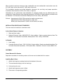
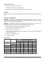
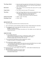
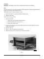
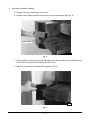
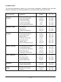
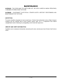
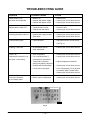
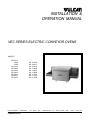
INSTALLATION &
OPERATION MANUAL
VEC SERIES ELECTRIC CONVEYOR OVENS
MODELS
VEC3018
10KW
15KW
VEC4018
VEC3624
VEC3632
VEC4824
VEC4832
VEC6024
VEC6032
VULCAN-HART
ML-126198
ML-126401
ML-126199
ML-114836
ML-114837
ML-114838
ML-114739
ML-114797
ML-114798
COMPANY,
FORM 31062 (10-98)
P.O.
BOX
696,
LOUISVILLE,
KY
40201-0696,
TEL.
(502)
778-2791
TABLE OF CONTENTS
GENERAL............................................................................................................................................. 3
INSTALLATION .................................................................................................................................... 3
Unpacking ................................................................................................................................. 3
Location .................................................................................................................................... 3
Installation Codes and Standards ........................................................................................... 4
Assembly .................................................................................................................................. 4
Leveling .................................................................................................................................... 5
Electrical Connections ............................................................................................................. 5
OPERATION ........................................................................................................................................ 6
Controls .................................................................................................................................... 6
Before First Use ....................................................................................................................... 7
Using the Oven ......................................................................................................................... 7
Cleaning .................................................................................................................................... 9
Conveyor Belt Assembling and Disassembling .................................................................... 13
Cooking Chart ........................................................................................................................ 14
MAINTENANCE ................................................................................................................................. 15
Inspection ............................................................................................................................... 15
Service and Parts Information ............................................................................................... 15
TROUBLESHOOTING GUIDE .......................................................................................................... 16
© VULCAN-HART COMPANY, 1998
—2—
Installation, Operation and Care of
MODEL VEC SERIES ELECTRIC
CONVEYOR OVENS
PLEASE KEEP THIS MANUAL FOR FUTURE USE
GENERAL
Vulcan-Hart ovens are produced with quality workmanship and material. Proper installation, usage,
and maintenance of your oven will result in many years of satisfactory performance.
It is suggested that you thoroughly read this entire manual and carefully follow all of the instructions
provided.
INSTALLATION
Before installing, verify that the electrical service agrees with the specifications on the rating plate
located on the right front side panel. If the supply and equipment requirements do not agree, do not
proceed with the installation. Contact your Vulcan-Hart service representative immediately.
UNPACKING
This oven was inspected before leaving the factory. The transportation company assumes full
responsibility for safe delivery upon acceptance of the shipment. Immediately after unpacking, check
for possible shipping damage. If the oven is found to be damaged, save the packaging material and
contact the carrier within 15 days of delivery.
1. Tilt the oven on its back side.
2. Place the oven on a four-wheel dolly.
3. Move oven to its installation position.
4. Remove oven from the dolly and place on two pieces of 2 x 4 wood.
5. Carefully unpack oven.
Do not use the door or handle to lift oven.
LOCATION
When the crate is turned on its side, the oven will pass through a 34" (86 cm) door opening (or 30"
[76 cm] opening without the crate). Verify that the doors and access routes into the kitchen area will
permit clearance.
—3—
When installed, minimum clearance from combustible and non-combustible construction must be
2.5" (63.5 mm) at the sides and 2.5" (63.5 mm) at the rear.
The installation location must allow adequate clearances for servicing and proper operation.
A minimum front clearance of 36" (914.4 mm) is required.
Information on the construction and installation of ventilating hoods may be obtained from the
standard for "Vapor Removal from Cooking Equipment," NFPA No. 96 (latest edition), available from
the National Fire Protection Association, Batterymarch Park, Quincy, MA 02269.
Exhaust: Approximately 2000 CFM required for double stacked ovens.
Approximately 1500 CFM required for single oven.
Make-up air should be 65% to 80% of the exhaust air rating.
INSTALLATION CODES AND STANDARDS
The oven must be installed in accordance with:
In the United States of America:
1. State and local codes.
2. National Electrical Code, ANSI/NFPA-70 (latest edition). Copies may be obtained from The
National Fire Protection Association, Batterymarch Park, Quincy, MA 02269.
In Canada:
1. Local codes.
2. Canadian Electrical Code, CSA C22.2 No. 3 (latest edition). Copies may be obtained from The
Canadian Standard Association, 178 Rexdale Blvd., Etobicoke, Ontario, Canada M9W 1R3.
ASSEMBLY
Ovens Mounted On Casters
Separate instructions for installing casters to the oven are included with the casters.
Installing Basic Oven
1. Attach front legs by screwing them into the bottom of the oven.
2. Tilt oven forward resting it on the front legs.
3. Lift oven from the rear.
4. Attach back legs once oven is lifted.
5. Place oven in its operating position.
—4—
Installing Stacked Ovens
1. Stack ovens after basic oven is installed.
2. Lift top oven and place it on top of bottom oven.
3. No fasteners are required; the weight of the oven will keep it in place.
LEVELING
Casters for this oven are of the non-adjustable type. For best results oven should be installed on a level
floor.
ELECTRICAL CONNECTIONS
WARNING: ELECTRICAL AND GROUNDING CONNECTIONS MUST COMPLY WITH THE
APPLICABLE PORTIONS OF THE NATIONAL ELECTRICAL CODE ANSI/NFPA 70 (LATEST EDITION)
AND/OR OTHER LOCAL ELECTRICAL CODES.
WARNING: DISCONNECT ELECTRICAL POWER SUPPLY AND PLACE A TAG AT THE
DISCONNECT SWITCH TO INDICATE YOU ARE WORKING ON THE CIRCUIT.
1. Remove wiring compartment cover from the right rear of the oven.
2. Run power supply cord through the conduit fitting.
3. Connect wires at the terminal block.
4. Follow the appropriate wiring diagram that is included with this manual when making connections
at the electric supply lines.
5. Replace wiring compartment cover.
6. Turn power supply ON.
Electrical Data
Oven Model
VEC3018
VEC4018
VEC3624
VEC3632
VEC4824
VEC4832
VEC6024
VEC6032
Total Kw
10
15
15
30
30
45
45
60
60
208V
28
42
42
83
83
125
125
166
166
Nominal Amps Per Line Wire
3 Phase
1 Phase
240V
480V
208V
240V
24
12
48
42
36
18
72
63
36
18
72
63
72
36
144
125
72
36
144
125
108
54
216
188
108
54
216
188
144
72
288
250
144
72
288
250
—5—
OPERATION
WARNING: THE OVEN AND ITS PARTS ARE HOT. BE VERY CAREFUL WHEN OPERATING,
CLEANING OR SERVICING THE OVEN.
CONTROLS (Fig. 1)
TEMPERATURE DISPLAY
SET POINT
INDICATOR
LIGHT
SET POINT
SET POINT ARROWS
TIME DISPLAY
TIME RANGE
SWITCH
BELT SWITCH
POWER SWITCH
TIME KNOB
DRIVE MOTOR FUSES
CONTROL CIRCUIT FUSE
PL-41123-1
Fig. 1
Temperature Display
— Displays actual oven cavity temperature during cooking cycle.
Set Point
— Press to display set temperature.
Set Point Arrows
— Press up or down to reach desired set point temperature.
Set Point Indicator Light
— When lit, indicates that heat is being provided to the oven. When set
point is reached, light will go off.
Time Display
— Displays actual cooking time in minutes and tenths of minutes.
—6—
Time Range Switch
— Use to set cook time range from 2 to 8 minutes, 8 to 15 minutes, or
15 to 20 minutes. Switch must be on cook time range desired in
order to change belt speed.
Belt Switch
— Push switch to ON to start conveyor belt; push to OFF to stop
conveyor belt.
Power Switch
— Press ON to start oven; press OFF to stop oven.
Time Knob
— After Time Range Switch has been set to the desired time range,
turn knob until desired time is reached on the display.
• Turn knob clockwise to increase cook time.
• Turn knob counterclockwise to decrease cook time.
Control Circuit Fuse
— 25 Amp. / 250V. Time delay.
Drive Motor Fuses
— 375 ma / 250V.
BEFORE FIRST USE
1. Clean the protective metal oils from all surfaces of the oven.
2. Use a non-corrosive, grease dissolving commercial cleaner. Follow manufacturer's directions.
3. Rinse thoroughly with a clean damp cloth and wipe dry with a soft clean cloth.
• DO NOT hose down the oven.
• Do not use this oven if its controls have been wet. If the controls are wet, contact your
Vulcan-Hart servicer.
USING THE OVEN
1. Turn main power switch ON.
• Oven will begin operating at the factory set temperature of 525°F (273°C).
• Actual oven cavity temperature will appear in the temperature display.
• Set Point Indicator Light will indicate if the heat is on.
2. Press and hold Set Point button to read the temperature set point.
• Set point will appear in the temperature display.
3. Reset temperature set point (if needed).
a. Press and hold Set Point button, at the same time, press the Set Point Arrows up or down
until the desired set point temperature appears in the digital display.
b. Release Set Point button.
c. The actual oven cavity temperature will display.
If the conveyor belt stalls, the time display will indicate "O.L." and the belt will automatically stop.
a. Remove blockage.
b. Move Belt Switch up and down to reset the control.
• Time should be indicated on the display again.
• Drive motor should restart.
—7—
A baffle (Fig. 2) is located on each end of the oven. It can be adjusted higher or lower to accommodate
the height of the product being cooked.
To raise or lower baffles:
1. Loosen the two thumb screws (Fig. 2) - use insulated gloves.
2. Readjust baffle height.
3. Retighten the two thumb screws.
BAFFLE
THUMB SCREWS
PL-41126-1
Fig. 2
Loading and Unloading the Oven
1. Place product in utensils (if required).
2. Set utensils or products on the entrance end of the belt; not in the oven tunnel.
3. Remove utensils or products from the oven after they completely clear the oven tunnel.
Air Distribution Panels
The oven is equipped with a top and a bottom air distribution panel.
• These panels regulate the quantity of air on the top and bottom of the product that is being cooked.
• They have been adjusted at the factory for proper baking performance.
• Some products may need additional panel adjustments. This should be done by a Vulcan-Hart
authorized servicer.
Shutdown
Press main power switch OFF.
—8—
CLEANING
WARNING: DISCONNECT ELECTRICAL POWER SUPPLY BEFORE CLEANING.
Daily
Clean the outside of the oven daily by wiping with a clean damp cloth. Avoid using abrasive powders
or pads; these cleaners may damage the finish.
Clean right-hand and left-hand crumb trays (Fig. 3).
1. Remove and wash in a sink as you would any normal utensil.
2. Replace crumb trays.
Clean center crumb tray (Fig. 3).
1. Remove front panel.
a. Grasp each side of the door handle and lift up.
b. Swing the bottom of the front panel out.
c. Lower panel and pull away.
2. Loosen the conveyor belt (see Conveyor Belt Removal in this manual) and brush away the
crumbs under the belt.
3. Remove crumb tray.
4. Wash in a sink as you would any normal utensil.
5. Replace the tray and the front panel by reversing this procedure.
CRUMB TRAYS
PL-41127-1
Fig. 3
—9—
Conveyor
To maintain proper belt tension, adjust the conveyor belt to remove any slack.
1. Locate the two adjustment screws (Fig. 4) on the right hand end (facing machine) of the
conveyor assembly.
2. Loosen the nuts on the inside of the conveyor rack and turn the adjusting screws clockwise
to increase belt tension. Be sure to adjust both screws an equal amount.
3. Retighten the nuts on the inside of the conveyor rack.
If the conveyor belt adjustment is at its maximum and the belt is still slack, remove one belt link.
1. Locate the conveyor belt splicing strand and remove it as shown in the CONVEYOR BELT
ASSEMBLING AND DISASSEMBLING (Fig. 8).
2. Remove one conveyor link and set the tension screws at their minimum by turning them
counterclockwise. Adjust both screws an equal amount.
3. Reinstall the splicing strand as shown in the CONVEYOR BELT ASSEMBLING AND
DISASSEMBLING (Fig. 8), and readjust the belt tensions with the adjusting screws.
Two ways to remove conveyor for cleaning:
1. Conveyor Belt Removal
a. Loosen belt tension screws at the end of the belt track (Fig. 4).
b. Locate the wide end-hooks of the splicing strands where the belt should be disconnected.
c. Remove splicing strands by following the directions shown in CONVEYOR BELT
ASSEMBLING AND DISASSEMBLING in this manual.
d. Reverse this procedure to replace the belt.
BELT TENSION SCREWS
Fig. 4
— 10 —
PL-41128-1
2. Conveyor Assembly Removal
a. Remove conveyor crumb trays (see Fig. 3).
b. Remove cover where conveyor shaft enters the left-hand control box (Fig. 5).
REMOVE COVER
PL-41129-1
Fig. 5
c. Lift up the drive end of the conveyor assembly and slide the conveyor assembly into the
oven tunnel to remove the tension on the drive chain.
d. Slip drive chain off the conveyor drive sprocket (Fig. 6).
PL-41130
Fig. 6
— 11 —
e. Pull the entire conveyor assembly from the oven (Fig. 7).
PL-41131
Fig. 7
f. Take conveyor assembly to cleaning area.
g. Reverse this procedure to replace conveyor assembly.
Weekly
CAUTION: Intake fans and slots on the back of the oven and control box must be cleaned
weekly. Any obstructions may cause motor damage.
Use a long bristle brush to clean these areas.
Clean the wire belt and frame with a stiff bristle brush as needed.
— 12 —
CONVEYOR BELT ASSEMBLING AND DISASSEMBLING (Fig. 8)
Install the conveyor belt so that it always runs in the
direction indicated by this arrow — the closed end of
the loop toward the direction of travel.
1
The arrows in the belt illustrate the movement of the
splicing strand between steps.
When bending the splicing strand, try to limit bending
to straight portions of the strand rather than in the "Z"
bend area.
2
3
4
Splice one side completely before starting the other
side.
5
After completely splicing the belt, it is advisable to go
along the width of the belt straightening the splicedin strand.
6
Depending upon the width of the belt, there might be
one, two, or three splicing strands.
7
PL-52997
Fig. 8
— 13 —
COOKING CHART
The times and temperatures shown in this chart are only suggestions. Experiment with your food
products to determine the cooking temperatures and times that give you the best results.
APPROX. TIME
(IN MIN.)
TEMP.
(°F) / (°C)
TYPE OF FOOD
PRODUCT
ITALIAN
Pizza (par baked dough)
Pizza (fresh dough)
Pizza (thick pan type)
Calzone (fresh dough)
Pastas (precooked to gratin)
4 to 4.5
5.5 to 6.5
7.5 to 8.5
5 to 6
5 to 6
510
510
510
510
510
BREADS & SUBS
Garlic Bread
Bread Sticks
Submarine Sandwiches
2.5 to 3.5
2.5 to 3.5
2.5 to 3.5
510 / 265
510 / 265
510 / 265
BAKERY
Dinner Rolls (par baked)
Dinner Rolls (fresh)
Bagels (fresh)
Croissants (par baked)
Croissants (fresh)
Muffins (fresh)
Biscuits and Cookies (fresh)
4 to 4.5
7.5 to 8.5
12 to 13
4 to 4.5
9 to 10
12 to 13
4.5 to 6.5
390
390
390
390
390
390
390
/
/
/
/
/
/
/
199
199
199
199
199
199
199
MEAT & POULTRY
Chicken Wings (precooked)
Chicken Wings (fresh)
Chicken Breasts (boneless)
B.B.Q. Ribs (fresh)
Hamburger Patties (fresh)
5.5
18
5.5
18
5.5
6.5
20
6.5
20
6.5
510
390
510
390
510
/
/
/
/
/
265
199
265
199
265
FISH & SEAFOOD
Shrimp (fresh)
Fish Filets (fresh)
Tuna Steak (fresh)
Salmon Steak (fresh)
4.5 to 5.5
6.5 to 7.5
8.5 to 9.5
6 to 7.5
510
510
510
510
/
/
/
/
265
265
265
265
MEXICAN
Burritos and Enchiladas
Nachos Assorted Styles
2.5 to 3.5
2.5 to 3.5
475 / 246
475 / 246
EGGS
Souffles and Omelettes
Quiches
5.5 to 6.5
9 to 10
510 / 265
390 / 199
— 14 —
to
to
to
to
to
/
/
/
/
/
265
265
165
265
265
MAINTENANCE
WARNING: THE OVEN AND ITS PARTS ARE HOT. BE VERY CAREFUL WHEN OPERATING,
CLEANING OR SERVICING THE OVEN.
WARNING: DISCONNECT ELECTRICAL POWER SUPPLY BEFORE PERFORMING ANY
MAINTENANCE ON THE OVEN.
INSPECTION
The oven should be inspected at least annually by a Vulcan-Hart authorized servicer. More frequent
cleaning may be required due to oven grease vapors, dust, etc. It is imperative that control
compartments and circulating air passageways of the oven be kept clean.
SERVICE AND PARTS INFORMATION
To obtain service and parts information concerning this oven, contact your local Vulcan-Hart Service
Office.
— 15 —
TROUBLESHOOTING GUIDE
PROBLEM
Power switch is on,
but oven will not operate.
POSSIBLE CAUSES
• Blown fuse.
• Problem with power supply.
• Problem with power switch.
ACTION
• Replace fuse.
• Contact your Vulcan-Hart servicer.
• Contact your Vulcan-Hart servicer.
Speed control shows "OL".
• Conveyor belt is stuck.
• Problem with belt motor.
• Check the belt.
• Contact your Vulcan-Hart servicer.
Conveyor belt does not turn.
• Problem with speed control.
• Gear loose.
• Contact your Vulcan-Hart servicer.
• Contact your Vulcan-Hart servicer.
Conveyor belt jumps.
• Chain too loose.
• Adjust belt tension screws evenly
(see Fig. 4).
Cooking is not even.
• Air distribution panels
need adjustment.
• Contact your Vulcan-Hart servicer.
Oven is on,
temperature controller is on,
but oven is not heating.
• Axial fan problem.
• Fan circulating motor is
overloaded or overheated.
• Temperature controller
setting not properly adjusted.
• Problem with thermocouple.
• Hi-limit switch activated.
• Contact your Vulcan-Hart servicer.
• Contact your Vulcan-Hart servicer.
• Blower cage is unbalanced.
• Contact your Vulcan-Hart servicer.
Excessive vibrations
of circulating motor.
• Adjust temperature controller.
• Contact your Vulcan-Hart servicer.
• Press reset button (Fig. 9) located
on the back panel (control side).
Contact your Vulcan-Hart servicer.
RESET BUTTON
PL-41201-1
Fig. 9
FORM 31062 (10-98)
— 16 —
PRINTED IN U.S.A.