1
SX50/SX50H
Sump Pumps
Used in Hazardous Locations Class 1, Division 1, Group D
Installation and Service Manual
23833A465 03/10
WARNING! IMPORTANT SAFETY INSTRUCTIONS! READ CAREFULLY BEFORE
INSTALLATION. This manual contains important information for the safe use of this
product. Read this manual completely before using this product and refer to it often
for continued safe product use. DO NOT THROW AWAY OR LOSE THIS MANUAL. Keep it in a safe place so that you may refer to it often.
GENERAL
19. Keep hands and feet away from impeller when
power is connected.
20. Submersible sump pumps are not approved
for use in swimming pools, recreational water
installations, decorative fountains or any
installation where human contact with the
pumped fluid is common.
21. Do not operate pump without safety devices
in place.
22. For hazardous locations, use pumps that are
listed and classified for such locations.
1. Most accidents can be avoided by using
COMMON SENSE.
2. Read the operation and maintenance
instructions manual supplied with the pump.
3. Do not wear loose clothing that can become
entangled in the impeller or other moving
parts.
4. This pump is designed to handle materials that
could cause illness or disease through direct
exposure. Wear adequate protective clothing
when working on the pump or piping.
IMPORTANT! Myers is not responsible for
losses, injury or death resulting from a failure
to observe these safety precautions, misuse or
abuse of pumps or equipment.
ELECTRICAL
5. To reduce the risk of electrical shock, pump
must be properly grounded in accordance with
the National Electric Code and all applicable
state and local codes and ordinances.
6. To reduce risk of electrical shock, disconnect
the pump from the power source before
handling or servicing.
7. Any wiring to be done on pumps should be
done by a qualified electrician.
8. Never operate a pump with a power cord that
has frayed or brittle insulation.
9. Never let cords or plugs lie in water.
10. Never handle connected power cords with
wet hands.
GENERAL INFORMATION
Pump Models: These instructions cover the
installation and service of the Myers SX50 and
SX50H series submersible sump pumps. The
motors are CSA listed for hazardous sewage
locations Class 1, Div. 1, Group D.
Motor HP & Voltages: The SX50/SX50H sump
pumps are offered in single and three phase.
Voltages will vary according to the application and
can be seen in the tables in this manual.
PUMPS
Electrical Controls: All of these pump models must
be used with a control panel. Myers built control
panels are designed to supply the correct electrical
controls, motor starting equipment and include
the circuitry for moisture and heat sensors. It is
recommended that a Myers built control panel be
used so that all warranties apply.
11. Pump builds up heat and pressure during
operation; allow time for pump to cool before
handling or servicing.
12. Only qualified personnel should install,
operate or repair pump.
13. Keep clear of suction and discharge openings. DO NOT insert fingers in pump with power
connected.
14. Do not pump hazardous material not
recommended for pump (flammable,
caustic, etc.).
15. Make sure lifting handles are securely
fastened each time before lifting.
16. Do not lift pump by the power cord.
17. Do not exceed manufacturer's
recommendation for maximum performance,
as this could cause the motor to overheat.
18. Secure the pump in its operating position so it
cannot tip over, fall or slide.
23833A465
General Construction: The SX50/SX50H motor
construction is designed to meet CSA requirements
for Class 1, Group D sewage applications. These
models are approved and nameplated with a CSA
file number. A cross sectional view of the internal
workings of the pumps can be seen on pages 7 and
8. The motor chamber and seal chamber are filled
with a high dielectric type oil for improved lubrication
and heat transfer of the bearings and motor. Since
the bearings have been designed for 50,000 hours
of life, the oil should never require replacement
2
under normal operating conditions. An air space
above the oil level in both the seal and motor
chambers is provided to allow for the expansion of
the oil when at operating temperature. The power
and control lines are sealed and strain relieved on
the outside entrance with a standard cord grip, and
internally through the use of a dielectric potting resin
surrounding the electrical wires.
This circuitry is provided in the Myers control panel
designs.
The SX50/SX50H pumps are equipped with
internal thermostats. The SX50/SX50H models
are designed to meet Class B heat rise of 266°F
(130°C).
Note: Failure to use proper circuitry and to connect
the motor overheat protection in the control panel
would negate all warranties and CSA Listings.
Internal connection wiring diagrams are shown in
Figure 8. All of the pump fasteners and shafts are
made from corrosion resistant stainless steel, while
the pump castings are made of ASTM A-48 Class
30 cast iron, and the multivane vortex impellers are
made from Class 20 cast iron.
Motor Seal Failure Warning: The seal chamber is
oil filled and provided with moisture sensing probes
to detect water leakage through the lower shaft seal. The probes can also detect moisture present in the
upper motor housing.
General Installation: Various configurations and
methods of plumbing this series of sump pumps may
be used.
The presence of water energizes a red seal leak
warning light at the control panel. This is a warning
light only, and does not stop the motor. It indicates
a leak has occurred and the pump must be repaired. Normally, this indicates the outboard seal has
leaked. Allowing the unit to operate too long after
the warning could cause upper seal leakage along
with motor failure.
Note: If the SX50/SX50H hazardous location
pumps are used in conjunction with a rail lift-out
system, it must be a UL or CSA listed nonsparking
system for hazardous locations.
IMPORTANT: If the following guidelines are
not followed, the CSA hazardous location listing
is void.
The resistance across the moisture sensing (seal
failure) probes should be checked after a seal
leak warning light has lit. This can be done by
disconnecting the red and orange control wires from
the control panel, and measuring the resistance with
an ohmmeter between the wires. The SX50/SX50H
reading should be above 30,000 ohms. If the
measured values are below those indicated above,
the pump may have a lower seal failure and
require service.
These pumps are to be used for handling septic tank
effluent, sewage, and storm water only. Do not use
in other hazardous locations. These motors must
be repaired and serviced only at a Myers authorized
service center or at the Myers factory. Any
unauthorized field repair voids warranty and the
hazardous location rating.
CAUTION: After the pump is installed and
sewage has entered the basin there is Danger. Sewage water gives off methane and hydrogen
sulfide gases, which are poisonous. Never
enter a wet well unless the cover is open for a
sufficient period of time to allow fresh air into
the basin. It is recommended that a man in
the basin have a harness on with a rope to the
surface, so that he can be pulled out in case of
asphyxiation. It is for this reason that Myers
recommends using the rail lift-out system so that
no service is required inside the basin.
On the Myers control panels the seal leak test switch
tests the seal leak circuit continuity. When pushed
the seal leak test bulb should light. If the test bulb
does not light it means either the wiring circuitry to
the seal leak probes have been broken or the bulb
has burned out.
Note: Myers built control panels supply the correct
circuitry for moisture and heat sensor connections. Failure to install the correct circuitry with proper
connection would negate warranty and CSA Listing. See Figure 7.
Motor: Each motor is provided with heat sensor
thermostats attached directly to the motor windings. The thermostats open if the motor windings see
excessive heat and, in turn, open the motor
contactor in the control panel, breaking the power
to the pump. When the motor is stopped due to an
overheat condition, it will not start until the motor has
cooled and the heat sensor reset button is manually
pushed on the front of the Myers control panel. Motor Power Cord, Control Cord and Cord
Cap Assembly: Each motor power cord has 4
conductors – white, black, red and green. For a
single phase motor the black is connected to the
common lead, the white is connected to the main
lead, while the red is connected to the start circuitry,
and the green is attached to a good ground. The
3
23833A465
rotation of a single phase pump is set properly at the
factory.
The float level controls maintain the basin sewage
water level by controlling pump turn-on and
turn-off levels.
For three phase motor, the black, white, and red
conductors are power leads and the green is ground.
1. The lower turn-off control should be set so that
the pump stops with the water covering the entire
motor housing. Consult the factory for any
settings below this point.
Note: Rotation should be clockwise when observed
from the top of the pump. This can be checked by
noting which direction the pump torques upon initial
starting. A properly rotating pump will torque
counterclockwise upon start.
2. The upper turn-on control should be set above
the lower turn-off control. The exact height
between the two controls is determined by the
number of pump starts desired and the depth
of the basin. A maximum of 10 starts per hour
should not be exceeded.
ALWAYS CHECK THREE PHASE PUMPS
FOR PROPER ROTATION BEFORE
INSTALLING PUMPS.
The control cable has 5 conductors – black, white,
red, orange and green. White and black connect
to the heat sensor terminals in the control panels;
red and orange connect to the seal failure terminals
in the control panel; and the green connects to the
ground in the control panel.
3. The override control is set at a specified height
above the upper turn-on control.
4. The alarm control is set about 6" to 12" above the
override control.
5. No control should be set above the inlet invert.
The cord cap is epoxy potted. This allows the cord
cap, with cords, to be removed from the motor. With
this arrangement, the cords can be permanently
installed in a sealed fitting in the sump. This
should be an approved junction box for the specific
hazardous locations. The control and power
cables cannot be spliced!
Electrical Connections: All electrical wiring must
be in accordance with local code and only qualified
electricians should make the installations. Complete
wiring diagrams are included for use in making the
installation. All wires should be checked for shorts
to ground with an ohmmeter or megger after the
connections are made. This is important, as one
grounded wire can cause failure of the pump, control
panel or personal injury.
Note: Each cable has a green ground wire and
must be properly grounded per the National Electric
Code and local codes.
Pump: The fluid end of the pump is field serviceable
and can be disassembled in case of wear, damage,
plugging or outboard seal failure. The following will
describe the disassembly and reassembly process.
Electrical Motor Controls: All electrical controls
and motor starting equipment should be as specified
in these instructions. Consult factory for any
acceptable alternatives. For hazardous locations the
controls and control panel must be installed outside
the hazardous area. Only approved controls that are
intrinsically safe may be used with these pumps.
WARNING! Disconnect pump from power source
before servicing or handling.
Disassembly
1. With the pump located in a secure place, remove
the bolts fastening the seal housing to the volute. The motor and impeller can now be removed as
a unit.
Junction Box: If a junction box is used in a
hazardous location, it must be an approved type
with approved cord connectors. Wires from the
junction box must pass through an approved seal
connector for hazardous locations.
2. Lay the unit down on its side. If the lower seal is
to be removed, it is recommended that the oil in
the seal chamber be drained. This can be done
by removing the lower seal chamber plug and
draining the oil into a holding container.
Level Sensing Controls: Intrinsically safe-type
float controls are recommended for all applications
and required for hazardous locations. An intrinsically
safe control panel relay will limit the current and
voltage to the level controls. A Myers control panel
can be supplied with this type circuitry.
23833A465
4
3. Using a proper wrench, the impeller retaining
nut must be removed. This may require a piece
of wood placed between the vanes to keep the
impeller from rotating while removing the nut.
Loctite® is used on this bolt and heating to
450–500°F may also be required to loosen. The
impeller is mounted on a threaded shaft. To
remove impeller, rotate impeller with one hand,
while holding pump shaft with screwdriver.
seal housing. A piece of PVC pipe that fits onto
the face of the seal works well for installation. With clean cloth, lightly wipe the face of the seal
surface to make sure it is dirt free. Remove the
rotating portion of the seal from the package and
lubricate the inside diameter of the rubber bellows
and the outside diameter of the shaft. Place the
seal over the shaft. Evenly press on the body
of the rotational assembly and slide it down the
shaft until the seal faces meet. A PVC pipe with
the inside diameter slightly larger than the shaft
diameter can work well to press the rotational
assembly into position. Once the seal assembly
is in position, place the spring over the register on
the rotational portion of the seal.
4. If the lower seal needs to be removed, first
remove the compression spring that rides
between the impeller and the seal assembly. Next take a pair of screwdrivers and remove
the compression ring that surrounds the rubber
bellows on the rotating portion of the seal
assembly. Again using the screwdrivers, pry the
remaining portion of the rotating seal assembly
off the shaft. The ceramic stationary can be
removed by placing a screwdriver between the
rubber and the ceramic face, and then prying,
working around the entire diameter. Note,
these parts should be discarded and a new seal
assembly installed.
2. Thread the impeller onto the shaft, making sure
that the seal spring is registered properly onto
the back side of the impeller. Place the proper
Loctite fluid on the impeller retaining nut. Tighten
nut on shaft.
3. Fill the seal chamber with new dielectric oil. An
air gap of 10–15% volume must be left for the
expansion of the oil when it is at operating
temperature.
5. If the oil in the seal chamber was drained,
examine the contents to determine if the upper
seal has been damaged. Signs of grit or other
abrasive material may indicate that the upper
seal has also been damaged. Pressurizing the
motor housing assembly between 7 and 10 psi
and observing any drop in pressure will indicate if
the upper seal is functioning properly.
4. The motor and impeller assembly can be installed
into the volute, making sure that the units are
aligned properly. Install the volute retaining bolts
and tighten.
5. Air tends to trap in the pump case when water
rises in the sump or when the pump is lowered
into the water after service. To vent off this air a
small hole is drilled into the volute casting. Be
sure this vent hole is clean after any service
work on pump. Air venting is not a problem after
initial start.
Note: Upper seal repairs must be done at a Myers
authorized service center or at the Myers factory. Any unauthorized field repair voids warranty and the
CSA listing.
Reassembly
1. Remove the ceramic portion of the new seal from
the package. Brush new dielectric oil around the
rubber portion of the stationary assembly and into
the pocket in the seal housing. Note, keep the
oil off the seal face. Without scratching the seal
face, press the ceramic stationary portion into the
5
23833A465
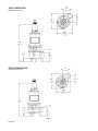
SX50 DIMENSIONS
[Dimensions in mm]
SX50H DIMENSIONS
[Dimensions in mm]
FIG. 1
23833A465
6
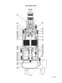
SX50 PUMP PARTS
FIG. 2
7
23833A465
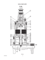
SX50H PUMP PARTS
FIG. 3
23833A465
8
SX50/SX50H PARTS LIST
Ref.
1
2
3
4
5
6
7
8
9
10
11
11
12
13
14
15
16
17
18
19
20
21
22
23
24
25
26
27
28
29
30
31
32
Description
CAP, CORD
CONNECTOR
TUBE, PLASTIC x 1-1/4" LG.
SCREW, CAP 5/16 x 1-1/4" LG.
O-RING, 4-1/2" x 4-1/4" x 1/8"
CAP, UPPER BEARING
O-RING, 4-7/8" x 4-5/8" x 1/8"
PLUG, PIPE 1/4" NPT
SCREW, MACH. #10 x 1/2" LG.
WASHER, LOCK
SCREW, MACH. 5/16 x 1" LG. (SX50)
SCREW, MACH. 5/15 x 1" LG. (SX50H)
HOUSING W/STATOR (1Ø)
HOUSING W/STATOR (3Ø) 230/460V
HOUSING, MOTOR
STATOR ONLY (1Ø)
STATOR ONLY (3Ø) 230/460V
OIL, TRANSFORMER (1 GAL. CAN)
WASHER, SPRING
BEARING, BALL (UPPER)
RING, RETAINING
ROTOR W/SHAFT (1Ø)
ROTOR W/SHAFT (3Ø)
BEARING, BALL (LOWER)
HOUSING, UPPER SEAL
SEAL, SHAFT
RING, RETAINING
ELECTRODE W/RESISTOR
O-RING, 6-1/8" x 5-7/8" x 1/8"
FERRULE, RUBBER
PLUG, SPECIAL
HOUSING, LOWER SEAL
SCREW, CAP 5/16 x 1" LG.
CASE, VOLUTE
SCREW, CAP 1/4 x 1" LG.
IMPELLER, RECESSED
NUT, JAM
SCREW, SET
Qty.
1
7
2
8
1
1
1
2
1
1
2
6
1
1
21571D150K
21571D152K
21571D100X
21656C103
21656C106
11009A008K
19331A005
08565A013
11816A006
26859C101X
26859C104X
08565A018
21574D100X
21576A010
12558A006
22578A003
05876A125
22579A000
21577A000
21578C110X
06106A008
21612D000
19099A012
21663C020
19109A070
05013A027
1
1.06 gal.
2
1
1
1
1
1
1
2
1
1
2
1
1
1
4
1
3
1
1
2
SX50H
22407C602
12762A001
10649A102
19100A012
05876A122
21570B100X
05876A123
05022A054
05434A034
06107A015
07597A017
21571D150K
21571D152K
21571D100X
21656C103
21656C106
11009A008K
19331A005
08565A013
11816A006
26859C101X
26859C104X
08565A018
21574D100X
21576A010
12558A006
22578A003
05876A125
22579A000
21577A000
21578C115X
----26226D012
19099A012
21663C010
19109A070
05013A027
MOTOR ELECTRICAL DATA
SX50/SX50H
Available Models
Standard
SX50-21
SX50H-21
SX50-23
SX50H-23
SX50-43
SX50H-43
SX50
22407C602
12762A001
10649A102
19100A012
05876A122
21570B100X
05876A123
05022A054
05434A034
06107A015
07597A017
Motor Electrical Data
HP
½
½
½
½
½
½
Volts
230
230
230
230
460
460
Phase
1
1
3
3
3
3
Hertz
60
60
60
60
60
60
9
Start Amps
12.5
12.5
10.8
10.8
5.4
5.4
Run Amps
4.9
4.9
3.2
3.2
1.6
1.6
Service Factor
Amps
NEC Code Letter Service Factor
5.9
H
1.2
5.9
H
1.2
4.0
G
1.25
4.0
G
1.25
2.0
G
1.25
2.0
G
1.25
23833A465
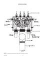
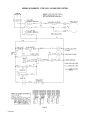
WIRING DIAGRAMS
x
x
"
CORD CONNECTORS
"
"
FIG. 6
NOTE: All components shown must be approved for hazardous locations.
23833A465
10
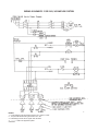
WIRING SCHEMATIC FOR 230V, 1Ø SIMPLEX SYSTEM
FIG. 7
23833A465
11
WIRING DIAGRAM 230V, 1Ø
FIG. 8
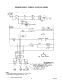
WIRING SCHEMATIC FOR 230V, 3Ø DUPLEX SYSTEM
X
Z
NOTES:
1. Level switches must be rated a minimum of 2 amps @ 120V.
2. Torque all white field wiring terminals to 8 in. lbs.
3. Field wiring must be 60°C copper wire minimum.
4. ---------- = items not supplied in panel.
12
23833A465
WIRING SCHEMATIC FOR 230V, 3Ø SIMPLEX SYSTEM
NOTES:
1. Level switches must be rated a minimum of 2 amps @ 120V.
2. Torque all white field wiring terminals to 8 in. lbs.
3. Field wiring must be 60°C copper wire minimum.
4. ---------- = items not supplied in panel.
23833A465
13
WIRING SCHEMATIC FOR 460V, 3Ø SIMPLEX SYSTEM
NOTES:
1. Level switches must be rated a minimum of 2 amps @ 120V.
2. Torque all white field wiring terminals to 8 in. lbs.
3. Field wiring must be 60°C copper wire minimum.
4. ---------- = items not supplied in panel.
14
23833A465
WIRING SCHEMATIC FOR 460V, 3Ø DUPLEX SYSTEM
X
NOTES:
1. Level switches must be rated a minimum of 2 amps @ 120V.
2. Torque all white field wiring terminals to 8 in. lbs.
3. Field wiring must be 60°C copper wire minimum.
4. ---------- = items not supplied in panel.
Z
CHECK LIST IF PUMP DOES NOT OPERATE PROPERLY
Checking for Moisture in Motor: Use an
ohmmeter or a megger and set on highest scale. Readings on the large power cord between any
of the conductors red, black or white to the green
conductor or to the motor housing should be
greater than 1,000,000 ohms (megohm). A motor
will probably run with a lower reading, but if the
pump is out of service and the value of the reading
is below 1,000,000 ohms (1 megohm), the motor
housing and stator should be removed and baked
in a drying oven at 220°F. This service work should
be done only at an authorized service station. Note, readings should be taken with line leads
disconnected from the control panel.
23833A465
Resistance of Windings: Every motor winding has
a fixed resistance. The windings must check close
to the values given in the tables to operate properly.
See the motor electrical data chart (Figure 4). Use
an ohmmeter and set to the one ohm scale. Read
the resistance with the motor leads disconnected
from the pump control panel.
15
CONDITION
PROBABLE CAUSE
Red light comes on at control box.
This indicates some water has leaked past the lower seal
and has entered the seal chamber and made contact
with the electrode probe. Pump must be removed for
replacement of lower seal. This preventive repair will save
an expensive motor.
Overload trips at control box and alarm buzzer or flashing
red light comes on due to high water level in basin.
1. Push in on red reset button to reset overload. If
overload trips again after short run, pump has some
damage and must be removed from basin for checking.
2. Trouble may be from clogged impeller causing motor to
overload or could be from failed motor.
3. Trouble may be from faulty component in control box. Always check control box before removing pump.
Yellow run light stays on continuously.
1. Indicates H-O-A switch may be in the Hand position.
2. Level control switch may have failed causing pump to
continue to operate when water is below lower control.
3. Impeller may be partially clogged causing pump to
operate at very reduced capacity.
4. Gate valve or check valve may be clogged causing low
pump flow.
5. Pump may be air locked.
Circuit breaker trips.
1. Reset breaker by pushing completely down on handle
then back to On position. If breaker trips again in few
seconds it indicates excessive load probably caused
by a short in the motor or control box. Check out
instructions given with control box before pulling pump.
2. If this condition happens after an electrical storm,
motor or control box may be damaged by lightning.
3. Resistance reading of the motor with lead wires
disconnected from the control box can determine if
trouble is in motor or control box.
Pump is noisy and pump rate is low.
1. Impeller may be partially clogged with some foreign
objects causing noise and overload on the motor.
Grease and solids have accumulated around pump and
will not pump out of basin.
1. Lower control switch may be set too high.
2. Run pump on Hand operation for several minutes with
small amount of water running into basin to clean out
solids and grease. This allows pump to break suction
and surge which will break up the solids. If level switch
is set properly this condition generally will not occur.
3. Trash and grease may have accumulated around floats
causing pump to operate erratically.
IMPORTANT – Pump should be thoroughly cleaned of trash and deposits before starting disassembly operations.
CAUTION – DISCONNECT ALL POWER AND CONTROL WIRES TO MOTOR AT CONTROL PANEL BEFORE
STARTING DISASSEMBLY OPERATIONS. NEVER RELY ON OPENING CIRCUIT BREAKER ONLY.
16
23833A465
NOTES
23833A465 67$1'$5'/,0,7(':$55$17<
0\HUVZDUUDQWVLWVSURGXFWVDJDLQVWGHIHFWVLQPDWHULDODQGZRUNPDQVKLSIRUDSHULRGRIPRQWKVIURPWKHGDWH
RIVKLSPHQWIURP0\HUVRUPRQWKVIURPWKHPDQXIDFWXULQJGDWHZKLFKHYHURFFXUVILUVWSURYLGHG WKDWVXFK
SURGXFWV DUH XVHG LQ FRPSOLDQFH ZLWK WKH UHTXLUHPHQWV RI WKH 0\HUV FDWDORJ DQG WHFKQLFDO PDQXDOV IRU XVH LQ
SXPSLQJUDZVHZDJHPXQLFLSDOZDVWHZDWHURUVLPLODUDEUDVLYHIUHHQRQFRUURVLYHOLTXLGV
'XULQJWKHZDUUDQW\SHULRGDQGVXEMHFWWRWKHFRQGLWLRQVVHWIRUWK0\HUVDWLWVGLVFUHWLRQZLOOUHSDLURUUHSODFHWR
WKHRULJLQDOXVHUWKHSDUWVZKLFKSURYHGHIHFWLYHLQPDWHULDOVDQGZRUNPDQVKLS0\HUVUHVHUYHVWKHULJKWWRFKDQJH
RULPSURYHLWVSURGXFWVRUDQ\SRUWLRQVWKHUHRIZLWKRXWEHLQJREOLJDWHGWRSURYLGHVXFKDFKDQJHRULPSURYHPHQW
IRUSULRUVROGDQGRUVKLSSHGXQLWV
6WDUWXSUHSRUWVDQGHOHFWULFDOVFKHPDWLFVPD\EHUHTXLUHGWRVXSSRUWZDUUDQW\FODLPV:DUUDQW\LVHIIHFWLYHRQO\LI
0\HUVDXWKRUL]HGFRQWUROSDQHOVDUHXVHG$OOVHDOIDLODQGKHDWVHQVLQJGHYLFHVPXVWEHKRRNHGXSIXQFWLRQDODQG
PRQLWRUHGRUWKLVZDUUDQW\ZLOOEHYRLG0\HUVZLOORQO\FRYHUWKHORZHUVHDODQGODERUWKHUHRIIRUDOOGXDOVHDOSXPSV
8QGHUQRFLUFXPVWDQFHZLOO0\HUVEHUHVSRQVLEOHIRUWKHFRVWRIILHOGODERUWUDYHOH[SHQVHVUHQWHGHTXLSPHQW
UHPRYDOUHLQVWDOODWLRQFRVWVRUIUHLJKWH[SHQVHVWRDQGIURPWKHIDFWRU\RUDQDXWKRUL]HG0\HUVVHUYLFHIDFLOLW\
7KLVOLPLWHGZDUUDQW\ZLOOQRWDSSO\DWRGHIHFWVRUPDOIXQFWLRQVUHVXOWLQJIURPIDLOXUHWRSURSHUO\LQVWDOORSHUDWHRU
PDLQWDLQWKHXQLWLQDFFRUGDQFHZLWKWKHSULQWHGLQVWUXFWLRQVSURYLGHGEWRIDLOXUHVUHVXOWLQJIURPDEXVHDFFLGHQW
RUQHJOLJHQFHFWRQRUPDOPDLQWHQDQFHVHUYLFHVDQGSDUWVXVHGLQFRQQHFWLRQZLWKVXFKVHUYLFHGWRXQLWVZKLFK
DUHQRWLQVWDOOHGLQDFFRUGDQFHZLWKDSSOLFDEOHORFDOFRGHVRUGLQDQFHVDQGJRRGWUDGHSUDFWLFHVHLIWKHXQLWLV
PRYHGIURPLWVRULJLQDOLQVWDOODWLRQORFDWLRQILIXQLWLVXVHGIRUSXUSRVHVRWKHUWKDQIRUZKDWLWLVGHVLJQHGDQG
PDQXIDFWXUHGJWRDQ\XQLWZKLFKKDVEHHQUHSDLUHGRUDOWHUHGE\DQ\RQHRWKHUWKDQ0\HUVRUDQDXWKRUL]HG
0\HUVVHUYLFHSURYLGHUKWRDQ\XQLWZKLFKKDVEHHQUHSDLUHGXVLQJQRQIDFWRU\VSHFLILHG2(0SDUWV
:DUUDQW\([FOXVLRQV0<(560$.(612(;35(6625,03/,(':$55$17,(6:+,&+(;7(1'%(<21'
7+('(6&5,37,21217+()$&(+(5(2)0<(5663(&,),&$//<',6&/$,067+(,03/,(':$55$17,(6
2)0(5&+$17$%,/,7<$1'),71(66)25$1<3$57,&8/$5385326(
/LDELOLW\ /LPLWDWLRQ ,1 12 (9(17 6+$// 0<(56 %( /,$%/( 25 5(63216,%/( )25 &216(48(17,$/
,1&,'(17$/ 25 63(&,$/ '$0$*(6 5(68/7,1* )520 25 5(/$7(' ,1 $1< 0$11(5 72 $1< 0<(56
352'8&7 25 3$576 7+(5(2) 3(5621$/ ,1-85< $1'25 3523(57< '$0$*( 0$< 5(68/7 )520
,03523(5 ,167$//$7,21 0<(56 ',6&/$,06 $// /,$%,/,7< ,1&/8',1* /,$%,/,7< 81'(5 7+,6
:$55$17<)25,03523(5,167$//$7,210<(565(&200(1'6,167$//$7,21%<352)(66,21$/6
6RPHVWDWHVGRQRWSHUPLWVRPHRUDOORIWKHDERYHZDUUDQW\OLPLWDWLRQVRUWKHH[FOXVLRQRUOLPLWDWLRQRILQFLGHQWDO
RUFRQVHTXHQWLDOGDPDJHVDQGWKHUHIRUHVXFKOLPLWDWLRQVPD\QRWDSSO\WR\RX1RZDUUDQWLHVRUUHSUHVHQWDWLRQVDW
DQ\WLPHPDGHE\DQ\UHSUHVHQWDWLYHVRI0\HUVVKDOOYDU\RUH[SDQGWKHSURYLVLRQKHUHRI
0\HUV3DUNZD\
$VKODQG2KLR
ZZZIHP\HUVFRP
23833A465 03/10
START-UP REPORT
Installing Contractor: _____________________________________ Phone: _________________________
Sales Contact: __________________________________________ Phone: _________________________
Customer & Location _____________________________________________________________________
1.
SYSTEM INFORMATION
A. Size of wet well: __________________________________ Manufacturer:_____________________
B. Discharge from bottom of basin: ___________________ Location: __________________________
C. Inlet from bottom of basin:________________________ Location: __________________________
D. Type of check valves: ______________________________________________________________
E. Type of piping ____________________________________________________________________
F. Does system have suction and discharge gauges? _______________________________________
G. Pressure reading? Suction_____________________ Discharge _________________________
H. Liquid being pumped:____________________ Temperature: __________ % of solid: __________
I. Sketch or photograph of system attached? _____________________________________________
J. Any additional comments on system: __________________________________________________
__________________________________________________________________________________
2.
ELECTRICAL INFORMATION
A. Control panel part #:__________________________
Panel rated amps: ___________________
Manufacturer ___________________________ Voltage: __________
Phase: _____________
B. Heater size: _____________________________________________________________________
C. Location of panel to wet well: ________________________________________________________
D. Incoming line voltage: _________________________ Actual? _____________________________
E. Voltage to pumps ____________________________ Actual? _____________________________
F. Type of junction box: _____________________________ Manufacturer:_______________________
G. Are floats installed in wet well? _______________________________________________________
H. Are floats set to engineer’s spec? ____________________________________________________
I. Are floats wired for proper sequencing? ________________________________________________
J. Any additional comments on electrical: ________________________________________________
__________________________________________________________________________________
3.
PUMP INFORMATION
A. Type of pump:______________________________________ Serial # ______________________
B. Voltage:_____________ Phase:_____________ RPM:_____________ Amps: ___________
C. Impeller size: ______________ C.O.S. TDH:________________ GPM: ___________________
D. Voltage supplied from panel:___________________ Actual?: _____________________________
E. Actual amperage (all phases): _____________ amps _____________amps _____________amps
F. Have you checked pump rotation? ____________________________________________________
G. Any additional comments on pumps: __________________________________________________
__________________________________________________________________________________
Acknowledge that all information is accurate and proper procedures have been followed:
Customer Signature:__________________________________________________ Date ___________
Start-up Technician:__________________________________________________
Date __________
Send to: Warranty Department, 740 E. Ninth Street, Ashland, OH 44805, Fax: 419-207-3344,
or e-mail to: [email protected]
We will make this a permanent part of our file on this order.
cut along dotted line
Distributor______________________________________________________Order #: _________________