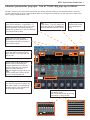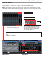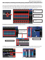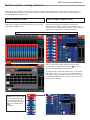
1
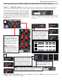
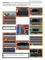
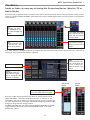
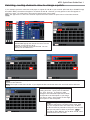
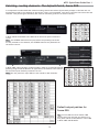
M7CL Quick Start Guide Part 1
Quick Start Guide
A guide for people using M7CL Version 3 in the real world.
Part 1
An introductory guide to the M7CL group of consoles including features
included in Version 3 Firmware and the M7CL-48ES hardware.
These guides are for people about to use the
M7CL for the first time, or for experienced
users requiring some tips and tricks for better
understanding of M7CL and its PC based
software partner the M7CL editor.
1
M7CL Quick Start Guide Part 1
M7CL Quick Start Guides.
The M7CL Quick Start Guide is in multiple parts. It is available as a download from www.yamahaproaudio.com in
the “Self Training” area. Also available is the revised M7CL Short-cuts and Tips List.
Part 1 is an introduction to the M7CL and its variations and goes on to describe the basic operations of the console to the level of a similar featured analogue console.
Part 2 introduces the extra features provided only by digital consoles; the internal effects rack package and the
basic use of scenes to store and recall parameters.
Part 3
looks at scene memory use in more detail and the connection of the PC based software for remote control
and setup; Studio Manager and M7CL Editor.
M7CL-48ES users may also wish to look at Yamaha’s EtherSound Setup Guide. This explains the basic principals of
designing an EtherSound network.
Table of Contents
A quick guide to the M7CL hardware versions
M7CL related hardware
Preparing the console before you start
Scene 000 or Initialization?
Getting sound from M7CL-48/32 in 10 easy steps
Getting sound from M7CL-48ES and SB168-ES in 2 easy stages
............3
............4
............5
............5
............6
............7
The Basics;
............8
Accessing the channel
Changing the channel parameters. HA popup; +48V.
Channel parameter pop-ups. From Overview
Channel parameter pop-ups. From Single Channel View
Sends on fader; an easy way of mixing Mix Groups/auxiliaries.
(Monitor, Effect or Matrix Sends)
Channel parameter pop-ups. The ATT/HPF/EQ pop-up in detail
Naming Channels
Patching, routing channels. How to change a patch
Patching, routing channels. The default Patch, Scene 000
Mix outputs; selecting aux/sub group, pre/post fade,
send point etc
Matrix outputs; routing, features
Trouble shooting ideas
2
......8
......9
.....10
.....11
.....12
...........13
...........14
...........15
...........16
...........17
...........18
...........19
M7CL Quick Start Guide Part 1
A quick guide to the M7CL hardware versions.
There are three different hardware versions. They look and work the same way in operation, but offer different
numbers of channels and locations for the mic inputs.
M7CL-48
M7CL-48 has 48 mono channels with mic preamps on
the rear panel. There are also four stereo channels
with identical mic pre-amps on the rear. There are 16
Omni output XLRs on the rear. (An Omni output is one
that can be patched to different output channels by the
user.)
M7CL-32
M7CL-32 has 32 mono channels with mic preamps on
the rear panel. There are also four stereo channels
with identical mic pre-amps on the rear. There are 16
Omni output XLRs on the rear. (An Omni output is one
that can be patched to different output channels by the
user.)
M7CL-48ES
M7CL-48ES has the same 48 mono channels and four
stereo channels as M7CL-48 but only 8 mic pre-amps
and 8 Omni output XLRs on the rear. To connect more
microphones, remote mic input stage boxes such as
SB168-ES should be added. These are daisy chain
connected via Cat5e cable. The connection system uses
EtherSound protocol and M7CL-48ES has EtherSound
ports on the rear panel. The EtherSound ports are not
found as standard on the other, non-ES, models.
M7CL-48ES uses an innovative Auto Configure mode for
easy setup in the standard configuration.
Note; You can find background information to EtherSound connectivity as a download from Yamaha’s
www.yamahaproaudio.com Self Training area. Look for Networked Audio>> EtherSound Setup Guide.
3
M7CL Quick Start Guide Part 1
M7CL related hardware
M7CL-48 and M7CL-32 are “all in one box” digital mixers that require no setup and no additional units before use.
They differ only in the number of available inputs. M7CL-48ES requires connection to external HA (Head Amps)
before use and we recommend SB168-ES, but other EtherSound compatible HA are also possible like Yamaha AD8HR
connected to NAI48-ES EtherSound interface. The basic setup of M7CL-48ES with SB168-ES is extremely straightforward and is dealt with on page 5. When setup, M7CL-48ES behaves just like an M7CL-48, with only few differences.
This guide will use M7CL-48 as its example and only refer to the other versions where the differences are relevant.
And don’t forget the PC software; Studio Manager and M7CL Editor.
SB168-ES
SB168-ES is a dedicated EtherSound remote mic preamp and
AD convertor ideal for use with M7CL48-ES consoles. The
preamp design and sound is very similar to the M7CL internal preamps.
It can be connected directly to M7CL-48ES with Cat5e. If
the front panel dipswitches are set correctly the combination of M7CL-48ES and multiple SB168-ES will auto configure
themselves to provide extra remote mic preamps patched
to and controlled by the 48 channels in the console. There
is no need for AVS ES Monitor, the PC based patching program
PW800W
PW800W is an optional external
redundant power supply.
MBM7CL
MBM7CL is the meterbridge part.
Although an optional extra, most
consoles are supplied with this.
LA1L
LA1L is Yamaha’s LED gooseneck
lamp. LED lamps have a long
reliable bulb life and white light.
USB memory
USB memory devices are used to
transfer or “back-up” data on the
M7CL. Yamaha do not manufacture
these, but they are widely available from many manufacturers and
computer stores.
Tip; When choosing a storage device remember that; M7CL is USB1.1 compliant, so both USB1.1 and USB2.0
will work. Storage capacity must not exceed 16 GB. The drive can be formatted to FAT12 FAT16 or FAT32 but
must not be partitioned. You can format a new drive in M7CL, but remember formatting a drive erases all its
memories. Most USB memory devices work, but Yamaha have a list of tested ones on www.yamahapropaudio.com
(Downloads>Technical Documents & Data> Utilities and Data> Mixers)
MY (MiniYGDAI) cards
M7CL is compatible with most
MY16/8/4 series cards. MY cards
offer alternative format input
and extra alternative outputs.
Add MY cards if you want more
than 16 outputs or for multitrack recording.
Check www.yamahaproaudio.com for the full
range of MY cards.
4
M7CL Quick Start Guide Part 1
Preparing the console before you start.
Check your console firmware version.
This guide relates to M7CL Version 3 console firmware. If you
have older firmware we recommend an upgrade to version 3. The
firmware can be freely downloaded from
www.yamahaproaudio.
com>>Downloads.
V3.xx
V3.xx
Scene 000 or Initialization?
Before working on an analogue console it is customary to check that the console has been “set to zero”. This
normally means setting the gain to minimum, the EQ to flat, auxes to flat, group routing de-selected, insert points
switched off, etc. Look at and check upwards of 1000 knobs! Because M7CL can memorise its settings, Yamaha have
provided a handy memorised scene (Scene000) where the console is set to zero ready to start at the touch of a
button.
Scene 000
To recall Scene 000 press the up/down keys until SCENE
000 flashes in the [Scene Panel]. Then press [RECALL]
However certain features of M7CL are not under scene control. For example word clock settings, Outport settings
and User Defined Keys are not recalled by scene control. Also, as we will explore in later parts of the User Guide
various things normally controlled by scenes can be actively removed from scene control. This can mean that
recalling Scene 000 does not “set to zero” as expected. Returning the whole console to factory default setting is
called “Initialization” and this is recommended when starting a completely new project.
Note; Initialization removes all user settings from the console and so should only be done if any valuable
user data on the console is backed up. (To a USB memory key or Studio Manager/M7CL Editor file on a PC).
Tip;
Users, particularly in fixed installs, may wish to create their own “Session Starting Point” saved to a
USB key rather than using the factory default. This “Session Starting Point” could include correct port delays
and output patching.
Not included in Scene recall. (So not reset by Scene 000)
but still remembered for all scenes.
Sends on fader selected
Metering point selection
External HA to Slot assignment and HPF.
User Access Level
Network settings
Clock!!
Slots and MY Card settings
User Libraries
EQ/HPF, (User and ROM)
Dynamics (not key-in), (User and ROM)
GEQ, (User only)
Effects (User and ROM)
User defined keys
Preferences
Brightness controls
OUTPORT delay and level settings
MIDI setup
Wordclock
Master +48V
CUE Pop-up; PFL trim ins, DCA trim, PFL trim Outs
Monitor Pop-up; (levels, source on/off, mono, link)
Oscillator (all parameters)
Safe assignments (mute, recall)
Passwords/Admin/guest settings
Screen page or pop-up
5
M7CL Quick Start Guide Part 1
Initialization
To initialize the console power up whilst holding down the Scene [STORE] button. Keep holding the [STORE] button
until the screen shows a pop-up with an invitation to Initialize all memories. After confirming the initialization exit
to the normal boot up sequence.
Power on,
holding
[STORE]
Getting sound from M7CL-32/48 in 10 easy steps.
3
4
2
1
1 Connect a mic or other source (CD
etc) to a chosen input (eg 1)
2 Connect your main L&R to the Outputs 15(L) and 16(R). (7 and 8 for
M7CL-48ES).
5
6
8
7
9
3 Press the blue [SEL] button to select
the channel and assign the encoders.
4 Turn the HA or Headamp gain encoder
to set the gain using the channel meter.
5 Keep the signal below the red “OVER”
at all times.
6 Check the channel is ON and 7 push
up the fader.
8 Check the Stereo master (pink) channel is turned ON and 9 push up the
fader.
10 You should have sound at your
outputs. If not, check the trouble
shooting ideas on page 19!
6
M7CL Quick Start Guide Part 1
Getting sound from M7CL-48ES and SB168-ES in 2 easy stages!
Stage 1. Setup the system.
M7CL-48ES needs to be combined with extra EtherSound compatible HA
inputs. We recommend SB168-ES; they contain similar HA units and are designed to integrate with M7CL-48ES.
With the dipswitches set as shown below the combination of M7CL-48ES and SB168-ES will AUTO CONFIGURE
the EtherSound network in daisy chain mode. NO PC
is required. In AUTO CONFIGURE mode the EtherSound
patching is locked, if you wish to make changes or incorporate other EtherSound devices, use AVS-ES Monitor
from AuviTran.
You can AUTO CONFIGURE in Ring Mode too for cable redundancy. In Ring mode set dip switches 5 and 6 instead
of 7 and 8.
1
M7CL-48ES back panel.
SB168-ES front panel.
2
2. Set the 1,2,3 dip switches on
the SB168-ES front panels according to the chart below. Dip1 for
Ch 1-16, Dip 2 for Ch 17-32 and
Dip 3 for 33-48. This gives the
boxes their identity; ID# 1 is 1-16
ID# 2 is 17-32 ID# 3 is 33-48.
1. Before powering up the
M7CL-ES and SB168s, connect
the EtherSound OUT of the
M7CL-48ES to the EtherSound
IN port of the first SB168-ES
and then daisy chain two
more SB168-ES using Cat5e.
No. of Unit ID #1
3
1&7
Dais y
2
1&7
C hain
1
1&8
3
1&5
R ing
2
1&5
1
1&6
Note; If a ring setup is
preferred connect the last
stage box back to the IN port
of the console, but be sure
RING is selected on the RACK
EXT-ES HA page.
ID # 2 ID # 3
2&7 3&8
2&8
2&5
2&6
3&6
P leas e s et s witc h before power on.
3
3. Set the 7,8 dip switches according to the chart; Dip 7 for the ID#1
and ID#2 box, but dip 8 for ID#3.
Even if you daisy chain the boxes
in a different order; still dip 8 for
ID#3. This tells the boxes which is
the highest number in the setup.
7
7
4
4. Power up the units (any order)
and the Auto Configure will use
EtherSound to patch the stage
boxes to the console.
Note; If a ring setup is preferred use dipswitch 5 for ID#1
and #2 and dip 6 for ID#3. Set the AUTO CONFIGURE button
to RING on the EXT-ES HA page in the RACK.)
8
Stage 2. Get the sound out! The setup
from M7CL-48/32 in 10 easy steps! (Page 6)
Stage 1 is complete. Stage 2 is to follow the Getting sound
7
M7CL Quick Start Guide Part 1
The Basics;
Accessing the channel.
M7CL is an all digital mixer designed to be as easy to use as an analogue mixer. Obviously the way mix parameters
are changed is different to an analogue mixer but it needn’t be any more difficult.
[SEL]Select Keys
Navigation Keys
A channel strip, with a fader, meter and buttons is present on the surface for all input channels all the time.
There is not enough space to have a knob for every function present for all channels so just one channel of control
encoders is used. Press the blue [SEL] button to assign the channel encoders to the channel you want.
To gain a broader channel view and operate other channel settings the channel must be selected to the
Centralogic™ section. Either select eight channel or single channel view.
Single Channel View
Eight Channel View
Press [SEL] to select a channel. Now the rotary encoders will operate the selected channel.
To view the value of the encoders, “push click” any of
them. This will bring up the single channel view.
Pressing one of the navigation keys will bring the eight
channel overview to the screen. From here you can see
channel settings and levels.
Navigation key for eight
channel view
8
“Push Click”any SEL encoder for single CH view
M7CL Quick Start Guide Part 1
The Basics;
Changing the channel parameters. HA popup; +48V.
Once you have assigned channels either to an eight or single channel view you can begin to modify their parameters. There is no need to enter menu systems for most basic parameters found on analogue consoles.
From the single channel view you can see the effect of
changing any of the encoders to the left of the screen.
From the eight channel overview screen parameters
can be adjusted using the eight encoders below the
screen. Just touch the row of screen knobs (HA or Mix
send) and turn the corresponding encoder.
To get more detail of a particular parameter just touch the screen again. From either main screen press the feature
you require (for example HA control) and a pop-up will appear.
Press
Press
From the HA/PATCH pop-up you can still
adjust HA gain but now you can also add
+48V phantom and change polarity Ø.
You can go to the NAME/PATCH pop-up
or using the tabs below see overviews
of eight or all channel HA details.
Tip; There is a +48V master switch
on the SETUP page. If condenser mics
don’t work check the master switch!
To close pop-ups press the [X].
Tip; Or press anywhere
outside the pop-up in the
grey area.
Touch the screen in the same way to access pop-ups for; Insert and Direct send, EQ and Attenuator, Dynamics 1 and
2, Mix Send, Pan/LCR routing, DCA and Mute group, Name/Icon/Patch, Recall Safe, etc.
9
M7CL Quick Start Guide Part 1
The Basics;
Channel parameter pop-ups. From Overview.
From the eight channel view you can access all the channel parameter pop-ups and use the encoders below to make
parameter changes. Just press the relevant area of the screen.
PRESS
Use the encoders below the screen to
operate the highlighted knobs on the
screen.
Tip; Try turning the knob whilst pushing to get ‘fine resolution’.
10
M7CL Quick Start Guide Part 1
The Basics;
Channel parameter pop-ups. From Single Channel View.
From the single channel view you can access all the channel parameter pop-ups and use the encoders below to
make parameter changes. Just press the relevant area of the screen.
Note; Most Popups can be accessed
from several different places.
Use the encoders below the screen to operate the highlighted knobs
on the screen. Where there are more than one row of knobs touch the
screen; the white rings show which row will be controlled.
Tip; Try turning the knob whilst pushing to get ‘finer resolution’.
11
M7CL Quick Start Guide Part 1
The Basics;
Sends on fader; an easy way of mixing Mix Groups/auxiliaries. (Monitor, FX or
Matrix Sends)
Auxiliaries can be adjusted by the encoders to the side or below the screen but for efficient monitor mixing a third
option is provided; SENDS ON FADER. (Like fader flip on other Yamaha digital mixers, but the master is not assigned
to an encoder).
Tip; Press User Defined Key 1 to enter
MIX ON FADER or key
2 to enter MATRIX ON
FADER.
Press SENDS ON FADER
in the function access
panel and the console
changes mode.
Press the different assign buttons to bring
different mixes to the
faders.
Tip; Press the assign
button a second time
to CUE the mix. The
button goes yellow.
Now input faders are assigned to be aux mix faders and each aux mix can be mixed in this way in turn. This way of
working is really popular with monitor engineers.
Tip; You can press
the mix encoder buttons, rather than the
screen ,to select the
different mixes if you
prefer.
Faders Mix Monitors
Note; When in SENDS
ON FADER mode all
the [SEL] key lights
are on, except the SEL
channel; it flashes.
MATRIX ON
FADER
To access Matrix on Fader,
press the MIX/MTRX button.
M7CL has 16 Mix Groups and these are ideal for mixing monitors with
SENDS ON FADER. M7CL also has 8 Matrix Groups. In addition to the
usual Matrix function of mixing the masters and mix groups, the Matrixes
can have inputs directly from input channels and behave just like the Mix
Groups for large monitor mixing projects.
So SENDS ON FADER has two pages; MIX ON FADER and MATRIX ON FADER.
Toggle between them with the screen MIX/MTRX button or use User
Defined key 1 and 2.
12
MIX ON
FADER
M7CL Quick Start Guide Part 1
Channel parameter pop-ups. The ATT/HPF/EQ pop-up in detail.
The EQ encoders on the selected channel panel will always operate the EQ of the selected channel. However
the ATT/HPF/EQ pop-up gives visual feedback about the changes being made and is also required to make some
other changes like shelf/bell or LPF.
Pressing [COPY] stores the displayed EQ
curve into a temporary “copy buffer”. If
another EQ is selected to the screen, then
pressing [PASTE] will change that EQ to
match the copied source. Use care because
you cannot undo a paste!
Tip; If you copy an EQ curve to the
“copy buffer”, you can change the
curve and then press [COMPARE] to
alternate between the two curves.
[ON] will bypass the
EQ but keep the EQ
curve displayed in
grey.
[FLAT] will zero the EQ gains.
[DEFAULT] will zero gains and return frequencies and Q controls to
their default values.
Change the high and low EQ bands
to be bell shape or shelving using
these buttons. The high band can
also be LPF.
[TYPE I] and [TYPE II] EQ are different ways of calculating the
complex mathematics of the EQ
section. Each type has a slightly
different audio character.
Tip; We suggest trying [TYPE II] for
a more analog feel, but use [TYPE
I] when using large EQ cuts.
The [ATT] knob is a digital attenuator. Use this to boost or reduce digital input signals or to compensate
for EQ boosts or cuts changing the
level through the channel.
Use the [8ch] and [ALL] tabs to see
multiple EQ views.
This is especially useful when copy
and pasting or using the ATT.
13
M7CL Quick Start Guide Part 1
Naming Channels.
Input channel faders are named using tape and pen in the “analog” way. All channels have an electronic name and
icon that will appear on the screen when the channel is assigned to the Centralogic™ screen.
Tip; You may consider the electronic names unnecessary if you use tape and pen, but they are useful as they are
remembered in the session file and will be transferred to other consoles when you load. Then write new tape and
pen labels from the electronic source.
The selected channel
The channel nominal light.
(Fader is at 0dB when green)
Icon
Name (max. 8 characters);
The default Scene 000 names the input channels with ch N and uses the dynamic mic icon.
The outputs are named in a similar generic
fashion but note the prepatched effect sends
and returns are labelled as FX.
Press the grey channel name button
to open the PATCH/NAME pop-up.
Use the on-screen keyboard to name the channel.
Tip; Press the [ICON] or the [ICON] tab to change to the ICON page. Choose an ICON and then choose a
SAMPLE NAME. These names can then be edited by pressing the name or the [NAME] tab to return to the
keyboard on the NAME page.
Name popup
Icon popup
14
M7CL Quick Start Guide Part 1
Patching, routing channels. How to change a patch.
If, for example you have connected a CD player to inputs 47 and 48 on your console (M7CL-48/32) or SB168-ES stage
box (M7CL-48ES), the audio will appear in channels 47 and 48. However you may prefer to have this appear in
Channel 1 and 2. To achieve this, the internal console patch can be used.
Note; The approach is to select the channel required and then choose an input source to feed that channel.
Select the channel to receive the audio. Open the
PATCH/NAME popup and choose the source for the
channel; in this case it’s IN 47.
Then select Channel 2 and patch IN 48. You can
add an Icon and Name too.
Note; In this procedure IN47 is patched to CH 1. However, note that IN47 is still patched to CH47. The signal is
Y-split to two channels.
Note; The Y-split comes after the HA. If you adjust the HA control then both CH1 and CH47 will be affected.
The M7CL-48ES has a very slightly different
naming structure. Input ports are labelled
ES 1, ES 2, ES 3 etc. If you don’t make
changes in the EtherSound patch then these
correspond to the XLR inputs on your stage
box units in order. Omni inputs are the eight
local inputs on the back panel.
Note; Patching Inserts. If you want to have an external device inserted on a channel (valve comp, GEQ
etc) you can patch this in the same way. On M7CL32/48 this must be patched to slot ports, but on M7CL48ES you can patch to Omni io ports also. Note if
you load an M7CL-48ES file into an M7CL-32/48, Omni
patched inserts will not work!
15
M7CL Quick Start Guide Part 1
Patching, routing channels. The default Patch, Scene 000.
It is important to understand that unlike an analog console the sockets (Inputs with preamp) on the back are not
permanently wired to the channels on the surface. There is an assignable “soft patch” between the sockets and the
channels. This permits great flexibility but must be used with great care to avoid confusion.
In M7CL-48/32 the default Scene 000 has all the mono inputs routed one
to one.
Note; the STEREO channels have input sockets and preamps, but these
are not patched to the channels; the STEREO channels are patched from
the effects returns.
In M7CL-48ES, when the auto configure mode is used (no custom EtherSound
patching using the AVS-ES Monitor PC application) the default Scene 000 has
all the mono inputs similarly routed one to one.
Note; the rear panel mic input XLRs are not routed to desk channels.
Default output patches for
Scene 000.
Tip; In Scene 000 the stereo master L&R
always come from the last two sockets in a
unit; Omni 15&16 in M7CL48/32 or Omni 7&8
in M7CL-48ES and SB168-ES.
16
M7CL Quick Start Guide Part 1
Mix outputs; selecting aux/sub group, pre/post fade, send point etc.
There are 16 mix bus outputs available in addition to the matrix, master and monitor outputs. The mix buses can
be configured as variable auxes or fixed sub-groups. In M7CL-32/48 all outputs share the 16 XLR Omni outs, AES/EBU
out and MY card slot outs. In M7CL-48ES the outputs share the 8 XLR Omni outs, the AES/EBU out, the MY card slot
outs and the 24 EtherSound outputs which will appear on the SB168-ES ID#1,2,3 if they are connected.
Press for output routing,
insert, EQ or Dynamics
popups.
Use encoders below to
adjust sends from mix
groups into matrix.
Route to Stereo and pan
from here.
By default, the 16 mix buses are all variable (auxiliaries). The first 12 are pre fade sends (monitor) and the last
4 are post fade (effects), but these can all be changed individually.
To change mixes pre/
post, press on a knob
image to get the MIX
SEND popup
Change whole mixes.
Change individual sends.
To change a mix group from variable (aux) to fixed (sub-group), or to change the variable send point from prefader
to pre-EQ/dynamics, access the BUS SETUP pop-up from the SETUP page. Configure mixes as stereo here too.
17
M7CL Quick Start Guide Part 1
Matrix outputs; routing, features.
M7CL has 8 matrix outputs. These are fed by all channels, inputs and outputs. So it is a 75 x 8 ways matrix in
M7CL-48/ES and 59 x 8 ways in M7CL-32. The matrix masters are assigned to the Centralogic™ area by pressing
the grey [MATRIX] navigation key.
Matrix master screen.
The matrix master screen gives information about the
eight matrix outputs, EQ and Dynamics activity, routing
and name information, etc.
Matrix single channel view
The matrix single channel view gives detail of the
parameter settings and feedback from encoder
adjustments. It differs from the input channel view;
there is no HA or digital ATT to control, there is only one
dynamic unit, and there is no DCA assignment.
Note; In these views the coloured knobs show sends from the Mix buses, not to them.
You can check the output routing of the matrixes
on the table on page 16 of this guide. Tip ;or go to
SETUP>OUTPORT SETUP on the console.
To change these or route another matrix, press either
the name on the overview or the grey patch button on
the single channel view (where HA is on inputs) to go
to the PATCH/NAME pop-up. From this pop-up you can
change matrix patches.
Note; From a single input
channel view, you can get
to the MATRIX sends by
pressing the tab at the
top of the MIX send panel.
Tip; Or use MTRX Sends
on Faders
18
M7CL Quick Start Guide Part 1
Trouble shooting.
“Ten Easy Steps” troubleshooting ideas.
Did you choose a STEREO (or Omni) channel for the input?
Unfortunately this is not routed in Scene 000. Choose a MONO (or SB168-ES) channel or go to page 15 for how
to patch.
Are you using a mic or DI that needs +48V?
Go to page 9 for information about how to turn on the phantom or try a dynamic mic/passive box.
Read page 9 and still can’t get phantom?
Try the global +48V master on the SETUP page (this is not scene recallable and will not reset with scene
change. See page 5).
Are there any recall safes set?
This means that certain parameters of Scene 000 may not have been recalled because they are safe from
recall changes. For example, the channel you have chosen may have a DCA over it or there might be a patch
change. Check in CH JOB > RECALL SAFE. Clear all of these and recall Scene 000 again.
Is SENDS ON FADER active?
This means you are pushing up an aux send and not the channel master. You can tell easily when you are
in sends on fader mode because all the green [SEL] indicators are on except the selected channel. In
normal mode, the [SEL] indicators are off and the selected channel is lit.
My M7CL-48ES and SB168-ES combination doesn’t work.
Have you set the dip switches correctly and before you powered up the units?
Have you connected the cables correctly? OUT>IN>OUT>IN?
Is AUTO CONFIGURE enabled? (Check in the RACK and choose the EXT-ES HA tab at the top.)
Troubleshooting.
I can’t get +48V to work.
+48V is switched on/off in the HA pop-up, but remember there is also a master switch on the SETUP
page. This is not covered by scene recall.
The aux sends are in big steps when I turn the encoder;
I need a finer control on my output delays;
Try pushing and turning at the same time. This gives a fine resolution mode.
When I press the navigation keys, the screen changes but the faders don’t copy to the chosen bank.
This is a feature often used to keep access to the DCA masters even when other banks are chosen. Press
and hold the navigation key until it flashes. Now that fader bank is locked even though the screen
information changes. To undo, just press and hold again.
I’ve recalled Scene 000 but some faders and other things have not reset to zero.
Are there any recall safes set? This means that aspects of Scene 000 may not have been recalled because
they are safe from recall changes. Check in CH JOB > RECALL SAFE. Clear all of these and recall Scene
000 again. See page 5 for details of things not reset by scene 000.
The fader has stopped working!
Is SENDS ON FADER active; this means you are pushing up an aux send and not the channel master. You
can tell easily when you are in sends on fader mode because all the green [SEL] indicators are on except
the selected channel. In normal mode, the [SEL] indicators are off and the selected channel is lit.
Have you ‘moved’ a channel or changed the patch or both? Check the patch and the channel name/
number to confirm they are what you expect.
Where are the output delays?
They are outport delays, found in the OUTPUT PORT pop-up via the SETUP page.
Where can I find out more information?
You can download the M7CL and Editor manuals from;
http://www.yamaha.co.jp/manual/english/result.php?div_code=pa&model=M7CL&cat_code=&div_code=pa
19