1
Comtech EF Data is an
AS9100 Rev B / ISO9001:2000 Registered Company
DMD-2050E
Universal Satellite Modem
Installation and Operation Manual
IMPORTANT NOTE: The information contained in this document supersedes all previously published information
regarding this product. Product specifications are subject to change without prior notice.
MN-DMD2050E
Revision 2
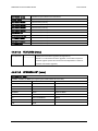
Errata A for MN-DMD2050E Rev 2
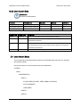
Comtech EF Data Documentation Update
Subject:
Errata Part Number:
PLM CO Number:
Comments:
Chapter 3, Theory of Operation
ER-DMD2050E-EA2
(Errata documents are not subject to revision.)
C-0028800
The new information will be included in the next released revision of the manual.
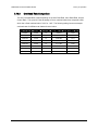
IMPORTANT
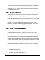
Set the modem to Loop Timing mode for these Loopback operations:
Tx/Rx Terrestrial Loopback
ER-DMD2050E-EA2
Tx/Rx Baseband Loopback
Rx Baseband Loopback
Rev -
PLM C-0028800
Blank Page
ER-DMD2050E-EA2
Rev -
PLM C-0028800
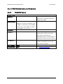
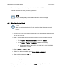
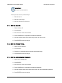
Errata B for MN-DMD2050E Rev 2
Comtech EF Data Documentation Update
Subject:
Errata Part Number:
PLM CO Number:
Comments:
ER-DMD2050E-EB2
Chapter 3 and Chapter 4 references to MN-DMDREMOTEOP manual
ER-DMD2050E-EB2
(Errata documents are not subject to revision.)
C-0028804
The new information will be included in the next released revision of the manual. See
the following pages.
Rev -
PLM C-0028804
DMD2050E Universal Satellite Modem
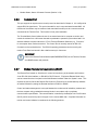
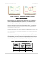
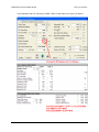
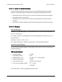
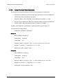
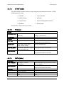
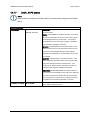
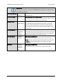
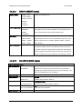
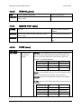
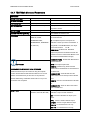
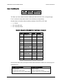
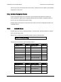
4.4.6.6
User Interfaces
SNMP (menu)
A description of OID organization is provided in the MN-DMDREMOTEOP manual.
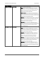
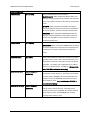
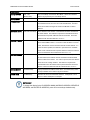
SNMP MENU
SNMP VERSION
{V1 & V2, V3}
This selection controls the SNMP Version that will be used in
messaging between the equipment and it’s host.
When V1 & V2 is used, RD COMMUNITY and RDWR
COMMUNITY are used to determine the authorization of an
incoming message.
When V3 is used, three contexts are supported: public, mib2, and
dev. Context, Authentication and Privacy are a portion of each
SNMPV3 message.
The public context will only allow the user to see the sysoid of the
unit. This is the most restricted access possible and only allows
the unit to be identified by a host SNMP Station.
The mib2 context allows a user with appropriate authentication to
access the mib2 OIDs and the SNMP OIDs. These are of interest
primarily to network operators not controlling the satellite link.
The dev context allows a user with appropriate authentication to
access the device control portion of the MIB. These OIDs are
used to control the devices satellite link and operation.
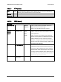
TRAP VERSION
{V1, V2}
This controls the type of message format used when a message
trap is generated by the equipment and bound for a SNMP Host.
Messages will only be sent if the unit has been authorized to do
so.
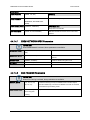
AUTHORIZATION
{TRAPS OFF, TRAPS
This controls the type of message format used when a message
ON}
trap is generated by the equipment and bound for a SNMP host.
Messages will only be sent if the unit has been authorized to do
so.
RD COMMUNITY
{16 characters of
This menu is only displayed when SNMP VERSION is set to V1 &
name}
V2. This is the community that a host must be acting within when
an OID variable is requested by a V1/V2 SNMP message.
RDWR COMMUNITY
{16 characters of
This menu is only displayed when SNMP VERSION is set to V1 &
name}
V2. This is the community that a host must be acting within when
an OID variable is being changed by a V1/V2 SNMP message.
TRAP AGENT
{XXX.XXX.XXX.XXX}
IP address of the device receiving SNMP Traps
Hexadecimal Mask
{ddd.ddd.ddd.ddd}
Decimal Mask
MN-DMD2050E Revision 2
4–31
DMD2050E Universal Satellite Modem
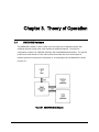
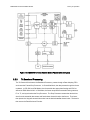
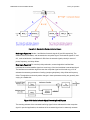
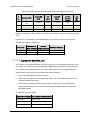
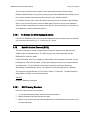
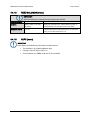
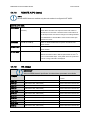
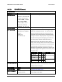
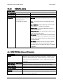
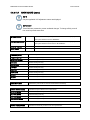
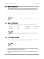
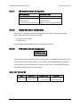
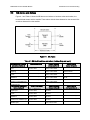
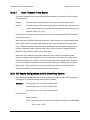
3.2.6
Theory of Operation
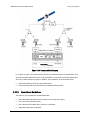
Modem Status, Alarms & Contact Closures (Section 3.2.9)
Terminal Port
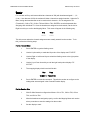
This port supports an asynchronous control protocol as described in Chapter 4. It is configured to
support RS-232 signal levels. This port is intended for use in computer-based remote M&C. All
functions of the modem may be monitored and controlled from this port via a common terminal
connected to the Terminal Port. This function is front panel selectable.
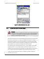
The Terminal Mode Control allows the use of an external terminal or computer to monitor and
control the modem from a full screen interactive presentation operated by the modem itself. No
external software is required other than VT-100 Terminal Emulation Software (e.g. “Procomm”
for a computer when used as a terminal. The Control Port is normally used as an RS–232
Connection to the terminal device. The RS-232 operating parameters can be set using the
modem Front Panel and stored in Non-volatile memory for future use.
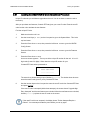
IMPORTANT
Refer to the Remote Protocol Manual (MN-DMDREMOTEOP) for the Terminal, Remote
and SNMP screens and protocols.
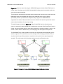
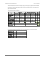
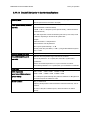
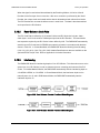
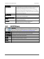
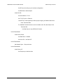
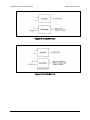
3.2.7
Modem Remote Communications (RLLP)
The Remote Port located on J20 allows for control and monitoring of parameters and functions
via an RS-232 Serial Interface, or RS-485 for RLLP Protocol. ‘Equipment Remote Mode’ setup
can be entered from the front panel or the Web Browser interface under the “System” menu. This
requires the user to first set the Remote Port Control to “Remote” then set the Multidrop Address
as needed followed by setting the Remote Interface to RS232 or RS485.
Control and status messages are conveyed between the modem and all subsidiary modems and
the host computer using packetized message blocks in accordance with a proprietary
communications specification. This communication is handled by the Radyne Link Level Protocol
(RLLP), which serves as a protocol ‘wrapper’ for the remote M&C data. See the MNDMDREMOTEOP manual for more information.
MN-DMD2050E Revision 2
3–8
Blank Page
ER-DMD2050E-EB2
Rev -
PLM C-0028804
Comtech EF Data is an
AS9100 Rev B / ISO9001:2000 Registered Company
DMD2050E
Universal Satellite Modem
Installation and Operation Manual
Part Number MN-DMD2050E
Revision 2
Copyright © Comtech EF Data, 2013. All rights reserved. Printed in the USA.
Comtech EF Data, 2114 West 7th Street, Tempe, Arizona 85281 USA, 480.333.2200, FAX: 480.333.2161
BLANK PAGE
DMD-2050E Universal Satellite Modem
Table of Contents
Revision 2
MN-DMD2050E
Table of Contents
PREFACE ................................................................................................................................. XIX
About this Manual.................................................................................................................................. xix
Cautions and Warnings .......................................................................................................................... xix
Patents and Trademarks ......................................................................................................................... xix
Related Documents ................................................................................................................................ xix
Electrical Safety ...................................................................................................................................... xx
Battery ..................................................................................................................................................... xx
Grounding ............................................................................................................................................... xx
Fuses ....................................................................................................................................................... xx
Telecommunications Terminal Equipment Directive ............................................................................. xx
Environmental ........................................................................................................................................ xxi
Low Voltage Directive (LVD) ............................................................................................................... xxi
EMC (Electromagnetic Compatibility) .................................................................................................. xxi
CE Mark ................................................................................................................................................ xxii
RoHS ..................................................................................................................................................... xxii
Product support ..................................................................................................................................... xxiii
On the web ........................................................................................................................................... xxiii
Return material authorization............................................................................................................... xxiii
Support business hours ........................................................................................................................ xxiii
After hours and weekends .................................................................................................................... xxiii
Comtech EF Data and Radyne support contacts .................................................................................. xxiii
Warranty Policy ..................................................................................................................................... xxiv
Limitations of Warranty ....................................................................................................................... xxiv
Exclusive Remedies ............................................................................................................................. xxiv
CHAPTER 1.
1.1
INTRODUCTION ............................................................................................. 1–1
Overview ...................................................................................................................................... 1–1
1.2
DMD2050E Configurations ........................................................................................................ 1–2
1.2.1
Features ................................................................................................................................. 1–2
1.2.2
Advanced Forward Error Correction and Modulation .......................................................... 1–3
1.2.3
Bandwidth Compression ....................................................................................................... 1–3
1.2.4
Interfaces ............................................................................................................................... 1–4
1.2.5
Remote Control and Monitoring ........................................................................................... 1–4
1.2.6
Compatibility ........................................................................................................................ 1–4
1.2.7
Physical Description ............................................................................................................. 1–4
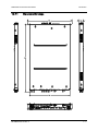
1.2.7.1 Dimensional Envelope ...................................................................................................... 1–5
1.3
Configurations and Options ....................................................................................................... 1–6
iii
DMD-2050E Universal Satellite Modem
Table of Contents
CHAPTER 2.
Revision 2
MN-DMD2050E
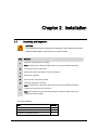
INSTALLATION .............................................................................................. 2–1
2.1
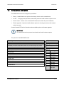
Unpacking and Inspection .......................................................................................................... 2–1
2.2
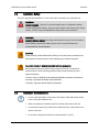
Installation Safety ....................................................................................................................... 2–2
2.3
Installation Considerations ........................................................................................................ 2–2
2.3.1
Location ................................................................................................................................ 2–3
2.3.2
Airflow .................................................................................................................................. 2–3
2.3.3
Temperature .......................................................................................................................... 2–3
2.3.4
Electrical Power .................................................................................................................... 2–3
2.3.5
Cables .................................................................................................................................... 2–4
2.4
Initial Configuration Check ....................................................................................................... 2–4
2.4.1
Standard Factory Configuration ............................................................................................ 2–4
2.5
Modulator Checkout ................................................................................................................... 2–5
2.5.1
Initial Start Up....................................................................................................................... 2–5
2.5.2
Factory Terminal Settings ..................................................................................................... 2–5
CHAPTER 3.
THEORY OF OPERATION ............................................................................. 3–1
3.1
DMD2050E Hardware ................................................................................................................ 3–1
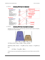
3.1.1
DMD2050E L-Band/IF Printed Circuit Card ........................................................................ 3–2
3.1.2
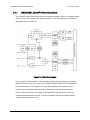
DMD2050E Baseband Processing Printed Circuit Card ....................................................... 3–3
3.1.3
Enhanced Interface Printed Circuit Card .............................................................................. 3–5
3.2
DMD2050E Functional Block Diagram .................................................................................... 3–5
3.2.1
Front Panel ............................................................................................................................ 3–5
3.2.2
Baseband Processing ............................................................................................................. 3–5
3.2.3
Tx Baseband Processing ....................................................................................................... 3–6
3.2.4
Rx Baseband Processing ....................................................................................................... 3–7
3.2.5
Monitor & Control (M&C) Subsystem ................................................................................. 3–7
3.2.6
Terminal Port ........................................................................................................................ 3–8
3.2.7
Modem Remote Communications (RLLP) ........................................................................... 3–8
3.2.8
Ethernet M&C Port ............................................................................................................... 3–9
3.2.9
Modem Monitor Status ......................................................................................................... 3–9
3.3
Internal Clock............................................................................................................................ 3–10
3.4
Loopback Features (Terrestrial & IF) .................................................................................... 3–10
3.5
DMD2050E Clocking Options.................................................................................................. 3–13
3.5.1
Clock Selection ................................................................................................................... 3–13
3.5.2
TX Clock Options ............................................................................................................... 3–14
3.5.2.1 SCTE: Serial Clock Transmit External ........................................................................... 3–15
3.5.2.2 SCT: Serial Clock Transmit ............................................................................................ 3–15
3.5.3
RX Buffer Clock Options ................................................................................................... 3–16
3.5.3.1 RX SAT Clock ................................................................................................................ 3–16
3.5.3.2 SCTE: Serial Clock Transmit External ........................................................................... 3–16
iv
DMD-2050E Universal Satellite Modem
Table of Contents
Revision 2
MN-DMD2050E
3.5.3.3 SCT: Serial Clock Transmit ............................................................................................ 3–17
3.5.3.4 EXT CLK/EXT BNC: External Clock, J16 .................................................................... 3–17
3.5.3.5 EXT IDI: Insert Data In .................................................................................................. 3–17
3.5.4
EXT REF: External Reference, Top BNC Port, J10 ........................................................... 3–17
3.6
Transmit Timing Options ......................................................................................................... 3–18
3.6.1
MIL-188-114A, RS-422 (TX Clock Source - SCT or SCTE) ............................................ 3–18
3.6.2
G.703 Interface ................................................................................................................... 3–18
3.6.3
HSSI Interface ..................................................................................................................... 3–18
3.6.4
Ethernet Data Interface (Optional) ...................................................................................... 3–19
3.7
Receive Timing Options............................................................................................................ 3–19
3.7.1
Loop Timing ....................................................................................................................... 3–19
3.7.2
Transmit (MIL-188-114A, RS-422) ................................................................................... 3–19
3.7.3
G.703 Interface or Asymmetrical Data Rates ..................................................................... 3–19
3.7.4
Receive ................................................................................................................................ 3–19
3.8
Ebem Framing Unit .................................................................................................................. 3–20
3.8.1
DMD2050E Information Throughput Adpatation (ITA) .................................................... 3–20
3.8.2
Embedded Channel ............................................................................................................. 3–20
3.9
STANAG Turbo Coding........................................................................................................... 3–20
3.10 FIPs TRANSEC Module .......................................................................................................... 3–21
3.10.1
Traffic Encryption and Decryption Keys and Key Generation ........................................... 3–21
3.10.1.1
Key Agreement ........................................................................................................... 3–21
3.10.1.2
Key Agreement Algorithm.......................................................................................... 3–24
3.10.1.2.1 Key Derivation ........................................................................................................ 3–24
3.10.1.3
Accessing Encryption/Decryption Features ................................................................ 3–24
3.10.1.4
Enabling Encryption from the Front Panel ................................................................. 3–24
3.11 DoubleTalk Carrier-in-Carrier Option .................................................................................. 3–26
3.11.1
What is DoubleTalk Carrier-in-Carrier? ............................................................................. 3–27
3.11.2
Application Requirements................................................................................................... 3–27
3.11.3
Operational Guidelines ....................................................................................................... 3–29
3.11.4
System Functionality and Operational Considerations ....................................................... 3–30
3.11.5
DoubleTalk Carrier-in-Carrier Cancellation Process .......................................................... 3–33
3.11.6
Margin Requirements .......................................................................................................... 3–35
3.11.7
Carrier-in-Carrier Latency .................................................................................................. 3–35
3.11.8
Carrier-in-Carrier and Adaptive Coding and Modulation ................................................... 3–35
3.11.9
Carrier-in-Carrier Link Design ........................................................................................... 3–35
3.11.9.1
Symmetric Data Rate Link .......................................................................................... 3–36
3.11.9.2
Asymmetric Data Rate Link ....................................................................................... 3–39
3.11.9.3
Power Limited Links ................................................................................................... 3–41
3.11.10
Carrier-in-Carrier Commissioning and Deployment....................................................... 3–42
3.11.11
Validating Carrier-in-Carrier Performance ..................................................................... 3–44
3.11.12
Operational References ................................................................................................... 3–45
3.11.12.1 Carrier-in-Carrier Link Budget Calculation ................................................................ 3–45
3.11.12.2 Estimating PSD Ratio ................................................................................................. 3–46
3.11.12.3 Estimating PSD Ratio from LST................................................................................. 3–46
v
DMD-2050E Universal Satellite Modem
Table of Contents
Revision 2
MN-DMD2050E
3.11.12.4 Estimating PSD Ratio from Satmaster ........................................................................ 3–47
3.11.12.5 Estimating PSD Ratio Using Spectrum Analyzer ....................................................... 3–47
3.11.13
DoubleTalk Carrier-in-Carrier Specifications................................................................. 3–48
3.11.14
Carrier-in-Carrier Summary ............................................................................................ 3–49
3.11.15
Glossary .......................................................................................................................... 3–49
3.12 TPC and Low Density Parity Check (LDPC) Coding ........................................................... 3–51
3.12.1
LDPC versus TPC ............................................................................................................... 3–52
3.12.2
TPC and LDPC Summary ................................................................................................... 3–56
3.13 Reed-Solomon Codec ................................................................................................................ 3–56
3.13.1
Reed-Solomon Operation in the DMD2050E ..................................................................... 3–56
3.13.2
Reed-Solomon Code Rate ................................................................................................... 3–57
3.13.3
Interleaving ......................................................................................................................... 3–57
3.14
DMD2050E Automatic Uplink Power Control (AUPC Operation) ..................................... 3–58
3.15
Asynchronous Overhead Operation (Async Port / ES-ES Communications) ..................... 3–58
3.16
Standard IBS Mode .................................................................................................................. 3–60
3.17
Asynchronous Multiplexer Mode ........................................................................................... 3–61
3.18 ESC Backward Alarms............................................................................................................. 3–61
3.18.1
To Disable the ESC Backward Alarms ............................................................................... 3–62
3.19 Satellite Control Channel (SCC) ............................................................................................. 3–62
3.19.1
SCC Framing Structure ....................................................................................................... 3–62
3.19.2
Aggregate Data Rate ........................................................................................................... 3–64
3.19.3
Overhead Rate Comparison ................................................................................................ 3–65
3.19.4
Actual Overhead Rate Calculation ...................................................................................... 3–66
3.20
SCC OVERHEAD CHANNEL SETUP .................................................................................. 3–67
3.21
Locating the DMD2050E ID Code Operational Procedure .................................................. 3–69
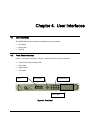
CHAPTER 4.
4.1
USER INTERFACES ....................................................................................... 4–1
User Interfaces ............................................................................................................................ 4–1
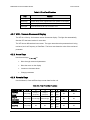
4.2
Front Panel Interface .................................................................................................................. 4–1
4.2.1
VFD - Vacuum Fluorescent Display ..................................................................................... 4–2
4.2.2
Arrow Keys ........................................................................................................................... 4–2
4.2.3
Numeric Keys ....................................................................................................................... 4–2
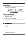
4.2.4
LED Lights............................................................................................................................ 4–3
4.3
Parameter Setup.......................................................................................................................... 4–4
4.3.1
Select a Parameter ................................................................................................................. 4–4
4.3.2
Enter and Save a New Parameter .......................................................................................... 4–4
4.3.3
Change a New Parameter Before Saving .............................................................................. 4–4
vi
DMD-2050E Universal Satellite Modem
Table of Contents
Revision 2
MN-DMD2050E
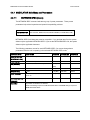
4.4
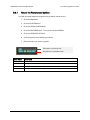
Front Panel Main Menus............................................................................................................ 4–4
4.4.1
MODULATOR Main Menu and Parameters ........................................................................ 4–5
4.4.1.1 NETWORK SPEC (menu)................................................................................................ 4–5
4.4.1.2 STRAP CODE .................................................................................................................. 4–6
4.4.1.3 IF (menu) .......................................................................................................................... 4–6
4.4.1.4 DATA (menu) ................................................................................................................... 4–6
4.4.1.4.1 EBEM NETWORK SPEC Parameters ....................................................................... 4–8
4.4.1.4.2 SCC FRAMING Parameters ....................................................................................... 4–8
4.4.1.5 REED-SOLOMON (menu)............................................................................................... 4–9
4.4.1.6 AUPC (menu) ................................................................................................................... 4–9
4.4.1.7 LOCAL AUPC (menu) ................................................................................................... 4–10
4.4.1.8 REMOTE AUPC (menu) ................................................................................................ 4–13
4.4.1.9 ITA (menu) ..................................................................................................................... 4–13
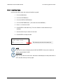
4.4.2
DEMODULATOR Main Menu and Parameters................................................................. 4–14
4.4.2.1 NETWORK SPEC (menu).............................................................................................. 4–14
4.4.2.2 STRAP CODE ................................................................................................................ 4–15
4.4.2.3 IF (menu) ........................................................................................................................ 4–15
4.4.2.4 DATA (menu) ................................................................................................................. 4–16
4.4.2.5 REED-SOLOMON (menu)............................................................................................. 4–17
4.4.2.6 CNC (menu) .................................................................................................................... 4–18
4.4.2.7 ITA (menu) ..................................................................................................................... 4–18
4.4.3
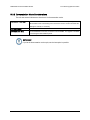
INTERFACE Main Menu and Parameters ......................................................................... 4–19
4.4.3.1 TX SETUP (menu).......................................................................................................... 4–19
4.4.3.1.1 DROP & INSERT (menu) ........................................................................................ 4–21
4.4.3.1.2 TX ASYNC MODE (menu) ..................................................................................... 4–21
4.4.3.2 RX SETUP (menu) ......................................................................................................... 4–22
4.4.3.2.1 DROP & INSERT (menu) ........................................................................................ 4–23
4.4.3.2.2 RX ASYNC MODE (menu) ..................................................................................... 4–23
4.4.3.3 GENERAL (menu) ......................................................................................................... 4–24
4.4.4
MONITOR Main Menu and Parameters ............................................................................. 4–24
4.4.4.1 LINK STATUS (menu) .................................................................................................. 4–25
4.4.4.2 VOLTAGES (menu) ....................................................................................................... 4–27
4.4.4.3 CnC (menu) ..................................................................................................................... 4–27
4.4.4.4 ITA (menu) ..................................................................................................................... 4–27
4.4.5
ALARMS Main Menu and Parameters ............................................................................... 4–28
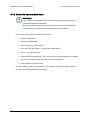
4.4.6
SYSTEM Main Menu and Parameters ................................................................................ 4–28
4.4.6.1 FRONT PANEL (menu) ................................................................................................. 4–28
4.4.6.2 REMOTE CONTROL .................................................................................................... 4–28
4.4.6.3 TERMINAL (menu) ....................................................................................................... 4–29
4.4.6.4 REMOTE PORT (menu) ................................................................................................ 4–29
4.4.6.5 TCP/IP (menu) ................................................................................................................ 4–29
4.4.6.6 SNMP (menu) ................................................................................................................. 4–31
4.4.6.7 FTP (menu) ..................................................................................................................... 4–32
4.4.6.8 WEB (menu) ................................................................................................................... 4–32
4.4.6.9 TRANSEC (menu) .......................................................................................................... 4–33
4.4.6.10
HW/FW CONFIG (menu) .......................................................................................... 4–33
4.4.6.10.1 MAIN BOARD (menu) .......................................................................................... 4–34
4.4.6.10.2 FEATURES (menu) ................................................................................................ 4–35
4.4.6.10.3 UPGRADE LIST (menu) ........................................................................................ 4–35
4.4.7
TEST Main Menu and Parameters ...................................................................................... 4–36
vii
DMD-2050E Universal Satellite Modem
Table of Contents
Revision 2
MN-DMD2050E
4.5
Terminal Mode Control............................................................................................................ 4–38
4.5.1
Terminal Mode Screens ...................................................................................................... 4–38
4.5.2
Terminal Mode Operations ................................................................................................. 4–38
4.5.3
Setup for Terminal Mode .................................................................................................... 4–39
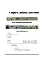
CHAPTER 5.
EXTERNAL CONNECTIONS .......................................................................... 5–1
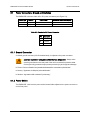
5.1
Power Connectors, Ground and Switches ................................................................................ 5–2
5.1.1
Ground Connector ................................................................................................................. 5–2
5.1.2
Power Switch ........................................................................................................................ 5–2
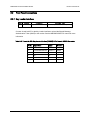
5.2
Front Panel Connections ............................................................................................................ 5–3
5.2.1
Key Loader Interface ............................................................................................................ 5–3
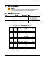
5.3
Rear Panel Connectors ............................................................................................................... 5–4
5.3.1
HSSI / Ethernet Connectors .................................................................................................. 5–4
5.3.2
EXT REF (J10) ..................................................................................................................... 5–5
5.3.3
IF Connectors (Transmit and Receive) J11, J12, J13, J14 .................................................... 5–5
5.3.4
ALARM (J15) ....................................................................................................................... 5–6
5.3.4.1 IBS Network Alarms Configuration ................................................................................. 5–7
5.3.4.2 Closed Net Alarms Configuration..................................................................................... 5–7
5.3.4.3 RTS Carrier Alarms Configuration ................................................................................... 5–7
5.3.5
EXT CLK (J16)..................................................................................................................... 5–7
5.3.6
ASYNC (J17) ........................................................................................................................ 5–8
5.3.7
ANT. HANDOVER (J18) (Future Option) ........................................................................... 5–8
5.3.8
MIL-188-114A (J19)............................................................................................................. 5–9
5.3.9
Monitor and Control Connectors J20, J21 .......................................................................... 5–10
CHAPTER 6.
MAINTENANCE AND TROUBLESHOOTING ................................................ 6–1
6.1
Periodic Maintenance ................................................................................................................. 6–1
6.1.1
Battery Replacement ............................................................................................................. 6–1
6.1.2
Clock Adjustment ................................................................................................................. 6–1
6.1.3
Fuse Replacement ................................................................................................................. 6–1
6.2
Troubleshooting .......................................................................................................................... 6–2
6.2.1
Basic Troubleshooting Procedures........................................................................................ 6–2
6.2.2
Troubleshooting Symptoms and Causes ............................................................................... 6–2
6.2.2.1 Symptom: The modem does not acquire the incoming carrier. ....................................... 6–2
6.2.2.2 Symptom: The ASYNC port is not configured correctly................................................. 6–2
6.3
Alarms .......................................................................................................................................... 6–3
6.3.1
Major Transmit Alarms ......................................................................................................... 6–3
6.3.2
Major Rx Alarms .................................................................................................................. 6–3
6.3.3
Minor Tx Alarms .................................................................................................................. 6–4
6.3.3.1 Minor Rx Alarms .............................................................................................................. 6–5
6.3.3.2 Drop and Insert Alarms ..................................................................................................... 6–6
6.3.3.3 Common Major Alarms .................................................................................................... 6–6
viii
DMD-2050E Universal Satellite Modem
Table of Contents
Revision 2
MN-DMD2050E
6.4
Alarm Masks ............................................................................................................................... 6–8
6.4.1
Active Alarms ....................................................................................................................... 6–8
6.4.1.1 Major Alarms .................................................................................................................... 6–8
6.4.1.2 Minor Alarms .................................................................................................................... 6–8
6.4.2
Common Equipment Alarms ................................................................................................ 6–9
6.4.3
Latched Alarms ..................................................................................................................... 6–9
6.4.4
Backward Alarms ................................................................................................................ 6–11
6.5
IBS Alarms and Actions ........................................................................................................... 6–12
CHAPTER 7.
TECHNICAL SPECIFICATIONS ..................................................................... 7–1
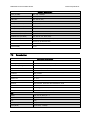
7.1
Modulator .................................................................................................................................... 7–1
7.2
Demodulator ................................................................................................................................ 7–2
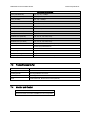
7.3
Plesiochronous Buffer ................................................................................................................. 7–3
7.4
Monitor and Control................................................................................................................... 7–3
7.5
Terrestrial Interfaces .................................................................................................................. 7–4
7.6
IBS/Synchronous Interface (Standard) ..................................................................................... 7–4
7.7
High-Speed Serial Interface (HSSI) & Gigi Ethernet Data Interface .................................... 7–4
7.8
Key loader interface .................................................................................................................... 7–4
7.9
Environmental ............................................................................................................................. 7–4
7.10
Physical ........................................................................................................................................ 7–4
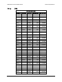
7.11 Data Rate Limits ......................................................................................................................... 7–5
7.11.1
Non-DVB .............................................................................................................................. 7–5
7.11.2
DVB ...................................................................................................................................... 7–7
7.12 BER Specifications ...................................................................................................................... 7–9
7.12.1
BER Performance (Viterbi) .................................................................................................. 7–9
7.12.2
BER Performance (Sequential) ........................................................................................... 7–10
7.12.3
BER Performance (Viterbi with Reed-Solomon) ............................................................... 7–11
7.12.4
BER Performance (Turbo) .................................................................................................. 7–12
7.12.5
BER Performance (8PSK Trellis) ....................................................................................... 7–13
7.12.6
BER Performance (8PSK Turbo) ........................................................................................ 7–14
7.12.7
BER Performance (16QAM Viterbi) .................................................................................. 7–15
7.12.8
BER Performance (16QAM Viterbi with Reed-Solomon) ................................................. 7–16
7.12.9
BER Performance (16QAM Turbo) .................................................................................... 7–17
7.12.10
BER Performance (OQPSK Turbo) ................................................................................ 7–18
7.12.11
BER Performance (BPSK Turbo) ................................................................................... 7–19
7.12.12
BER Performance (8PSK Turbo) .................................................................................... 7–20
7.12.13
BER Performance (16QAM Turbo) ................................................................................ 7–21
ix
DMD-2050E Universal Satellite Modem
Table of Contents
7.12.14
7.12.15
7.12.16
7.12.17
7.12.18
7.12.19
7.13
Revision 2
MN-DMD2050E
B/O/QPSK BER Performance (LDPC) ........................................................................... 7–22
8PSK / 8QAM BER Performance (LDPC) ..................................................................... 7–23
16QAM BER Performance (LDPC) ............................................................................... 7–24
BER Performance B/O/QPSK (MILSTD 188-165B or STANAG) Turbo ..................... 7–25
BER Performance 8-PSK (MILSTD 188-165B or STANAG) Turbo ............................ 7–26
BER Performance 16APSK (MILSTD 188-165B or STANAG) Turbo......................... 7–27
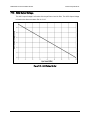
AGC Output Voltage ................................................................................................................ 7–34
APPENDIX A. PRODUCT OPTIONS.................................................................................... A–1
A.1
Hardware Options ..................................................................................................................... A–1
A.2
Custom Options .......................................................................................................................... A–1
APPENDIX B.
FRONT PANEL UPGRADES AND DEMONSTRATION MODE .................. B–1
B.1
Introduction ................................................................................................................................ B–1
B.2
Required Equipment ................................................................................................................. B–1
B.3
Procedures .................................................................................................................................. B–1
B.3.1
Record the Features and Options ......................................................................................... B–2
B.3.2
Record the Unit ID ............................................................................................................... B–3
B.3.3
Order the Demonstration or the Upgrade ............................................................................. B–3
B.3.4
Install the Code .................................................................................................................... B–4
B.3.5
Demonstration Mode Considerations................................................................................... B–5
B.3.6
Cancel the Demonstration Mode.......................................................................................... B–6
APPENDIX C.
CARRIER CONTROL ................................................................................... C–1
C.1
Carrier Control and Alarms ..................................................................................................... C–1
C.2
Carrier States and Changes to Programming ......................................................................... C–1
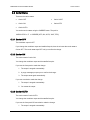
C.3
Carrier States ............................................................................................................................. C–2
C.3.1
Carrier OFF .......................................................................................................................... C–2
C.3.2
Carrier ON ........................................................................................................................... C–2
C.3.3
Carrier AUTO ...................................................................................................................... C–2
C.3.4
Carrier VSAT ....................................................................................................................... C–3
C.3.5
CARRIER RTS .................................................................................................................... C–3
APPENDIX D.
D.1
WEB INTERFACE SETUP GUIDE .............................................................. D–1
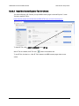
Introduction ................................................................................................................................ D–1
D.2
Setup ............................................................................................................................................ D–1
D.2.1
TCP-IP Menus ..................................................................................................................... D–1
x
DMD-2050E Universal Satellite Modem
Table of Contents
D.2.2
Revision 2
MN-DMD2050E
IP Address ............................................................................................................................ D–2
D.3
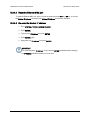
Web Interface Security .............................................................................................................. D–2
D.3.1
Default User Accounts ......................................................................................................... D–2
D.3.2
User Account Data ............................................................................................................... D–3
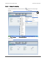
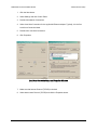
D.1
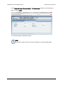
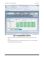
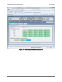
User Account Setup ................................................................................................................. D–3
D.1.1
Edit the User ID. .................................................................................................................. D–4
D.1.2
Edit the Access Group.......................................................................................................... D–4
D.1.3
Edit the Authentication Password. ....................................................................................... D–4
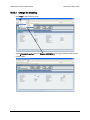
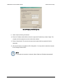
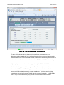
D.2
Reset a User Account ................................................................................................................. D–5
D.3
Confirmation .............................................................................................................................. D–5
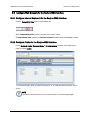
D.4
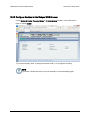
Equipment Website .................................................................................................................... D–6
D.4.1
Log in to the Equipment Website ........................................................................................ D–7
D.5
Web Page Appearance ............................................................................................................... D–8
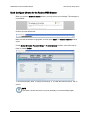
D.6
Configure Web Browsers for the Radyne WEB Interface ..................................................... D–9
D.6.1
Configure Internet Explorer 9 for the Radyne WEB Interface ............................................ D–9
D.6.2
Configure Firefox for the Radyne WEB Interface ............................................................... D–9
D.6.2.1 Change the encoding: ..................................................................................................... D–10
D.6.2.2 Install the Internet Explorer Tab V2 add-on .................................................................. D–11
D.6.3
Configure Chrome for the Radyne WEB Browser ............................................................ D–12
D.6.3.1 Change the encoding ...................................................................................................... D–13
D.6.3.2 Install the Internet Explorer Tab for Chrome ................................................................. D–14
D.6.4
Configure Safari for the Radyne WEB Browser ................................................................ D–15
D.6.4.1 Empty the browser cache ............................................................................................... D–15
D.6.4.2 Reset the Ethernet M&C port......................................................................................... D–16
D.6.4.3 Re-enter the Modem IP address ..................................................................................... D–16
D.6.4.4 Change the encoding ...................................................................................................... D–18
D.6.5
Configure Maxthon for the Radyne WEB Browser ........................................................... D–19
D.6.5.1 Change the browser mode .............................................................................................. D–20
D.6.5.2 Change the encoding ...................................................................................................... D–21
APPENDIX E.
DROP AND INSERT
(STANDARD AND EFFICIENT OPTIONS) ............. E–1
E.1
Introduction ................................................................................................................................ E–1
E.2
System Requirements ................................................................................................................ E–1
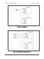
E.3
Configuration Examples ............................................................................................................ E–2
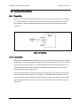
E.4
Functional Descriptions ............................................................................................................. E–4
E.4.1
Drop Only ............................................................................................................................. E–4
E.4.2
Insert Only ............................................................................................................................ E–4
E.4.3
Data Formats ......................................................................................................................... E–6
E.4.3.1 PCM-30 ............................................................................................................................. E–6
E.4.3.2 PCM-30C .......................................................................................................................... E–6
xi
DMD-2050E Universal Satellite Modem
Table of Contents
Revision 2
MN-DMD2050E
E.4.3.3 PCM-31 ............................................................................................................................. E–6
E.4.3.4 PCM-31C .......................................................................................................................... E–7
E.4.3.5 T1-D4/T1-D4-S................................................................................................................. E–7
E.4.3.6 T1-ESF/T1-ESF-S............................................................................................................. E–7
E.4.4
Systems with Multiple Destinations ..................................................................................... E–7
E.4.5
Drop and Insert Mapping ...................................................................................................... E–7
E.5
Configuring the Modem for Drop and Insert ........................................................................ E–10
E.5.1
Data Rate ............................................................................................................................. E–11
E.5.2
Operational Network Specification ..................................................................................... E–12
E.5.3
Terrestrial Framing - Drop Mode/Insert Mode ................................................................... E–12
E.5.3.1 Insert Terrestrial Frame Source....................................................................................... E–13
E.5.4
D&I Sample Configurations and D&I Clock Setup Options .............................................. E–13
E.5.4.1 D&I Clock Setup Examples ............................................................................................ E–17
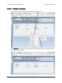
E.6
D&I Maps and Map Editing ................................................................................................... E–19
E.7
Efficient Drop and Insert Introduction .................................................................................. E–23
E.8
Prerequisite ............................................................................................................................... E–24
E.9
Efficient Drop and Insert Mode .............................................................................................. E–25
E.9.1
Calculating the Required Satellite Bandwidth .................................................................... E–26
E.9.2
Calculating the Basic Efficient D&I Rate ........................................................................... E–26
E.9.3
Calculating the Efficient D&I Rate with E1 Signaling ....................................................... E–26
E.9.4
Calculating the Efficient D&I Rate with Enhanced Asynchronous Overhead ...................E–27
APPENDIX F.
TCP/IP ETHERNET SETUP ...........................................................................F–1
F.1
Introduction ................................................................................................................................. F–1
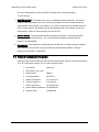
F.2
TCP/IP Network Configuration ................................................................................................ F–1
F.3
Network Configuration Summary ............................................................................................. F–3
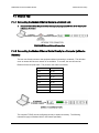
F.4
Ethernet Test ............................................................................................................................... F–4
F.4.1
Connecting the Modem Ethernet Cable to a Network Link .................................................. F–4
F.4.2
Connecting the Modem Ethernet Cable Directly to a Computer (without a Network) ......... F–4
F.5
Testing the Ethernet Connection using the Ping Program (Optional) ...................................F–7
APPENDIX G.
AUPC OPERATION ...................................................................................... G–1
G.1 Automatic Uplink Power Control (AUPC Operation) ........................................................... G–1
Radyne AUPC ...................................................................................................................... G–1
G.1.1
G.1.2
EF AUPC ............................................................................................................................. G–2
G.1.3
Near Side AUPC .................................................................................................................. G–2
G.1.4
EBEM AUPC ....................................................................................................................... G–3
xii
DMD-2050E Universal Satellite Modem
Table of Contents
APPENDIX H.
Revision 2
MN-DMD2050E
ETHERNET DATA INTERFACE SETUP...................................................... H–1
H.1 Configuring the modem to use the Ethernet Data Interface (Optional) ............................... H–1
H.1.1
Ethernet Flow Control.......................................................................................................... H–2
H.1.1.1 Half-Duplex Flow Control ............................................................................................... H–2
H.1.1.2 Full-Duplex Flow Control ................................................................................................ H–2
H.1.2
Ethernet Daisy Chain ........................................................................................................... H–2
H.1.3
Ethernet QOS Type .............................................................................................................. H–3
H.1.4
Ethernet QOS Queue............................................................................................................ H–3
H.1.5
Setting Up The DMD2050E Ethernet Bridge To Operate Like A FIFO ............................. H–4
H.1.6
Packet Statistics ................................................................................................................... H–5
APPENDIX I.
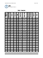
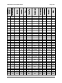
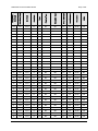
STRAP CODES ................................................................................................ I–1
I.1
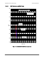
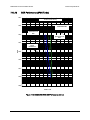
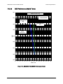
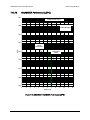
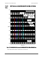
Strap Codes.................................................................................................................................. I–1
I.1.1 An example of how to set a strap code ...................................................................................... I–1
I.2
Sample Applications ................................................................................................................... I–6
I.2.1 Operational Case Examples ....................................................................................................... I–7
I.2.1.1 Case 1: IDR 8.448 Mbps, 3/4 Rate Viterbi ....................................................................... I–7
I.2.1.2 Case 2: IBS 1.544 Mbps, 3/4 Rate Viterbi ........................................................................ I–9
I.2.1.3 Case 3: Closed Network, 3/4 Rate Viterbi, IBS Overhead ............................................. I–11
I.2.1.4 Case 4: Loop Timing Example ....................................................................................... I–13
APPENDIX J.
ITA OPERATION ............................................................................................ J–1
J.1
Information Throughput Adaptation (ITA Operation) .......................................................... J–1
J.1.1 Properties of ITA on the DMD2050E: ...................................................................................... J–2
J.1.2 Basic Setup (Example) .............................................................................................................. J–3
J.1.2.1 Initial DMD2050E Modem Setup ..................................................................................... J–4
ADDENDUM: TRANSEC MODULE LICENSED SOFTWARE
xiii
DMD-2050E Universal Satellite Modem
Table of Contents
Revision 2
MN-DMD2050E
Tables
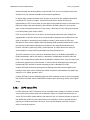
Table 3-1. Spectral Efficiency using DoubleTalk Carrier-in-Carrier ........................................................ 3–32
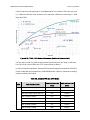
Table 3-2. Available TPC and LDPC Modes........................................................................................... 3–53
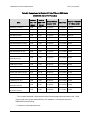
Table 3-3. Comparison of all Comtech EF Data TPC and LDPC Modes (DMD2050E with LDPC/TPC
Codec) ............................................................................................................................................. 3–55
Table 3-4. Reed-Solomon Codes ........................................................................................................... 3–58
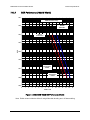
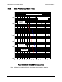
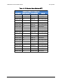
Table 3-5. Baud Rate Examples ............................................................................................................. 3–59
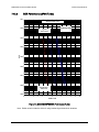
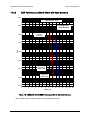
Table 3-6. Bits of Overhead Housekeeping Byte 32 ............................................................................... 3–60
Table 4-1. Front Panel Functions .............................................................................................................. 4–2
Table 4-2. Front Panel Key Functions ...................................................................................................... 4–2
Table 4-3. Front Panel LED Lights ............................................................................................................ 4–3
Table 5-2. Pinouts for DC Power Connector............................................................................................. 5–2
Table 5-1. Pinouts for SKL Key Loader Interface (RS-232) 6-Pin Female GC283 Connector ................. 5–3
Table 5-7. Pinouts for J1 HSSI 50-Pin SCSI-2 Connector........................................................................ 5–4
Table 5-3. Pinouts for J15 ALARM Port 15-pin Female D Connector ...................................................... 5–6
Table 5-4. Pinouts for J17 ASYNC Port 9-pin Female D Connector ........................................................ 5–8
Table 5-5. Pinouts for J19 MIL-188-114A Port 25-pin Female D Connector ............................................ 5–9
Table 5-6. Pinouts for J20 REMOTE Port (RS-485 or RS-232) 9-pin Female D Connector .................. 5–10
Table 6-1. IBS Fault Conditions and Actions (includes Drop and Insert) ............................................... 6–12
Table E-1. D&I Multiplexer Map Locations Used ...................................................................................E–19
Table E-2. D&I ROM Maps ....................................................................................................................E–20
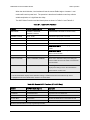
Table G-1. Local AUPC Functions .......................................................................................................... G–4
Table G-2. Remote AUPC Functions (EF AUPC Only) ........................................................................... G–4
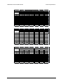
Table I-1. Strap Codes .............................................................................................................................. I–2
Table J-1 - ITA Waveforms and Selection ................................................................................................ J–3
Table J-2 - Initial Modem Setup ................................................................................................................ J–4
Table J-3 - ITA Setup .............................................................................................................................. J–11
Table J-4. Transmit ITA Functions ......................................................................................................... J–12
Table J-5. Receive ITA Functions ........................................................................................................... J–13
Table J-6 – ITA Waveform Masks (Modulator UUT) ............................................................................... J–14
Table J-7 – ITA Waveform Masks (Demodulator UUT) .......................................................................... J–15
Table J-8 – ITA Waveform Masks (Reference Modulator) ..................................................................... J–16
Table J-9 – ITA Waveform Masks (Reference Demodulator) ................................................................. J–17
xiv
DMD-2050E Universal Satellite Modem
Table of Contents
Revision 2
MN-DMD2050E
Figures
Figure 1-1. DMD2050E Universal Satellite Modem Front Panel ............................................................. 1–1
Figure 3-1. DMD2050E Block Diagram..................................................................................................... 3–1
Figure 3-2. IF Card Block Diagram ........................................................................................................... 3–2
Figure 3-3. DMD2050E Baseband Processing Card Block Diagram ....................................................... 3–4
Figure 3-4. DMD2050E Universal Satellite Modem Functional Block Diagram ........................................ 3–6
Figure 3-5. Loopback Functional Block Diagram .................................................................................... 3–11
Figure 3-6. Loopback Functional Block Diagram .................................................................................... 3–12
Figure 3-7. Loopback Functional Block Diagram .................................................................................... 3–13
Figure 3-8. Clocking and Polarity Diagram ............................................................................................. 3–14
Figure 3-9. Traffic Encryption Key Negotiation ....................................................................................... 3–22
Figure 3-10. Traffic Decryption Key Negotiation ..................................................................................... 3–23
Figure 3-11. TRANSEC Secure Web Browser Configuration Page ....................................................... 3–25
Figure 3-12. DMD2050E Handheld Key Loader ..................................................................................... 3–26
Figure 3-13. Conceptual Block Diagram ................................................................................................. 3–29
Figure 3-14. Conventional FDMA Link .................................................................................................... 3–30
Figure 3-15. Same Link Using DMD2050E and DoubleTalk Carrier-in-Carrier ..................................... 3–31
Figure 3-16. Duplex Link Optimization .................................................................................................... 3–32
Figure 3-17. DoubleTalk Carrier-in-Carrier Signals ................................................................................ 3–34
Figure 3-18. Carrier-in-Carrier Signal Processing Block Diagram .......................................................... 3–34
Figure 3-19. TPC & LDPC Modes Performance (Relative to Shannon Limit) ........................................ 3–53
Figure 3-20. Reed-Solomon Encoder Functional Block Diagram ........................................................... 3–57
Figure 3-21. Reed-Solomon Decoder Functional Block Diagram ........................................................... 3–57
Figure 3-22. 1 to 3 Control Ratio ............................................................................................................. 3–63
Figure 3-23. 1 to 1 Control Ratio ............................................................................................................. 3–63
Figure 4-1. Front Panel ............................................................................................................................. 4–1
Figure 4-2. Enter New Parameters .......................................................................................................... 4–4
Figure 5-1. DMD2050E Universal Satellite Modem Front Panel .............................................................. 5–1
Figure 5-2. DMD2050E Rear Panel .......................................................................................................... 5–1
Figure 5-3. DMD2050E Rear Panel Configurations .................................................................................. 5–1
Figure 6-1. IBS Alarms ........................................................................................................................... 6–12
Figure 7-1. DMD2050E B/O/QPSK BER Performance (Viterbi) ............................................................... 7–9
Figure 7-2. DMD2050E B/O/QPSK BER Performance (Sequential) ...................................................... 7–10
Figure 7-3. DMD2050E B/O/QPSK BER Performance (Viterbi with Reed-Solomon) ............................ 7–11
Figure 7-4. DMD2050E B/O/QPSK BER Performance (Turbo) .............................................................. 7–12
Figure 7-5. DMD2050E 8PSK BER Performance (Trellis)...................................................................... 7–13
Figure 7-6. DMD2050E 8PSK BER Performance (Turbo) ...................................................................... 7–14
Figure 7-7. DMD2050E 16QAM BER Performance (Viterbi) .................................................................. 7–15
Figure 7-8. DMD2050E 16QAM BER Performance (Viterbi with Reed-Solomon) ................................. 7–16
Figure 7-9. DMD2050E 16QAM BER Performance (Turbo) ................................................................... 7–17
Figure 7-10. DMD2050E OQPSK BER Performance (Turbo) ................................................................ 7–18
Figure 7-11. DMD2050E BPSK BER Performance (Turbo) ................................................................... 7–19
Figure 7-9. DMD2050E 8PSK BER Performance (Turbo) ...................................................................... 7–20
Figure 7-13. DMD2050E 16QAM BER Performance (Turbo) ................................................................. 7–21
Figure 7-14. DMD2050E B/O/QPSK BER Performance (LDPC)............................................................ 7–22
Figure 7-15. DMD2050E 8PSK / 8QAM BER Performance (LDPC) ...................................................... 7–23
Figure 7-16. DMD2050E 16QAM BER Performance (LDPC)................................................................. 7–24
Figure 7-17. DMD2050E BER Performance B/O/QPSK (MILSTD 188-165B or STANAG) Turbo......... 7–25
Figure 7-18. DMD2050E BER Performance 8-PSK (MILSTD 188-165B or STANAG) Turbo ............... 7–26
Figure 7-16. DMD2050E BER Performance 16APSK (MILSTD 188-165B or STANAG) ....................... 7–27
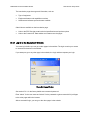
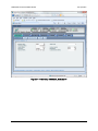
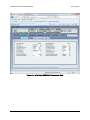
Figure D-1. WEB Browser Equipment Introduction Page ........................................................................ D–6
Figure D-2. Login Window........................................................................................................................ D–7
xv
DMD-2050E Universal Satellite Modem
Table of Contents
Revision 2
MN-DMD2050E
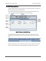
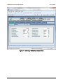
Figure D-3. Monitor and Control Web Page............................................................................................. D–8
Figure E-1. Looped Modems ...................................................................................................................E–3
Figure E-2 Looped Modems with Separate D&I Trunks ..........................................................................E–3
Figure E-3 Drop Only ...............................................................................................................................E–4
Figure E-4 Insert Only with Eternal Frame Source ..................................................................................E–5
Figure E-5 Insert Only with Internal Frame Source .................................................................................E–5
Figure E-6 Communications among Multiple Destinations ......................................................................E–8
Figure E-7 Transmit Trunk and Receive Trunk ......................................................................................E–17
Figure E-8 Single Truck .........................................................................................................................E–17
Figure E-9 Rx Only With Trunk ..............................................................................................................E–18
Figure E-10 Rx Only No Trunk ...............................................................................................................E–18
Figure H-1. Point-to-Multipoint with Daisy Chaining ............................................................................... H–4
Figure J-1 - Initial Setup DMD2050E, Modulator IF .................................................................................. J–5
Figure J-2 - Initial Setup DMD2050E, Modulator Data ............................................................................. J–6
Figure J-3 - Initial Setup DMD2050E, Modulator ITA ............................................................................... J–7
Figure J-4 - Initial Setup DMD2050E, Demodulator IF ............................................................................. J–8
Figure J-5 - Initial Setup DMD2050E, Demodulator Data ......................................................................... J–9
Figure J-6 - Initial Setup DMD2050E, Demodulator ITA ......................................................................... J–10
Figure J-7 - Initial Setup DMD2050E, Modulator ITA ............................................................................. J–18
Figure J-8 - Initial Setup DMD2050E, Demodulator ITA ......................................................................... J–19
Figure J-9- Initial Setup DMD2050E, Modulator ITA (Enabled) .............................................................. J–20
Figure J-10 - Initial Setup DMD2050E, Demodulator ITA (Enabled) ...................................................... J–21
Figure J-11 –DMD2050E I/Q for BPSK 2/3............................................................................................. J–22
Figure J-12 –DMD2050E ITA Status for QPSK 2/3 ................................................................................ J–23
Figure J-13 –DMD2050E I/Q for QPSK 2/3 ............................................................................................ J–24
Figure J-14 –DMD2050E ITA Status for 16APSK 1/2 ............................................................................ J–25
Figure J-15 –DMD2050E I/Q for 16APSK 1/2......................................................................................... J–26
Figure J-16 –DMD2050E ITA Status for 8PSK 3/4 ................................................................................. J–27
Figure J-17 –DMD2050E I/Q for 8PSK 3/4 ............................................................................................. J–28
Figure J-18 –DMD2050E ITA Status for 16APSK 7/8 ............................................................................ J–29
Figure J-19 –DMD2050E I/Q for 16APSK 7/8......................................................................................... J–30
xvi
PREFACE
About this Manual
This manual gives installation and operation information for the Comtech EF Data DMD2050E Universal
Product Modem. This is a technical document intended for anyone who operates the unit.
Cautions and Warnings
WARNING indicates a potentially hazardous situation that, if not avoided, could result
in death or serious injury.
CAUTION indicates a hazardous situation that, if not avoided, may result in minor or
moderate injury. CAUTION may also be used to indicate other unsafe practices or
risks of property damage.
IMPORTANT or NOTE indicates information critical for proper equipment function, or a
statement that is associated with the task being performed.
Patents and Trademarks
See all of Comtech EF Data’s Patents and Patents Pending at http://patents.comtechefdata.com.
Comtech EF Data acknowledges that all trademarks are the property of the trademark owners.
•
DoubleTalk® is licensed from "Raytheon Applied Signal Technology".
•
DoubleTalk® is a registered trademark of "Raytheon Applied Signal Technology".
•
Carrier-in-Carrier® is a registered trademark of Comtech EF Data.
Related Documents
•
STANAG 4486 Edition 3
•
Department of Defense (DOD) MIL-STD-188-165A, Interoperability and Performance Standards for
SHF Satellite Communications PSK Modems (FDMA Operation) (dated November 2005)
•
Department of Defense (DOD) MIL-STD-188-114A, Electrical Characteristics of Digital Interface Circuits
•
EN300-421 and EN301-210 ETSI
•
ETSI EN302-307
•
INTELSAT Earth Station Standards IESS-308, -309, -310, and -315
•
EUTELSAT SMS
xix
DMD2050E Universal Product Modem
Preface
Revision 2
MN-DMD2050E
Electrical Safety
The DMD2050E has been shown to comply with the EN 60950 Safety of Information Technology Equipment
(including electrical business machines) safety standard.
The unit is rated for these nominal operating ranges:
•
100 - 240 volts AC nominal operating range
•
48+/-5 volts DC nominal operating range for a correctly-equipped DC option
•
250 watts maximum power consumption
Battery
WARNING: DANGER OF EXPLOSION if the battery is incorrectly replaced. The
unit contains a Lithium Battery.
Replace the battery with the same or equivalent battery as recommended by the manufacturer.
Dispose of used batteries as required by local and national regulations.
Grounding
CAUTION: CORRECT GROUNDING PROTECTION REQUIRED: Always make
sure the ground stud on the rear panel of the unit is connected to protective earth.
Correct grounding protection helps prevent personal injury and equipment
damage.
In Finland: "Laite on liitettävä suojamaadoituskoskettimilla varustettuun pistorasiaan."
In Norway: “Apparatet må tilkoples jordet stikkontakt.”
In Sweden: “Apparaten skall anslutas till jordat uttag.”
Fuses
CAUTION: Always replace the fuses with the correct fuse type and rating. Use
correct fuses to help prevent damage to the equipment.
The DC unit does not have fuses.
The AC unit requires two common, 2-Amp/250 volts, 20mm x 5mm Slo-Blo® fuses. The fuses are on the rear
of the unit, inside the power connector, behind the small plastic cover.
Telecommunications Terminal Equipment Directive
In accordance with the Telecommunications Terminal Equipment Directive 91/263/EEC, this unit should not
be directly connected to the Public Telecommunications Network.
xx
DMD2050E Universal Product Modem
Preface
Revision 2
MN-DMD2050E
Environmental
Do not operate the DMD2050E in an environment where the unit is exposed to extremes of temperature
outside the ambient range 0 to 50°C, precipitation, condensation, or humid atmospheres above 95% RH,
altitudes (un-pressurised) greater than 2000 metres, excessive dust or vibration, flammable gases, corrosive
or explosive atmospheres.
Operation in vehicles or other transportable installations that are equipped to provide a stable environment is
permitted. If such vehicles do not provide a stable environment, safety of the equipment to EN60950 may
not be guaranteed.
Low Voltage Directive (LVD)
The following information is applicable for the European Low Voltage Directive (EN60950):
<HAR>
Type of power cord required for use in the European Community.
CAUTION: Double-pole/Neutral Fusing
!
ACHTUNG: Zweipolige bzw. Neutralleiter-Sicherung
International Symbols:
~
Alternating
Fuse
Current
Protective Earth /
Chassis
Safety Ground
Ground
EMC (Electromagnetic Compatibility)
In accordance with European Directive 89/336/EEC, independent testing showed that the DMD2050E
complied with these standards:
Emissions
EN 55022 Class B
Limits and methods of measurement of radio interference characteristics of
Information Technology Equipment
(Also tested to FCC Part 15 Class B)
Immunity
EN 55024
Information Technology Equipment: Immunity Characteristics, Limits, and
Methods of Measurement
Harmonic Currents Emission
Voltage Fluctuations and Flicker
EN 61000-3-2
EN 61000-3-3
xxi
DMD2050E Universal Product Modem
Preface
Revision 2
MN-DMD2050E
CE Mark
Comtech EF Data declares that the DMD2050E meets the necessary requirements for the CE Mark.
RoHS
The DMD2050E satisfies (with exemptions) the requirements specified in the European Union Directive on
the Restriction of Hazardous Substances, Directive 2002/95/EC, (EU RoHS).
xxii
DMD2050E Universal Product Modem
Preface
Revision 2
MN-DMD2050E
Product support
On the web
http://www.comtechefdata.com/support.asp
Return material authorization
http://www.comtechefdata.com/rmaform.asp
Support business hours
Support Business Hours:
Monday through Friday, 8:00 a.m. to 5:00 p.m. (MST)
After hours and weekends
Brand: Comtech EF Data
Tel: +1.480.333.4357
Brand: Radyne
Tel: +1.602.980.5220
Comtech EF Data and Radyne support contacts
Products
Contact
•
Satellite Modems
Tel: +1.480.333.4357
•
Modem Accessories
Fax: +1.480.333.2500
•
Amplifiers
Email:[email protected]
•
Converters
•
Transceivers
•
Terminals
•
IP-Enabled Satellite Modems
Tel: +1.480.333.2433
•
IP-Based Modem Accessories
Fax: +1.480.333.2161
•
Encapsulators, Receivers, Filtering & Encryption
Email:[email protected]
•
turboIP® Performance Enhancement Proxies (PEP)
•
SkyWire™ MDX420 Satellite Network Gateway
•
Vipersat Network Products
Tel: +1.510.252.1462 - select option #2
•
IP-Enabled Satellite Modems used with VMS
Fax: +1.510.252.1695
Email:[email protected]
xxiii
DMD2050E Universal Product Modem
Preface
Revision 2
MN-DMD2050E
Warranty Policy
Comtech EF Data products are warranted against defects in material and workmanship for a specific period from the date of
shipment, and this period varies by product. In most cases, the warranty period is two years. During the warranty period, Comtech
EF Data will, at its option, repair or replace products that prove to be defective. Repairs are warranted for the remainder of the
original warranty or a 90 day extended warranty, whichever is longer. Contact Comtech EF Data for the warranty period specific to
the product purchased.
For equipment under warranty, the owner is responsible for freight to Comtech EF Data and all related customs, taxes, tariffs,
insurance, etc. Comtech EF Data is responsible for the freight charges only for return of the equipment from the factory to the
owner. Comtech EF Data will return the equipment by the same method (i.e., Air, Express, Surface) as the equipment was sent to
Comtech EF Data.
All equipment returned for warranty repair must have a valid RMA number issued prior to return and be marked clearly on the return
packaging. Comtech EF Data strongly recommends all equipment be returned in its original packaging.
Comtech EF Data Corporation’s obligations under this warranty are limited to repair or replacement of failed parts, and the return
shipment to the buyer of the repaired or replaced parts.
Limitations of Warranty
The warranty does not apply to any part of a product that has been installed, altered, repaired, or misused in any way that, in the
opinion of Comtech EF Data Corporation, would affect the reliability or detracts from the performance of any part of the product, or is
damaged as the result of use in a way or with equipment that had not been previously approved by Comtech EF Data Corporation.
The warranty does not apply to any product or parts thereof where the serial number or the serial number of any of its parts has
been altered, defaced, or removed.
The warranty does not cover damage or loss incurred in transportation of the product.
The warranty does not cover replacement or repair necessitated by loss or damage from any cause beyond the control of Comtech
EF Data Corporation, such as lightning or other natural and weather related events or wartime environments.
The warranty does not cover any labor involved in the removal and or reinstallation of warranted equipment or parts on site, or any
labor required to diagnose the necessity for repair or replacement.
The warranty excludes any responsibility by Comtech EF Data Corporation for incidental or consequential damages arising from the
use of the equipment or products, or for any inability to use them either separate from or in combination with any other equipment or
products.
A fixed charge established for each product will be imposed for all equipment returned for warranty repair where Comtech EF Data
Corporation cannot identify the cause of the reported failure.
Exclusive Remedies
Comtech EF Data Corporation’s warranty, as stated is in lieu of all other warranties, expressed, implied, or statutory, including those
of merchantability and fitness for a particular purpose. The buyer shall pass on to any purchaser, lessee, or other user of Comtech
EF Data Corporation’s products, the aforementioned warranty, and shall indemnify and hold harmless Comtech EF Data
Corporation from any claims or liability of such purchaser, lessee, or user based upon allegations that the buyer, its agents, or
employees have made additional warranties or representations as to product preference or use.
The remedies provided herein are the buyer’s sole and exclusive remedies. Comtech EF Data shall not be liable for any direct,
indirect, special, incidental, or consequential damages, whether based on contract, tort, or any other legal theory.
xxiv
Chapter 1. Introduction
1.1
Overview
The new DMD2050E Satellite Modem (Figure 1-1) breaks new ground in flexibility and
performance. The modulator has the ability to interoperate with military standards based upon
MIL-STD-188-165A, MIL – STD-188-16B (Draft Standard), STANAG 4486 Edition 3, OM73 and
support commercial standards that include IDR, IBS and DVB. While covering data rates up to
52 Mbps and the ability to switch between spur-free 70/140 MHz operation to L-Band, this duplex
modem covers virtually all Military and Commercial Satellite IP, Telecom, Video and Internet
applications.
Figure 1-1. DMD2050E Universal Satellite Modem Front Panel
The DMD2050E provides highly advanced and bandwidth efficient forward error correction
(FEC). Advanced FEC options include Low Density Parity Check (LDPC), Turbo Product Codes
(TPCs) and 165B Turbo Codes. Legacy support for Viterbi, Trellis, Concatenated Viterbi
Reed-Solomon, and Sequential FEC are also included. A complete range of modulation types
supported include BPSK, QPSK, OQPSK, 8-PSK, 8-QAM, 16-QAM and 16-APSK.
Advanced FEC and modulation capabilities can be integrated with the revolutionary DoubleTalk®
Carrier-in-Carrier® bandwidth compression allowing for maximum state-of-the-art performance
under all conditions. This combination of advanced technologies enables multi-dimensional
optimization, allowing satellite communications users to minimize required satellite bandwidth and
maximize throughput without using additional transponder resources.
MN-DMD2050E Revision 2
1– 1
DMD2050E Universal Product Modem
Introduction
The DMD2050E supports a full range of Industry Standard Interfaces that include MIL-188-114
(EIA-530), EIA-613 (HSSI), and 10/100/1000 Base T Gigabit Ethernet Bridge. Additional features
defined by STANAG 4486 include Serial, Ethernet and Asynchronous overhead data
multiplexing/de-multiplexing capabilities.
The extensive list of software options allows for the deployment of a modem with today's needs
while keeping an eye toward tomorrow. Additional options and configuration (such as Monitor
and Control (M&C) Functions) can be activated in seconds via the front panel. Additional
hardware options like Turbo, Interface Expansion, and DC operation complete the modem's
dynamic feature coverage.
The DMD2050E's impressive remote accessibility surpasses all others in the field. Remote
control via Radyne's trusted RLLP (Radyne Link Level Protocol), Ethernet 10 Base-T SNMP and
Web Browser includes control of all the modem's features plus software maintenance.
Additionally, the Vacuum Fluorescent Display (VFD) can be supplemented with terminal software
running on a PC or laptop.
The modem now presents its entire monitor and control functions on the big screen. Supported
by Radyne's extensive line of redundancy switches, converters, encoders and decoders, the
DMD2050E can be built into any satellite requirement. Compatibility with current modems, such
as Radyne's DMD20, DMD50, DMD2401, DMD15, and DISA certified MIL-188-165 compliant
DMD15L are maintained for seamless substitution and addition to existing systems.
1.2
DMD2050E Configurations
The DMD2050E can be configured in the following different ways:
•
features and options that are installed when the unit is ordered
•
feature upgrades
•
hardware options that the user can install at their own location
•
options that are installed to a unit that is sent to a Comtech EF Data facility
1.2.1 Features
•
Duplex modem operation
•
Data rates up to 52 Mbps
MN-DMD2050E Revision 2
1– 2
DMD2050E Universal Product Modem
Introduction
•
Switchable between spur-free 70/140 MHz and L-Band operations
•
AC or DC Power Input
•
Functions in virtually all Military and Commercial Satellite IP, Telecom, Video and Internet
applications
•
•
Military standards include:
•
MIL-STD-188-165A
•
STANAG 4486 Edition 3
•
MIL-STD-188-16B (Draft Standard)
•
OM73
Commercial standards include:
•
IDR
•
IBS
•
DVB
1.2.2 Advanced Forward Error Correction and Modulation
The DMD2050E has bandwidth-efficient, advanced forward error correction (FEC). Advanced
FEC options include:
•
Low Density Parity Check (LDPC)
•
Turbo Product Codes (TPCs)
•
165B Turbo Codes
Legacy functions for Viterbi, Trellis, Concatenated Viterbi Reed-Solomon, and Sequential FEC
are included.
Modulation types include:
•
BPSK
•
8-PSK
•
16-QAM
•
QPSK
•
8-QAM
•
16-APSK
•
OQPSK
1.2.3 Bandwidth Compression
DoubleTalk® Carrier-in-Carrier® bandwidth compression reduces satellite bandwidth requirements
and increases throughput without using additional transponder resources.
MN-DMD2050E Revision 2
1– 3
DMD2050E Universal Product Modem
Introduction
1.2.4 Interfaces
Industry-standard interfaces include:
•
MIL-188-114 (EIA-530)
•
EIA-613 (HSSI)
•
10/100/1000 Base T Gigabit Ethernet Bridge
Additional features defined by STANAG 4486 include Serial, Ethernet and Asynchronous
overhead data multiplexing and demultiplexing.
1.2.5 Remote Control and Monitoring
The DMD2050E has a Vacuum Fluorescent Display (VFD) on the front panel. To see monitor and
control functions on a larger screen, connect a personal computer (PC) running terminal software
to the DMD2050E.
Control of all the DMD2050E features and update the software remotely using RLLP (Radyne
Link Level Protocol), Ethernet 10 Base-T SNMP and a web browser.
You can access all the functions with a terminal or PC connected by a serial link also.
1.2.6 Compatibility
The DMD2050E is compatible with current modems such as:
•
DMD20
•
DMD15
•
DMD50
•
DMD15L (DISA-certified MIL-188-165 compliant)
•
DMD2401
1.2.7 Physical Description
The DMD2050E is constructed as a 1RU high, rack-mount chassis that can be free-standing as
needed. Handles at the front ease removal from and placement into a rack.
MN-DMD2050E Revision 2
1– 4
DMD2050E Universal Product Modem
1.2.7.1
Introduction
Dimensional Envelope
MN-DMD2050E Revision 2
1– 5
DMD2050E Universal Product Modem
1.3
Introduction
Configurations and Options
The DMD2050E has several configuration possibilities:
•
Factory - Install features and options at the factory when the unit is manufactured
•
On site – Using approved procedures, authorized personnel install hardware options on site
•
Service center - Send a unit to a Comtech EF Data service center for option installation
•
Feature upgrades - Operators install software options on site using an access code entered
at the front panel
Contact Comtech EF Data for information about available options and feature upgrades.
IMPORTANT
Only authorized service personnel must handle and install hardware options.
The options for the DMD2050E include:
Chassis Options
Standard front Panel with Power Switch on Front
Standard front Panel with Power Switch in Rear
Standard front Panel with Power Switch on Front with Simple Key Loader
Standard front Panel with Power Switch in Rear with Simple Key Loader
Primary Power Options
100-240 VAC
48 VDC
TX IF Connectors Options
50 Ohm TNC
50 Ohm BNC
75 Ohm BNC
CnC Hardware
MN-DMD2050E Revision 2
Soft Options
L-Band
Expanded Dynamic Range
TPC FEC
Sequencial FEC
LDPC FEC
CnC
CnC Ranges
64k-512k
64k-1000k
64k-2500k
64k-5000k
64k-10M
64k-15M
64k-20M
64k-25M
64k-30M
64k-40M
64k-52M
1– 6
Chapter 2. Installation
2.1
Unpacking and Inspection
CAUTION
Do not damage the carton contents with a cutting tool. Use a cutting tool that has a
maximum blade length of 1/2 inch when you open the carton.
Step
1
Procedure
Inspect all shipping cartons for damage.
Note: If damage exists, contact the freight company and Comtech EF Data immediately.
2
Cut the tape at the top of the carton.
3
Remove the packing material that covers the equipment.
4
Remove the equipment.
5
Keep the carton and packing material.
6
Inspect the equipment for damage.
Note: If damage exists, contact the freight company and Comtech EF Data immediately.
7
Compare the equipment to the packing list.
Note: If the equipment does not match the packing list, contact the freight company and
Comtech EF Data immediately.
The carton contains:
Item
Quantity
DMD2050E Universal Satellite Modem
1
Power Cord, six foot with applicable AC Connector
1
Installation and Operation Manual
1
MN-DMD2050E Revision 2
2–1
DMD2050E Universal Satellite Modem
2.2
Installation
Installation Safety
The unit is shipped fully assembled. Do not remove the covers when you install the unit.
WARNING
SHOCK HAZARD - There are no user-serviceable parts or configuration settings
inside the DMD2050E chassis. There is a shock hazard at the internal power supply
module. DO NOT open the DMD2050E chassis under any circumstances.
WARNING:
DANGER OF EXPLOSION if you replace the battery incorrectly. The unit contains a
Lithium Battery. Replace the battery with the same or equivalent battery as
recommended by the manufacturer.
CAUTION
Protect existing communication traffic. Before you connect power and start the unit,
disconnect the transmit output from the operating ground station equipment.
CAUTION: CORRECT GROUNDING PROTECTION REQUIRED
Always make sure the ground stud on the rear panel of the unit is connected to
protective earth. Correct grounding protection helps prevent personal injury and
equipment damage.
In Finland: "Laite on liitettävä suojamaadoituskoskettimilla varustettuun pistorasiaan."
In Norway: “Apparatet må tilkoples jordet stikkontakt.”
In Sweden: “Apparaten skall anslutas till jordat uttag.”
2.3
Installation Considerations
•
Do not install rack slides on the sides of the chassis. Rack slides block airflow
to the cooling fans inside the unit.
•
Make sure that there is sufficient space for airflow at the sides of the unit.
•
In racks where heat is high, make sure to install forced air cooling at the top or
bottom of the rack.
•
Do not let the temperature inside the rack exceed 50°C (122°F).
MN-DMD2050E Revision 2
2–2
DMD2050E Universal Satellite Modem
2.3.1
Installation
Location
The unit is intended for indoor use only. Do not install the unit in an unprotected outdoor location.
Direct contact with rain, snow, wind or sun causes damage to the unit.
Do not put units above high heat or an EMF generator. High heat and EMF have an unwanted
effect on output signals and receive operations.
Install the unit into any standard 19-inch equipment cabinet or rack. The unit is a one rack unit
(RU) (1.75 inches) high and 19 inches deep. It requires a minimum rack depth of 22 inches for
cables. If necessary, put the unit on a table or other suitable surface.
When viewed from the rear of the unit, the rear panel lets power enter from the left and IF cables
enter from the right. Data and control cables enter from either side, depending on installed
options.
You can stack up to a maximum of ten units. Make sure there is a minimum of one RU of empty
space for every ten stacked units. The empty space lets air flow in the rack.
2.3.2
Airflow
Make sure the unit has adequate airflow and the airflow is clean and relatively dry.
2.3.3
Temperature
The ambient temperature in the rack must be in the range of 10° and 35° C. The unit operates
best in constant temperature.
2.3.4
Electrical Power
The power supply is intended for universal application. The power supply specifications are 100
to 240 VAC, 50 to 60 Hz, 1.0A.
NOTE
If necessary for installing the unit correctly in your location, replace the power cable or
power connector with applicable parts.
MN-DMD2050E Revision 2
2–3
DMD2050E Universal Satellite Modem
2.3.5
Installation
Cables
To meet EMC directives, make sure to use shielded cables that have the shield terminated to the
conductive backshells. To meet low voltage directives, use cables that have insulation
flammability ratings of 94 VO or better.
CAUTION
Before you install the mating connectors, first make sure to start the unit and set the
Interface Type (MIL-188-114A, G.703, etc.) from the front panel. If you do not set the
Interface Type, there is a risk of damage to the Universal Interface Module.
2.4
Initial Configuration Check
The unit leaves the factory with preset configuration defaults.
IMPORTANT
The transmit and receive interface type settings vary depending on the options ordered
from the factory.
When you first start the unit, do an inspection of the preset configuration. To lock up the unit,
enter ‘IF Loopback Enable’ in the Test Menu, or connect a loopback cable from J1 to J2 on the
rear of the unit.
See also:
Chapter 4. User Interfaces
2.4.1
Standard Factory Configuration
Setting
Modulator
Demodulator
Data Rate
2.048 Mbps
2.048 Mbps
Mode
Closed Network
Closed Network
Satellite Framing
None
None
Scrambler
V.35 (IESS)
V.35 (IESS)
Drop and Insert
Disabled
Disabled
Inner FEC
1/2 Rate Viterbi
1/2 Rate Viterbi
Outer FEC
Disabled
Disabled
Modulation
QPSK
QPSK
Frequency
70.000000 MHz
70.000000 MHz
Modulator Output Power
-20 dBm
N/A
MN-DMD2050E Revision 2
2–4
DMD2050E Universal Satellite Modem
Installation
IMPORTANT
Strap Code 26 can set the following modem configuration. The Frequency and
Modulator Output Power are set independently of the strap code.
See also:
Appendix I. Strap Codes
2.5
Modulator Checkout
Make sure that the unit is installed near applicable electrical power and supporting equipment.
2.5.1
Initial Start Up
Typically, new units are shipped from the factory with the Transmit Carrier set to OFF.
CAUTION
Protect existing communication traffic. Before you connect power and start the unit,
disconnect the transmit output from the operating ground station equipment.
Disconnect the transmit output from the operating ground station equipment before starting the
unit for the first time. Starting the unit with incorrect settings could disrupt the existing
communications traffic.
At the rear of the unit, set the power switch to ON. The unit does a diagnostic test each time it is
started. If the diagnostic test finds a failure, the Fault LED comes on.
Do the initial configuration check using the front panel or the terminal mode.
The terminal mode shows a full screen of all of the configuration settings. However, you must
have a separate terminal or computer and software to use the terminal mode. Start the terminal
mode using the front panel to go to the System M&C submenus.
2.5.2
Factory Terminal Settings
Emulation Type
VT-100 (can be changed)
Baud Rate
19.2 K (Can be changed via Front Panel)
Data Bits
8
Parity
No Parity (Fixed)
Stop Bits
1 Stop Bit
MN-DMD2050E Revision 2
2–5
DMD2050E Universal Satellite Modem
Installation
BLANK PAGE
MN-DMD2050E Revision 2
2–6
Chapter 3. Theory of Operation
3.1
DMD2050E Hardware
The DMD2050E is based on a two printed circuit card (minimum configuration) design with
additional optioned printed circuit cards available for additional features. The minimum
configuration consists of an L-Band/IF Assembly and a Digital Baseband Assembly. The optional
printed circuit cards include a Turbo Codec printed circuit card and one of several types of
Interface printed circuit card (refer to Appendix A). A block diagram of the DMD2050E is shown
in Figure 3-1.
Figure 3-1. DMD2050E Block Diagram
MN-DMD2050E Revision 2
3–1
DMD2050E Universal Satellite Modem
3.1.1
Theory of Operation
DMD2050E L-Band/IF Printed Circuit Card
The L-Band/IF Printed Circuit Card consists of an analog modulation function, an analog complex
downconversion, and two wide-band digital synthesizers. The block diagram of the L-Band/IF
Assembly is shown in Figure 3-2.
Figure 3-2. IF Card Block Diagram
In the modulator, analog in-phase (I) and quadrature (Q) signals are generated on the Digital
Baseband Printed Circuit Card, routed to the L-Band/IF Printed Circuit Card, and modulated at
the desired frequency. The L-Band or 70/140 modulated signal is then passed through a
microprocessor controlled variable attenuator providing gain control of the output signal.
In the complex downconverter, the signal for demodulation is amplified and sent through a
variable wideband attenuator for AGC. The gain-controlled signal is then passed through a
complex downconverter to a low IF.
MN-DMD2050E Revision 2
3–2
DMD2050E Universal Satellite Modem
3.1.2
Theory of Operation
DMD2050E Baseband Processing Printed Circuit Card
The advent of million-plus gate count FPGAs, advanced logic synthesis tools, and DSPs
providing hundreds of MIPs enabled the design of a software configurable modem. Large, fast
FPGAs now provide designers with what is essentially an on the fly programmable ASIC. High
speed, complex digital logic functions that previously could only be implemented in dedicated
integrated circuits are now downloaded from a micro-controller through a serial or peripheral
interface. When a new digital logic function is needed, a new configuration file is loaded into the
FPGA. There is no limit to the number of digital logic configurations available to the FPGA, aside
from the amount of Flash memory available to the system microprocessor for storage of
configuration files.
The DMD2050E Baseband Processing Printed Circuit Card provides a flexible architecture that
allows many different modes of terrestrial and satellite framing, various FEC options, digital voice
processing, and several different modulation/demodulation formats. Also included on the
Baseband Printed Circuit Card are three synchronous interfaces, an EIA-530 Interface supporting
MIL-188-114A and RS-422. All three interfaces are provided on the same DB-25 Connector, and
are selectable from the front panel.
A block diagram of the Baseband Processing Card is shown in Figure 3-3.
MN-DMD2050E Revision 2
3–3
DMD2050E Universal Satellite Modem
Theory of Operation
Figure 3-3. DMD2050E Baseband Processing Card Block Diagram
The Baseband Printed Circuit Card also contains the Monitor and Control (M&C) Circuitry
responsible for:
•
Programmable part setup and initialization
•
Continuous control and adjustment of some functions
•
Calibration
•
Monitoring fault status
•
Calculating and displaying measurements
•
Calculations
•
Monitor and control interface, including front panel and remote
•
Configuration and feature set for the unit
MN-DMD2050E Revision 2
3–4
DMD2050E Universal Satellite Modem
Theory of Operation
The M&C System is based on a powerful microprocessor with a large amount of Flash memory.
Several bus architectures are used to interconnect the M&C to all components of the DMD2050E.
Communication to the outside world is done via connections to the remote port, terminal port,
Ethernet port, and alarm ports. The M&C runs off software programmed into its Flash memory.
The memory can be reprogrammed via the Ethernet port to facilitate changes in software.
3.1.3
Enhanced Interface Printed Circuit Card
The normal terrestrial data for the Baseband Processing Card can be re-routed to the enhanced
interface card. The enhanced interface card adds a variety of connections to the modem for
additional applications
3.2
DMD2050E Functional Block Diagram
Figure 3-4 represents the DMD2050E Functional Blocks. The modem is shown in a typical
application with customer data, Tx/Rx RF equipment and an antenna.
3.2.1
Front Panel
The Front Panel includes a 2 x 16 vacuum flourescent display, Indicator LEDs, and a Numeric
Keypad (refer to Section 4.1).
3.2.2
Baseband Processing
The Baseband Processor performs all of the functions required for an IBS/IDR Framing Unit, a
Reed-Solomon Codec, and an E1/T1 Drop and Insert System. In addition, the Baseband
Processing Section provides for transmit clock selection and rate adaptation as well as a rate
adapter and Plesiochronous/Doppler (PD) Buffer in the receive direction. A multiplexer is also
provided for the SCT Clock Source for Loop Timing Applications. The transmit and receive paths
may be configured independently under processor control.
MN-DMD2050E Revision 2
3–5
DMD2050E Universal Satellite Modem
Theory of Operation
Figure 3-4. DMD2050E Universal Satellite Modem Functional Block Diagram
3.2.3
Tx Baseband Processing
The Tx Data and Clock enters the Baseband Processor, passes through a Rate Adapting FIFO
and enters the Framer/Drop Processor. In Closed-Net Mode, the data passes through the framer
unaltered. In IDR, IBS, and D&I Modes, the framer adds the appropriate framing and ESC as
defined in IESS-308 and 309. In D&I Mode, the framer acquires the terrestrial framing structure,
E1 or T1, and synchronizes the Drop Processor. The Drop Processor extracts the desired time
slots from the terrestrial data stream and feeds these channels back to the framer. The framer
then places the ‘dropped’ terrestrial time slots into the desired satellite channel slots. The data is
then sent to the Reed-Solomon Encoder.
MN-DMD2050E Revision 2
3–6
DMD2050E Universal Satellite Modem
Theory of Operation
The Reed-Solomon Encoder, encodes the data into Reed-Solomon Blocks. The blocks are then
interleaved and synchronized to the frame pattern as defined by the selected specification (IESS308, IESS-309, DVB, etc.). After Reed-Solomon Encoding, the composite data and clock are
applied to the BB Loopback Circuit.
3.2.4
Rx Baseband Processing
The Receive Processor performs the inverse function of the Tx Processor. Data received from
the satellite passes through the BB Loopback Circuit to the Reed-Solomon Decoder to the
Deframer. The Deframer acquires the IBS/IDR/DVB frame, synchronizes the Reed-Solomon
Decoder and extracts the received data and overhead from the frame structure, placing the data
into the PD Buffer, sending the overhead data to the UIM. In Closed-Net Mode, the data is
extracted from the buffer and is sent to the UIM. Backward Alarm indications are sent to the M&C
Subsystem. In Drop and Insert Mode, the Insert Processor synchronizes to the incoming
terrestrial T1/E1 Data Stream, extracts satellite channels from the PD Buffer, and then inserts
them into the desired terrestrial time slots in the T1/E1 Data Stream.
3.2.5
Monitor & Control (M&C) Subsystem
The modems M&C system is connected to most of the circuitry on any board contained in the
modem. These connections provide status on the working condition of the circuitry as well as
providing the data required for the various measurements the modem provides. The M&C
processes this information and generates status indications as well as alarms when necessary.
Detailed status information is available via the modems various user interfaces including the
remote and terminal ports. An external summary fault is available on the RS422 Data interface
The M&C contains a high-performance microprocessor and is responsible for overall command
and control of modem functions. The M&C is constantly monitoring all subsystems of the modem
by performing a periodic poll routine and configures the modem by responding to commands
input to the system. During each poll cycle, the status of each of the subsystems is collected and
reported to each of the external ports. Performance statistics such as Eb/No, buffer fill %, etc.
are compiled. If faults are detected, the M&C will take appropriate actions to minimize the effect
of such faults on the system (refer to the Fault Matrices in Chapter 6).
The modem supports the following M&C protocols:
•
Terminal Interface (Section 3.2.6)
•
Remote Port Interface (Section 3.2.7)
•
Ethernet M&C, Web Browser & SNMP (Section 3.2.8)
MN-DMD2050E Revision 2
3–7
DMD2050E Universal Satellite Modem
•
3.2.6
Theory of Operation
Modem Status, Alarms & Contact Closures (Section 3.2.9)
Terminal Port
This port supports an asynchronous control protocol as described in Chapter 4. It is configured to
support RS-232 signal levels. This port is intended for use in computer-based remote M&C. All
functions of the modem may be monitored and controlled from this port via a common terminal
connected to the Terminal Port. This function is front panel selectable.
The Terminal Mode Control allows the use of an external terminal or computer to monitor and
control the modem from a full screen interactive presentation operated by the modem itself. No
external software is required other than VT-100 Terminal Emulation Software (e.g. “Procomm”
for a computer when used as a terminal. The Control Port is normally used as an RS–232
Connection to the terminal device. The RS-232 operating parameters can be set using the
modem Front Panel and stored in Non-volatile memory for future use.
IMPORTANT
Refer to the Remote Protocol Manual (MN-DMDREMOTEOP) for the Terminal, Remote
and SNMP screens and protocols.
3.2.7
Modem Remote Communications (RLLP)
The Remote Port located on J20 allows for control and monitoring of parameters and functions
via an RS-232 Serial Interface, or RS-485 for RLLP Protocol. ‘Equipment Remote Mode’ setup
can be entered from the front panel or the Web Browser interface under the “System” menu. This
requires the user to first set the Remote Port Control to “Remote” then set the Multidrop Address
as needed followed by setting the Remote Interface to RS232 or RS485.
Control and status messages are conveyed between the modem and all subsidiary modems and
the host computer using packetized message blocks in accordance with a proprietary
communications specification. This communication is handled by the Radyne Link Level Protocol
(RLLP), which serves as a protocol ‘wrapper’ for the remote M&C data. Complete information on
monitor and control software is contained in the following sections.
MN-DMD2050E Revision 2
3–8
DMD2050E Universal Satellite Modem
3.2.8
Theory of Operation
Ethernet M&C Port
This port is dedicated for Ethernet Communications supporting SNMP, FTP and Web Browser.
The port is configured for 10 Base-T communications protocols. The Ethernet M&C Interface
requires a standard RJ45 Male connector.
See also:
Appendix D, Web Interface Setup Guide
Appendix F, TCP/IP Ethernet Setup
3.2.9
Modem Monitor Status
The modems M&C system is connected to most of the circuitry on any board contained in the
chassis. These connections provide status on the working condition of the circuitry as well as
providing the data required for the various measurements the modem provides. The M&C
processes this information and generates status indications as well as alarms when necessary.
Detailed status information is available via the modems various user interfaces (front panel,
remote and terminal). A summary of this information can be connected to external equipment,
switches or alarms via the open collector and/or form-C fault connections
Form-C Contacts:
The UIM provides three Form-C Relays under processor control that appear at J15.
Mod Fault:
De-energized when any transmit side fault is detected.
Demod Fault:
De-energized when any receive side fault is detected.
Common Fault:
De-energized when any fault that is not explicitly a Tx or Rx Fault
such as an M&C or Power Supply Fault.
Open Collector Faults:
The UIM provides two Open Collector Faults that appear at Pins 18 & 21 on J19.
Mod Fault:
Will sink up to 20 ma (maximum) until a transmit or common fault
is detected. Will not sink current if a fault is detected.
Demod Fault:
Will sink up to 20 ma (maximum) until a receive or common fault
is detected. Will not sink current if a fault is detected.
The open collector faults are intended for use in redundancy switch applications in order to
provide quick status indications.
MN-DMD2050E Revision 2
3–9
DMD2050E Universal Satellite Modem
3.3
Theory of Operation
Internal Clock
The time and date is kept in order to ‘time-tag’ system events. User can change the Internal
Clock via the front panel, Web Browser or Terminal ports.
3.4
Loopback Features (Terrestrial & IF)
The modem provides for a number of different loopbacks. The Loopback supported are:
•
IF Loopback – Tx IF port is looped back to the Rx IF port
•
TX Terrestrial Loopback - Tx Data port is looped back to the Rx Data port after the interface
driver/receiver. (prior to the framing unit)
•
TX Baseband Loopback - Tx Data port is looped back to the Rx Data port after the interface
driver/receiver. (after the fraiming unit)
•
RX Terrestrial Loopback - Receive Data from the satellite is looped back for retransmission to
the satellite, providing a far end loopback. (prior to the framing
•
unit)
RX Baseband Loopback - Receive Data from the satellite is looped back for retransmission to
the satellite, providing a far end loopback. (after to framing unit)
•
TX/RX Terrestrial Loopback - provides both Terrestrial loopbacks simultaneously
•
TX/RX Baseband Loopback - provides both Baseband loopbacks simultaneously
IMPORTANT
Using the loopback with the Ethernet data interface causes unwanted network loops.
Before you do any type of data test with an Ethernet data interface, connect two
modems back-to-back. Doing the test with one modem and a loopback does not give
correct results.
MN-DMD2050E Revision 2
3–10
DMD2050E Universal Satellite Modem
Theory of Operation
Figure 3-5. Loopback Functional Block Diagram
MN-DMD2050E Revision 2
3–11
DMD2050E Universal Satellite Modem
Theory of Operation
Figure 3-6. Loopback Functional Block Diagram
MN-DMD2050E Revision 2
3–12
DMD2050E Universal Satellite Modem
Theory of Operation
Figure 3-7. Loopback Functional Block Diagram
3.5
DMD2050E Clocking Options
The following paragraphs define the types of clocking options available to the user at the Front
Panel of the DMD2050E. Refer to Figure 3-8 for clocking and polarity.
3.5.1
Clock Selection
The modem supports a number of different clocking options that can be recovered from the
satellite or the terrestrial links. The various clocking options allow users to determine which clock
will best fit their applications. Figure 3-7 gives an overview on how the modem processes the
various clocks for the Tx Clock source and the Rx Buffer Clock source. Tx and Rx Clocks may be
independently locked.
MN-DMD2050E Revision 2
3–13
DMD2050E Universal Satellite Modem
Theory of Operation
INVERT NONE
INV. TERR&BASE
INV. BASEBAND
INV. TERR DATA
J19
SD
DATA POLARITY
TT
CLOCK &
DATA
SCTE
ST
SCT
High Stability
Oscillator
REF FREQ INTERNAL
SRC
SCR
EXT REF
MODULATION
CLK POL
NORMAL
INVERTED
HIGH STABILITY
EXTERNAL
Tx CLK
SRC
AUTO
SCT CLK
SRC
J10
TRANSMIT
RECEIVE
EXT CLK
J16
J8
IDI
CLOCK
RECOVERY
NORMAL
INVERTED
EXT IDI
EXT BNC
J19
RT
BUFFER CLK
SRC
BUFFER CLK POL
SCT
SCTE
RX SAT
RD
CLOCK & DATA
RECOVERY
DEMODULATION
DATA POLARITY
INVERT NONE
INV. TERR&BASE
INV. BASEBAND
INV. TERR DATA
Figure 3-8. Clocking and Polarity Diagram
3.5.2
TX Clock Options
TX clock options can be recovered from the terrestrial interface, satellite interface or internally
generated. The allows users to select SCTE Clock (Terrestrial) or the SCT internal clock. The
modem also allows user to recover the SCT Clock from the satellite (SCR) or from the modem
internally. The modem allows users to select clock polarity. The types of clocking options that
are available at the Front Panel include:
•
SCT (Internal Oscillator)
•
SCTE (External Tx Terrestrial Clock)
•
Rx Satellite Clock
MN-DMD2050E Revision 2
3–14
DMD2050E Universal Satellite Modem
3.5.2.1
Theory of Operation
SCTE: Serial Clock Transmit External
The SCTE clock is the Transmit Terrestrial Clock associated with the data interface. SCTE is an
external clock received from the terrestrial equipment and the modem utilizes the terrestrial clock
to lock the internal clock.
In Figure 3-7, the Transmit Terrestrial Data enters the modem and is clocked into a dejitter FIFO.
Data is clocked out of the FIFO by the Modulator Clock. The Modulator Clock and Phase-Locked
Loop (PLL), in conjunction with the Dejitter FIFO, which reduces the input jitter. Jitter reduction
exceeds the jitter transfer specified in CCITT G.821.
SCTE is sometimes referred to as Tx Terrestrial Timing or Terminal Timing. Terminal Timing is
reference to the RS422 synchronous interfaces.
3.5.2.2
SCT: Serial Clock Transmit
The SCT clock can be generated internally or recovered from the satellite. The SCT clock source
can be used as the TX clock source, RX Buffer Clock source and the Terrestrial Terminal
equipment for clocking the transmit data. If the SCT clock is recovered from the satellite, then it
is referred to as SCR. SCR is also referred to as Receive Clock, Satellite Clock, or Receive
Timing (RT).
When SCT clock is configured as Internal, the frequency of the clock is set the same as the
Transmit Terrestrial Clock rate. If SCT clock is configured as SCR, the internal clock is set to the
same rate as the incoming receive satellite clock. SCT is sometimes referred to as Internal
Timing or Send Timing (ST). In the event that the satellite clock is lost, the modem will
automatically switch over to the Internal Clock and revert back to SCR when activity is detected.
If SCT is selected, then Terrestrial data that is synchronous to the SCT Clock is required to be
supplied by the modem. It is intended for the terminal equipment to use the SCT as its clock
source. The Autophase Circuit will automatically ensure that the data is clocked correctly into the
modem. Therefore, a return clock is not necessary. The Clock Polarity should be set to Auto.
MN-DMD2050E Revision 2
3–15
DMD2050E Universal Satellite Modem
3.5.3
Theory of Operation
RX Buffer Clock Options
The modem supports a number of RX Buffer clock options that can be recovered from the
satellite, terrestrial links, internally or externally. The various clocking options allow users to
determine which clock will best fit their applications. Figure 3-7 gives an overview on how the
modem processes the various clocks for the Tx Clock and the Rx Buffer Clock. The modem
allows users to select clock polarity Tx and Rx Clocks may be independently locked. The
following RX Buffer clock selections are available:
•
Rx Satellite Clock (Recovered from Satellite)
•
SCTE (External Tx Terrestrial Clock)
•
SCT (Internal Oscillator)
•
EXC Clock/EXT BNC (External Clock Source)
•
EXT IDI (Drop and Insert)
The modem handles RX Buffer clock selections based on source priority levels. The user
assigns priorities to the clock sources based on source selections. Source 1 has the highest
priority and Source 5 being the last resort or lowest priority. If a fallback clock is selected and
activity is lost at the highest priority source, the modem will fall back to the next highest priority
clock with activity. When activity resumes on a higher priority source, the modem resumes using
the higher priority source
Clock Source
Priority
RX SAT
1
(of 5)
SCTE
2
(of 5)
SCT
3
(of 5)
EXC BNC
4
(of 5)
EXT IDI
5
(of 5)
Refer to Front panel setup menus or Web Browser manual MN-DMDREMOTEOP.
3.5.3.1
RX SAT Clock
The RX Sat clock is recovered from the satellite that is received from the distant end. If selected
the Buffer Clock is lock to the RX sat clock.
3.5.3.2
SCTE: Serial Clock Transmit External
When SCTE is selected as the Rx Buffer clock, the modem receives the clock from the Transmit
Terrestrial interface.
MN-DMD2050E Revision 2
3–16
DMD2050E Universal Satellite Modem
3.5.3.3
Theory of Operation
SCT: Serial Clock Transmit
If SCT clock is selected as the RX Buffer clock source, then it should be configured for internal.
SCT is sometimes referred to as Internal Timing or Send Timing (ST).
3.5.3.4
EXT CLK/EXT BNC: External Clock, J16
The External Clock that can be selected as the RX Buffer clock source. This is a 75ohm
unbalanced BNC connector. This clock source is also identified as EXT BNC. The External
Clock is often used as the station master clock. The RX Clock selection can be accessed in the
INTERFACE/RX SETUP menu. The clock frequency, EXT FREQ can be selected, in the
Interface/General Menu.
Clock specification
3.5.3.5
Frequency
1 MHz to 20 MHz
Level
0.5 Vp-p to 5 Vp-p (Sine or square wave)
EXT IDI: Insert Data In
External IDI is used only for E1/T1 Drop and Insert applications. The available T1/E1 Frame
Source selections are External, Internal, and IDI/DDO Loopback. The T1/E1 Frame Source
selections can be accessed in the INTERFACE/RX SETUP menus. If Ext IDI is selected as the
RX Buffer clock, then user must first specify T1/E1 Frame Source.
•
External (RX Buffer Clock recovered from the data)
•
Internal (RX Buffer Clock recovered from the internal clock)
•
IDI/DDO Loopback (RX Buffer Clock recovered from the data and looped back)
3.5.4
EXT REF: External Reference, Top BNC Port, J10
This is not actually a clock, but does have some clocking implications. When the external
reference is used, the master oscillator within the modem is locked to the external reference, and
the internal accuracy and stability of the unit assumes that of the External Reference. Therefore,
not only are the transmit frequencies locked to the external reference, but the modem’s internal
SCT Oscillator is locked to the external reference as well.
IMPORTANT
The external reference port input is specified as 0 to +6 dBm.
MN-DMD2050E Revision 2
3–17
DMD2050E Universal Satellite Modem
3.6
Theory of Operation
Transmit Timing Options
As shown in Figure 3-7, Transmit Terrestrial Data enters the modem and is clocked into a dejitter
FIFO. Data is clocked out of the FIFO by the Modulator Clock. The Modulator Clock and PhaseLocked Loop (PLL), in conjunction with the Dejitter FIFO, reduces the input jitter. Jitter reduction
exceeds the jitter transfer specified in CCITT G.821.
3.6.1
MIL-188-114A, RS-422 (TX Clock Source - SCT or SCTE)
Data must be clocked into the modem by either the SCTE or SCT Source. If EXT CLK is desired
as the Tx Clock Source, then SCTE must be supplied to the modem. The output of the dejitter
buffer will be clocked with EXT CLK. This case should only be used if SCTE has excessive jitter
and will degrade link performance.
If SCTE is selected, then SCTE must be supplied to the modem. The Clock Polarity should be
set to AUTO.
If SCT is selected, then only data that is synchronous to the SCT Clock is required to be supplied
to the modem. It is intended for the terminal equipment to use the SCT as its clock source. The
Autophase Circuit will automatically ensure that the data is clocked correctly into the modem.
Therefore, a return clock is not necessary. The Clock Polarity should be set to Auto.
3.6.2
G.703 Interface
If the G.703 Interface is selected, then the Tx Clock Source will default to SCTE and the Clock
Polarity will default to Auto.
Loop timing with a G.703 Interface or Asymmetrical Data Rates requires external equipment at
the remote end that is capable of using the recovered RD Clock as source timing for (SCTE) SD.
The modem will not manipulate the clock frequency. Therefore, the transmit and receive clock
rates must be equal in order for the modem to perform loop timing.
3.6.3
HSSI Interface
If the HSSI Interface is selected, then the Tx Clock Source will default to SCTE and the Clock
Polarity will default to Auto.
MN-DMD2050E Revision 2
3–18
DMD2050E Universal Satellite Modem
3.6.4
Theory of Operation
Ethernet Data Interface (Optional)
The modem support a single port 10/100/1000 Base T Interface. When this interface is selected
additional menus will be displayed. Refer to Appendix H for interface set up and description of
supporting features.
When Ethernet Data Interface is selected, the Tx Clock Source will default to SCTE and the Clock
Polarity will default to Normal. In addition, the Buffer Clock will default to RxSat and the Buffer
Clock Polarity will default to Normal.
3.7
Receive Timing Options
Any of the clocking selections, SCTE, SCT, EXT CLK, or RxSat (SCR) may be selected as the
Buffer Clock. Data will be clocked out of the buffer at the data rate synchronous to the selected
clock source.
3.7.1
Loop Timing
If loop timing is desired (i.e.; the modem timing is slaved to the far end master station), the
modem clocks can be configured as follows:
3.7.2
Transmit (MIL-188-114A, RS-422)
Set SCT Source to ‘SCR’. The Tx Terminal Equipment must clock the TX Data with the SCT
Clock and return data and SCTE (Optional). If SCTE is returned to the modem from the terminal
equipment, set TX CLK SRC to SCTE. If SCTE is not returned to the modem, set TX CLK SRC
to SCT. The TX CLK POL should be set to AUTO.
3.7.3
G.703 Interface or Asymmetrical Data Rates
Loop timing with a G.703 Interface or Asymmetrical Data Rates requires external equipment at
the remote end that is capable of using the recovered RD Clock as source timing for (SCTE) SD.
The modem will not manipulate the clock frequency. Therefore, the transmit and receive clock
rates must be equal in order for the modem to perform loop timing.
3.7.4
Receive
Select the Buffer clock to RxSAT (SCR).
MN-DMD2050E Revision 2
3–19
DMD2050E Universal Satellite Modem
3.8
Theory of Operation
Ebem Framing Unit
The DMD2050E EBEM framing Unit provides the ability to multiplex both Serial (MIL-STD-188114A or Hgh Speed Serial Interface – HSSI) with Bridged Ethernet payload, overhead and
embedded channel data within the over-the-air transport stream.
3.8.1
DMD2050E Information Throughput Adpatation (ITA)
Refer to Appendix I for additional information.
3.8.2
Embedded Channel
The embedded channel is used for exchanging messages between DMD2050E units. ITA,
AUPC and TRANSEC traffic encryption/decryption key negotiation are typical examples of
messages sent through the DMD2050E embedded channel. The nominal rate of the embedded
channel is 4 kbps.
3.9
STANAG Turbo Coding
The DMD2050E provides STANAGE Turbo coding FEC for all specified baseband data rates (64
kbps to 52.0 Mbps) and modulation formats (BPSK, QPSK, 8-PSK, and 16-APSK) with the
following code rates: None, 1/2, 2/3, 3/4, 7/8, or 19/20. A decoding function for all Turbo encoded
data is also provided.
Turbo codes come extremely close to achieving the absolute maximum channel capacity, in bits
per second, for a given transmit power level. For traffic that can tolerate decoding delay and
require a low Bit Error Rate (BER) (i.e., 1×10⁻¹⁰), Turbo coding can be used. For traffic such as
speech, where excessive decoding delays cannot be tolerated and higher BER can be tolerated.
STANAG Turbo Block Sizes
MN-DMD2050E Revision 2
Block Size (Bits)
Total Composite Data Rate
1024
Data Rate =<1024 kbps
4096
1024 kbps < Data Rate < 4096 kbps
16384
Data Rate ≥ 4096 kbps
3–20
DMD2050E Universal Satellite Modem
3.10
Theory of Operation
FIPs TRANSEC Module
The DMD2050E FIPS Security Module provides bulk encryption and decryption of traffic over the
satellite that conforms to Security Level 2 as defined in FIPS PUB 140-2 using NIST approved
256-bit AES encryption (Advanced Encryption Standard). Bulk Encryption includes all data
coming from the baseband user ports (baseband serial port, overhead channel port and the
embedded channel). Bulk Decryption decrypts all of the data coming from the baseband
demodulator going to the baseband user ports and the embedded channel. Bulk Encryption and
Bulk Decryption are supported by independent AES engines, AES keys and counters.
3.10.1
Traffic Encryption and Decryption Keys and Key Generation
The AES key and the initial counter value of the counter are negotiated using the key negotiation
algorithm and messages. The resulting key and initial counter value are then loaded into the AES
engine.
3.10.1.1 Key Agreement
The Encryption application has the responsibility for negotiating the traffic encryption keys (TEK)
used on the link. To accomplish this, the Encryption application utilizes Initiator and Responder
roles. The initiator starts the key agreement protocol with the goal of negotiating a TEK used to
encrypt the data transmitted on the link by the initiator. The responding end responds to the
messages in the key agreement protocol, using the TDK to decrypt the data received on the link.
The Initiator is synonymous with Transmitter (modulator) of a link while Responder is
synonymous with Receiver (demodulator) of the same link.
MN-DMD2050E Revision 2
3–21
DMD2050E Universal Satellite Modem
Theory of Operation
TX OFF
Need to make timers configurable
Idle
Event: Timer
Expired
Action: Return to
Idle
Event: TX ON
Action: None
MnC initiated Mailbox message to
FIPs
FIPs initiated mailbox message to
MnC, MnC responds back once
embedded channel is up or timeout
occurs.
Waiting for
Embedded
Channel
Event: Embedded Channel Active
Action: Send Key Agreement (KA) Message
Waiting for
Key
Agreement
Response
FIPs initiated mailbox message to
MnC, MnC tells embedded channel to
set up framing for key roll. Key roll is
negotiated in the encrypted channel
and is a real time signal when new
TEK arrives in frame
Event: Timeout
Action: None
Event: Timeout
Action: Resend KA Message
Event: Key Agreement Response message received
Action: Compute TEK, Load TEK, Start Rollover
Event: Rekey Timer Expired
Action: Send KA Message
Waiting for
Key
Rollover
Event: RX Sync Lost Message received
Action: Zeroize TEK
Event: Transmit Key Rollover
Action: None
Encrypting
Figure 3-9. Traffic Encryption Key Negotiation
MN-DMD2050E Revision 2
3–22
DMD2050E Universal Satellite Modem
Theory of Operation
Startup
MnC needs to mail the overriding
state of the decryption to the FIPs
may not be enabvled
Event: KA Received, Encryption Not Enabled
Action: Send Key Agreement NACK
Idle
Event: Key Agreement Message (KA) Received
Action: Create Key Agreement Response (KAR) Message, Send KAR Message,
Compute TDK, Load TDK
Lynyx sets everyone up to start the
decryption process, the TRANSEC
FPGA initiates based on SOF and
TEK Update message (Key Roll)
Waiting for
Key
Rollover
Lynyx sets everyone up to start the
decryption process, the TRANSEC
FPGA initiates based on SOF and
TEK Update message (Key Roll)
Event: Key Rollover
Action: None
Waiting for
Crypto
Sync
Event: KA Message Received
Action: Resend KAR Message,
Compute TEK Load TEK
Event: Loss of Demod Sync or Loss of IF Lock
Action: Zeroize TEK, Send RX Sync Lost
Message
Event: One good Frame
TRANSEC FPGA will clear its N Bad
Action: None
frame counter after the first good
frame is ID’d
Does Crypto loose sync on every key
rollover? How to we initiate the roll
without sync loss event
Decrypting
Event: N Bad Frames or Loss of Demod Sync or Loss of IF Lock
Action: Zeroize TEK, Send RX Sync Lost Message
Crypto
Sync Lost
EVENT: Timeout
Action Back to Idle
We’ll need a user defined timeout
Figure 3-10. Traffic Decryption Key Negotiation
MN-DMD2050E Revision 2
3–23
DMD2050E Universal Satellite Modem
Theory of Operation
3.10.1.2 Key Agreement Algorithm
The key agreement algorithm used to negotiate a shared secret is the Ephemeral Unified Model,
Elliptic Curve Cryptography Cofactor Diffie-Hellman C(2,0,ECC CDH) as specified in the elliptic
curve parameters section of NIST SP 800-56A(3).
3.10.1.2.1
Key Derivation
Once the shared secret has been negotiated, the TEK is generated from the shared secret using
the Concatenation Key Derivation Function (KDF) as specified in NIST SP 800-56A Section
5.8.1(3). All hashing algorithms use SHA-512 as defined in FIPS 180-2(4).
3.10.1.3 Accessing Encryption/Decryption Features
The DMD2050E enables the Crypto Officer to administer the FIPs module through
authentication. The Crypto Officer Administrator can:
•
Load software
•
Load key material
•
Configure operating parameters
•
Monitor performance
The Crypto Officer Administrator must log in from the front panel or the handheld key loader.
IMPORTANT
Any operator can Enable and Disable encryption.
Any operator with access to the front panel can zeroize the unit.
NOTE
To configure the modem for legacy mode operation, first use the front panel to disable
Encryption.
3.10.1.4 Enabling Encryption from the Front Panel
Use the front panel Modulator and Demodulator menus to enable or disable Encryption. The
menu paths are:
•
MODULATOR->DATA->ENCRYPTION {DISABLE, ENABLE}
•
DEMODULATOR->DATA->ENCRYPTION {DISABLE, ENABLE}
This allows Encryption to function in half-duplex operation.
MN-DMD2050E Revision 2
3–24
DMD2050E Universal Satellite Modem
Theory of Operation
After you have enabled Encryption from the front panel, set up the Encryption Control
parameters.
1. Use the secure web interface (Figure 3-11) or the handheld key-loader (Figure 3-12) to
enter Encryption Control parameters.
2. Enter a maximum of 78 numeric characters into the Random Number Generator (RNG)
Seed field.
3. Enter a maximum of 40 alpha numeric characters into the Shared Message
Authentication Token (SMAT) field.
Figure 3-11. TRANSEC Secure Web Browser Configuration Page
MN-DMD2050E Revision 2
3–25
DMD2050E Universal Satellite Modem
Theory of Operation
Figure 3-12. DMD2050E Handheld Key Loader
3.11
DoubleTalk Carrier-in-Carrier Option
WARNING
Before you commission a satellite link with Carrier-in-Carrier, make sure that the link
is sufficient for normal operation and all system settings are correct. Incorrect link
setup has an unwanted effect on the system.
Space segment costs are typically the most significant operating expense for any satellite-based
service, having a direct impact on the viability and profitability of the service. For a satellite
transponder that has finite resources in terms of bandwidth and power, the leasing costs are
determined by bandwidth and power used. Therefore, a satellite circuit should be designed for
optimal utilization to use a similar share of transponder bandwidth and power.
The traditional approach to balancing a satellite circuit – once the satellite and earth station
parameters are fixed – involves trade-off between modulation and coding. A lower order
modulation requires less transponder power while using more bandwidth; conversely, higher
order modulation reduces required bandwidth, albeit at a significant increase in power.
Comtech EF Data has added a new dimension to satellite communication optimization:
DoubleTalk Carrier-in-Carrier.
MN-DMD2050E Revision 2
3–26
DMD2050E Universal Satellite Modem
3.11.1
Theory of Operation
What is DoubleTalk Carrier-in-Carrier?
The DMD2050E DoubleTalk Carrier-in-Carrier option utilizes a patented signal processing
algorithm developed by Raytheon Applied Signal Technology, that allows both the forward and
reverse carriers of a full duplex link to share the same segment of transponder bandwidth, using
patented “Adaptive Cancellation.” Raytheon Applied Signal Technology uses the term
DoubleTalk®, and Comtech EF Data refers to it as DoubleTalk® Carrier-in-Carrier® (CnC).
CnC was first introduced in Comtech EF Data products in the CDM-Qx Satellite Modem and,
more recently, in the CLO-10 Link Optimizer.
The implementation of DoubleTalk Carrier-in-Carrier in the DMD2050E has been further refined,
and some of the limitations that existed in the CDM-Qx implementation have been overcome.
This innovative technology provides a significant improvement in bandwidth and power utilization,
beyond what is possible with FEC and modulation alone, allowing users to achieve
unprecedented savings. When combined with advanced modulation and FEC, it allows for multidimensional optimization:
•
Reduced operating expense (OPEX) – e.g., Occupied Bandwidth & Transponder Power;
•
Reduced capital expenditure (CAPEX) – e.g., Block Up Converter/High-Power Amplifier
(BUC/HPA) size and/or antenna size;
•
Increased throughput without using additional transponder resources;
•
Increased link availability (margin) without using additional transponder resources;
•
A combination of any of the above to meet different objectives.
Summary: When carriers share common bandwidth, up to 50% savings in transponder utilization
is possible.
3.11.2
Application Requirements
The following conditions are necessary in order to operate DoubleTalk Carrier-in-Carrier:
•
Link must be full duplex.
•
A DMD2050E must be used at the end of the link where the cancellation needs to take
place.
•
The transponder is operated as Loopback. That is, each end of the link must be able to see a
copy of its own signal in the return (downlink) path from the satellite. The looped back signal
is then subtracted which leaves the signal from the distant end of the link. DoubleTalk
Carrier-in-Carrier cannot be used in spot beam systems.
MN-DMD2050E Revision 2
3–27
DMD2050E Universal Satellite Modem
•
Theory of Operation
The transponder needs to be “bent-pipe” – meaning no on-board processing, demodulation,
regeneration can be employed. Demodulation/remodulation does not preserve the linear
combination of the forward and return signals and the resulting reconstituted waveform
prevents recovery of the original constituent signals.
Figure 3-1 shows a simplified conceptual block diagram of CnC processing. The two ends of the
link are denoted A and B and the uplink and downlink are shown.
This performance is achieved through advanced signal processing algorithms that provide
superior cancellation while tracking and compensating for the following common link impairments:
Time varying delay: In addition to the static delays of the electronics and the round-trip delay
associated with propagation to the satellite and back, there is a time-varying component due to
movement of the satellite. The CnC module tracks and compensates for this variation.
Frequency offset and drift: Common sources are satellite Doppler shift, up and down converter
frequency uncertainties, and other drift associated with the electronics in the DMD2050E itself. The
CnC module tracks and compensates for this frequency offset and drift.
Atmospheric effects: Fading and scintillation can affect amplitude, phase, and spectral
composition of the signal and the degree to which it correlates with the original signal. The CnC
module tracks and compensates for these atmospheric related impairments.
Link Asymmetries: Various asymmetries in the forward and return link can produce differences in
the relative power of the two received signal components. These can be both deterministic (static)
or random (and time varying). An example of the former would be the differences resulting from
antenna size/gain variations between the two ends of the link. An example of the latter would be
transient power differences due to different levels of atmospheric fading in the uplinks. CnC
compensates for the asymmetries, up to a certain extent.
MN-DMD2050E Revision 2
3–28
DMD2050E Universal Satellite Modem
Theory of Operation
DMD2050E CnC Module
DMD2050E
Figure 3-13. Conceptual Block Diagram
In a number of ways, CnC carriers behave similar to conventional carriers in satellite links. They
are both exposed to adjacent carriers, cross-polarization and rain fade, and exhibit impairments
when any of these become too great. In addition, CnC operates in an environment where:
•
Carriers intentionally occupy the same spectral slot;
•
Performance depends upon desired and co-located interfering carrier.
3.11.3
Operational Guidelines
The rules for CnC operation are summarized below:
•
Both earth stations share the same footprint so each sees both carriers;
•
CnC carriers are operated in pairs;
•
One outbound with multiple return carriers is not allowed;
•
Asymmetric data rates are allowed;
MN-DMD2050E Revision 2
3–29
DMD2050E Universal Satellite Modem
•
The ratio of power spectral density is normally less than 11 dB;
•
CnC operates with modems – not modulators only or demodulators only.
Theory of Operation
In addition, to minimize ‘false’ acquisition, observe the following:
•
Use of IESS-315 V.35 Scrambler is highly recommended;
•
Keep the search delay range as narrow as possible – once the modem has reported the
search delay, narrow the search delay range to the nominal reported value +/- 5 ms – for
example, if the modem reported delay is 245 ms, narrow the search range to say 240 – 250
ms.
•
Use external data source (e.g. Firebird) or internal BER tester when testing Carrier-in-Carrier
performance.
•
To prevent self-locking in case the desired carrier is lost, it is recommended that the two
carriers have some configuration difference – for example, use different settings for Spectrum
Inversion.
3.11.4
System Functionality and Operational Considerations
Figure 3-10 illustrates a conventional, full duplex satellite link where two carriers are placed in
non-overlapping channels.
Figure 3-14. Conventional FDMA Link
MN-DMD2050E Revision 2
3–30
DMD2050E Universal Satellite Modem
Theory of Operation
Figure 3-11 shows the same link using the DMD2050E equipped with the DoubleTalk Carrier-inCarrier option. Note that now only 50% of the bandwidth is being used, as now both carriers are
occupying the same bandwidth.
The transponder downlinks the composite signal containing both carriers on the same band to the
DMD2050E which then translates the signal to near baseband where it can be filtered
(decimated) and then processed as a complex envelope signal. The DMD2050E then
suppresses the version of the near end carrier on the downlink side and then passes the desired
carrier to the demodulator for normal processing.
To further illustrate, as shown in Figure 3-4, without DoubleTalk Carrier-in-Carrier, the two
carriers in a typical full duplex satellite link are adjacent to each other. With DoubleTalk Carrier-inCarrier, only the composite signal is visible when observed on a spectrum analyzer. Carrier 1 and
Carrier 2, shown here for reference only, are overlapping, thus sharing the same spectrum.
The DMD2050E CnC module operates on the near-zero signal before the demodulator, and is
waveform agnostic. This means that no prior knowledge of the underlying modulation, FEC, or
any other waveform specific parameter is required in order to perform the signal suppression
operation. The only caveat to this is that the waveform must be sufficiently random.
Figure 3-15. Same Link Using DMD2050E and DoubleTalk Carrier-in-Carrier
MN-DMD2050E Revision 2
3–31
DMD2050E Universal Satellite Modem
Traditional Full Duplex Link
Theory of Operation
Duplex Link with DoubleTalk Carrier-in-Carrier
Figure 3-16. Duplex Link Optimization
Because acquiring the delay and frequency offset of the interfering carrier is fundamentally a
correlation operation, anything deterministic in the interfering carrier (within the correlation
window of the algorithm) will potentially produce false correlation peaks and result in incorrect
delays and/or frequency. Normally, this is not a problem, since energy dispersal techniques are
utilized in the vast majority of commercial and military modems. However, it is something that
must be kept in mind when troubleshooting a system that utilizes the DoubleTalk Carrier-inCarrier technique for signal suppression.
One possible way to mitigate false peaks is to narrow the correlation window. For example, if the
delay is known to be around 240ms, set the minimum search delay to 230ms and the maximum
search delay to 250ms.
As all advances in modem technologies – including advanced modulation and FEC techniques –
approach their theoretical limits of power and bandwidth efficiencies, DoubleTalk Carrier-inCarrier allows satellite users to achieve spectral efficiencies (bps/Hz) that cannot be achieved
with modulation and FEC alone. Table 3-1 illustrates how DoubleTalk Carrier-in-Carrier, when
used with 16-QAM, approaches the bandwidth efficiency of 256-QAM (8bps/Hz).
Table 3-1. Spectral Efficiency using DoubleTalk Carrier-in-Carrier
Modulation
and Code Rate
MN-DMD2050E Revision 2
Spectral Efficiency (bps/Hz)
Traditional
SCPC
Carrier-in-Carrier
BPSK 1/2
0.50
1.00
QPSK 1/2
1.00
2.00
QPSK 2/3
1.33
2.67
3–32
DMD2050E Universal Satellite Modem
Theory of Operation
QPSK 3/4
1.50
3.00
QPSK 7/8
1.75
3.50
8-QAM 2/3
2.00
4.00
8-QAM 3/4
2.25
4.50
8-QAM 7/8
2.63
5.25
16-QAM 3/4
3.00
6.00
16-QAM 7/8
3.50
7.00
As shown here, DoubleTalk Carrier-in-Carrier allows equivalent spectral efficiency using a lower
order modulation and/or FEC Code Rate; CAPEX is therefore reduced by allowing the use of a
smaller BUC/HPA and/or antenna. And, as DoubleTalk Carrier-in-Carrier can be used to save
transponder bandwidth and/or transponder power, it can be successfully deployed in bandwidthlimited as well as power-limited scenarios.
3.11.5
DoubleTalk Carrier-in-Carrier Cancellation Process
The state-of-the-art signal processing technology employed via DoubleTalk Carrier-in-Carrier
continually estimates and tracks all parametric differences between the local uplink signal and its
image within the downlink. Through advanced adaptive filtering and phase locked loop
implementations, it dynamically compensates for these differences by appropriately adjusting the
delay, frequency, phase and amplitude of the sampled uplink signal, resulting in excellent
cancellation performance.
When a full duplex satellite connection is established between two sites, separate satellite
channels are allocated for each direction. If both directions transmitted on the same channel,
each side would normally find it impossible to extract the desired signal from the aggregate due to
interference originating from its local modulator. However since this interference is produced
locally, it is possible to estimate and remove its influence prior to demodulation of the data
transmitted from the remote location.
For the DoubleTalk Carrier-in-Carrier cancellation, it is necessary to provide each demodulator
with a copy of its local modulator’s output.
MN-DMD2050E Revision 2
3–33
DMD2050E Universal Satellite Modem
Theory of Operation
Figure 3-17. DoubleTalk Carrier-in-Carrier Signals
Referring to Figure 3-5: Modem 1 and Modem 2 transmit signals S1 and S2 respectively. The
satellite receives, translates, and retransmits the composite signal. The downlink signals S1* and
S2*, received at Modem 1 and Modem 2 differ from the transmit signals primarily in terms of
phase, frequency, and delay offsets.
Referring to Figure 3-6: For round trip delay estimation, a search algorithm is utilized that
correlates the received satellite signal to a stored copy of the local modulator’s transmitted signal.
The interference cancellation algorithm uses the composite signal and the local copy of S1 to
estimate the necessary parameters of scaling (complex gain/phase), delay offset and frequency
offset. The algorithm continuously tracks changes in these parameters as they are generally timevarying in a satellite link.
Figure 3-18. Carrier-in-Carrier Signal Processing Block Diagram
The resulting estimate of the unwanted interfering signal is then subtracted from the composite
signal. In practical applications, the estimate of the unwanted signal can be extremely accurate.
MN-DMD2050E Revision 2
3–34
DMD2050E Universal Satellite Modem
Theory of Operation
Unwanted interfering signal suppression of 30 dB or more has been achieved in commercial
products with minimal degradation of the demodulator performance.
3.11.6
Margin Requirements
Typical interfering signal cancellation is 28 to 35 dB (depending on the product). The residual
interfering signal appears as noise causing a slight degradation of the Eb/No. To compensate for
the residual noise, a small amount of additional link margin is required to maintain the BER.
Margin requirements depend on the product, modulation and power ratios. For the DMD2050E,
the additional margin requirements are:
Modulation
Nominal Margin*
BPSK
0.3 dB
QPSK/OQPSK 0.3 dB
8-PSK
0.5 dB
8-QAM
0.4 dB
16-QAM
0.6 dB
* Equal power and equal symbol rate for the interfering carrier and the desired carrier, i.e., 0 dB
PSD ratio. Measured at IF with AWGN, +10 dBc Adjacent Carriers, 1.3 spacing.
3.11.7
Carrier-in-Carrier Latency
Carrier-in-Carrier has no measurable impact on circuit latency.
3.11.8
Carrier-in-Carrier and Adaptive Coding and Modulation
Carrier-in-Carrier is fully compatible with STANAG TURBO Information Throughput Adaptation
(ITA) mode of operation in the DMD2050E.
Carrier-in-Carrier combined with STANAG TURBO ITA can provide 100 – 200% increase in
average throughput.
3.11.9
Carrier-in-Carrier Link Design
Carrier-in-Carrier link design involves finding the FEC and modulation combination that provides
optimal bandwidth utilization. Just like conventional link design, it is an iterative process that
MN-DMD2050E Revision 2
3–35
DMD2050E Universal Satellite Modem
Theory of Operation
involves trying different FEC and modulation combinations with Carrier-in-Carrier until an optimal
combination is found.
For optimal Carrier-in-Carrier performance, it is recommended that the two carriers have similar
symbol rate and power. This can be achieved by selecting appropriate MODCODs as shown in
following sections.
3.11.9.1 Symmetric Data Rate Link
Consider the following example:
Satellite & Transponder Galaxy 18 @ 123º W, 13K/13K
Earth Station 1
Phoenix, AZ – 4.6 m
Earth Station 2
Phoenix, AZ – 2.4 m
Data Rate
512 kbps / 512 kbps
The traditional link was based on QPSK TPC 3/4 and required 0.96 MHz of leased BW. The LST1
summary for the traditional link is as follows:
1
LST is Intelsat’s Lease Transmission Plan Program.
MN-DMD2050E Revision 2
3–36
DMD2050E Universal Satellite Modem
Theory of Operation
Carrier-in-Carrier link design involved trying different Modulation & FEC Code Rates to find the
optimal combination:
•
8-QAM, LDPC 2/3 with Carrier-in-Carrier
•
QPSK, LDPC 3/4 with Carrier-in-Carrier
•
QPSK, LDPC 2/3 with Carrier-in-Carrier
•
QPSK, LDPC 1/2 with Carrier-in-Carrier
MN-DMD2050E Revision 2
3–37
DMD2050E Universal Satellite Modem
Theory of Operation
Link parameters and LST summary for QPSK, LDPC 2/3 with Carrier-in-Carrier is as follows:
MN-DMD2050E Revision 2
3–38
DMD2050E Universal Satellite Modem
Theory of Operation
The link budget summary for the different MODCOD combinations is as follows:
S.
No.
Modulation & FEC
Allocated BW
PEB
Leased BW
(MHz)
(MHz)
(MHz)
Savings
PSD
Compared
Ratio
to Original
(dB)
1
8-QAM, LDPC
2/3
0.3584
1.1468
1.1468
-20%
2.1
2
QPSK, LDPC 3/4
0.47785
0.6734
0.6734
30%
2.1
3
QPSK, LDPC 2/3
0.53735
0.5777
0.5777
40%
2.1
4
QPSK, LDPC 1/2
0.7168
0.5184
0.7168
25%
2.1
Based on this analysis, QPSK, LDPC 2/3 with Carrier-in-Carrier provides the maximum savings of
40%.
In addition to 40% reduction in Leased Bandwidth, using Carrier-in-Carrier also reduced the
required HPA Power by almost 40%:
HPA Power
Traditional Link
CnC Link
(QPSK, TPC 3/4) (QPSK, LDPC 2/3)
HPA Power Reduction
HPA @ 4.6 m
0.7 W
0.5 W
40%
HPA @ 2.4 m
1.5 W
1.1 W
36%
3.11.9.2 Asymmetric Data Rate Link
As occupied (or allocated) bandwidth of a Carrier-in-Carrier circuit is dictated by the larger of the
two carriers, it is strongly recommended that the smaller carrier be spread as much as possible
using a lower order modulation and/or FEC, while meeting the PSD ratio spec. Spreading the
smaller carrier using a lower order modulation has multiple benefits:
•
Lower order modulation is always more robust;
•
Lower order modulation uses less transponder power – this reduces total transponder, and
increases available link margin;
•
Lower order modulation uses less transmit power on the ground – this can significantly
reduce the BUC/SSPA size by not only reducing the transmit EIRP, but also reducing the
BUC/SSPA backoff
Consider the following example:
Satellite & Transponder IS-901 @ 342º W, 22/22 (EH/EH)
Earth Station 1
Africa – 4.5 m
Earth Station 2
Africa – 3.0 m
Data Rate
3000 Mbps / 1000 Mbps
MN-DMD2050E Revision 2
3–39
DMD2050E Universal Satellite Modem
Theory of Operation
While the traditional link was based on QPSK, TPC 3/4 and required 3.9 MHz of leased bandwidth,
the Carrier-in-Carrier link was based on QPSK, LDPC 3/4 and QPSK, LDPC 1/2 and required 2.8
MHz of leased bandwidth.
The savings summary is as follows:
Original Link
Item
Hub to Remote
Remote To Hub
3000
With Carrier-in-Carrier and LDPC
Hub to Remote
Remote to Hub
1000
3000
1000
QPSK
QPSK
QPSK
QPSK
TPC 3/4
TPC 3/4
LDPC 3/4
LDPC 1/2
Occupied BW (MHZ)
2.8
0.9
3.7
2.8
1.4
2.8
Power Eq. BW (MHz)
3.3
0.6
3.9
2.5
0.3
2.8
Data Rate (kbps)
Modulation
FEC
Total
3.9
Leased BW (MHz)
Total
2.8
Savings
27.5%
Hub HPA (W)
26.0
20.3
22%
Remote HPA (W)
10.6
6.4
40%
If this link was designed using QPSK, LDPC 3/4 in both directions, it would have required:
Occupied BW
2.8 MHz
Power Eq. BW 3.0 MHz 7.2% increase in Power Eq. BW
Leased BW
3.0 MHz
Hub HPA
20.3 W
Remote HPA
8.3 W
MN-DMD2050E Revision 2
7.2% increase in Leased BW
30% increase in Remote power
3–40
DMD2050E Universal Satellite Modem
Theory of Operation
3.11.9.3 Power Limited Links
Carrier-in-Carrier can provide substantial savings even when the original link is power limited.
Spreading the carrier by using a lower modulation and/or FEC along with the latest FEC can
substantially reduce the total power which can then be traded with bandwidth using Carrier-inCarrier. The concept is illustrated with the following examples.
The conventional link is using 8-PSK, TPC 3/4:
Switching to an advanced FEC and using a lower order modulation – e.g., QPSK,
STANAG TURBO 7/8 increases the total occupied bandwidth, while reducing the total power
equivalent bandwidth:
Now using DoubleTalk Carrier-in-Carrier, the second QPSK, STANAG TURBO 7/8 carrier can be
moved over the first carrier – thereby significantly reducing the total occupied bandwidth and total
power equivalent bandwidth when compared to the original side-by-side 8PSK, TPC 3/4 carriers:
Consider this example:
Satellite & Transponder IS-901 @ 342º W, 22/22 (EH/EH)
Earth Station 1
9.2 m
Earth Station 2
4.5 m
Data Rate
2.048 Mbps / 2.048 Mbps
MN-DMD2050E Revision 2
3–41
DMD2050E Universal Satellite Modem
Theory of Operation
Whereas the original link used 8-PSK TPC 3/4, the Carrier-in-Carrier link used QPSK
STANAG TURBO 7/8. The savings summary is as follows:
Item
Original Link
With Carrier-in-Carrier and
Savings
STANAG TURBO 7/8
Hub to
Remote To
Remote
Hub
Hub to Remote
Remote to Hub
2048
2048
2048
2048
8-PSK
8-PSK
QPSK
QPSK
TPC 3/4
TPC 3/4
7/8
7/8
1.3
1.3
2.6
1.8
1.8
1.8
2.2
1.0
3.2
1.1
0.5
1.6
Data Rate (kbps)
Modulation
FEC
Occupied BW
(MHZ)
Power Eq. BW
(MHz)
3.2
Leased BW (MHz)
Hub HPA (W)
Remote HPA (W)
Total
Total
1.8
44%
5.0
2.0
60%
11.6
4.7
60%
Note: 1 dB HPA BO for QPSK, 2 dB HPA BO for 8-PSK, 1 dB Feed Loss.
Using Carrier-in-Carrier and STANAG TURBO 7/8 reduced the leased bandwidth by almost 44%
and HPA power by 60%.
3.11.10 Carrier-in-Carrier Commissioning and Deployment
WARNING
Before you commission a satellite link with Carrier-in-Carrier, make sure that the link
is sufficient for normal operation and all system settings are correct. Incorrect link
setup has an unwanted effect on the system.
First, make sure to do a complete test of the link without Carrier-in-Carrier. Make sure all system
adjustments are correct, including external interference, antenna pointing, cabling and SSPA
backoff.
Do the following steps for Carrier-in-Carrier commissioning and deployment. You can repeat the
steps for different PSD ratio and Eb/No.
Step Procedure
1a
Turn ON the carrier at Site A.
1b
Carrier from Site B is OFF.
MN-DMD2050E Revision 2
3–42
DMD2050E Universal Satellite Modem
Theory of Operation
Step Procedure
1c
Make sure CnC function is OFF at both sites.
1d
Using a spectrum analyzer, measure Co+No/No at the input to the modem at Site A.
1e
Using a spectrum analyzer, measure Co+No/No at the input to the modem at Site B.
1f
Measure/record Eb/No at Site B. Make sure there is sufficient margin to account for CnC.
1g
Measure/record Receive Signal Level (RSL) at Site B.
2a
Turn OFF the carrier at Site A.
2b
Turn ON the carrier at Site B.
2c
Make sure CnC function is OFF at both sites.
2d
Using a spectrum analyzer, measure Co+No/No at the input to the modem at Site A.
2e
Using a spectrum analyzer, measure Co+No/No at the input to the modem at Site B.
2f
Measure/record Eb/No at Site A. Make sure there is sufficient margin to account for CnC.
2g
Measure/record RSL at Site B.
3a
Using Co+No/No readings calculate PSD ratio at Site A and Site B
3b
If it is not within specification, make necessary adjustments to bring it within specification and
repeat measurements in Steps 1 and 2.
3c
Also verify that the RSL is within spec.
4a
Now, do not change the transmit power levels and turn ON both the carriers (on the same
frequency).
4b
Turn CnC ON.
4c
Measure/record Eb/No at Site A and B.
4d
Measure/record RSL at Site A and B.
4e
Now compare Eb/No in presence of two overlapping carriers with CnC with Eb/No when only 1
carrier was ON. Eb/No variation should be within spec for that modulation, FEC and PSD ratio.
MN-DMD2050E Revision 2
3–43
DMD2050E Universal Satellite Modem
Theory of Operation
3.11.11 Validating Carrier-in-Carrier Performance
Carrier-in-Carrier performance can be easily validated by verifying that Eb/No degradation because of
Carrier-in-Carrier is within published specification for the observed Power Spectral Density Ratio.
The following steps are recommended for validating Carrier-in-Carrier performance:
Step
Procedure
1a
Set up a conventional side-by-side link of the desired Eb/No:
1b
Carrier-in-Carrier should be OFF.
1c
Record the Eb/No as displayed by the Modems.
1d
Observe the 2 carriers on a spectrum analyzer and record the PSD ratio.
Example Link:
Full duplex 512 kbps, QPSK, LDPC 2/3 circuit between 4.6 m and 2.4 m antennas
Recorded Eb/No = 2.6 dB (at both modems)
PSD Ratio = 1.2 dB (measured at larger Antenna)
2a
Now relocate one of the carriers on top of the other carrier.
2b
Enable Carrier-in-Carrier.
2c
Record the Eb/No as displayed by the Modems.
3a
Calculate change in Eb/No and verify against specification.
Example Link:
Recorded Eb/No = 2.4 dB
Change in Eb/No = 0.2 dB
Eb/No Degradation (Spec.) at 1.2 dB PSD = 0.3 dB
Modem performance is within spec.
MN-DMD2050E Revision 2
3–44
DMD2050E Universal Satellite Modem
Theory of Operation
3.11.12 Operational References
3.11.12.1
Carrier-in-Carrier Link Budget Calculation
The following steps are required for calculating the link budget for a Carrier-in-Carrier Link:
Step
1
Procedure
Calculate the link budget for both carriers in the duplex link, with required CnC margin:
Find the Eb/No corresponding
to the desired BER
Add CnC Margin
Add any other margin
Use this compiled value as
the Threshold Eb/No for the
link budget
2
Verify that the PDS ration is within spec for the DMD2050E
3
Calculate the Allocated Bandwidth (BW) and Power Equivalent Bandwidth (PEB) for the duplex link:
4
•
BWDuplex Link = Greater of (BWCarrier 1, BWCarrier 2)
•
PEBDuplex Link = PEBCarrier 1 + PEBCarrier 2
•
Leased BWDuplex Link = Greater of (BWDuplex Link, PEBDuplex Link)
For an optimal link, the Leased Bandwidth and the Power Equivalent Bandwidth should be equal / nearly
equal.
5
Repeat the link budget process by selecting different Modulation and FEC, until the BW and PEB is nearly
balanced.
MN-DMD2050E Revision 2
3–45
DMD2050E Universal Satellite Modem
3.11.12.2
Theory of Operation
Estimating PSD Ratio
PSD can be estimated from a link budget using Downlink EIRP and Symbol Rate:
PSD = Downlink EIRP – 10 * Log (Symbol Rate)
PSD Ratio Example:
Carrier
Downlink EIRP
Symbol Rate
Power Spectral Density
A to B
27 dBW
500 ksps
-29.99 dBW/Hz
B to A
24 dBW
375 ksps
-31.74 dBW/Hz
PSD Ratio (@ A) = -29.99 – (-31.74) = 1.75 dB
PSD Ratio (@ B) = 01.74 – (-29.99) = -1.75 dB
3.11.12.3
Estimating PSD Ratio from LST
MN-DMD2050E Revision 2
3–46
DMD2050E Universal Satellite Modem
3.11.12.4
Estimating PSD Ratio from Satmaster
3.11.12.5
Estimating PSD Ratio Using Spectrum Analyzer
Theory of Operation
PSD Ratio or CnC Ratio can also be estimated using a Spectrum Analyzer capable of integrating
the signal power in a given bandwidth.
CnC Ratio (in dB) = PowerC1 (in dBm) – PowerC2 (in dBm)
PSD Ratio (in dB) = (PowerC1 – 10 log BWC1 (in Hz)) – (PowerC2 – 10 log BWC2 (in
Hz))
= CnC Ratio – 10 log (BWC1 / BWC2)
If the two carriers have same Symbol Rate / Bandwidth, then the CnC Ratio is same as the PSD
Ratio.
MN-DMD2050E Revision 2
3–47
DMD2050E Universal Satellite Modem
Theory of Operation
3.11.13 DoubleTalk Carrier-in-Carrier Specifications
Operating Mode
Requires the two links to share a common carrier frequency (Outbound and
Inbound symbol rates do not have to be equal)
Power Spectral Density Ratio and
BSPK/QPSK/8-PSK/8-QAM: –7 dB to +11 dB (ratio of power spectral density,
CnC Ratio
outbound interferer to desired inbound)
16-QAM: –7 dB to +7 dB (ratio of power spectral density, outbound interferer
to desired inbound)
Note: With asymmetric carriers the absolute power ratio (or CnC ratio) would
be different, depending on the ratio of the symbol rates.
Example:
Outbound interferer = 1 Msymbols/sec
Desired Inbound = 500 ksymbols/sec
Ratio of power spectral density = +7 dB
Absolute power ratio (CnC Ratio) = +7dB + (10 log Outbound/desired symbol
rate) = +10 dB
Maximum Symbol Rate Ratio
3:1 (TX:RX or RX:TX)
Inbound/Outbound frequency
Within the normal acquisition range of the demod, as follows:
uncertainty
Below 32 ksymbols/sec: ±1 to ± (Rs/2) kHz, where Rs = symbol rate in
ksymbols/sec
Between 32 and 389 ksymbols/sec: ± 1up to a maximum of ± 32kHz
Above 389 ksymbols/sec: ±1 to ± (0.1Rs) kHz, up to a maximum of ± 200 kHz
Delay range
0-330 ms
Eb/No Degradation
BPSK = 0.3dB
QPSK = 0.3dB
(equal Inbound/Outbound power
8-PSK = 0.5dB
8-QAM = 0.4dB 16-QAM = 0.6dB
spectral density)
For +10 dB power spectral density ratio (outbound interferer 10 dB higher than
OQPSK = 0.3dB
desired inbound) add an additional 0.3 dB
Monitor Functions
Delay, in milliseconds
Frequency offset (between outbound interferer and desired inbound). 100 Hz
resolution
CnC ratio, in dB (ratio of absolute power, outbound interferer to desired
inbound)
MN-DMD2050E Revision 2
3–48
DMD2050E Universal Satellite Modem
Theory of Operation
3.11.14 Carrier-in-Carrier Summary
Comtech EF Data’s DoubleTalk Carrier-in-Carrier can provide significant savings in operational
expenses. The following should be considered when evaluating DoubleTalk Carrier-in-Carrier:
•
DoubleTalk Carrier-in-Carrier can only be used for full duplex links where the transmitting
earth station is able to receive itself.
•
DoubleTalk Carrier-in-Carrier can be used in both bandwidth limited and power limited
situations.
•
The maximum savings is generally achieved when the original link is symmetric in data rate.
3.11.15 Glossary
Allocated Bandwidth
Bandwidth or Allocated Bandwidth or Occupied Bandwidth is the frequency space required by a
carrier on a transponder.
For example, a Duplex E1 (2.048 Mbps) Circuit with 8-PSK Modulation, FEC Rate 3/4 and 1.4
Spacing requires:
2.548 MHz = 2.048 / (3 * 0.75) * 1.4 * 2
For a 36 MHz transponder, 2.548 MHz corresponds to 7.078% Bandwidth Utilization.
Power Equivalent Bandwidth
Power Equivalent Bandwidth (PEB) is the transponder power used by a carrier, represented as
bandwidth equivalent.
PEB Calculation Example:
•
Transponder EIRP
= 37 dBW
•
Output Backoff (OBO)
= 4 dB
•
Available EIRP = 37 – 4
= 33 dBW = 103.3 = 1955.26 Watts
•
Transponder Bandwidth
= 36 MHz
•
Power Available / MHz
= 1955.26 / 36 = 54.424 W
•
If a carrier uses 24 dBW, its PEB
= 102.4 / 54.424
= 4.532 MHz
This corresponds to 12.59% of available transponder power.
MN-DMD2050E Revision 2
3–49
DMD2050E Universal Satellite Modem
Theory of Operation
Leased bandwidth
Almost all satellite operators charge for the Leased Bandwidth (LBW). Leased Bandwidth or
Leased Resource is the greater of the Allocated Bandwidth and Power Equivalent Bandwidth.
For example, if a carrier requires 3 MHz of Allocated BW and 4.5 MHz of PEB, the Leased
Bandwidth is 4.5 MHz
Power Spectral Density (PSD)
Power Spectral Density (PSD) is the signal power per unit bandwidth: dBW / Hz or dBm / Hz
For example:
Signal power = 20 dBm
Signal bandwidth = 500 kHz
PSD = 20 – 10 *log (500 * 1000)
= -36.99 dBm / Hz
PSD Ratio
PSD ratio is the ratio of power spectral density of the interfering carrier and the desired carrier. If
looking at the 2 carriers side-by-side on a spectrum analyzer:
Eb/No
Ratio of Energy per bit (Eb) to Noise density (No): Unit is dB
C/N
Carrier Power (C) to Noise (N) ratio: Unit is dB
C/No
Carrier Power (C) to Noise Density (No) ratio: Unit is dBHz
Co+No/No
Carrier Density (Co) + Noise (No) to Noise Density (No) ratio: Unit is dB
MN-DMD2050E Revision 2
3–50
DMD2050E Universal Satellite Modem
Theory of Operation
C/N = C/No – 10 log B [where B is bandwidth in Hz]
Eb/No = C/No – 10 log R [where R is data rate in bits/sec]
= C/N + 10 log B – 10 log R
= C/N – 10 log (Spectral Efficiency)
Eb/No = 10 log (10 ((Co+No/No)/10) – 1) – 10 log (Spectral Efficiency)
[Spectral Efficiency is in bps / Hz]
3.12
TPC and Low Density Parity Check (LDPC) Coding
In the past few years there has been an unprecedented resurgence in interest in Forward Error
Correction (FEC) technology. The start of this new interest has its origins in the work done by
Claude Berrou et al, and the 1993 landmark paper, Near Shannon Limit Error Correcting Coding
and Decoding – Turbo Codes. FEC is considered an essential component in all wireless and
satellite communications in order to reduce the power and bandwidth requirements for reliable
data transmission.
Claude Shannon, considered by many to be the father of modern communications theory, first
established the concept of Channel Capacity in his 1948 paper A Mathematical Theory of
Communication. This places an absolute limit on how fast it is possible to transmit error-free data
within a channel of a given bandwidth, and with given noise conditions within that channel. He
concluded that it would only be possible to approach this limit through the use of source encoding
–
what is familiar today as Forward Error Correction.
Shannon postulated that if it were possible to store every possible message in the receiver,
finding the stored message that most closely matched the incoming message would yield an
optimum decoding method. However, for all but the shortest bit sequences, the memory required
for this, and the time taken to perform the comparisons, makes this approach impractical. For all
practical purposes, the memory requirement and the decoding latency become infinite.
For many years, there were few advances in the quest to approach the Shannon Limit. The
Viterbi algorithm heralded a major step forward, followed in the early 1990s by the concatenation
of a Viterbi decoder with Reed-Solomon hard-decision block codes. It remained clear, however,
that the Shannon Limit was still an elusive target.
Berrou’ s work on Turbo Codes showed, through the use of an ingeniously simple approach
(multiple, or iterative decoding passes) that it is possible to achieve performance close to the
Shannon Limit. Berrou’ s early work dealt exclusively with iteratively-decoded convolutional
codes (Turbo Convolutional Coding, or TCC), but in time the iterative approach was applied to a
particular class of block codes called Product Codes – hence Turbo Product Coding (TPC). TPC
MN-DMD2050E Revision 2
3–51
DMD2050E Universal Satellite Modem
Theory of Operation
exhibits inherently low decoding latency compared with TCC, and so is considered much more
desirable for 2-way, interactive satellite communications applications.
In August 1999, Comtech became the first company in the world to offer satellite modems that
incorporate TPC. Since its inception, Comtech has continued to develop and refine its
implementation of TPC in its products, and now offers a comprehensive range of code rates (from
Rate 5/16 to Rate 0.95) and modulations (from BPSK to 16-QAM). However, in the past few
years, as part of the general interest in Turbo coding, a third class of Turbo coding has emerged:
Low Density Parity Check Codes (LDPC).
LDPC is more like TPC than TCC in that it is an iteratively-decoded block code. Gallager first
suggested this in 1962 but, at the time, the implementation complexity was considered to be too
great; for decades, it remained of purely academic interest. Further interest in LDPC was
stimulated in 2003, when the Digital Video Broadcasting (DVB) committee adopted LDPC codes
(proposed by Hughes Network Systems) as the basis for the new DVB-S2 standard. Now,
however, with silicon gates being cheap, plentiful and fast, an LDPC decoder can easily be
accommodated in a large Field Programmable Gate Array (FPGA) device.
The LDPC method on its own produces an undesirable ‘flaring’ in the Bit Error Rate (BER) vs.
Eb/No characteristic, and for this reason it is desirable to concatenate a short BCH code with
LDPC. This concatenation produces almost vertical BER vs. Eb/No curves, as can be seen in the
performance graphs that are presented later. In order to take full advantage of the coding gain
increase that LDPC provides, it became necessary to find an alternative to 8-PSK.
Comtech EF Data has therefore developed an 8-QAM approach that permits acquisition and
tracking at much lower values of Eb/No than 8-PSK. Comtech’s implementation of 8-QAM is the
subject of a U.S. Patent, granted in 2007.
Comtech EF Data chose the CDM-600 platform as the first satellite modem in which to implement
both LDPC and 8-QAM, and the DMD2050E includes a newer technology version of the original
design.
3.12.1
LDPC versus TPC
Is LDPC better than TPC? The answer must be ‘sometimes, but not always’, and there are issues
such as latency that must be taken into consideration. Figure 3-15 graphs the performance of
various TPC and LDPC modes relative to the Shannon Limit – the Channel Capacity is shown for
both QPSK and 8-PSK. Error free transmission is not possible for values of spectral efficiency
(capacity) vs. Eb/No above these limit curves. The horizontal distance to the limit provides a
metric of overall performance.
MN-DMD2050E Revision 2
3–52
DMD2050E Universal Satellite Modem
Theory of Operation
It can be seen from this graph that, for Code Rates above 3/4, Comtech’s TPCs are very close
(1-1.5 dB) to the Shannon Limit. However, at 3/4 and below, LDPCs are performing 0.7-1.2 dB
better than TPCs.
Figure 3-19. TPC & LDPC Modes Performance (Relative to Shannon Limit)
It is clear that, in order to provide the best possible performance over the range of code rates
from 1/2 to 0.95, both an LDPC and a TPC codec need to be offered.
In order to meet this requirement, Comtech EF Data has developed a combination LDPC/TPC
Codec module that can be added to the DMD2050E Modem. Table 3-2 outlines the operating
modes provided by this module.
Table 3-2. Available TPC and LDPC Modes
Mode
TPC
Lower Data Rate Limit
Upper Data Rate Limit
(kbps)
(kbps)
Rate 21/44 BPSK (aka 1/2)
18.0
5965.9
Rate 5/16 BPSK
18.0
3906.2
Rate 21/44 QPSK, OQPSK (aka 1/2)
18.0
11931.8
Rate 3/4 QPSK, OQPSK
27.0
18750.0
Rate 3/4 8-PSK , 8-QAM
40.0
25000.0
Rate 3/4 16-QAM
54.0
25000.0
Rate 7/8 QPSK, OQPSK
31.5
21875.0
Rate 7/8 8-PSK , 8-QAM
48.0
25000.0
Code Rate/Modulation
MN-DMD2050E Revision 2
3–53
DMD2050E Universal Satellite Modem
Lower Data Rate Limit
Upper Data Rate Limit
(kbps)
(kbps)
Rate 7/8 16-QAM
63.0
25000.0
Rate 0.95 QPSK, OQPSK (aka 17/18)
34.2
23611.1
Rate 0.95 8-PSK , 8-QAM (aka 17/18)
52.0
25000.0
Rate 1/2 BPSK
18.0
6250.0
Rate 1/2 QPSK, OQPSK
18.0
12500.0
Rate 2/3 QPSK, OQPSK
24.0
16666.6
Rate 2/3 8-PSK , 8-QAM
36.0
25000.0
Rate 3/4 QPSK, OQPSK
27.0
18750.0
Rate 3/4 8-PSK , 8-QAM
40.5
25000.0
Rate 3/4 16-QAM
54.0
25000.0
Mode
LDPC
Theory of Operation
Code Rate/Modulation
This new LDPC/TPC codec module may be installed in any existing DMD2050E as a simple field
upgrade, or can be pre-installed in new modems ordered from the factory. It also requires the
appropriate FAST codes for enabling operation beyond the base data rate limit of 5 Mbps.
Please contact the Sales Department at Comtech EF Data for pricing and delivery information.
Table 3-3 compares all TPC and LDPC modes available in Comtech EF Data’s DMD2050E, and
shows Eb/No performance and spectral efficiency (occupied bandwidth) for each case. This
information will be of particular interest to satellite operators wishing to simultaneously balance
transponder power and bandwidth. The large number of modes offered will permit, in the majority
of cases, significant power and/or bandwidth savings when compared with existing schemes such
as concatenated Viterbi/Reed-Solomon, or the popular 8-PSK/Trellis/Reed-Solomon (Intelsat
IESS-310).
MN-DMD2050E Revision 2
3–54
DMD2050E Universal Satellite Modem
Theory of Operation
Table 3-3. Comparison of all Comtech EF Data TPC and LDPC Modes
(DMD2050E with LDPC/TPC Codec)
Eb/No at
Mode
BER =
10-6
(typical)
Eb/No at
BER = 10-8
(typical)
Spectral Efficiency
(bps per Hertz)
Symbol Rate
Occupied * Bandwidth
for 1 Mbps Carrier
QPSK Rate 1/2 Viterbi *
5.5 dB
6.8 dB
1.00 bps/Hz
1.0 x bit rate
1190 kHz
BPSK Rate 1/2 LDPC
1.7 dB
1.9 dB
0.50 bps/Hz
2.0 x bit rate
2380 kHz
BPSK Rate 21/44 TPC
2.8 dB
3.0 dB
0.48 bps/Hz
2.1 x bit rate
2493 kHz
BPSK Rate 5/16 TPC
2.4 dB
3.0 dB
0.31 bps/Hz
3.2 x bit rate
3808 kHz
QPSK/OQPSK Rate 1/2 LDPC
1.7 dB
1.9 dB
1.00 bps/Hz
1.0 x bit rate
1190 kHz
QPSK/OQPSK Rate 21/44 TPC
2.8 dB
3.3 dB
0.96 bps/Hz
1.05 x bit rate 1246 kHz
QPSK/OQPSK Rate 2/3 LDPC
2.1 dB
2.4 dB
1.33 bps/Hz
0.75 x bit rate 892 kHz
QPSK/OQPSK Rate 3/4 LDPC
2.7 dB
2.9 dB
1.50 bps/Hz
0.67 x bit rate 793 kHz
QPSK/OQPSK Rate 3/4 TPC
3.4 dB
4.0 dB
1.50 bps/Hz
0.67 x bit rate 793 kHz
QPSK/OQSK Rate 7/8 TPC
4.2 dB
4.3 dB
1.75 bps/Hz
0.57 x bit rate 678 kHz
QPSK/OQPSK Rate 0.95 TPC
6.0 dB
6.5 dB
1.90 bps/Hz
0.53 x bit rate 626 kHz
5.6 dB
6.2 dB
1.82 bps/Hz
0.56 x bit rate 666 kHz
8-QAM Rate 2/3 LDPC
4.3 dB
4.6 dB
2.00 bps/Hz
0.50 x bit rate 595 kHz
8-QAM Rate 3/4 LDPC
4.7 dB
5.0 dB
2.25 bps/Hz
0.44 x bit rate 529 kHz
8-PSK/8-QAM Rate 3/4 TPC
6.1 dB
6.7 dB
2.25 bps/Hz
0.44 x bit rate 529 kHz
8-PSK/8-QAM Rate 7/8 TPC
6.7 dB
6.9 dB
2.62 bps/Hz
0.38 x bit rate 453 kHz
8-PSK/8-QAM Rate 0.95 TPC
9.2 dB
10.2 dB
2.85 bps/Hz
0.35 x bit rate 377 kHz
16-QAM Rate 3/4 LDPC
6.7 dB
6.8 dB
3.00 bps/Hz
0.33 x bit rate 396 kHz
16-QAM Rate 3/4 TPC
7.4 dB
8.1 dB
3.00 bps/Hz
0.33 x bit rate 396 kHz
16-QAM Rate 7/8 TPC
7.9 dB
8.1 dB
3.50 bps/Hz
0.28 x bit rate 340 kHz
7.5 dB
8.0 dB
2.73 bps/Hz
0.37 x bit rate 435 kHz
9.0 dB
9.5 dB
3.18 bps/Hz
0.31 x bit rate 374 kHz
8-PSK Rate 2/3 TCM **
and RS (IESS-310)
16-QAM Rate 3/4 **
Viterbi/Reed-Solomon
16-QAM Rate 7/8 **
Viterbi/Reed-Solomon
* The occupied bandwidth is defined at the width of the transmitted spectrum taken at the –10 dB
points on the plot of power spectral density. This equates to 1.19 x symbol rate for the
DMD2050E transmit filtering.
** Included for comparative purposes
MN-DMD2050E Revision 2
3–55
DMD2050E Universal Satellite Modem
3.12.2
Theory of Operation
TPC and LDPC Summary
FOR
AGAINST
Exceptionally good BER performance – significant improvement compared with every other
FEC method in use today.
Most modes have no pronounced threshold effect – fails gracefully.
Exceptional bandwidth efficiency .
Nothing!
Coding gain independent of data rate (in this implementation).
Low decoding delay for TPC.
Easy field upgrade in DMD2050E.
3.13
Reed-Solomon Codec
Utilizing a Reed-Solomon (R-S) Outer Codec concatenated with a Convolutional Inner Codec is
an effective way to produce very low error rates even for poor signal-to-noise ratios while
requiring only a small increase in transmission bandwidth. Typically, concatenating an R-S
Codec requires an increase in transmission bandwidth of only 9 – 12% while producing a greater
than 2 dB improvement in Eb/No. R-S is a block Codec where K data bytes are fed into the
encoder which adds 2t = (N – K) check bytes to produce an N byte R-S block. The R-S decoder
can then correct up to “t” erred bytes in the block.
See also:
Figure 3-20. Reed-Solomon Encoder Functional Block Diagram
Figure 3-21. Reed-Solomon Decoder Functional Block Diagram
Table 3-1. Spectral Efficiency using DoubleTalk Carrier-in-Carrier
3.13.1
Reed-Solomon Operation in the DMD2050E
When the Reed-Solomon Codec is enabled, data is fed to the R-S Encoding Section of the
DMD2050E where it is scrambled, formed into blocks, R-S encoded, and interleaved. Unique
words are added so that the blocks can be reformed in the Receiving Modem (see Figure 3-20
and Figure 3-21). Data is then sent to the modulator where it is convolutionally encoded,
modulated and transmitted to the satellite.
MN-DMD2050E Revision 2
3–56
DMD2050E Universal Satellite Modem
Theory of Operation
When the signal is received and demodulated by the Receiving Modem, it is fed to a Viterbi
Decoder for the first layer of error correction. After error correction is performed by the Viterbi
Decoder, the unique words are located and the data is deinterleaved and reformed into blocks.
The R-S Decoder then corrects the leftover errors in each block. The data is then descrambled
and output from the R-S Section.
3.13.2
Reed-Solomon Code Rate
The R-S Code Rate is defined by (N, K) where N is the total R-S block size in bytes - data +
check bytes - and K is the number of data bytes input into the R-S Encoder. The transmission
rate expansion required by the R-S Codec is then defined by N/K. The DMD2050E automatically
sets the correct R-S code rate for IDR/IBS open network operation in accordance with the data
shown in Table 3-4. In Closed Net Mode, the DMD2050E allows the following N and K setting:
(126, 112), (219, 201), (194, 178), (225, 205).Variable Reed-Solomon rates are available on the
optional AS/5167 Super Card. Refer to Appendix A for further information.
3.13.3
Interleaving
The DMD2050E allows for interleaving depths of 4 or 8 R-S Blocks. This allows burst errors to be
spread over 4 or 8 R-S blocks in order to enhance the error correcting performance of the R-S
Codec. For Intelsat Network Modes, the DMD2050E automatically sets the interleaving depth to
4 for QPSK or BPSK, or 8 for 8PSK. In Closed Network Mode, the interleaver depth can be
manually set to 4 or 8, and in DVB Network Mode, the DMD2050E automatically sets the
interleaver depth to 12.
Figure 3-20. Reed-Solomon Encoder Functional Block Diagram
Figure 3-21. Reed-Solomon Decoder Functional Block Diagram
MN-DMD2050E Revision 2
3–57
DMD2050E Universal Satellite Modem
Theory of Operation
Table 3-4. Reed-Solomon Codes
Type of
Data Rate
R-S Code (n,
Bandwidth Expansion
Interleaving
Maximum 2 R-S Codec
Service
(Kbps)
k, t) 1
[ (n/k) -1 ]
Depth
Delay (ms)
Small IDR
64
(126, 112, 7)
0.125
4
115
(With 16/15
128
(126, 112, 7)
0.125
4
58
O/H)
256
(126, 112, 7)
0.125
4
29
384
(126, 112, 7)
0.125
4
19
512
(126, 112, 7)
0.125
4
15
768
(126, 112, 7)
0.125
4
10
1024
(126, 112, 7)
0.125
4
8
1536
(126, 112, 7)
0.125
4
5
IDR
1544
(225, 205,10)
0.0976
4
9
(With 96 Kbps
2048
(219, 201, 9)
0.0896
4
7
O/H)
6312
(194, 178, 8)
0.0899
4
2
8448
(194, 178, 8)
0.0899
4
<2
1544
(219, 201, 9)
0.0896
8
18
2048
(219, 201, 9)
0.0896
8
13
6312
(219, 201, 9)
0.0896
8
4
8448
(219, 201, 9)
0.0896
8
3
All
(204, 188, 8)
0.0851
12
-
8PSK
DVB
1. n = code length, k = information symbols and t = symbol error correcting capability.
2. Design objective.
3.14
DMD2050E Automatic Uplink Power Control (AUPC Operation)
Refer to Appendix G for additional information.
3.15
Asynchronous Overhead Operation (Async Port / ES-ES
Communications)
This port is dedicated for ES-ES Communications supported by either RS232 or RS485 signal
levels. The baud rate and protocol can be selected from the Front Panel. The port may be
configured for a number of communications protocols. Overhead data to/from the UIM is routed
to/from the framer/deframer. This port is also used by SCC Framing for the in-band data.
The Asynchronous Framing/Multiplexer is capable of multiplexing a relatively low-speed overhead
channel onto the terrestrial data stream resulting in a slightly higher combined or aggregate data
MN-DMD2050E Revision 2
3–58
DMD2050E Universal Satellite Modem
Theory of Operation
rate through the modem. The overhead channel is recovered at the far end. This added channel
is termed variously “An Overhead Channel”, ”Service Channel”, “Async Channel” or in IESS
terminology an “ES to ES Data Channel.” The basic frame structure used by the multiplexer is
that specified in the IESS-309 Standard, resulting in a 16/15 Aggregate t0 through-Data Ratio.
For Regular Async:
(Standard IBS), the Baud Rate is approximately 1/2000 of the
Data Rate listed in Table 3-5.
For Enhanced Async:
(IBS Async.), the Baud Rate is selectable, but Data Rate is
limited.
The maximum Baud Rate is 19,200 bps for IBS Async. Two software-controlled modes are
designed into the card to best utilize the available bits; “Standard IBS” and “IBS (Async)”. The
characteristics of the Channel Interface is also determined by the standard or Async mode.
The Async Channel can be set under software-control to either RS-232 or RS-485 mode. The pin
assignments for both modes are shown in Table 3-5. The “RS-485” Setting controls the output
into tri-state when the modem is not transmitting data, allowing multiple modem outputs to be
connected together.
Table 3-5. Baud Rate Examples
Kbps
MN-DMD2050E Revision 2
Standard IBS
Baud Rate Example
Kbps
Enhanced Mode
Baud Rate Example
128
64
9.6
300
256
128
19.2
600
384
192
32
600
512
256
64
1200
640
320
128
2400
768
384
192
4800
896
448
256
4800
1024
512
320
9600
1152
576
384
9600
1280
640
448
9600
1408
704
512
9600
1536
768
576
9600
1664
832
640
19200
1792
896
704
19200
1920
960
768
19200
1920
960
768
19200
2048
1024
832
19200
3–59
DMD2050E Universal Satellite Modem
Kbps
3.16
Theory of Operation
Standard IBS
Baud Rate Example
Kbps
Enhanced Mode
Baud Rate Example
896
19200
960
19200
1024
19200
1088
19200
1152
19200
1216
19200
1280
19200
1344
19200
1408
19200
1472
19200
1536
19200
1600
19200
1664
19200
1728
19200
1792
19200
1856
19200
1920
19200
1984
19200
2048
19200
Standard IBS Mode
In the first or “Normal” mode, all bit assignments are per the IBS standard. The bits of Overhead
Housekeeping byte 32 are implemented as shown in Table 3-6.
Table 3-6. Bits of Overhead Housekeeping Byte 32
Bit 1
ES to ES Data Channel
This bit is routed directly to the ES to ES Data Channel. Its data rate is 1/512th
of the aggregate rate (or 1/480th of the through terrestrial data rate), and is
normally used to super-sample an asynchronous data channel.
Bit 2
Frame Alignment
Part of the Frame Alignment word.
Bit 3
Backward Alarm
Transmit and Receive with main processor to activate Main Alarm/LED.
Bit 4
Multiframe Message
As per IBS.
Bits 5
Spare
Not currently utilized.
Encryption Utilization
Not currently utilized.
and 6
Bits 7
and 8
MN-DMD2050E Revision 2
3–60
DMD2050E Universal Satellite Modem
Theory of Operation
The ratio of the Through Terrestrial Data Channel Rate to the aggregate rate is 15/16. The
standard transmit and receive channels of the ES to ES Data Channel in Standard IBS Mode are
raw channels operating at the specific bit rate as controlled by the data channel rate, without
buffering. In addition, no clocks are provided with this channel. Since it would be rare that the
data rate provided was exactly that required for a standard rate device, the only method of
communicating using this channel is to allow it to super-sample the user data.
3.17
Asynchronous Multiplexer Mode
Since many of the frame bits in the standard IBS mode are not used, an “Enhanced” Multiplexer
Mode has been implemented that can be engaged under software control. Since this mode
changes the use of many of the framed non-data bits, this mode is only usable when the
DMD2050E is at both ends of a link. In this mode, the overhead signaling bytes 16 and 48 can
be used to implement a significantly higher speed ES to ES Data Channel under software control.
When implemented, this rate is 16 times that of the normal IBS standard, or 1/30th of the
terrestrial data rate (1/32nd of the aggregate rate).
NOTE
For true asynchronous channel operation, select the IBS Async mode.
3.18
ESC Backward Alarms
When running in IDR Mode and if the modem has the ESC Option, there will be four Backward
Alarms available for use by the earth stations at each end of the link (both ends must have the
ESC option). These alarms are accessed via the ESC ALARMS Port. The four alarms are
controlled by four relays, each having a normally open, normally closed, and a common
connection. The common connections of these relays (referred to as Backward Alarm Inputs)
can be connected to whichever system on the earth station that the user wishes to trigger the
backward alarm. When ground is applied to the Common (Input) Connection of one of these
relays, that relay and associated backward alarm will then be in a “no fault” state. When the
ground is removed, the relay and the associated Tx Backward Alarm will toggle to the faulted
state. When in the faulted state, the receive end of the link will receive that backward alarm that
is initiated at the transmit end of the link.
MN-DMD2050E Revision 2
3–61
DMD2050E Universal Satellite Modem
Theory of Operation
The user can connect whichever systems on the earth stations that they desire to these
Backward Alarms Relays as long as they will supply ground to the Backward Alarm Relay Input in
the “no fault” condition and the ground will be removed in the “faulted” condition.
For example: the user could connect the Demod Summary Fault of the modem to the Backward
Alarm 1 Input, so that if the demod went into Major Alarm (such as a Carrier Loss), Backward
Alarm 1 would be transmitted to the receive end of the link. At the receive end, it would show up
as Rx Backward 1 (Receive Backward Alarm 1).
3.18.1
To Disable the ESC Backward Alarms
If the ESC ALARMS Port will not be used and the Backward Alarm Indications are to be disabled,
you will need to connect pins 19, 11, 22 and 23 to pin 1 (Gnd).
3.19
Satellite Control Channel (SCC)
The SCC format uses a variable overhead rate to transmit an asynchronous data channel in
addition to the normal data channel. The SCC asynchronous mode implemented on the
DMD2050E is "PassThru" Mode.
In Pass Thru Mode, there is no formatting or deformatting of the input data in the buffer, and it is
transmitted on a first-in first-out basis. In band data entering the remote port is inserted into the
user data stream. The in-band data is received and passed on to the user without any
deformatting or depacketizing involved. The maximum in band rate supported is 115200bps.
The Asynchronous Data Interface (J17) is a 9-Pin Female “D” Connector. The data interface is
either RS232 or RS485 via a front panel selection.
See also:
Chapter 5. External Connections
3.19.1
SCC Framing Structure
Each SCC frame consists of the following:
•
A 10-bit synchronization pattern called the Synchronizing Word.
•
Multiple variable length slots filled with user data.
•
Multiple 10-bit control words that contains eight bits of in-band data (the extra two bits are for
the async start/stop).
MN-DMD2050E Revision 2
3–62
DMD2050E Universal Satellite Modem
Theory of Operation
The number of user data slots and control words per frame is selected by the SCC Control Ratio
Parameter. This can be any value from 1 to 1 through 1 to 7. A higher ratio allows a lower
overhead rate but since there are less Sync Words, there is a higher acquisition time.
The following examples show a control ratio of 1 to 3 and 1 to 1. Example 1 shows three Control
Words for every Synchronizing Word, and Example 2 shows one Control Word for every
Synchronizing Word.
Figure 3-22. 1 to 3 Control Ratio
Figure 3-23. 1 to 1 Control Ratio
The Control Ratio of the receiving units must match the Control Ratio of the transmitting unit.
MN-DMD2050E Revision 2
3–63
DMD2050E Universal Satellite Modem
3.19.2
Theory of Operation
Aggregate Data Rate
The aggregate data rate equals the following:
User Data Rate + In-Band Rate + Synchronizing Overhead Rate
Because SCC must adjust the overhead so that there are an equal number of user data bits in
each slot, the synchronizing overhead cannot be easily calculated. However, dividing the In-Band
Rate by the Control Ratio can approximate it. The following equation shows the basic calculation
of this rate:
Aggregate Date Rate = User Data Rate + In-Band Rate + (In-Band Rate/Control Ratio)
User Data
Rate
In-Band
Synchronizing
Rate
Overhead
Aggregate Data Rate
As an example, given the following parameters:
User Data Rate:
1,024,000 bps
In-Band Rate:
19,200 bps
Control Ratio:
1 to 7
Aggregate data rate = 1,024,000 + 19,200 + (19,200/7) or approximately 1,045,942 (actually
1045974).
This gives an overhead ratio of 1,045,974/1,024,000 = 1.021
In addition, another constraint changes the actual Aggregate Data Rate. The user data slot size
is limited to 2,500 bits. Because of this, the modem increases the in-band rate to reduce the user
data slot size. This only happens at higher user data rates.
IMPORTANT
The maximum In-Band Rate is 115200. The Async Interface Rate must be equal to or
greater than 115200.
MN-DMD2050E Revision 2
3–64
DMD2050E Universal Satellite Modem
3.19.3
Theory of Operation
Overhead Rate Comparison
The SCC Overhead Ratio varies depending on the User Data Rate, the In-Band Rate, and the
Control Ratio. This gives SCC the advantage of lower overhead rates when compared to IBS,
which has a fixed overhead ratio of 16/15 or 1.067. The following table gives some example
overhead rates for different user data and control ratios.
User Data Rate
In-Band Rate
Control Ratio
Aggregate Data Rate
Overhead Ratio
512,000
19,200
1/7
533,974
1.043
1,024,000
19,200
1/7
1,045,974
1.021
2,048,000
19,200
1/7
2,069,951
1.011
3,072,000
19,200
1/7
3,093,943
1.007
4,096,000
19,200
1/7
4,117,951
1.005
6,312,000
19,200
1/7
6,337,248
1.004
6,312,000
19,200
1/3
6,337,606
1.004
6,312,000
19,200
1/1
6,350,418
1.006
MN-DMD2050E Revision 2
3–65
DMD2050E Universal Satellite Modem
3.19.4
Theory of Operation
Actual Overhead Rate Calculation
The following is the actual calculation the modem does to calculate the overhead ratio:
1. The modem calculates the minimum in-band rate to limit the size of the user data slots to
2,500 bits (the result is truncated to an integer).
Minimum In-Band = (User Data Rate * Control Ratio)/((Control Ratio + 1) * 250)
2. Using the bigger of Minimum In-Band or the selected In-Band, the modem calculates the
number of bits for each user data slot (result is truncated to an integer).
Slot Bits = (User Data Rate * (Control Ratio * 10))/(In-band Rate * (Control Ratio + 1))
The actual ratio the modem uses is:
Actual Ratio = (Slot Bits + 10)/Slot Bits
Example 1:
User Data Rate:1,024,000 bps
In-Band Rate:
19,200 bps
Control Ratio:
1 to 7
Minimum In-Band = (1,024,000 * 7)/((7 + 1) * 250) = 3,584 (less than In-Band Rate)
Slot Bits = (1,024,000 * (7 * 10))/(19,200 * (7 + 1)) = 466
Actual Ratio = (466 + 10)/466 = 1.021
Example 2:
User Data Rate:6,312,000 bps
In-Band Rate:
19,200 bps
Control Ratio:
1 to 7
Minimum In-Band = (6,312,000 * 7)/((7 + 1) * 250) = 22,092 (more than In-Band Rate)
Slot Bits = (6,312,000 * (7 * 10))/(22,092 * (7 + 1)) = 2,500
Actual Ratio = (2,500+ 10)/2,500= 1.004
MN-DMD2050E Revision 2
3–66
DMD2050E Universal Satellite Modem
3.20
Theory of Operation
SCC OVERHEAD CHANNEL SETUP
1. Set the Framing Mode (located under Mod and Demod Data Menus) to SCC. After doing
this, two new menus will appear to the right of the Framing Menu, for both the Mod and
Demod. The new menus will be:
SCC CTL RATIO
SCC INBAND RATE
2. Set the desired SCC control ratio:
SCC CTL RATIO {1/1, 1/2, 1/3, 1/4, 1/5, 1/6, 1/7}
This allows the user to simulate the framing used by the Satellite Control Channel Option
(Pass-Thru Mode only). The SCC CTL RATIO is the ratio of overhead in-band data to
synchronizing words.
3. Set the desired SCC in-band rate:
SCC INBAND RATE {300 to 115200}
This allows the user to request the rate of in-band data for the overhead channel. This
sets the overhead amount only. The actual amount of data that can be passed through
the overhead channel will be set under “ES Baud Rate” (see Step 6 below).
4. Under the Interface > General menus, locate the TX ASYNC MODE (menu).
5. Under the TX ASYNC MODE Menu, set the desired ES Interface type:
ES INTERFACE {RS-232, RS-485}
This allows the user to select the interface type.
6. Under TX ASYNC MODE Menu, set the desired baud rate for the ASYNC Port (J17). This will
be the baud rate that will pass through the overhead channel:
ES BAUD RATE {150 - 115200}
This allows the user to select the baud rate of the ASYNC port (J17) in SCC Mode.
7. Under TX ASYNC MODE Menu, set the desired ES BITS/CHAR:
ES BITS/CHAR {7,8}
This allows the user to choose between 7 or 8 bits of data.
8. Repeat Steps 4 through 7 under the RX ASYNC MODE (menu)
MN-DMD2050E Revision 2
3–67
DMD2050E Universal Satellite Modem
Theory of Operation
9. The physical connection to the DMD2050E for the overhead channel will be the DB-9 Female
Port labeled ASYNC (J17).
SCC Overhead Chart Examples (Viterbi 3/4 w/V.35 Scrambler)
Modem Data Rate Kbps
SCC Control Channel Rate
In-Band Overhead Rate Setting
Symbol Rate
9.6
1/1
300
6800
9.6
1/2
300
6700
9.6
1/3
300
6667
9.6
1/4
300
6650
9.6
1/5
300
6641
9.6
1/6
300
6634
9.6
1/7
300
6629
9.6
1/1
9600
19200
9.6
1/2
9600
17067
9.6
1/3
9600
15543
9.6
1/4
9600
14400
9.6
1/5
9600
14400
9.6
1/6
9600
14400
9.6
1/7
9600
14400
512
1/1
9600
354165
512
1/2
9600
350948
512
1/3
9600
349867
512
1/4
9600
349346
512
1/5
9600
349201
512
1/6
9600
348802
512
1/7
9600
348658
MN-DMD2050E Revision 2
3–68
DMD2050E Universal Satellite Modem
3.21
Theory of Operation
Locating the DMD2050E ID Code Operational Procedure
Unique ID codes let you add feature upgrades to the unit. You do not have to return the unit to
the factory.
After you purchase new features, Comtech EF Data gives you a new ID code. Enter the new ID
code into the unit to activate the new features.
Find the unique ID Code:
1.
Make sure that the unit is on.
2.
Use the Arrow Keys ()on the front panel to go to the System Menu. This is the
top-level menu.
3.
Press the Down Arrow once, then press the Left Arrow once to go to the HW/FW
Config Screen.
4.
Press the Down Arrow once, then press the Left Arrow once to go to the Features
Screen.
5.
Press the Down Arrow once.
A two-row screen appears . The top row is the unique ID number for the unit. It is a 12digit code (3 sets of 4 digits). Write down the unique ID number for your
Comtech EF Data sales representative.
####.####.####
----.----.---The second row shows three groups of dashes (----.----.----). The dashes show where to
enter the new ID code given to you by Comtech EF Data.
6.
Use the number keys on the front panel to enter the new ID code from Comtech EF Data
and press ENTER.
If the new ID code is accepted (within three attempts), the screen shows “Upgrade Mgr:
Entry Accepted” and the new features are unlocked. After the new features are unlocked,
dashes (----.----.----) replace the new ID code on the screen.
If the new ID code is not accepted, the display shows “Further Attempts Require a
Reboot”. You must stop and start the power before you can try again.
MN-DMD2050E Revision 2
3–69
DMD2050E Universal Satellite Modem
Theory of Operation
BLANK PAGE
MN-DMD2050E Revision 2
3–70
Chapter 4. User Interfaces
4.1
User Interfaces
The DMD2050E has three interfaces available for typical operations:
4.2
•
Front Panel
•
Remote Port
•
Terminal
Front Panel Interface
Figure 4-1 shows the front panel. Table 4-1 describes each of the functional areas:
•
Vacuum Fluorescent Display (VFD)
•
Arrow Keys
•
Numeric Keys
•
LED Lights
VFD
Arrow Keys
Numeric Keys
LED Lights
Figure 4-1. Front Panel
MN-DMD2050E Revision 2
4–1
DMD2050E Universal Satellite Modem
User Interfaces
Table 4-1. Front Panel Functions
Area
Function
VFD
Shows operating parameters and configuration data
Arrow Keys
Controls the up, down, right and left cursor position on the display
Numeric Keys
Allows entry of data
LED Lights
Shows the status of the unit, see section 4.2.4.
4.2.1 VFD - Vacuum Fluorescent Display
The VFD is a 2-line by 16-character vacuum fluorescent display. The light dims automatically
after the VFD has been inactive for some time.
The VFD shows different data in two areas. The upper area shows the parameter that is being
monitored, such as Frequency or Data Rate. The lower area shows the value of the monitored
parameter.
4.2.2 Arrow Keys
Use the arrow keys (), to
•
Move through menus and parameters
•
Move the cursor on the display
•
Increase or decrease values
•
Change parameters
4.2.3 Numeric Keys
Use the Numeric, Clear and Enter keys to enter data into the unit.
Table 4-2. Front Panel Key Functions
Parameter Type
Fixed Point
Decimal
Unsigned
Hexadecimal
Enumerated
Date/ Time
0–9
Change ±
Change ±
Move
Move
(If Signed)
(If Signed)
left
right
Change Digit
Increase Digit
Decrease Digit
Move
Move
left
right
N/A
Last Value
Next Value
N/A
N/A
Change Digit
N/A
N/A
Move
Move
left
right
Change Digit
MN-DMD2050E Revision 2
Clear &
Clear &
N/A
N/A
N/A
N/A
N/A
N/A
N/A
N/A
4–2
DMD2050E Universal Satellite Modem
Parameter Type
IP Address
Text Strings
User Interfaces
0–9
Change Digit
Increase Digit
Decrease Digit
Change
Increase
Character
Character
Move
Move
left
right
Decrease
Move
Move
Character
left
right
Clear &
Clear &
N/A
N/A
Clears left of
cursor
inclusive
Clears right of
cursor inclusive
4.2.4 LED Lights
LED lights on the front panel show the status of the unit. The colors of the LEDs have these
meanings:
•
Green = normal operating condition
•
Yellow = incorrect operating condition
•
Red = fault condition that causes lost communications
Table 4-3. Front Panel LED Lights
LED
Color
Function
Modem LED Lights
Power
Green
The unit is on.
Fault
Red
A hardware fault exists in the unit.
Event
Yellow
The unit has an event stored in memory. Use the front panel or the terminal mode to
examine stored events.
Remote
Green
The unit is in the process of updating firmware with FTP.
Modulator LED lights
Transmit On
Green
The transmitter is on.
Major Alarm
Red
The transmit direction has failed and the transmitter is disabled.
Minor Alarm
Yellow
A transmit warning condition exists.
Test Mode
Yellow
The transmitter is active in Test Mode.
Demodulator LED lights
Signal Lock
Green
The receiver is locked to an incoming carrier and data, including FEC Sync.
Major Alarm
Red
The receive direction has failed and traffic is lost.
Minor Alarm
Yellow
A receive warning condition exists.
Test Mode
Yellow
The receiver is active in Test Mode.
MN-DMD2050E Revision 2
4–3
DMD2050E Universal Satellite Modem
4.3
User Interfaces
Parameter Setup
4.3.1 Select a Parameter
Use the arrow keys to move through the menus. To select a parameter, press ENTER. The first
space of the parameter flashes to show it is selected.
Figure 4-2. Enter New Parameters
4.3.2 Enter and Save a New Parameter
Use the numeric keys to enter new data into the parameter.
Press ENTER to save the new data.
4.3.3 Change a New Parameter Before Saving
To make changes before you press ENTER, press CLEAR. After you press CLEAR, the display
shows the original parameter without any changes. Press ENTER, then enter the new data, and
press ENTER once again to save the new data.
4.4
Front Panel Main Menus
The Front Panel control screens are organized into several Main Menus.
•
Modulator
•
Demodulator
•
Interface
•
Monitor
•
Alarms
•
System
•
Test
Main menus have parameters and submenus. Arrows on the VFD show which arrow keys to use
to move through the parameters and submenus.
MN-DMD2050E Revision 2
4–4
DMD2050E Universal Satellite Modem
User Interfaces
4.4.1 MODULATOR Main Menu and Parameters
4.4.1.1
NETWORK SPEC (menu)
The NETWORK SPEC command activates a group of preset parameters. These preset
parameters help reduce keystrokes and potential compatibility problems.
NETWORK SPEC
{MIL 188-165A, EBEM, IDR, IBS, DROP & INSERT, CLOSED NET, DVB}
NETWORK SPECS and data rates must be compatible. If you set data rates first, the system
allows only the applicable NETWORK SPEC. If you set the NETWORK SPEC first, the system
allows only the applicable data rates.
The following parameters are set for each NETWORK SPEC. You cannot change these
parameters while the unit is operating in the selected NETWORK SPEC mode:
NETWORK SPEC
DATA RATES
FRAMING
SCRAMBLER
SPECTRUM
MIL-STD 188-165A
9.6 K – 51.848 Mbps
None
OM73
MIL 188 165ª
EBEM (EBEM)
64 K – 51.848 Mbps
EBEM
EBEM
MIL 188 165ª
IDR (IESS-308)
1.544, 2.048, 6.312, 8.448 Mbps
96 Kbps
V.35
Intelsat
(MILSTD-188-165A)
(IDR)
< 1.544
1/15 (IBS)
IESS-309
Intelsat
IBS (IESS-309)
< 2048
1/15 (IBS)
IESS-309
Intelsat
DROP & INSERT
n x 64 n = 1, 2, 3, 4, 5, 6, 8, 10,12, 15, 16,
1/15 (IBS)
IESS-309
Intelsat
DVB
DVB
DVB 0.25, 0.35
20, 24, 30
DVB EN301-201 and
All Rates
EN300-421
Closed Net
All possible combinations are allowed.
NOTE: DVB settings require the DVB NETWORK SPEC and EBEM settings require the
EBEM NETWORK SPEC.
MN-DMD2050E Revision 2
4–5
DMD2050E Universal Satellite Modem
4.4.1.2
User Interfaces
STRAP CODE
The STRAP CODE is another means for quickly setting several parameters at one time. STRAP
CODE parameters include:
•
Data Rate
•
Inner Code Rate
•
Satellite Framing
•
Scrambler
•
Drop and Insert
•
Outer Code Rate (Reed-Solomon)
•
Modulation
•
Network Spec
See Appendix I, Strap Codes for more data.
4.4.1.3
IF (menu)
IF MENU
FREQUENCY (MHz)
{50 – 90 MHz, 100 – 180 MHz, or 950
Enter the Modulator IF Output Frequency of the
- 2050 MHz}
modem in 1 Hz increments.
POWER (dBm)
{0 to -45 dBm}
Enter the Transmitter Power Level.
CARRIER
{ON, OFF, AUTO, VSAT, RTS}
Select the carrier type.
SPECTRUM
{NORMAL, INVERTED}
Invert the direction of rotation for PSK Modulation.
Normal meets the IESS Specification.
MODULATION
{BPSK, QPSK, OQPSK, 8PSK,
Select the modulation type.
8QAM, 16APSK, 16QAM}
SPECTRAL MASK
{MIL-188-165A, INTELSAT 0.35, DVB
Set the spectral shape of Tx Data Filter.
SAT 0.35, DVB SAT 0.25}
COMPENSATION
{0 to 1 dB}
Set the offset on the transmit output power (allows
for some specific cable loss up to 1dB).
4.4.1.4
DATA (menu)
DATA MENU
DATA RATE (bps)
See Chapter 7 Technical
Set the Data Rate in bps steps via the Front Panel
Specifications
Arrows or Keypad.
SYMB RATE (sps)
View the Symbol Rate.
Set the symbol rate (ITA Mode ONLY)
INNER FEC
Viterbi
{1/2, 3/4, 7/8, None}
Optional FEC Rates:
Sequential
{1/2, 3/4, 7/8}
CSC
{3/4}
MN-DMD2050E Revision 2
4–6
DMD2050E Universal Satellite Modem
User Interfaces
DATA MENU
Trellis (8PSK)
{2/3}
TPC (BPSK)
{5/16, 21/44}
≤ 20Mbps
TPC (OQPSK/QPSK)
{1/2, 3/4, 7/8}
≤ 20Mbps
TPC (8PSK/8QAM)
{3/4, 7/8}
TPC (16QAM)
{3/4, 7/8}
DVB VIT
{2/3, 5/6}
DVB Trellis
{3/4, 5/6, 7/8, 8/9}
LDPC (B/O/QPSK)
{1/2, 2/3, 3/4}
LDPC (8PSK/8QAM)
{2/3, 3/4}
LDPC (16QAM)
{3/4}
Turbo (B/Q/8/16APSK)
{1/2, 2/3, 3/4, 7/8, 19/20, None}
IFEC INTERLEAVER
{DISABLE, ENABLE}
Disable or enable the IFEC Interleaver.
DIFF CODING
{ENABLED, DISABLE}
Enable or disable the Differential Encoder. Having
the encoder enabled ensures proper phase lock.
May not be adjustable in some modes.
SCRAMBLER SEL
{NONE, V.35-IESS, V.35 CITT, V.35
Select the scrambler type.
EF, IBS w/Optional Framing and
optional Reed-Solomon, ReedSolomon Scrambler w/Optional
Framing, CCITT, V.35FC, OM-73,
V.35EF_RS, TPC SCRAMBLER
(Turbo Codec), DVB, EDMAC, EBEM}
SCRAMBLER CTRL
{ENABLED, DISABLE}
Enable or disable scrambler operation.
SAT FRAMING
{1/15 (IBS), 1/15 (Async), 96 Kbps
Select the framing type.
(IDR), DVB, EDMAC, EFAUPC, SCC,
NONE, EFFICIENT D&I, EBEM,
None}
IN-BAND RATE
{150, 300, 600, 1200, 2400, 4800,
ED&I Only
9600 19200}
Available when enhanced async is enabled, sets
the Earth Station to Earth station in-band rate. In
most cases, this should be set to the same rate or
higher than the ES port baud rate. When this rate is
set lower than the ES port baud rate, make sure
that the actual transmission rate does not exceed
the in-band rate, otherwise, characters will be
dropped.
MN-DMD2050E Revision 2
4–7
DMD2050E Universal Satellite Modem
User Interfaces
DATA MENU
TERR FRAMING
{NONE, 188, 204}
DVB Only
DATA POLARITY
{INV. TERR & BASE, INV.
Invert the Tx Data polarity.
BASEBAND, INV.TERR DATA,
NONE}
BPSK SYMBOL PAIR
{NORMAL, SWAPPED}
BPSK Mode Only
Swap the I & Q Channels.
ESC OVERHEAD
{VOICE X2, DATA 64KBPS}
IDR ESC Channel is used for Voice or 64 K data
channel.
4.4.1.4.1
EBEM NETWORK SPEC Parameters
IMPORTANT
When EBEM Network is selected, these parameters are available:
OVERHEAD CHAN
{OFF, 8K,16K, 24K, 32K, 40K,48K, 56K,
Select the overhead channel bandwidth.
64K}
EMBEDDED CHAN
{ENABLE, DISABLE}
Enable or disable the embedded overhead
channel.
ENCRYPTION
{ENABLE, DISABLE}
Enable or disable encryption mode
ETH RATE
{XXXXXXXXX}
Select Ethernet rate.
4.4.1.4.2
SCC FRAMING Parameters
IMPORTANT
When SCC Framing is selected, these parameters are available.
SCC CTL RATIO
{1/1, 1/2, 1/3, 1/4,
Simulate the framing used by the Satellite Control Channel Option
1/5, 1/6, 1/7}
(Pass Thru Mode only). The SCC CTL RATIO is the ratio of overhead
in-band data to synchronizing words.
SCC INBAND RATE
{300 to 115200}
Request the rate of in-band data for the overhead channel.
when using SCC
Framing
MN-DMD2050E Revision 2
4–8
DMD2050E Universal Satellite Modem
4.4.1.5
User Interfaces
REED-SOLOMON (menu)
IMPORTANT
When Reed-Solomon is selected, these parameters are available.
ENABLE/DISABLE
{ENABLED, DISABLE}
Enable or disable the Reed-Solomon Encoder.
RS RATE
{Refer to Table 3-1 for valid
Displays the currently used n, k Reed-Solomon Codes. In
n/k values}
Closed Net Mode, you can select custom R-S Codes.
{4, 8, 12}
Select the Reed-Solomon interleaver depth. In Closed Net
INTERLVR DEPTH
Mode, you can select a depth of 4 or 8.
4.4.1.6
AUPC (menu)
IMPORTANT
AUPC Menus are available only when these conditions are true:
•
The modulator is in Closed Net Network Spec
•
Framing is set to EFAUPC or IBS 1/15
•
Or the modulator is in EBEM mode and ITA is not enabled
MN-DMD2050E Revision 2
4–9
DMD2050E Universal Satellite Modem
4.4.1.7
User Interfaces
LOCAL AUPC (menu)
NOTE
When modems are configured for Radyne AUPC, the remote Eb/No is displayed in the Monitor
Menus.
LOCAL AUPC MENU
AUPC MODE
{DISABLED, NEAR SIDE,
RADYNE, EFDATA}
DISABLED: Enable or disable the Local AUPC Function of
the local modem.
EBEM: Enables EBEM Local AUPC Function. In the event
the remote demodulator losses lock, the local output power
level will adjust itself to the nominal level. This nominal
power should be set to a level high enough to re-establish
communications regardless of rain fade.
EFDATA: Enables EFDATA Local AUPC Function. In the
event that the remote or local demodulator losses lock, the
output power level will adjust itself to the level settings
indicated in the 'REMOTE CL ACTION' Menu or the 'LOCAL
CL ACTION'.
RADYNE: Enables Radyne Local AUPC Function. In the
event the remote demodulator losses lock, the local output
power level will adjust itself to the nominal level. This
nominal power should be set to a level high enough to reestablish communications regardless of rain fade.
NEAR SIDE: Enables NEARSIDE Local AUPC function. In
the event the local demodulator losses lock due to signal loss,
the output power level will adjust itself to the nominal level.
This nominal power should be set to a level high enough to
re-establish communications regardless of rain fade.
NOMINAL TX POWER
{0 TO -45 dB}
Set the nominal Transmit Power. The nominal transmit power
is the default output power level.
MN-DMD2050E Revision 2
4–10
DMD2050E Universal Satellite Modem
User Interfaces
LOCAL AUPC MENU
MINIMUM TX POWER
{0 to -45 dB}
Set the minimum Transmit Power.
EBEM: When configured for EBEM AUPC, the minimum
Transmit Power is the lowest power setting that will be used
when the remote modem commands a decrease of the
Transmit Power from the Local modem.
EFDATA AUPC: When configured for EFDATA AUPC the
minimum Transmit Power is the lowest power setting that will
be used when the local modem commands a decrease of the
Transmit Power from the Remote modem.
RADYNE: When configured for Radyne AUPC, the minimum
Transmit Power is the lowest power setting that will be used
when the remote modem commands a decrease of the
Transmit Power from the Local modem.
NEARSIDE: When configured for NEARSIDE AUPC the
minimum Transmit Power is the lowest power setting that will
be used by the local modem when the Eb/No increases
above the Eb/No target.
MAXIMUM TX POWER
{0 to -45 dB}
Set the maximum Transmit Power.
EBEM: When configured for EBEM AUPC, the maximum
Transmit Power is the highest power setting that will be used
when the remote modem commands an increase of the
Transmit Power from the Local modem
EF AUPC: When configured for EF AUPC, the maximum
Transmit Power is the highest power setting that the local
modem will use when the local modem commands an
increase in Transmit power from the Remote modem.
RADYNE: When configured for Radyne AUPC, the maximum
Transmit Power is the highest power setting that will be used
when the remote modem commands an increase of the
Transmit Power from the Local modem
NEARSIDE: When configured for NEARSIDE AUPC the
maximum Transmit Power is the highest power setting that
will be used by the local modem when the Eb/No decreases
below the Eb/No target.
MN-DMD2050E Revision 2
4–11
DMD2050E Universal Satellite Modem
User Interfaces
LOCAL AUPC MENU
TARGET Eb/No
{4.0 to 16 dB}
Set the desired Eb/No for the local receiver.
RADYNE AUPC: When configured for Radyne AUPC, this
setting is compared against the remote Eb/No and commands
to the local modem to increase or decrease the local transmit
power.
EF AUPC: When configured for EF AUPC, this setting is
compared against the local received Eb/No and commands to
the remote modem to increase or decrease transmit power.
NEARSIDE: When configured for NEARSIDE AUPC, this
setting is compared against the received Eb/No of the local
modem and commands to the local modem to increase or
decrease transmit power.
TARGET Es/No
{1.0 to 25 dB}
Set the desired Es/No for the local receiver.
EBEM AUPC: When configured for EBEM AUPC, this setting
is compared against the remote Es/No and commands to the
local modem to increase or decrease the local transmit
power.
TRACKING RATE
{0.5 to 6.0}
Set the rate at which the commands to increase or decrease
Transmit Power are sent. Each command will result in a 0.5
dB increase or decrease in Transmit Power from the remote
transmitter. The tracking rate is adjustable from 0.5 dB per
minute to 6.0 dB per minute in 0.5 dB steps. (Only available
when EFAUPC is selected as the framing)
LOCAL CL ACTION
{HOLD, NOMINAL,
Set the Remote Transmit Power Setting to be used when the
MAXIMUM}
local modem receiver loses lock. The setting can be 'HOLD'
(no action taken), 'NOMINAL' (the nominal Transmit Power
Setting is used), and 'MAXIMUM' (the maximum Transmit
Power Setting is used). (Only available when EFAUPC is
selected as the framing)
REMOTE CL ACTION
{HOLD, NOMINAL,
Set the Local Transmit Power Setting to be used when the
MAXIMUM}
remote modem receiver loses lock. The setting can be
'HOLD' (no action taken), 'NOMINAL' (the nominal Transmit
Power Setting is used), and 'MAXIMUM' (the maximum
Transmit Power Setting is used).
MN-DMD2050E Revision 2
4–12
DMD2050E Universal Satellite Modem
4.4.1.8
User Interfaces
REMOTE AUPC (menu)
NOTE
Remote AUPC Menus are available only when the modem is configured for EF AUPC.
REMOTE AUPC MENU
AUPC MODE
{DISABLE,NEAR SIDE,
Enable or disable the AUPC Function of the remote modem. The
EFDATA}
remote AUPC Function is the response of the local modem to
commands for an increase or decrease of the Transmit Power in
0.5 dB steps and the command to change to the setting indicated
in the 'REMOTE CL ACTION' Menu of the remote modem upon
receiver loss of lock.
LOOPBACK
{DISABLE, ENABLE}
Enable or disable the Baseband Loopback Test Mode of the
remote modem.
TX 2047 TEST
{DISABLE, ENABLE}
Enable or disable the Transmit 2047 Pattern Test Mode of the
remote modem.
RX 2047 BER:
Reports the BER measurement of the receiver 2047 Pattern Test
Mode of the remote modem. BER is reported from the 1x10⁻⁵ to
1x10⁻⁷ in tenth decade steps. If the pattern does not synchronize
or is out of range, ‘NO DATA’ is displayed.
4.4.1.9
ITA (menu)
IMPORTANT
When the EBEM Network Specification is selected these parameters are available.
ITA Option
{DISABLED, ENABLED}
Enable or disable the ITA
Function.
BPSK 1/2
{NOT SELECTED, SELECTED}
Used to select the mod/code rate
BPSK 2/3
{NOT SELECTED, SELECTED}
Used to select the mod/code rate
BPSK 3/4
{NOT SELECTED, SELECTED}
Used to select the mod/code rate
BPSK 7/8
{NOT SELECTED, SELECTED}
Used to select the mod/code rate
BPSK 19/20
{NOT SELECTED, SELECTED}
Used to select the mod/code rate
QPSK 1/2
{NOT SELECTED, SELECTED}
Used to select the mod/code rate
QPSK 2/3
{NOT SELECTED, SELECTED}
Used to select the mod/code rate
QPSK 3/4
{NOT SELECTED, SELECTED}
Used to select the mod/code rate
QPSK 7/8
{NOT SELECTED, SELECTED}
Used to select the mod/code rate
QPSK 19/20
{NOT SELECTED, SELECTED}
Used to select the mod/code rate
8PSK 1/2
{NOT SELECTED, SELECTED}
Used to select the mod/code rate
MN-DMD2050E Revision 2
4–13
DMD2050E Universal Satellite Modem
User Interfaces
8PSK 2/3
{NOT SELECTED, SELECTED}
Used to select the mod/code rate
8PSK 3/4
{NOT SELECTED, SELECTED}
Used to select the mod/code rate
8PSK 7/8
{NOT SELECTED, SELECTED}
Used to select the mod/code rate
8PSK 19/20
{NOT SELECTED, SELECTED}
Used to select the mod/code rate
16APSK 1/2
{NOT SELECTED, SELECTED}
Used to select the mod/code rate
16APSK 2/3
{NOT SELECTED, SELECTED}
Used to select the mod/code rate
16APSK 3/4
{NOT SELECTED, SELECTED}
Used to select the mod/code rate
16APSK 7/8
{NOT SELECTED, SELECTED}
Used to select the mod/code rate
16APSK 19/20
{NOT SELECTED, SELECTED}
Used to select the mod/code rate
4.4.2 DEMODULATOR Main Menu and Parameters
4.4.2.1
NETWORK SPEC (menu)
The NETWORK SPEC command activates a group of preset parameters. These preset
parameters help reduce keystrokes and potential compatibility problems.
NETWORK SPEC
{MIL 188-165A, EBEM, IDR, IBS, DROP & INSERT, CLOSED NET, DVB}
NETWORK SPECS and data rates must be compatible. If you set data rates first, the system
allows only the applicable NETWORK SPEC. If you set the NETWORK SPEC first, the system
allows only the applicable data rates.
The following parameters are set for each NETWORK SPEC. You cannot change these
parameters while the unit is operating in the selected NETWORK SPEC mode:
NETWORK SPEC
DATA RATES
FRAMING
SCRAMBLER
SPECTRUM
MIL-STD 188-165A
9.6 K – 51.848 Mbps
None
OM73
MIL 188 165ª
EBEM (EBEM)
64 K – 51.848 Mbps
EBEM
EBEM
MIL 188 165ª
IDR (IESS-308)
1.544, 2.048, 6.312, 8.448 Mbps
96 Kbps
V.35
Intelsat
(MILSTD-188-165A)
(IDR)
< 1.544
1/15 (IBS)
IESS-309
Intelsat
IBS (IESS-309)
< 2048
1/15 (IBS)
IESS-309
Intelsat
DROP & INSERT
n x 64 n = 1, 2, 3, 4, 5, 6, 8, 10,12, 15, 16,
1/15 (IBS)
IESS-309
Intelsat
DVB
DVB
DVB 0.25, 0.35
20, 24, 30
DVB EN301-201 and
All Rates
EN300-421
MN-DMD2050E Revision 2
4–14
DMD2050E Universal Satellite Modem
Closed Net
User Interfaces
All possible combinations are allowed.
NOTE: DVB settings require the DVB NETWORK SPEC and EBEM settings require the
EBEM NETWORK SPEC.
4.4.2.2
STRAP CODE
The STRAP CODE is another means for quickly setting several parameters at one time. STRAP
CODE parameters include:
•
Data Rate
•
Inner Code Rate
•
Satellite Framing
•
Scrambler
•
Drop and Insert
•
Outer Code Rate (Reed-Solomon)
•
Modulation
•
Network Spec
See Appendix I, Strap Codes for more data.
4.4.2.3
IF (menu)
IF MENU
FREQUENCY (MHz)
{50 – 90 MHz, 100 – 180
Enter the Modulator IF Frequency in 1 Hz increments.
MHz, or 950 - 2050
MHz}
SPECTRUM
{NORMAL INVERTED}
Invert the direction of rotation for PSK Modulation. Normal
meets the IESS Specification.
MODULATION
{BPSK, QPSK, OQPSK,
Select the demodulation type.
8PSK, 8QAM, 16APSK,
16QAM}
SPECTRAL MASK
{MIL-188-165A,
Set the spectral shape of Tx Data Filter.
INTELSAT 0.35, DVB
0.35, DVB 0.25}
SWEEP RANGE (kHz)
{±0 to 255 kHz}
Set the acquisition range for the demodulator
SWEEP DELAY (Sec)
{0.0 – 6500.0 sec}
Set the reacquisition delay time in 1/10th second increments.
REACQ RANGE (Hz)
{0 – 65500 Hz}
Set the reacquisition sweep in 1 Hz increments.
AGC TCONST (ms)
{0 – 99999ms}
Set AGC Time Constant when in RFM mode
ADJ CARRIER PWR
{Normal, Suppressed}
Set adjacent carrier as Normal or Suppressed (High Power).
Unit will increase or decrease post discrimination gain
appropriately.
FAST ACQUISITION
{DISABLE, ENABLED}
MN-DMD2050E Revision 2
Disable or enable the RX Fast Acquisition for low symbol rates.
4–15
DMD2050E Universal Satellite Modem
User Interfaces
IF MENU
INPUT THRESHOLD
{-30 to –90}
(dBm)
Sets the minimum carrier receive level when a carrier drops
below this level. The modem will sweep and try to acquire a
new signal. This prevents extremely small carriers from falsely
locking the modem.
EB/NO ALARM
{0.0 – 9.9 dB}
Select an EB/NO level that will trigger an alarm when the
received EB/NO is worse.
4.4.2.4
DATA (menu)
DATA MENU
DATA RATE (bps)
Refer to Technical Specs
Set the Data Rate in bps steps via the
Front Panel Arrows or Keypad.
SYMB RATE (sps)
INNER FEC
View the Symbol Rate.
Viterbi
{1/2, 3/4, 7/8, None}
Optional FEC Rates:
Sequential
{1/2, 3/4, 7/8}
CSC
{3/4}
Trellis (8PSK)
{2/3}
TPC (BPSK)
{5/16, 21/44}
≤ 20Mbps
TPC (OQPSK/QPSK)
{1/2, 3/4, 7/8}
≤ 20Mbps
TPC (8PSK/8QAM)
{3/4, 7/8}
TPC (16QAM)
{3/4, 7/8}
DVB VIT
{2/3, 5/6}
DVB Trellis
{3/4, 5/6, 7/8, 8/9}
LDPC (B/O/QPSK)
{1/2, 2/3, 3/4}
LDPC (8PSK/8QAM)
{2/3, 3/4}
LDPC (16QAM)
{3/4}
EBEM (B/QPSK)
{1/2, 2/3, 3/4, 7/8, 19/20, None}
EBEM (8PSK)
{1/2, 2/3, 3/4, 7/8, 19/20, None}
EBEM (16APSK)
{1/2, 2/3, 3/4, 7/8, 19/20, None}
Select the Rx Code Rate and Type.
IFEC INTERLEAVER
{DISABLE, ENABLE}
Disable or enable the IFEC Interleaver.
DIFF CODING
{ENABLED, DISABLE}
Enable or disable the Differential Decoder.
Having the decoder enabled ensures
proper phase lock. May not be adjustable
in some modes.
MN-DMD2050E Revision 2
4–16
DMD2050E Universal Satellite Modem
User Interfaces
DATA MENU
SCRAMBLER SEL
{NONE, V.35-IESS, V.35 CITT, V.35 EF, IBS
Select the descrambler type.
w/Optional Framing and optional ReedSolomon, Reed-Solomon Scrambler
w/Optional Framing, CCITT, V.35FC, OM-73,
V.35EF_RS, TPC SCRAMBLER (Turbo
Codec), DVB, EDMAC, EBEM}
SCRAMBLER CTRL
{ENABLED, DISABLE}
Enable or disable the descrambler
operation.
SAT FRAMING
{1/15 (IBS), 1/15 (Async), 96 Kbps (IDR),
Select the Framing Type.
EDMAC, EFAUPC, SCC, EBEM, None}
TERR FRAMING
{NONE, 188, 204}
DVB Only
DATA POLARITY
{INV. TERR & BASE, INV. BASEBAND,
Invert the Rx Data polarity.
INV.TERR DATA, NONE}
SYMBOL PAIR
{NONE, SWAPPED}
BPSK Mode Only
Swap the I & Q Channels.
ESC OVERHEAD
{VOICE X2, DATA 64KBPS}
IDR ESC Channel is used for Voice or 64
K data channel.
See also:
4.4.1.4.1 EBEM NETWORK SPEC Parameters
4.4.1.4.2 SCC FRAMING Parameters
4.4.2.5
REED-SOLOMON (menu)
IMPORTANT
When the Reed-Solomon option is installed, these parameters are available.
ENABLE/DISABLE
{ENABLED, DISABLE}
Enable or disable the Reed-Solomon decoder.
RS RATE
{Refer to Table 3-1 for valid
Displays the currently used n, k Reed-Solomon Codes. In
n/k values}
Closed Net Mode, you can select custom R-S Codes.
{4, 8, 12}
Select the Reed-Solomon interleaver depth. In Closed Net
INTERLVR DEPTH
Mode, you can select a depth of 4 or 8.
MN-DMD2050E Revision 2
4–17
DMD2050E Universal Satellite Modem
4.4.2.6
User Interfaces
CNC (menu)
IMPORTANT
When the Carrier-in-Carrier® option is installed, these parameters are available.
Enable/Disable
{Enabled, Disabled}
MIN SRCH DELAY
{Minimum Search Delay (ms), 0 to Max}
MAX SRCH DELAY
{Maximum Search Delay (ms), Min to 330ms}
FREQ OFFST RNG
{Range of Frequency Offset (KHz) between the
Enable or disable the CnC.
Interferer and the desired received signal.
(+/- 1Khz to +/- 32Khz)}
4.4.2.7
ITA (menu)
IMPORTANT
When the EBEM Network Specification is selected these parameters are available.
ITA Option
{DISABLED, ENABLED}
Enable or disable the ITA Function.
BPSK 1/2
{NOT SELECTED, SELECTED}
Used to select the mod/code rate
BPSK 2/3
{NOT SELECTED, SELECTED}
Used to select the mod/code rate
BPSK 3/4
{NOT SELECTED, SELECTED}
Used to select the mod/code rate
BPSK 7/8
{NOT SELECTED, SELECTED}
Used to select the mod/code rate
BPSK 19/20
{NOT SELECTED, SELECTED}
Used to select the mod/code rate
QPSK 1/2
{NOT SELECTED, SELECTED}
Used to select the mod/code rate
QPSK 2/3
{NOT SELECTED, SELECTED}
Used to select the mod/code rate
QPSK 3/4
{NOT SELECTED, SELECTED}
Used to select the mod/code rate
QPSK 7/8
{NOT SELECTED, SELECTED}
Used to select the mod/code rate
QPSK 19/20
{NOT SELECTED, SELECTED}
Used to select the mod/code rate
8PSK 1/2
{NOT SELECTED, SELECTED}
Used to select the mod/code rate
8PSK 2/3
{NOT SELECTED, SELECTED}
Used to select the mod/code rate
8PSK 3/4
{NOT SELECTED, SELECTED}
Used to select the mod/code rate
8PSK 7/8
{NOT SELECTED, SELECTED}
Used to select the mod/code rate
8PSK 19/20
{NOT SELECTED, SELECTED}
Used to select the mod/code rate
16APSK 1/2
{NOT SELECTED, SELECTED}
Used to select the mod/code rate
16APSK 2/3
{NOT SELECTED, SELECTED}
Used to select the mod/code rate
16APSK 3/4
{NOT SELECTED, SELECTED}
Used to select the mod/code rate
16APSK 7/8
{NOT SELECTED, SELECTED}
Used to select the mod/code rate
16APSK 19/20
{NOT SELECTED, SELECTED}
Used to select the mod/code rate
ITA MARGIN
0.00 .. 2.00 dBm
Sets the ITA link margin (added to the
default entry in Es/No
ITA HYSTERESIS
0.00 .. 2.00 dBm
Sets the ITA hysteresis used to
overlap the ITA switching point
MN-DMD2050E Revision 2
4–18
DMD2050E Universal Satellite Modem
User Interfaces
4.4.3 INTERFACE Main Menu and Parameters
4.4.3.1
TX SETUP (menu)
TX SETUP MENU
CIRCUIT ID
Enter a Tx Circuit Identifier. Circuits can be
given up to an 11 Character alphanumeric
identity such as LINK1.
TERR INTERFACE
{RS423 SERIAL, M2P PARALLEL, DVB
Select the Transmit Interface Type.
PARALLEL, G.703 E2, G.703 T2 BAL, G.703
T2 UNBAL, G.703 E1 BAL, G.703 E1 UNBAL,
G.703 T1 AMI, G.703 T1 B8ZS, V.35, HSSI,
ASI, ETHERNET, MIL-188-114A}
TX CLK SRC
{SCTE, SCT}
Select the Transmit Clock Source.
TX CLK POL
{AUTO, NORMAL, INVERTED}
Select the Clock Polarity for the Tx
Terrestrial Clock relative to the Tx Data.
“Auto” detects wrong polarity and
automatically corrects. If G.703 Interface is
selected, this selection cannot be changed.
SCT CLK SRC
{INTERNAL (SCT), SCR (Rx SAT CLK)}
Select SCT Source to be either the SCT
Oscillator or RX Satellite Clock. Rx SAT
CLK is used for loop timing.
DROP & INSERT
(Menu)
See DROP & INSERT (menu)
TX ASYNC MODE
(Menu)
See TX ASYNC MODE (menu)
MN-DMD2050E Revision 2
4–19
DMD2050E Universal Satellite Modem
User Interfaces
IMPORTANT
When Ethernet Interface is selected or EBEM Network specification is enabled, these
parameters are available.
ETH FLOW CONTROL
ETH DAISY CHAIN
{Disabled,
Disable or enable flow control. Only visible when Ethernet is selected as
Enabled}
the interface type.
{Disabled, Port
Not Available with only one physical port
4}
Disable the Ethernet Port Daisy Chaining or enable it on Port 4. Only
visible when Ethernet is selected as the interface type.
ETH QOS TYPE
{NORMAL,
Selects the priority hierarchy of processing an IEEE 803.3ac Tag, Ipv4
PORT BASED}
Type of Service Field / Differentiated Services Field, or Ipv6 Traffic
Class Field. The Port Based priority overrides any standard priority.
When operating in this mode, (JS1) has the highest priority and (JS4)
has the lowest.
ETH QOS QUEUE
ETH CRC ROUTE
{FAIR
Selects the queue weighting of 8, 4, 2, 1 that insures even the lowest
WEIGHTED,
priority traffic gets some bandwidth. Strict Priority insures that the higher
STRICT
priority traffic will always be transmitted before any lower priority traffic.
PRIORITY}
With this setting, the lower priority traffic can starve.
{NORMAL,
Not Available in EBEM Mode
BYPASS}
Determines how the modem will route a packet with a bad CRC. In
normal mode, the modem will drop a packet that has an incorrect CRC.
In bypass mode the modem will pass on the packet even with an
incorrect CRC.
ETH HDLC
{RADYNE,
Not Available in EBEM Mode
COMTECH,
Selects Radyne HDLC, Comtech HDLC or Managed 570 Mode.
MANAGED
570}
MN-DMD2050E Revision 2
4–20
DMD2050E Universal Satellite Modem
4.4.3.1.1
User Interfaces
DROP & INSERT (menu)
DROP & INSERT MENU
DROP MODE
{NONE, T1-D4,
Select any mode from the list.
T1-ESF, PCM-30,
PCM-30C, PCM-31,
PCM-31C, T1-D4-S,
T1-ESF-S.}
MAP COPY
{SRC Map to Dest
Copy drop and insert maps. Tx ACT map is the drop map currently
Map}
being used by the modem. Source and destination may be any of the
following: TX ACT, RX ACT, TX EDIT, RX EDIT, USER 1 - USER 8,
ROM 1 -ROM 8
SAT CH TERRCH
Edit the Tx edit map to specify the terrestrial slots that will be dropped
into assigned satellite channels. The satellite channels are fixed and the
number of channels is determined by the data rate. The terrestrial time
slots available are determined by the drop mode. The finished Tx edit
map is copied to the Tx ACT map before it is used by the modem.
4.4.3.1.2
TX ASYNC MODE (menu)
TX ASYNC MODE MENU
TX ASYNC MODE
{ES-ES, ESC
ES-ES is the normal IBS Async Channel. ESC Enhanced can be
ENHANCED}
selected in Closed Net and uses the Overhead Signaling bytes in the IBS
Overhead to pass asynchronous data. This menu is not available when
SCC is selected.
ES INTERFACE
{RS-232, RS-485}
Select the interface type.
ES BAUDRATE
{150 – 1024}
ES to ES: Fixed Baud Rate based on IBS Network Specification. See
For IBS ES to ES
Table 3-3.
{150 – 19200}
ES to ES Enhanced: Select the Interface Baud Rate. See Table 3-3.
For ES to ES
Enhanced
{150 – 115200}
SCC: Select the interface Baud rate. Interface Rate must be equal to or
For SCC
greater than the In-Band Rate.
Communications
ES BITS/CHAR
{7, 8}
MN-DMD2050E Revision 2
Choose either 7 or 8 bit data.
4–21
DMD2050E Universal Satellite Modem
4.4.3.2
User Interfaces
RX SETUP (menu)
RX SETUP MENU
CIRCUIT ID
TERR INTERFACE
Enter the Rx Circuit Identifier. Circuits can be as DLINK1
{RS423 SERIAL, M2P
Select the Receive Type.
PARALLEL, DVB PARALLEL,
G.703 E2, G.703 T2 BAL,
G.703 T2 UNBAL, G.703 E1
BAL, G.703 E1 UNBAL,
G.703 T1 AMI, G.703 T1
B8ZS, V.35, HSSI, ASI,
ETHERNET, MIL-188-114A}
BUFF SIZE (msec)
{0 - 64 msecs}
Allows the user to set the Doppler Buffer Size in msec.
BUFFER CLK SRC
{SCTE (External), SCT
Assign priorities to the clock sources. 1 being the highest
(Internal), Rx Sat, EXTBNC,
priority and 5 being the last resort. The menu has three
EXT IDI}
fields; the first field is the name of the clock source, the
Priority {1-5}
second field is the priority entry area, and the last field is
SRC DEPTH {1-5}
the depth of the list. In the priority field, the up/down arrow
keys will scroll through the list displaying the names and
the current priority. When the desired clock name is
displayed, the number keys may be used to assign a
priority value. Pressing <Enter> will re-sort the list. Do this
until the clock sources are prioritized in the order desired.
Use the left/right arrow keys to move the cursor to the
depth field. This field assigns the number of entries to use.
The number keypad or the up/down arrows can be used to
change the value.
BUFFER CLOCK POL
{NORMAL, INVERTED}
Clock Source
Priority
SRC Depth
RX SAT
1
of
3
SCTE
2
of
3
SCT
3
of
3
EXT BNG
4
of
3
EXT IDI
5
of
3
Only these are used
Only these are used
Select the Buffer Clock Polarity for the Tx Terrestrial Clock
relative to the Tx Data. If G.703 Interface is selected, this
selection cannot be changed.
DROP & INSERT
(Menu)
See DROP & INSERT (menu)
RX ASYNC MODE
(Menu)
See RX ASYNC MODE (menu)
TERR STREAMING
{BYTE OUTPUT, PACKET
Byte Output = Continuous Mode
OUTPUT} ASI only
Packet Output = Burst Mode
MN-DMD2050E Revision 2
4–22
DMD2050E Universal Satellite Modem
4.4.3.2.1
User Interfaces
DROP & INSERT (menu)
INSERT MODE
{NONE, T1-D4,
Select any mode from the list.
T1-ESF, PCM-30,
PCM-30C, PCM-31,
PCM-31C,
T1-D4-S,
T1-ESF-S.}
T1/E1 FRAME SRC
{INTERNAL,
Selects the frame source for T1 or E1 framing.
EXTERNAL,
Note: IDI/DDO loop is an internal loopback of the terrestrial clocks not
IDI/DDO
to be used simultaneously with external loopback cable.
LOOPBACK}
MAP COPY
{TxACT, RxACT,
Copy drop and insert maps. RxACT map is the insert map currently
TxEDIT, RxEDIT,
being used by the modem. Source and destination may be any of the
USER1….USER8,
following: TX ACT, RX ACT, TX EDIT, RX EDIT, USER 1 - USER 8,
ROM1….ROM8}
ROM 1 -ROM 8
SAT CH TERRCH
Edit the Tx edit map to specify the terrestrial slots that will be dropped
into assigned satellite channels. The satellite channels are fixed and
the number of channels is determined by the data rate. The terrestrial
time slots available are determined by the drop mode. The finished Tx
edit map is copied to the Tx ACT map before it is used by the modem.
4.4.3.2.2
RX ASYNC MODE (menu)
RX ASYNC MODE MENU
RX ASYNC MODE
{ES-ES, ESC
ES-ES is displayed when IBS Network Spec is selected. ESC
ENHANCED}
Enhanced can be selected in Closed Net and uses the Overhead
Signaling bytes in the IBS Overhead to pass asynchronous data. This
menu is not available when SCC is selected.
ES INTERFACE
{RS-232, RS-485}
Select the interface type.
ES BAUDRATE
{150 – 1024}
ES to ES: Fixed Baud Rate based on IBS Network Specification.
IBS ES to ES
Available rates are listed in Table 3-3.
{150 – 19200}
ES to ES Enhanced: Select the Interface Baud Rate. This selection will
ES to ES Enhanced
allow the user to set rate as listed in Table 3-3.
{150 – 115200}
SCC: Select the interface Baud rate. Interface Rate must be equal to or
SCC Communications
greater than the In-Band Rate.
{7, 8}
Choose either 7 or 8 bit data
ES BITS/CHAR
MN-DMD2050E Revision 2
4–23
DMD2050E Universal Satellite Modem
4.4.3.3
User Interfaces
GENERAL (menu)
GENERAL MENU
EXT FREQ (MHz)
{Variable Through Data Rate}
Select the external clock frequency in MHz.
REF FREQ SRC
{EXTERNAL, HIGH STABILITY}
Select the Frequency Reference Source.
REF FREQ (MHz)
BB RELAYS
Select the reference clock frequency in MHz.
{IBS ALMs, IBS/MNR ALMs,
IBS ALMs: Only supports IBS prompt and service alarms.
IBS/MNR/MJR ALM,
RTS ALARM, CnC Switch}
Note: The following menus are only supported in closed
network:
CnC 1:1 SWITCH: Supports bypassing certain CnC faults
when modem in 1:1 redundancy configuration.
IBS/MNR ALMs: Only supports IBS prompt and service
alarms and minor alarms
IBS/MNR/MJR ALM: Only supports IBS prompt and service
alarms, minor and major alarms.
RTS ALARM: Allows contact closures to be activated when
the carrier is configured for RTS signaling. Refer to Radyne
App Note 230 for addition information on utilizing this feature
as Keyline Operation.
CnC Switch: Available only when CnC option is installed
with CnC hardware, allows user to bypass the alarms
associated with a non cancelled carrier when in a redundant
configuration.
4.4.4 MONITOR Main Menu and Parameters
MONITOR MENU
EVENTS
Displays a history of events recorded in the event buffer. A maximum of 100
events may be stored in the buffer. Upon receipt of the 101st event, the first
received event is automatically deleted, and so on, maintaining the maximum
100 events.
ERASE EVENTS.. PRESS CLEAR
Press CLEAR to clear the contents of the Event Buffer.
INPUT LVL (dBm)
Displays the estimated receive signal level as seen by the Demodulator.
FREQ OFFSET (Hz)
Displays the received carrier frequency offset as measured by the modem.
AGC VOLATAGE (V)
Monitored AGC Value for use in external equipment, such as Radios.
EBNO (dB)
Displays the estimated Eb/No as seen by the demodulator.
ESNO (dB)
Available when the demodulator is in EBEM Mode: Displays the estimated
Es/No as seen by the demodulator.
MN-DMD2050E Revision 2
4–24
DMD2050E Universal Satellite Modem
User Interfaces
MONITOR MENU
CORRECTED BER
The CBER display shows an estimated corrected bit error rate of the modem.
Depending on the symbol rate the modem is running, the high-end
performance scale of this display will vary (10 E-9, 10-10 or 10-11). At some
symbol rates, a better than scale reading will appear as 0.0 x 10-00. At other
symbol rates, it will appear as E**. In either case, they both mean performance
is better than the scale upper limit.
VOLTAGES (Menu)
See VOLTAGES (menu)
RX BUFFER LEVEL
{0 – 100%}
Displays the status of the Doppler Buffer.
RX BUFFER RESET (ENTER)
Press ENTER to re-center the Doppler Buffer.
RAW BER
Displays the estimated channel error rate (before decoding) measured by the
modem. (Viterbi and Trellis only)
BIT ERRORS
Displays the current error count from the Viterbi Decoder.
(NOT DISPLAYED FOR TPC OR LDPC MODES)
4.4.4.1
LINK STATUS (menu)
IMPORTANT
When the TERRESTRIAL INTERFACE parameter is ETHERNET, these additional
status items are visible. See also TX SETUP (menu) or RX SETUP (menu).
TOTAL PACKETS
Displays the total number of Ethernet packets received from the satellite
ERROR PACKETS
Displays the number of erred Ethernet packets received from the satellite
PKT ERROR RATE
Displays the satellite Packet Error Rate
PKT STATS RESET
Press ENTER to reset the Ethernet packet statistics.
JS1 PORT
Displays the current status of LAN Port 1. See Note.
JS2 PORT
Displays the current status of LAN Port 2. See Note.
JS3 PORT
Displays the current status of LAN Port 3. See Note.
JS4 PORT
Displays the current status of LAN Port 4. See Note.
WAN STATUS
Displays the current status of the WAN Port. See Note.
MN-DMD2050E Revision 2
4–25
DMD2050E Universal Satellite Modem
User Interfaces
NOTE
Port status indicators are:
MN-DMD2050E Revision 2
Down:
The link is down.
Unresolved:
Unable to agree on connection speed.
10 Mbps Half:
Connected at 10 Base-T Half Duplex.
10 Mbps Full:
Connected at 10 Base-T Full Duplex.
100 Mbps Half:
Connected at 100 Base-T Half Duplex.
100 Mbps Full:
Connected at 100 Base-T Full Duplex.
Not used:
The port is not available.
4–26
DMD2050E Universal Satellite Modem
4.4.4.2
User Interfaces
VOLTAGES (menu)
VOLTAGES MENU
TEMPERATURE
Displays internal temperature.
+1.5V RX SUPPLY
Displays the measured voltage of the 1.5 Volt Rx power bus located inside the modem.
+1.5V TX SUPPLY
Displays the measured voltage of the 1.5 Volt Tx power bus located inside the modem.
+3.3V SUPPLY
Displays the measured voltage of the +3.3 Volt power bus located inside the modem.
+5V SUPPLY
Displays the measured voltage of the +5 Volt power bus located inside the modem.
+12V SUPPLY
Displays the measured voltage of the +12 Volt power bus located inside the modem.
+20V SUPPLY
Displays the measured voltage of the +20 Volt power bus located inside the modem.
-12V SUPPLY
Displays the measured voltage of the -12 Volt power bus located inside the modem.
4.4.4.3
CnC (menu)
IMPORTANT
When the Carrier-in-Carrier® option is installed, these parameters are available.
CnC DELAY
Routine delay (ms)
CnC FREQ OFFST
Runtime Frequency Offset (KHz) between interferer and the correct
received signal.
CnC RATIO
Power Ratio between interferer and the correct signal in dB.
RX BUFFER LEVEL
{0 – 100%}
RX BUFFER RESET (ENTER)
4.4.4.4
Displays the status of the Doppler Buffer.
Press ENTER to re-center the Doppler Buffer.
ITA (menu)
IMPORTANT
When in EBEM Mode and the ITA option is enabled this menu available.
TX WAVEFORM
RX WAVEFORM
MN-DMD2050E Revision 2
{UNAVAVILABE, Mod and CR}
Displays the current modulation and code rate
See section 4.4.1.9
operating in the transmitter
{UNAVAVILABE, Mod and CR}
Displays the current modulation and code rate
See section 4.4.2.7
operating in the receiver
4–27
DMD2050E Universal Satellite Modem
User Interfaces
4.4.5 ALARMS Main Menu and Parameters
Alarm details are described in Chapter 6, Maintenance and Troubleshooting.
CAUTION
Masked alarms can cause unwanted effects in the performance of the unit.
CURRENT
See Chapter 6, Maintenance and Troubleshooting for more data about alarms.
LATCHED
These alarms are latched to catch intermittent failures:
BACKWARD
Backward alarms are alarms that are fed back to or received from the other end of
the satellite link.
4.4.6 SYSTEM Main Menu and Parameters
DATE (MM/DD/YY)
Enter the current date.
TIME {HH:MM:SS}
Enter the current time.
CONFIG COPY
4.4.6.1
{CURRENT, CFG1….FG10}
Save and copy modem configurations.
FRONT PANEL (menu)
BRIGHTNESS
{100%, 75%, 50%, 25%}
Controls the VFD brightness.
BKLT TIMEOUT
{00 - 99}
Enter the length of time (in minutes) of keyboard inactivity
before the backlight shuts off. 00 = no timeout.
KEY CLICK
{ENABLE, DISABLE}
Enable or disable the audible beep each time a key is
pressed. Illegal entries will still cause a beep to be heard.
LED TEST
4.4.6.2
{ENTER}
Tests all front panel LEDs.
REMOTE CONTROL
REMOTE CONTROL
{TERMINAL, COMPUTER}
Select between terminal RS-232 control and remote port
M&C RS-232/-485 control.
MN-DMD2050E Revision 2
4–28
DMD2050E Universal Satellite Modem
4.4.6.3
User Interfaces
TERMINAL (menu)
TYPE
{VT-100, WYSE50, VIEWPOINT}
Select the emulation type.
BAUD RATE
{150, 300, 600, 1200, 2400, 4800, 9600, 19200, 38400,
Enter the terminal baud rate.
57600, 115200}
4.4.6.4
ADDRESS
REMOTE PORT (menu)
{32 - 255}
Enter the Remote Port Multidrop
Address.
BAUD RATE
{150, 300, 600, 1200, 2400, 4800, 9600, 19200, 38,400,
Enter the Remote Port Baud Rate.
57600, 115200}
INTERFACE
{RS-232, RS-485}
Enter the Remote Port interface
type.
4.4.6.5
TCP/IP (menu)
TCP/IP MENU
BOOT MODE
{DEFAULT, NON-
DEFAULT: During initialization (boot up), the modem will restore the
VOL, BOOTP,
web setting to the standard IP Mask and addresses supplied by the
IP TEST}
modem. The modem will be taken off the network and will not be
accessible. The Default settings are:
IP Address Mask:
255.000.000.000
(FF.00.00.00 hex)
Modem IP Address:
010.000.000.001
(C0.A8.00.EE hex)
Server IP Address:
010.001.001.001
(0A.01.01.01 hex)
Router IP Address:
010.000.001.001
(0A.00.01.01 hex)
BOOTP: During initialization (boot up), the modem will get the names,
masks, and IP Addresses of the modem, router, and server.
NON-VOL: Stores and uses IP Mask and addresses as provided by
the user.
IP TEST: Stores and uses IP Mask and addresses to fixed settings as
listed below.
MN-DMD2050E Revision 2
Bootp Server Tag:
206
IP Address Mask:
255.255.255.000
(FF.FF.FF.00 hex)
Modem IP Address:
192.168.0.238
(C0.A8.00.EE)
Server IP Address:
192.168.000.101
(C0.A8.00.65)
Router IP Address:
192.168.000.102
(C0.A8.00.66)
4–29
DMD2050E Universal Satellite Modem
User Interfaces
TCP/IP MENU
BOOTp SERVER
{128 – 257,
Only used if Bootp is selected in Boot Mode. Should be consistent
default is 206}
with the tag expected by the users Bootp Server.
MODEM HOST
IP ADDR MASK
The Host Modem for the network.
{XXX.XXX.XXX.XXX}
The IP Address Mask of the local network. The mask is expressed in
a hexadecimal format, and must be a valid TCP/IP Mask. This field
should be set before changes are made to the Modem or Router
Address.
MODEM IP ADDR
{XXX.XXX.XXX.XXX}
The IP Address of the modem. This address should be consistent for
the mask defined. This address is expressed in hexadecimal format.
Broadcast and loop back addresses will not be allowed. These are
addresses with all subnet bits set to 0’s or 1’s.
SERVER IP ADDR
{XXX.XXX.XXX.XXX}
The IP Address of the Boot Server and the address of the SNMP Trap
Server when SNMP is active. If a server is used and there is no local
router, this address must be consistent with the modem address. If a
router has been specified, the address is presumed to be reachable
via the router. Broadcast and loop back addresses will not be allowed.
These are addresses with all subnet bits set to 0’s or 1’s.
ROUTER IP ADDR
{XXX.XXX.XXX.XXX}
The IP Address of the Local Network Router. If a router is present on
the local network, this address must be consistent with the IP Mask
and the subnet of the modem. If no router is present, then the address
should be set to a foreign address. This address is expressed in
hexadecimal format. Broadcast and loop back addresses will not be
allowed. These are addresses with all subnet bits set to 0’s or 1’s.
MODEM EADDR
{001065010000}
Displays the Ethernet address of the device. Set at the factory and is
a unique identifier for the Ethernet physical interface.
ETHER RATE
{10 MBPS/HD}
The data rate for the local Ethernet Interface. 10 Mbps/HD – for 10
Base-T in either half-duplex or full duplex.
IMPORTANT
To change the display for the IP ADDRESS MASK, MODEM IP ADDRESS, SERVER IP
ADDRESS, and ROUTER IP ADDRESS, press all four arrow keys simultaneously.
MN-DMD2050E Revision 2
4–30
DMD2050E Universal Satellite Modem
4.4.6.6
User Interfaces
SNMP (menu)
A description of OID organization is provided in the MIB portion of this manual (Appendix C).
SNMP MENU
SNMP VERSION
{V1 & V2, V3}
This selection controls the SNMP Version that will be used in
messaging between the equipment and it’s host.
When V1 & V2 is used, RD COMMUNITY and RDWR
COMMUNITY are used to determine the authorization of an
incoming message.
When V3 is used, three contexts are supported: public, mib2, and
dev. Context, Authentication and Privacy are a portion of each
SNMPV3 message.
The public context will only allow the user to see the sysoid of the
unit. This is the most restricted access possible and only allows
the unit to be identified by a host SNMP Station.
The mib2 context allows a user with appropriate authentication to
access the mib2 OIDs and the SNMP OIDs. These are of interest
primarily to network operators not controlling the satellite link.
The dev context allows a user with appropriate authentication to
access the device control portion of the MIB. These OIDs are
used to control the devices satellite link and operation.
TRAP VERSION
{V1, V2}
This controls the type of message format used when a message
trap is generated by the equipment and bound for a SNMP Host.
Messages will only be sent if the unit has been authorized to do
so.
AUTHORIZATION
{TRAPS OFF, TRAPS
This controls the type of message format used when a message
ON}
trap is generated by the equipment and bound for a SNMP host.
Messages will only be sent if the unit has been authorized to do
so.
RD COMMUNITY
{16 characters of
This menu is only displayed when SNMP VERSION is set to V1 &
name}
V2. This is the community that a host must be acting within when
an OID variable is requested by a V1/V2 SNMP message.
RDWR COMMUNITY
{16 characters of
This menu is only displayed when SNMP VERSION is set to V1 &
name}
V2. This is the community that a host must be acting within when
an OID variable is being changed by a V1/V2 SNMP message.
TRAP AGENT
{XXX.XXX.XXX.XXX}
IP address of the device receiving SNMP Traps
Hexadecimal Mask
{ddd.ddd.ddd.ddd}
Decimal Mask
MN-DMD2050E Revision 2
4–31
DMD2050E Universal Satellite Modem
4.4.6.7
PORT
User Interfaces
FTP (menu)
{XXXX}
Select the desired port number. Factory default is set to 21. Port 21 is a reserved port
utilized by the File Transfer Protocol for FTP control traffic.
USER ID
Enter the user identification for access to an FTP session.
PASSWORD
Enter the password for access to an FTP session.
4.4.6.8
WEB (menu)
WEB MENU
CONFIRMATION
{ENABLE,
Enable = System requires confirmation response if a
DISABLE}
change is made to the modem output
Disable = No confirmation response is required
USER 1,
ACCESS GROUP
{NO GROUP,
NO GROUP = Denies all access
USER 2,
GUEST,
GUEST = Guests can access most of the site to see
USER 3
OPER,
modem parameters.
ADMIN}
OPER = Operators can monitor and control parameter
settings, and change their own authentication passwords.
ADMIN = Administrators can monitor and control the
parameters, change any user’s name and authentication
password, and modify IP network settings. ADMIN setting
gives access to the entire site.
AUTH PASSWORD
{xxxxxxxx}
User to select password. The user can modify the
Authorization Passwords. The user name can have up to
14 characters supporting alpha and numeric characters.
Alpha characters can be entered using the up and down
arrow keys. Numeric characters can be selected by using
the number keys on the front panel. The user can clear all
characters from the front panel screen.
USER RESET
MN-DMD2050E Revision 2
Resets group and password.
4–32
DMD2050E Universal Satellite Modem
4.4.6.9
User Interfaces
TRANSEC (menu)
TRANSEC MENU
IP ADDR MASK
{XXX.XXX.XXX.XXX}
The IP Address Mask of the TRANSEC Module. The mask is
expressed in a hexadecimal format, and must be a valid TCP/IP Mask.
This field should be set before changes are made to the Modem or
Router Address.
MODEM IP ADDR
{XXX.XXX.XXX.XXX}
The IP Address of the TRANSEC Module. This address should be
consistent for the mask defined. This address is expressed in
hexadecimal format. Broadcast and loop back addresses will not be
allowed. These are addresses with all subnet bits set to 0’s or 1’s.
ROUTER IP ADDR
{XXX.XXX.XXX.XXX}
The IP Address of the Router. If a router is present on the local
network, this address must be consistent with the IP Mask and the
subnet of the modem. If no router is present, then the address should
be set to a foreign address. This address is expressed in hexadecimal
format. Broadcast and loop back addresses will not be allowed.
These are addresses with all subnet bits set to 0’s or 1’s.
4.4.6.10
HW/FW CONFIG (menu)
FIRMWARE REV
Displays the firmware part number and revision.
M&C REV
Displays the installed Monitor and Control revision.
MN-DMD2050E Revision 2
4–33
DMD2050E Universal Satellite Modem
4.4.6.10.1
User Interfaces
MAIN BOARD (menu)
NOTE
Only the applicable VCO adjustment screens are displayed.
IMPORTANT
These fields are protected to prevent accidental changes. To change a field, press all
four arrow keys at the same time.
INT VCO ADJUST
{0% - 100%}
Adjusts the internal frequency reference for calibration. Only displayed of
the system reference clock is INTERNAL.
HI STAB VCO ADJUST
{0% - 100%}
Adjusts the internal frequency reference for calibration. Only displayed if
the system reference clock source is HI STABILITY.
LARGEST HB GAP
SOFT RESET
Used for factory test only.
{ENTER}
Resets the modem.
IF BOARD (menu)
Indicates the part number for the IF Board Assembly.
IF RX LVL OFFSET
Used for factory test only.
LB RX LVL OFFSET
Used for factory test only.
AGC DAC
Used for factory test only.
AGC FE DAC
Used for factory test only.
I OFFSET
Used for factory test only.
Q OFFSET
Used for factory test only.
STEP ATTN
Used for factory test only.
TX DAC
Used for factory test only.
TX ADC
Used for factory test only.
TERR INTFC BRD
Indicates the part number for the Terrestrial Interface Assembly.
CODEC BOARD (menu)
Indicates the part number for the Codec Board.
RX FPGA IMAGE
Used for factory test only.
TX FPGA IMAGE
Used for factory test only.
FX FPGA IMAGE
Used for factory test only
TPC CODEC IMAGE
Used for factory test only.
FRONT PANEL BOARD
Indicates the assembly number for the front panel board.
MN-DMD2050E Revision 2
4–34
DMD2050E Universal Satellite Modem
User Interfaces
CNC BOARD (menu)
Indicates the part number for the CNC Board.
DEBUG MODE
{ENABLED, DISABLED}
CNC DEBUG REGS1
Used for factory test only.
CNC DEBUG REGS2
Used for factory test only.
CNC DEBUG REGS3
Used for factory test only.
CNC DEBUG REGS4
Used for factory test only.
SCALE AMPLTD
Used for factory test only.
AR THRESH FACTOR
Used for factory test only.
PLL LOOP THRESH
Used for factory test only.
ACQ CNTR THRESH
Used for factory test only.
PLL LOOP GAIN
Used for factory test only.
4.4.6.10.2
5012.2840.2417
FEATURES (menu)
{____.____.____}
Installs purchased feature upgrades (see Appendix A).
Whether or not the feature has been upgraded, or if the feature requires a
hardware upgrade (contact the Customer Service Department or Sales for
hardware and software upgrades).
4.4.6.10.3
UPGRADE LIST (menu)
UPGRADE LIST MENU
10 MBPS, 20 MBPS, 52 MBPS (The highest option installed hides the lower rates.)
52 MBPS
IBS
16QAM
TURBO 52 MBPS
IDR
TPC 7/8 SHORT
RXIF
D&I
ETHERNET WAN MONITOR
TXIF
ENH ASYNC
8QAM
RXLBAND
AUPC
LDPC 52 MBPS
TXLBAND
EDMAC
CNC 52 MBPS
RS
OM73 SCRAMBLIN
EBEM
RS CUSTOM
SEQ
LOW TX POWER
DVB
8PSK
MN-DMD2050E Revision 2
4–35
DMD2050E Universal Satellite Modem
User Interfaces
4.4.7 TEST Main Menu and Parameters
TEST MENU
TX TEST PATTERN
{NONE, 2047, 2^15-1, 2^23-1}
Enables the tests listed above.
RX TEST PATTERN
{NONE, 2047, 2^15-1, 2^23-1}
Enables the tests listed above.
PATTERN SYNC
{YES, NO}
Yes indicates that the RX Test Pattern is in sync.
TST PAT ERR CNT
{NO SYNC, nnnn x 10n}
Displays the number of errors detected by the
test pattern checker.
TST PATT BER
{NO SYNC, nnnn x 10-n}
RESTART TST PAT ((ENTER))
LOOPBACK
Displays the measured BER for the test pattern.
Press ENTER to restart the test.
{IF, TERR TX/RX, TERR TX,
Terrestrial Loopback is performed at the
TERR RX, NONE,
Terrestrial Interface.
BASEBAND TX/RX,
IF: IF loopback loops the IF output of the
BASEBAND RX, BASEBAND
Modulator to the IF input of the Demodulator. If
TX, IFEC TX}
using 8PSK or 16QAM Modulation, the output
power must be above
-15 dB.
TERR TX/RX: Enables both. Baseband
loopback is performed at interface between the
Baseband Processor Card and the Modem Card.
This ensures Framer/Deframer integrity.
BASEBAND TX/RX: Enables both Baseband Tx
and Baseband Rx.
IMPORTANT
NONE: No loopback performed.
TERR RX: (Distant Loop) Sends received
LOOPBACK WITH ETHERNET DATA INTERFACE
satellite data to the Modulator for transmission to
Unwanted network loops can result from using the loopback
the distant end.
function with the Ethernet data interface. Make sure to use two
BASEBAND RX: Sends Rx data from the
modems connected directly to each other for any Ethernet
Modem Card to the Tx data input to the Modem
interface data testing. Undesirable results will occur if you use
Card.
one modem and a loopback
TERR TX: Sends Tx Terrestrial Data to Rx data
out.
BASEBAND TX: Sends Tx data to the receive
input to the BB Card.
Carrier TYPE
{NORMAL, CW, DUAL,
Sets the type of carrier. Normal: Causes the
OFFSET, POS FIR, NEG FIR}
Modulator to output normal modulation.
CW: Causes the Modulator to output a pure
carrier.
DUAL: Causes a double sideband output.
OFFSET: Causes a single sideband output.
POS FIR: For manufacturer’s use only.
NEG FIR: For manufacturer’s use only.
MN-DMD2050E Revision 2
4–36
DMD2050E Universal Satellite Modem
User Interfaces
TEST MENU
IQ SAMPLING
{ENABLE/DISABLE}
Enables the I & Q pattern on the Web Browser
Interface.
IQ SPCTRM SMPLING
{ENABLE, DISABLE}
Enables the Frequency Spectrum pattern on the
Web Browser.
ICMP PING
{NONE, BOOTp SERVER,
Used to ping the Router
TRAP AGENT, TCP/IP
ROUTER}
MN-DMD2050E Revision 2
4–37
DMD2050E Universal Satellite Modem
4.5
User Interfaces
Terminal Mode Control
The Terminal Mode Control lets you use an external terminal or computer to monitor and control
the unit. Typically, the Control Port is the RS–232 Serial Interface connection to the terminal
device.
In Terminal Mode Control, the unit shows a full-screen, interactive display using built-in software.
The only external software that is required is VT-100 Terminal Emulation Software.
NOTE
Refer to the Remote Protocol Manual (MN-DMDREMOTEOP) for the terminal screens.
4.5.1 Terminal Mode Screens
The Terminal Mode has eight screens. Use these screens to set the following parameters:
•
Modulator
•
Event
•
Latched Alarm
•
Insert Controls
•
Demodulator
•
Alarm
•
Drop Controls
•
Interface
NOTE
Refer to the Remote Protocol Manual (MN-DMDREMOTEOP) for the terminal screens.
4.5.2 Terminal Mode Operations
Use the interactive Terminal Mode screens to program the unit. Typically, you select a parameter
by entering the applicable ID number, then enter and save new data for that parameter.
NOTE
Items without ID numbers show status only and you cannot change them.
For example, to change the transmit data rate, enter ID number ‘33’ at the terminal. The screen
then requests either multiple-choice or numerical input.
For multiple-choice input, press SPACE until your choice is shown. Press ENTER to save the
choice.
MN-DMD2050E Revision 2
4–38
DMD2050E Universal Satellite Modem
User Interfaces
For numerical input, use the number keys to input the data. Press ENTER to save the data.
To cancel numerical input before you save it, press ESC.
NOTE
Using an invalid input key causes the terminal to show an error message.
4.5.3 Setup for Terminal Mode
NOTE
When you use the terminal for the first time, use the $ (dollar) character to reset the
memory.
1. Connect the RS-232 cable between the terminal device and the REMOTE J20 connector
on the rear of the unit.
2. Set up Terminal Mode Communications and Protocol from the front panel of the unit.
a. Set the System > Remote Control Mode parameter to Terminal.
b. Set the System > Terminal > Baud Rate parameters as necessary:
•
Select from serial baud rates of 150, 300, 1200, 2400, 4800, 9600, 19200,
38400, 57600 or 115200
3. Set the System > Terminal > Type.
•
Select from the three emulation types: VT100, WYSE50, VIEWPOINT
•
Set terminal parameters to (8, N, 1):
•
8 data bits
•
No parity
•
1 stop bit
If using a computer as a terminal, set emulation to VT100. Use HyperTerminal or ProComm on
the computer.
MN-DMD2050E Revision 2
4–39
DMD2050E Universal Satellite Modem
User Interfaces
BLANK PAGE
MN-DMD2050E Revision 2
4–40
Chapter 5. External Connections
Figure 5-1. DMD2050E Universal Satellite Modem Front Panel
Figure 5-2. DMD2050E Rear Panel
Figure 5-3. DMD2050E Rear Panel Configurations
MN-DMD2050E Revision 2
5–1
DMD2050E Universal Satellite Modem
5.1
External Connections
Power Connectors, Ground and Switches
The DMD2050E units have either AC or DC power connectors (see Figure 5-3).
Power Type
Location
Prime Power
Maximum Power Consumption
AC
Rear panel
100 – 240 VAC, 50 – 60 Hz
1A
DC
Rear panel
48V ± 5VDC
3A
Table 5-1. Pinouts for DC Power Connector
Pin
Description
A
–
B
Ground
C
+
5.1.1 Ground Connector
A chassis ground connector (#10-32 threaded stud), is adjacent to the power connector.
CAUTION: CORRECT GROUNDING PROTECTION REQUIRED: Always make
sure the ground stud on the rear panel of the unit is connected to protective earth.
Correct grounding protection helps prevent personal injury and equipment damage.
In Finland: "Laite on liitettävä suojamaadoituskoskettimilla varustettuun pistorasiaan."
In Norway: “Apparatet må tilkoples jordet stikkontakt.”
In Sweden: “Apparaten skall anslutas till jordat uttag.”
5.1.2 Power Switch
The DMD2050E units have the power switch located either adjacent to the power connector or
on the front panel.
MN-DMD2050E Revision 2
5–2
DMD2050E Universal Satellite Modem
5.2
External Connections
Front Panel Connections
5.2.1 Key Loader Interface
Label
Location
Description
Connector Type
SKL
Front Panel
Key Loader Interface Port
RS-232, 6-pin audio connector (GC283)
Connect a hand-held PC to the Key Loader Interface to upload the Shared Message
Authentication Token (SMAT) to the modem. See the MN-DMD2050E-TKL manual for more
information
Table 5-2. Pinouts for SKL Key Loader Interface (RS-232) 6-Pin Female GC283 Connector
MN-DMD2050E Revision 2
Pin No.
Signal Name
Signal
Direction
A
Ground
GND
---
B
Transmit Data RS-232
TX KEY A
Output
C
Receive Data RS-232
RXD-232
Input
D
NC
NC
---
E
Receive Data RS-232
RX KEY B
Input
F
NC
No Connect
5–3
DMD2050E Universal Satellite Modem
5.3
External Connections
Rear Panel Connectors
CAUTION
Before you connect any cable to the unit, examine the connector labels. Make sure to
use the correct mating connector when you connect a cable to the unit.
5.3.1 HSSI / Ethernet Connectors
Label
Description
Connector Type
Notes
HSSI J1
High-Speed Serial
50-pin SCSI-2
1.
Complies with the HSSI Functional
and Electrical Specifications
Interface Port
ETHERNET 10/100/1000
Ethernet Data
RJ45 10/100/1000
DATA INTERFACE JS2
Interface Port
Base-T
2.
Electrical levels are ECL
3.
Gapped clocking is not allowed
1.
Allows Auto-Crossover and AutoSensing
Table 5-3. Pinouts for J1 HSSI 50-Pin SCSI-2 Connector
Pin No. (+)
Pin No. (–)
Signal Name
Description
Direction
1
26
SG
Signal Ground
---
2
27
RT
Receive Timing
Output
3
28
CA
DCE Available
Output
4
29
RD
Receive Data
Output
6
31
ST
Send Timing (SCT)
Output
7
32
SG
Signal Ground
---
8
33
TA
DTE Available
Input
9
34
TT
Terminal Timing (SCTE)
Input
11
36
SD
Send Data
Input
13
38
SG
Signal Ground
---
14 - 18
39 – 43
5 Ancillary to DCE
Reserved
Input
19
44
SG
Signal Ground
---
20 - 23
45 - 48
4 Ancillary from DCE
Reserved
Output
24
49
TM
Test Mode
Output
25
N/A
MOD_FLT
Alarm
Output
50
N/A
DMD_FLT
Alarm
Output
MN-DMD2050E Revision 2
5–4
DMD2050E Universal Satellite Modem
External Connections
5.3.2 EXT REF (J10)
Label
Description
Connector Type
EXT REF J10
External Reference Port
50 Ohm Female BNC
Input Levels
Frequencies (MHz)
0.3 to 5 Vpp
1.0
(Sine or Square wave)
1.544
2.0
2.048
5.0
10.0
5.3.3 IF Connectors (Transmit and Receive) J11, J12, J13, J14
Label
Description
TX IF J11
Transmit IF Output Port
RX IF J13
Receive IF Input Port
TX L-BAND IF J12
Transmit L-Band IF Output Port
RX L-BAND IF J14
Receive L-Band IF Output Port
MN-DMD2050E Revision 2
Connector
Type
IF Frequencies
Power Levels
Programmable
Programmable
in 1 Hz steps
in 0.1 dBm steps
50 Ohm Female TNC
50 to 90 MHz
70/140 MHz IF
100 to 180 MHz
50 Ohm Female TNC
50 to 90 MHz
70/140 MHz IF
100 to 180 MHz
50 Ohm Female SMA
L-Band IF
50 Ohm Female SMA
L-Band IF
950 to 2050 MHz
0 to -25 dBm
0 to -25 dBm
950 to 2050 MHz
5–5
DMD2050E Universal Satellite Modem
External Connections
5.3.4 ALARM (J15)
Label
Description
Connector Type
ALARM J15
Alarm Port
15-pin Female D
The Alarm port uses contact closures to identify the status of the unit. Pins 1 through 6 supply
Form C contacts for major alarm status on the modulator and demodulator.
Normally Open or Normally Closed conditions indicate a FAULTED or OFF state.
•
C = Closed
•
NO = Normally Open
•
NC = Normally Closed
Table 5-4. Pinouts for J15 ALARM Port 15-pin Female D Connector
Pin No.
Signal Name
Signal
Direction
1
Mod Fault - C
MF-C
No Direction
2
Mod Fault – NC
MF-NC
No Direction
3
Mod Fault – NO
MF-NO
No Direction
4
Demod Fault - C
DF-C
No Direction
5
Demod Fault – NC
DF-NC
No Direction
6
Demod Fault – NO
DF-NO
No Direction
7
Prompt - C
CEF-C
No Direction
8
Prompt – NC
CEF-NC
No Direction
9
Prompt – NO
CEF-NO
No Direction
10
Service – C
SP1-NO
No Direction
11
Service – NC
SP1-NC
No Direction
12
Service – NO
SP2-NO
No Direction
13
No Connect
SP2-NC
No Direction
14
AGC Out
AGC
No Direction
15
Ground
GND
---
Use the front panel to set up Prompt and Service alarm summaries. Select one summary type for
each alarm type:
Prompt Alarms Summaries
Service Alarms Summaries
a) Prompt alarms
a) Service alarms
b) Prompt and Tx Minor alarms
b) Service and Rx Minor alarms
c) Prompt and Tx minor and Tx Major alarms
c) Service and Rx minor and Rx Major alarms
MN-DMD2050E Revision 2
5–6
DMD2050E Universal Satellite Modem
5.3.4.1
5.3.4.2
External Connections
IBS Network Alarms Configuration
IBS Prompt Alarms
IBS Service Alarms
Pins 7 through 9
Pins 10 through 12
Includes
Includes
TX Minor Alarms or
RX Minor Alarms or
TX Minor Alarm and TX Major Alarms
RX Minor Alarms and RX Major Alarms
Closed Net Alarms Configuration
When the unit is configured for a Closed Net operation, the contact closures for Prompt and
Service alarms are used for a summary of either:
•
All major and minor alarms
•
All minor alarms
Use the General menu, Baseband Relays to configure this operation.
5.3.4.3
RTS Carrier Alarms Configuration
RTS Carrier Alarms
Pins 10 through 12
Service alarms can be configured for the RTS Carrier Alarms. The Baseband Relay can be set to
monitor the RTS Carrier. When the RTS Carrier is used and the Baseband Relay is configured
for RTS Keyline, the Service alarms pins 10 through 12 are used for monitoring the RTS signal.
See Radyne App Note 230 for more information.
5.3.5 EXT CLK (J16)
Label
Description
EXT CLK J16
External Clock Port
MN-DMD2050E Revision 2
Connector Type
Input Levels
75 Ohm Female BNC
0.3 to 5 Vpp
70/140 MHz IF
(Sine or Square wave)
5–7
DMD2050E Universal Satellite Modem
External Connections
5.3.6 ASYNC (J17)
Label
Description
Connector Type
ASYNC J17
Asynchronous Data Interface Port
9-pin Female D
Table 5-5. Pinouts for J17 ASYNC Port 9-pin Female D Connector
Pin No.
Signal Name
Signal
Direction
1
Receive Data B
RXD_B
Output
2
Receive Data A
RXD_A
Output
3
Transmit Data A
TXD_A
Input
4
Transmit Data B
TXD_B
Input
5
Ground
GND
---
6
No Connect
DSR
---
7
No Connect
RTS
---
8
No Connect
CTS
---
9
No Connect
NC
---
5.3.7 ANT. HANDOVER (J18) (Future Option)
MN-DMD2050E Revision 2
5–8
DMD2050E Universal Satellite Modem
5.3.8
External Connections
MIL-188-114A (J19)
Label
Description
Connector Type
MIL-188-114A J19
EIA-530 Port (RS-422)
25-pin Female D
Table 5-6. Pinouts for J19 MIL-188-114A Port 25-pin Female D Connector
Pin No.
Signal Name
Signal
Direction
1
Shield
---
---
2
Send Data A (-)
SD-A
Input
3
Receive Data A (-)
RD-A
Output
4
Request To Send A (-)
RS-A
Input
5
Clear To Send A (-)
CS-A
Output
6
Data Mode A (-)
DM-A
Output
7
Signal Ground
SGND
---
8
Receiver Ready A (-)
RR-A
Output
9
Receive Timing B (+)
RT-B
Output
10
Receiver Ready B (+)
RR-B
Output
11
Terminal Timing B (+)
TT-B
Input
12
Send Timing B (+)
ST-B
Output
13
Clear T Send B (+)
CS-B
Output
14
Send Data B (+)
SD-B
Input
15
Send Timing A (-)
ST-A
Output
16
Receive Data B (+)
RD-B
Output
17
Receive Timing A (-)
RT-A
Output
18
Modulator Fault - Open Collector
MF
Output
19
Request To Send B (+)
RS-B
Input
20
Data Terminal Ready A (-)
TR-A
Input
21
Demodulator Fault
DF
Output
22
Data Mode B (+)
DM-B
Output
23
Data Terminal Ready B (+)
TR-B
Input
24
Terminal Timing A (-)
TT-A
Input
25
No Connect
---
---
MN-DMD2050E Revision 2
5–9
DMD2050E Universal Satellite Modem
External Connections
5.3.9 Monitor and Control Connectors J20, J21
Label
Description
Connector Type
REMOTE J20
Remote Monitor and Control Port (RS-485 or RS-232)
9-pin Female D
ETHERNET J21
Ethernet Monitor and Control Port
Female RJ-45
Table 5-7. Pinouts for J20 REMOTE Port (RS-485 or RS-232) 9-pin Female D Connector
Pin No.
Signal Name
Signal
Direction
1
Transmit Data RS-485 (+)
TX-485-B
Output
2
Transmit Data RS-232
TXD-232
Output
3
Receive Data RS-232
RXD-232
Input
4
NC
NC
---
5
Ground
GND
---
6
Transmit Data RS-485 (–)
TX-485-A
Output
7
NC
No Connect
---
8
Receive Data RS-485 (+)
RX-485-B/CTS
Input
9
Receive Data RS-485 (–)
RX-485-A
Input
MN-DMD2050E Revision 2
5–10
Chapter 6. Maintenance and
Troubleshooting
6.1
Periodic Maintenance
6.1.1 Battery Replacement
WARNING: DANGER OF EXPLOSION if the battery is incorrectly replaced. The unit
contains a Lithium Battery. Replace it with an equivalent battery that is specified by
the manufacturer. Dispose of used batteries in compliance with local and national
regulations.
6.1.2 Clock Adjustment
Adjust the clock only when an internal clock source is not accurate. Adjust internal VCO speed
from the front panel.
6.1.3 Fuse Replacement
CAUTION: Always replace the fuses with the correct fuse type and rating. Use correct
fuses to help prevent damage to the equipment.
A DMD2050E with a front panel switch has an external fuse on the rear of the unit, inside the
power connector, behind the small plastic cover.
A DMD2050E with a rear panel power switch does not have an external fuse.
MN-DMD2050E Revision 2
6–1
DMD2050E Univeral Satellite Modem
6.2
Maintenance and Troubleshooting
Troubleshooting
6.2.1 Basic Troubleshooting Procedures
1) Make sure all interface signals are correct.
2) If the unit is not operating correctly, replace it with an equivalent unit that is known to operate
correctly.
3) If replacing the unit does not correct the problem, examine the power supply and electrical
wiring for problems.
6.2.2 Troubleshooting Symptoms and Causes
6.2.2.1
Symptom:
The modem does not acquire the incoming carrier.
Causes:
•
There is an incorrect receive input to modem.
•
The receive carrier level is too low.
•
The receive carrier frequency is outside of the acquisition range.
•
The transmit carrier is incompatible.
•
The modem is in test mode.
6.2.2.2
Symptom:
The ASYNC port is not configured correctly.
Causes:
•
The switches are set incorrectly.
MN-DMD2050E Revision 2
6–2
DMD2050E Univeral Satellite Modem
6.3
Maintenance and Troubleshooting
Alarms
6.3.1
Major Transmit Alarms
Alarm
Description
Status
FPGA CFG
A transmit FPGA hardware failure exists.
{Pass/Fail,
Unmasked/Masked}
DSP CFG
A transmit FPGA failure exists.
{Pass/Fail,
Unmasked/Masked}
SCT Clock PLL
The Tx SCT Clock PLL is not locked. This alarm flashes on
{Pass/Fail,
during certain parameter changes. If the alarm is on constantly,
Unmasked/Masked}
there is a configuration problem within the modem.
SYM Clock PLL
The Tx Symbol Clock PLL is not locked. This alarm flashes on
{Pass/Fail,
during certain parameter changes. If the alarm is on constantly,
Unmasked/Masked}
there is a configuration problem with the incoming clock to the
modem (SCTE).
LB Synth PLL
The Tx L-Band Synthesizer is not locked. This alarm flashes on
{Pass/Fail,
during certain parameter changes. If the alarm is on constantly,
Unmasked/Masked}
there is a configuration problem within the modem.
IF Synth PLL
The Tx IF Synthesizer is not locked. This alarm flashes on
{Pass/Fail,
during certain parameter changes. If the alarm is on constantly,
Unmasked/Masked}
there is a configuration problem within the modem.
Forced Alarm
Ethernet WAN
Allows the user to disable or enable forcing of the Tx summary
{DISABLED,
alarm.
ENABLED}
The WAN Port is not operating.
{Pass/Fail,
Unmasked/Masked}
TRANSEC NOT RDY
6.3.2
This alarm is acgtive during the time that the TRANSEC card is
{Pass/Fail,
booting
Unmasked/Masked}
Major Rx Alarms
Alarm
Description
Status
FPGA CFG
A receive FPGA hardware failure exists.
{Pass/Fail,
Unmasked/Masked}
DSP CFG
A receive DSP failure exists.
{Pass/Fail,
Unmasked/Masked}
SIGNAL LOCK
The demod cannot lock to a signal.
{Pass/Fail,
Unmasked/Masked}
MN-DMD2050E Revision 2
6–3
DMD2050E Univeral Satellite Modem
Maintenance and Troubleshooting
Alarm
Description
Status
INPUT LVL THRESH
Indicates the Rx level has fallen below the input threshold level.
{Pass/Fail,
Marked/Unmarked}
FRAME LOCK
The Framing Unit cannot find the expected framing pattern.
{Pass/Fail,
Unmasked/Masked}
MULTIFRAME LOCK
The Framing Unit cannot find the expected framing pattern.
{Pass/Fail,
Unmasked/Masked}
LB SYNTH PLL
The Rx L-Band Synthesizer is not locked. This alarm flashes on
{Pass/Fail,
during certain parameter changes. If the alarm is on constantly,
Unmasked/Masked}
there is a configuration problem within the modem.
IF SYNTH PLL
The Rx IF Synthesizer is not locked. This alarm flashes on
{Pass/Fail,
during certain parameter changes. If the alarm is on constantly,
Unmasked/Masked}
there is a configuration problem within the modem
Forced Alarm
Ethernet WAN
Allows the user to disable or enable forcing of the Rx summary
{DISABLED,
alarm.
ENABLED}
The WAN Port is not operating.
{Pass/Fail,
Unmasked/Masked}
6.3.3
Minor Tx Alarms
Alarm
Description
Status
TERR CLK ACT
No Terrestrial Clock activity exists.
{Pass/Fail,
Unmasked/Masked}
TERR DATA ACT
No Tx Data activity exists.
{Pass/Fail,
Unmasked/Masked}
TX TERR AIS
AIS is found in the Tx Data Stream.
{Pass/Fail,
Unmasked/Masked}
DnI FRAME LOCK
DnI M-FRAME LOCK
DROP CRC
TX DVB FRAME LOCK
In Drop Mode, the framing unit cannot find the exported
{Pass/Fail,
terrestrial framing pattern.
Unmasked/Masked}
In Drop Mode, the framing unit cannot find the exported
{Pass/Fail,
terrestrial framing pattern.
Unmasked/Masked}
Indicates if the Circular Redundancy Check is passing in PCM-
{Pass/Fail,
30C and PCM-31C Modes
Unmasked/Masked}
The Tx Input Data Stream Framing does not match the
{Pass/Fail,
selected Tx Terr Framing. An incorrect Tx Terr Framing is
Unmasked/Masked}
selected. Incorrectly framed The Tx Input Data Stream is
framed incorrectly.
TX CLK SRC FALLBK
Indicates that the clock resource has fallen.
{Pass/Fail,
Unmasked/Masked}
MN-DMD2050E Revision 2
6–4
DMD2050E Univeral Satellite Modem
Maintenance and Troubleshooting
Alarm
Description
Status
TPC CONFLICT CHK
Indicates that the TPC parameters are not configured correctly.
{Pass/Fail,
(only visible when TPC enabled)
Unmasked/Masked}
6.3.3.1
Minor Rx Alarms
Alarm
Description
Status
BUFF UNDERFLOW
A Doppler Buffer underflow occurred.
{Pass/Fail,
Unmasked/Masked}
BUFF NEAR EMPTY
The Doppler Buffer is about to underflow.
{Pass/Fail,
Unmasked/Masked}
BUFF NEAR FULL
The Doppler Buffer is about to overflow.
{Pass/Fail,
Unmasked/Masked}
BUFF OVERFLOW
A Doppler Buffer overflow occurred.
{Pass/Fail,
Unmasked/Masked}
RX DATA ACTIVITY
SAT AIS
There is no Rx Data activity. For the Ethernet Interface, no
{Pass/Fail,
Ethernet port is active (no cable is plugged in).
Unmasked/Masked}
AIS is detected in the receive satellite data stream.
{Pass/Fail,
Unmasked/Masked}
DnI FRAME LOCK
Drop/insert data is frame locked.
{Pass/Fail,
Unmasked/Masked}
DnI M-FRAME LOCK
Drop/insert data has multiframe lock.
{Pass/Fail,
Unmasked/Masked}
INSERT CRC
T1/E1 SIGNALING
The Circular Redundancy Check is passing in PCM-30C and
{Pass/Fail,
PCM-31C Modes.
Unmasked/Masked}
The T1/E1 Signal is not locked.
{Pass/Fail,
Unmasked/Masked}
IFEC LOCK
The Inner Codec is not locked.
{Pass/Fail,
Unmasked/Masked}
OFEC LOCK
The Reed-Solomon Decoder is not locked.
{Pass/Fail,
Unmasked/Masked}
INTERLEAVER
The Reed-Solomon Interleaver is not synchronized.
{Pass/Fail,
Unmasked/Masked}
RS UNCORR, WORD
Indicates status of the Reed-Solomon uncoded word fault.
{Pass/Fail,
Unmasked/Masked}
LDPC IFEC LOCK
EBNO (dB)
Indicates that the Framing Unit is unable to find the expected
{Pass/Fail,
framing pattern.
Unmasked/Masked}
The Eb/No is outside of limits.
{Pass/Fail,
Unmasked/Masked}
MN-DMD2050E Revision 2
6–5
DMD2050E Univeral Satellite Modem
Maintenance and Troubleshooting
Alarm
Description
Status
RX AGC LEVEL
Indicates Rx level is below allowable limits.
{Pass/Fail,
Unmasked/Masked}
IBS BER
More than 1 in 1000 bits in error exist in IBS mode.
{Pass/Fail,
Unmasked/Masked}
RX DVB FRAME LOCK
The Rx Satellite Data Stream Framing is not DVB.
{Pass/Fail,
Unmasked/Masked}
EMBEDDED CHAN
6.3.3.2
Indicated that the embedded chnnel is enabled but not in
{Pass/Fail,
synchronization
Unmasked/Masked}
Drop and Insert Alarms
Alarm
Description
Multiframe Lock
The insert framer is not in sync.
CRC Lock
An Insert CRC Fault occurred.
Status
This is valid in T1-ESF, PCM-30, or PCM-30C Modes.
T1 Signaling
An Insert T1 Yellow Fault occurred.
This is valid in T1-ESF, T1D4, or SCL-96 Modes.
E1 FAS (E1 Frame
An E1 FAS Fault occurred.
Acquisition Sync)
This is valid in PCM-30, or PCM-30C, PCM-31, or PCM-31C
Modes.
E1 MFAS (E1 Multi-
An E1 MFAS Fault occurred.
Frame Acquisition
This is valid in PCM-30, or PCM-30C, PCM-31, or PCM-31C
Sync)
Modes.
6.3.3.3
Common Major Alarms
Alarm
Description
Status
TERR FPGA CFG
An Interface Card FPGA configuration failure exists, possibly
{Pass/Fail,
caused by a missing or incorrect file.
Unmasked/Masked}
A Turbo Codec Card FPGA configuration failure exists,
{Pass/Fail,
possibly caused by a missing or incorrect file.
Unmasked/Masked}
Indicates Turbo Codec Card ASIC configuration failure.
{Pass/Fail,
CODEC FPGA CFG
CODEC DEV CFG
Unmasked/Masked}
+1.5V RX SUPPLY
+1.5V TX SUPPLY
Shows the measured voltage of the 1.5 Volt Rx power bus
{Pass/Fail,
inside the modem.
Unmasked/Masked}
Shows the measured voltage of the 1.5 Volt Tx power bus
{Pass/Fail,
inside the modem.
Unmasked/Masked}
MN-DMD2050E Revision 2
6–6
DMD2050E Univeral Satellite Modem
Maintenance and Troubleshooting
Alarm
Description
Status
+3.3V SUPPLY
Shows the measured voltage of the +3.3 Volt power bus
{Pass/Fail,
inside the modem.
Unmasked/Masked}
Shows the measured voltage of the +5 Volt power bus inside
{Pass/Fail,
the modem.
Unmasked/Masked}
Shows the measured voltage of the +12 Volt power bus inside
{Pass/Fail,
the modem.
Unmasked/Masked}
Shows the measured voltage of the +20 Volt power bus inside
{Pass/Fail,
the modem.
Unmasked/Masked}
The External Clock is not active.
{Pass/Fail,
+5V SUPPLY
+12V SUPPLY
+20V SUPPLY
EXT CLOCK ACT
Unmasked/Masked}
EXT REF ACT
No activity exists on the External Reference.
{Pass/Fail,
Unmasked/Masked}
EXT REF LOCK
The External Reference PLL is not locked.
{Pass/Fail,
Unmasked/Masked}
ETHERNET WAN
Displays the current status of the WAN
{Pass/Fail,
Unmasked/Masked}
TRANSEC PWR TEST
Displays the results of the Power On Self Test (POST) done
{Pass/Fail,
by the TRANSEC module when installed.
Unmasked/Masked}
MN-DMD2050E Revision 2
6–7
DMD2050E Univeral Satellite Modem
6.4
Maintenance and Troubleshooting
Alarm Masks
The DMD2050E self-monitors and isolates faults. Alarms for these faults are categorized as:
Active Alarms
Common Equipment Alarms
Backward Alarms
CAUTION
Masked alarms can cause unwanted effects in the performance of the unit.
You can mask certain alarms. Masking alarms can be helpful during debugging, or when you
need to to lock out a known failure.
When an alarm is masked, the front panel LEDs and the Fault Relays are not activated, but the
Alarm is shown in the display.
6.4.1
Active Alarms
6.4.1.1
Major Alarms
If a major alarm is on constantly, the modem has a hardware failure.
A major alarm flashes briefly during configuration changes and power-up. No action is
necessary.
Alarms are grouped into transmit and receive alarms. Transmit and receive alarms are completely
independent of each other.
6.4.1.2
Minor Alarms
Minor alarms show that a problem exists outside of the modem. Examples of such problems are:
•
Loss of terrestrial clock
•
Loss of terrestrial data activity
•
Transmit or receive AIS condition
MN-DMD2050E Revision 2
6–8
DMD2050E Univeral Satellite Modem
Maintenance and Troubleshooting
Alarms are grouped into transmit and receive alarms. Transmit and receive alarms are completely
independent of each other.
6.4.2 Common Equipment Alarms
Common equipment alarms occur when the unit has problems that affect both transmit and
receive operations. Most common equipment alarms occur when there is a hardware failure in
the unit, such as a malfunctioning power supply.
External reference and external clock alarms occur when a unit has a configuration problem, not
a hardware failure.
6.4.3
Latched Alarms
Latched alarms are used for intermittent failures. If a fault occurs, the fault indication is “latched”
even if the alarm goes away.
After the unit is configured and operating correctly, clear any latched alarms.
CLEAR LATCHED ((ENTER))
Press ENTER to reset the latched alarms.
These alarms are latched to catch intermittent failures:
TX MAJOR (menu)
{Pass/Fail}
TX MINOR (menu)
FPGA CFG
TERR CLK ACT
DSP CFG
TERR DATA ACT
SCT CLOCK PLL
TX TERR AIS
SYM CLOCK PLL
DnI FRAME LOCK
LB SYNTH PLL
DnI M-FRAME LOCK
IF SYNTH PLL
DROP CRC
ETHERNET WAN
TX DVB FRM LOCK
TRANSEC NOT RDY
TX CL,SRC FALLBK
{Pass/Fail}
TPC CONFLICT CHK
RX MAJOR (menu)
{Pass/Fail}
RX MINOR (menu)
FPGA CFG
BUFF UNDERFLOW
DSP CFG
BUFF NEAR EMPTY
SIGNAL LOCK
BUFF NEAR FULL
INPUT LVL THRESH
BUFF OVERFLOW
FRAME LOCK
RX DATA ACTIVITY
MN-DMD2050E Revision 2
{Pass/Fail}
6–9
DMD2050E Univeral Satellite Modem
RX MAJOR (menu)
Maintenance and Troubleshooting
{Pass/Fail}
RX MINOR (menu)
MULTIFRAME LOCK
SAT AIS
LB SYNTH PLL
DnI FRAME LOCK
IF SYNTH PLL
DnI M-FRAME LOCK
ETHERNET WAN
INSERT CRC
{Pass/Fail}
T1/E1 SIGNALING
IFEC LOCK
TPC CONFLICT CHK
OFEC LOCK
INTERLEAVER
RS UNCORR. WORD
EBNO
RX AGC LEVEL
IBS BER
RX DVB FRM LOCK
EMBEDDED CHAN
COMMON (menu)
{Pass/Fail}
VOLTAGE (menu)
TERR FPGA CFG
+1.5V RX SUPPLY
CODEC FPGA CFG
+1.5V TX SUPPLY
CODEC DEV CFG
+3.3V SUPPLY
EXT CLOCK ACT
+5V SUPPLY
EXT REF ACT
+12V SUPPLY
EXT REF LOCK
-12V SUPPLY
ETHERNET WAN
+20V SUPPLY
{Pass/Fail}
TRANSEC PWR TEST
MN-DMD2050E Revision 2
6–10
DMD2050E Univeral Satellite Modem
Maintenance and Troubleshooting
NOTE
These alarms show the status of the alarms RECEIVED FROM the distant satellite end.
IDR1 SAT ALARM 1
{PASS, FAIL}
IDR1 SAT ALARM 2
{PASS, FAIL}
IDR1 SAT ALARM 3
{PASS, FAIL}
IDR1 SAT ALARM 4
{PASS, FAIL}
IBS SAT ALARM
{PASS, FAIL}
T1E1 SATTERR ALM
{PASS, FAIL}
SAT MAP SUMMARY
{NONE, BK 1; BK 2; BK 1&2; BK 3; BK 1&3; BK 2&3;
Summary alarm is given when
BK 1&2&3; BK 4; BK 1&4; BK 2&4; BK 1&2&4;
criteria meets the selection above.
BK 3&4; BK 1&3&4; BK 2&3&4; BK 1&2&3&4}
NOTE
These alarms show the control status of the alarms TRANSMITTED TO the distant satellite end.
IDR1 SAT CNTRL
{STNDRD, FRC ON, FRC OFF}
STNDRD:
Set Alarm functions in a normal configuration
FRC ON:
Forces an ON alarm status that is transmitted to the distant end.
FRC OFF:
Forces an OFF alarm status that is transmitted to the distant end.
IDR2 SAT CNTRL
{STNDRD, FRC ON, FRC OFF}
IDR3 SAT CNTRL
{STNDRD, FRC ON, FRC OFF}
IDR4 SAT CNTRL
{STNDRD, FRC ON, FRC OFF}
IBS SAT CNTRL
{STNDRD, FRC ON, FRC OFF}
T1E1 TERR CNTRL
{STNDRD, FRC ON}
IBS TX PROMPT
{STNDRD, FRC ON}
IBS TX SERVICE
{STNDRD, FRC ON}
6.4.4
Backward Alarms
Backward alarms are received from the distant end of the satellite link.
In IBS mode (including Drop & Insert), Backward Alarm 1 is the only alarm used. If the
demodulator at the distant end loses the signal lock, Backward Alarm 1 is received.
MN-DMD2050E Revision 2
6–11
DMD2050E Univeral Satellite Modem
6.5
Maintenance and Troubleshooting
IBS Alarms and Actions
Figure 6-1 and Table 6-1show the IBS alarms and actions to be taken at the earth station, the
terrestrial data stream and the satellite. These alarms include those detected on the terrestrial link
and those detected from the satellite.
Figure 6-1. IBS Alarms
Table 6-1. IBS Fault Conditions and Actions (includes Drop and Insert)
Fault Detected on Terrestrial
Link (Across Interface A)
Action In Earth Station
FA1 - Loss of Terrestrial
Input
FA2 - Loss of Terrestrial
Signaling
FA3 - Loss of Terrestrial
Frame
FA4 - Loss of Terrestrial
Multiframe
FA5 - BER of 1x 10⁻³ or
Greater on Terrestrial Input
FA6 - Alarm Received on
Terrestrial Input
AS1, 2 - IBS Prompt,
Service Alarm
AS1 - IBS Prompt Alarm
FA1 - Loss of Satellite
Signal Input
FA2 - Loss of Satellite
Frame
FA3 - Loss of Satellite
Multiframe
FA4 - BER of 1E-3 or
Greater From Satellite Input
FA5 - Alarm Received From
Satellite Input
AS1, 2 - IBS Prompt,
Service Alarm
AS1, 2 - IBS Prompt,
Service Alarm
AS1, 2 - IBS Prompt,
Service Alarm
AS1, 2 - IBS Prompt,
Service Alarm
AS2 - IBS Service Alarm
Fault Detected From Satellite
(Across Interface E)
MN-DMD2050E Revision 2
AS1 - IBS Prompt Alarm
AS1 - IBS Prompt Alarm
AS1 - IBS Prompt Alarm
--Action In Earth Station
Action to Terrestrial
(Across Interface H)
AH2 - ‘1’ in Bit 3 of NFAS
TSO, Yellow Alarm
AH2 - ‘1’ in Bit 3 of NFAS
TSO, Yellow Alarm
AH2 - ‘1’ in Bit 3 of NFAS
TSO, Yellow Alarm
AH2 - ‘1’ in Bit 3 of NFAS
TSO, Yellow Alarm
AH2 - ‘1’ in Bit 3 of NFAS
TSO, Yellow Alarm
--Action to Terrestrial
(Across Interface H)
AH1, 3 - AIS in TSs, ‘1111’
in TS16
AH1, 3 - AIS in TSs, ‘1111’
in TS16
AH1, 3 - AIS in TSs, ‘1111’
in TS16
AH1, 3 - AIS in TSs, ‘1111’
in TS16
AH2 - ‘1’ in Bit 3 of NFAS
TS0, Yellow Alarm
Action to Satellite
(Across Interface D)
AD1 - AIS in Relevant TSs
AD3 - ‘1111’ in
RelevantTS16s
AD1 - AIS in Relevant TSs
AD3 - ‘1111’ in Relevant
TS16s
AD1 - AIS in Relevant TSs
AD2 - ‘1’ in Bit 3 of Byte 32
Action to Satellite
(Across Interface D)
AD2 - ‘1’ in Bit 3 of Byte 32
AD2 - ‘1’ in Bit 3 of Byte 32
AD2 - ‘1’ in Bit 3 of Byte 32
AD2 - ‘1’ in Bit 3 of Byte 32
---
6–12
Chapter 7. Technical Specifications
7.1
Modulator
Modulator Specifications
Modulation
BPSK, QPSK, OQPSK, 8-PSK, 8-QAM, 16-QAM, 16-APSK
IF Tuning Range
50 to 90, 100 to 180 MHz in 1 Hz Steps
L-Band Tuning Range
950 to 2050 MHz in 1 Hz Steps
Impedance
IF, 50 Ohm (75 Ohm Optional)
L-Band, 50 Ohm
Connector
TNC, 50 Ohm
SMA, 50 Ohm, L-Band
Return Loss
IF, 1.5:1
L-Band, 2.0:1
Output Power
0 to -40 dBm
Output Stability
IF, ±0.5 dB Over Frequency and Temperature
L-Band, ±.5 dB Over Frequency and Temperature
Output Spectrum
Selectable
Meets MIL-188-165A/B or IESS 308/309/ 310 Power Spectral Mask
Spurious
-55 dBc In-Band (50 to 90 MHz, 100 to 180 MHz, 950 to 2050 MHz)
-45 dBc Out-of-Band
On/Off Power Ratio
>60 dB
Scrambler
OM-73, CCITT, V.35 or IBS
FEC
Viterbi
{1/2, 3/4, 7/8, None} K = 7
Sequential
{1/2, 3/4, 7/8}
CSC
{3/4}
Trellis (8-PSK)
{2/3}
Turbo (BPSK)
{21/44,5/16} ≤ 20Mbps
Turbo (OQPSK/QPSK)
{1/2, 3/4, 7/8} ≤ 20Mbps
Turbo (8-PSK/8-QAM)
{3/4, 7/8} ≤ 20Mbps
MN-DMD2050E Revision 2
7–1
DMD2050E Universal Satellite Modem
Technical Specifications
Modulator Specifications
Turbo (16-QAM)
{3/4, 7/8} ≤ 20Mbps
DVB VIT
{2/3, 5/6}
DVB Trellis
{3/4, 5/6, 7/8, 8/9}
LDPC (BPSK)
{1/2}
LDPC (OQPSK/QPSK)
{1/2, 2/3, 3/4}
LDPC (8-PSK/8-QAM)
{2/3, 3/4}
LDPC (16-QAM)
{3/4}
STANAG Turbo (B/QPSK)
{1/2, 2/3, 3/4, 7/8, 19/20, None}
STANAG Turbo (8-PSK)
{1/2, 2/3, 3/4, 7/8, 19/20, None}
STANAG Turbo (16-APSK)
{1/2, 2/3, 3/4, 7/8, 19/20, None}
Outer Encoder Options
Reed-Solomon INTELSAT (DVB Optional)
Custom (N, K) Reed-Solomon
Data Clock Source
Internal, External, Rx Recovered
Internal Stability
5 x 10⁻⁸
7.2
Demodulator
Demodulator Specifications
Demodulation
BPSK, QPSK, OQPSK, 8-PSK, 8-QAM, 16-QAM, 16-APSK
IF Tuning Range
50 to 90, 100 to 180 MHz in 1 Hz Steps
L-Band Tuning Range
950 to 2050 MHz in 1 Hz Steps
Impedance
IF, 50 Ohm (75 Ohm Optional)
L-Band, 50 Ohm
Connector
TNC, 50 Ohm
SMA, 50 Ohm, L-Band
Return Loss
IF, 1.5:1
L-Band, 2.0:1
Spectrum
MIL-188-165A, INTELSAT IESS 308/309/310, DVB
Input Level
-55 to +10 dBm
and 10 log (Symbol Rate) -120 dBm / Hz, SR < 2500 k
Total Input Power
+20 dBm or +40 dBc (the Lesser)
FEC
Viterbi,
{1/2, 3/4, 7/8, None} K = 7
Sequential
{1/2, 3/4, 7/8}
CSC
{3/4}
Trellis (8-PSK)
{2/3}
Turbo (BPSK)
{21/44,5/16} ≤ 20Mbps
MN-DMD2050E Revision 2
7–2
DMD2050E Universal Satellite Modem
Technical Specifications
Demodulator Specifications
Turbo (OQPSK/QPSK)
{1/2, 3/4, 7/8} ≤ 20Mbps
Turbo (8-PSK/8-QAM)
{3/4, 7/8} ≤ 20Mbps
Turbo (16-QAM)
{3/4, 7/8} ≤ 20Mbps
DVB VIT
{2/3, 5/6}
DVB Trellis
{3/4, 5/6, 7/8, 8/9}
LDPC (BPSK)
{1/2}
LDPC (OQPSK/QPSK)
{1/2, 2/3, 3/4}
LDPC (8-PSK/8-QAM)
{2/3, 3/4}
LDPC (16-QAM)
{3/4}
STANAG Turbo (B/QPSK)
{1/2, 2/3, 3/4, 7/8, 19/20, None}
STANAG Turbo (8-PSK-PSK)
{1/2, 2/3, 3/4, 7/8, 19/20, None}
STANAG Turbo (16-APSK)
{1/2, 2/3, 3/4, 7/8, 19/20, None}
Decoder Options
Reed-Solomon INTELSAT (DVB Optional)
Custom (N, K) Reed-Solomon
Descrambler
OM-73, CCITT V.35 or IBS
Sweep Range
Programmable ±1 kHz to ± 255 kHz
Reacquisition Range
Programmable ±1 Hz to 65500 Hz
Sweep Delay Value
0 to 6500 seconds in 100 msec Steps
7.3
Plesiochronous Buffer
Size
0 msec to 64 msec
Centering
Automatic on Underflow/Overflow
Centering Modes
IBS: Integral Number of Frames
IDR: Integral Number of Multi-Frames
Clock
7.4
Transmit, External, Rx Recovered or SCT (Internal)
Monitor and Control
Ethernet 10 BaseT/Web Browser
Remote RS-485/Terminal RS-232/DMD15 Protocol Compatible
MN-DMD2050E Revision 2
7–3
DMD2050E Universal Satellite Modem
7.5
Technical Specifications
Terrestrial Interfaces
MIL-188-114A, HSSI
GiGE 10/100/1000 Base-T
7.6
IBS/Synchronous Interface (Standard)
MIL-188-144A/RS-422/-530
7.7
All Rates, Differential, Clock/Data, DCE
High-Speed Serial Interface (HSSI) & Gigi Ethernet Data Interface
HSSI
HSSI, Serial, 50-Pin SCSI-2 Type Connector (Female)
Ethernet Data Interface
One RJ-45, Auto-Crossover, Auto-Sensing, 10/100/1000 Ethernet Data Ports. Complies
with IEEE 802.3 and IEEE 802.3u.
7.8
Key loader interface
RS-232 Audio 6-Pin/GC283
7.9
Environmental
Prime Power
100 to 240 VAC, 50 to 60 Hz, 250 Watts Maximum
48 VDC (Optional)
Operating Temperature
-10 to +60°C, 95% Humidity, Non-Condensing
Storage Temperature
-20 to 70°C, 99% humidity, Non-Condensing
7.10 Physical
Size
19” W x 19.25” D x 1.75” H
(48.26 x 48.89 x 4.45 cm)
Weight
MN-DMD2050E Revision 2
6.5 Pounds (3.0 Kg)
7–4
DMD2050E Universal Satellite Modem
Technical Specifications
7.11 Data Rate Limits
7.11.1
Non-DVB
Non-DVB Data Rate Limits
Modulation
Code Rate
Min Data Rate
Max Data Rate
BPSK
NONE
4800
10000000
BPSK
VIT 1/2
2400
10000000
BPSK
VIT 3/4
3600
10000000
BPSK
VIT 7/8
4200
10000000
BPSK
SEQ 1/2
2400
2048000
BPSK
SEQ 3/4
3600
2048000
BPSK
SEQ 7/8
4200
2048000
BPSK
TPC 21/44
2400
4772727
BPSK
TPC 5/16
18000
3906200
BPSK
LDPC 1/2
18000
5000000
BPSK
EBEM TURBO 1/2
64000
29730647
BPSK
EBEM TURBO 2/3
64000
39560865
BPSK
EBEM TURBO 3/4
64000
44455732
BPSK
EBEM TURBO 7/8
64000
51783601
BPSK
EBEM TURBO 19/20
64000
52000000
QPSK
NONE
9600
20000000
QPSK
VIT 1/2
4800
20000000
QPSK
VIT 3/4
7200
20000000
QPSK
VIT 7/8
8400
20000000
QPSK
SEQ 1/2
4800
2048000
QPSK
SEQ 3/4
7200
2048000
QPSK
SEQ 7/8
8400
2048000
QPSK
TPC 1/2
4582
9545454
QPSK
TPC 3/4
7200
15000000
QPSK
TPC 7/8
8400
17500000
QPSK
LDPC 1/2
18000
10000000
QPSK
LDPC 2/3
24000
13333333
QPSK
LDPC 3/4
27000
15000000
QPSK
EBEM TURBO 1/2
64000
14865324
QPSK
EBEM TURBO 2/3
64000
19780433
QPSK
EBEM TURBO 3/4
64000
22227866
QPSK
EBEM TURBO 7/8
64000
25891801
QPSK
EBEM TURBO 19/20
64000
26000000
MN-DMD2050E Revision 2
7–5
DMD2050E Universal Satellite Modem
Technical Specifications
Non-DVB Data Rate Limits
Modulation
Code Rate
Min Data Rate
Max Data Rate
OQPSK
NONE
9600
20000000
OQPSK
VIT 1/2
4800
20000000
OQPSK
VIT 3/4
7200
20000000
OQPSK
VIT 7/8
8400
20000000
OQPSK
SEQ 1/2
4800
2048000
OQPSK
SEQ 3/4
7200
2048000
OQPSK
SEQ 7/8
8400
2048000
OQPSK
TPC 1/2
4582
9545454
OQPSK
TPC 3/4
7200
15000000
OQPSK
TPC 7/8
8400
17500000
OQPSK
LDPC 1/2
18000
10000000
OQPSK
LDPC 2/3
24000
13333333
OQPSK
LDPC 3/4
27000
15000000
8-PSK
TRE 2/3
9600
52000000
8-PSK
TPC 3/4
40000
20000000
8-PSK
TPC 7/8
48000
20000000
8-PSK
LDPC 2/3
36000
20000000
8-PSK
LDPC 3/4
40500
20000000
8-PSK
EBEM TURBO 1/2
256000
44455732
8-PSK
EBEM TURBO 2/3
256000
52000000
8-PSK
EBEM TURBO 3/4
256000
52000000
8-PSK
EBEM TURBO 7/8
256000
52000000
8-PSK
EBEM TURBO 19/20
256000
52000000
8-QAM
TPC 3/4
40000
20000000
8-QAM
TPC 7/8
48000
20000000
8-QAM
LDPC 2/3
36000
20000000
8-QAM
LDPC 3/4
405000
20000000
16-QAM
VIT 3/4
14400
20000000
16-QAM
VIT 7/8
16800
20000000
16-QAM
TPC 3/4
54000
20000000
16-QAM
TPC 7/8
63000
20000000
16-QAM
LDPC 3/4
54000
20000000
16-APSK
EBEM TURBO 1/2
256000
52000000
16-APSK
EBEM TURBO 2/3
256000
52000000
16-APSK
EBEM TURBO 3/4
256000
52000000
16-APSK
EBEM TURBO 7/8
256000
52000000
16-APSK
EBEM TURBO 19/20
256000
52000000
MN-DMD2050E Revision 2
7–6
DMD2050E Universal Satellite Modem
7.11.2
Technical Specifications
DVB
DVB Data Rate Limits
Modulation
Code Rate
DVB Mode
Min Data Rate
Max Data Rate
BPSK
VIT 1/2
187 Mode
2400
4583333
BPSK
188 Mode
2400
4607843
BPSK
204 Mode
2400
5000000
187 Mode
2934
6111111
BPSK
188 Mode
2950
6143790
BPSK
204 Mode
3200
6666666
187 Mode
3300
6875000
BPSK
188 Mode
3318
6911764
BPSK
204 Mode
3600
7500000
187 Mode
3667
7638888
BPSK
188 Mode
3687
7679738
BPSK
204 Mode
4000
8333333
187 Mode
3850
8020833
BPSK
188 Mode
3871
8063725
BPSK
204 Mode
4200
8750000
187 Mode
4400
9166666
QPSK
188 Mode
4424
9215686
QPSK
204 Mode
4800
10000000
187 Mode
5867
12222222
QPSK
188 Mode
5899
12287581
QPSK
204 Mode
6400
13333333
187 Mode
6600
13750000
QPSK
188 Mode
6636
13823529
QPSK
204 Mode
7200
15000000
187 Mode
7334
15277777
QPSK
188 Mode
7373
15359476
QPSK
204 Mode
8000
16666666
187 Mode
7700
16041666
QPSK
188 Mode
7742
16127450
QPSK
204 Mode
8400
17500000
187 Mode
8800
18333333
8-PSK
188 Mode
8848
18431372
8-PSK
204 Mode
9600
20000000
187 Mode
11000
20000000
8-PSK
188 Mode
11059
20000000
8-PSK
204 Mode
12000
20000000
BPSK
BPSK
BPSK
BPSK
QPSK
QPSK
QPSK
QPSK
QPSK
8-PSK
8-PSK
MN-DMD2050E Revision 2
VIT 2/3
VIT 3/4
VIT 5/6
VIT 7/8
VIT 1/2
VIT 2/3
VIT 3/4
VIT 5/6
VIT 7/8
TRE 2/3
TRE 5/6
7–7
DMD2050E Universal Satellite Modem
Technical Specifications
DVB Data Rate Limits
Modulation
Code Rate
DVB Mode
Min Data Rate
Max Data Rate
8-PSK
TRE 8/9
187 Mode
11550
20000000
8-PSK
188 Mode
11797
20000000
8-PSK
204 Mode
12800
20000000
187 Mode
13200
20000000
16-QAM
188 Mode
13271
20000000
16-QAM
204 Mode
14400
20000000
187 Mode
15400
20000000
16-QAM
188 Mode
15483
20000000
16-QAM
204 Mode
16800
20000000
16-QAM
16-QAM
MN-DMD2050E Revision 2
TRE 3/4
TRE 7/8
7–8
DMD2050E Universal Satellite Modem
Technical Specifications
7.12 BER Specifications
7.12.1
BER Performance (Viterbi)
1E-1
B/O/QPSK Uncoded Theory
1E-2
Viterbi Decoder
1E-3
Typical
Performance
BER
1E-4
1E-5
1E-6
Specification 1/2
Rate
Specification 3/4
Rate
1E-7
Specification 7/8
Rate
1E-8
1E-9
0
1
2
3
4
5
6
7
8
9
10
11
12
Eb/No in dB
Figure 7-1. DMD2050E B/O/QPSK BER Performance (Viterbi)
Note: Eb/No values include the effect of using differential decoding and v.35 descrambling.
MN-DMD2050E Revision 2
7–9
DMD2050E Universal Satellite Modem
7.12.2
Technical Specifications
BER Performance (Sequential)
1E-1
B/O/QPSK Uncoded Theory
1E-2
Sequential
Decoder
Typical
Performance
1E-3
BER
1E-4
1E-5
1E-6
Specification
1/2 Rate
1E-7
Specification
3/4 Rate
1E-8
1E-9
Specification
7/8 Rate
0
1
2
3
4
5
6
7
8
9
10
11
12
Eb/No in dB
Figure 7-2. DMD2050E B/O/QPSK BER Performance (Sequential)
Note: Eb/No values include the effect of using differential decoding and v.35 descrambling.
MN-DMD2050E Revision 2
7–10
DMD2050E Universal Satellite Modem
7.12.3
Technical Specifications
BER Performance (Viterbi with Reed-Solomon)
1E-1
B/O/QPSK Uncoded Theory
1E-2
Typical
Performance
Viterbi Decoder Reed
Solomon
1E-3
BER
1E-4
1E-5
1E-6
Specification
1/2 Rate
1E-7
Specification
7/8 Rate
Specification
3/4 Rate
1E-8
1E-9
0
1
2
3
4
5
6
7
8
9
10
11
12
Eb/No in dB
Figure 7-3. DMD2050E B/O/QPSK BER Performance (Viterbi with Reed-Solomon)
Note: Eb/No values include the effect of using differential decoding.
MN-DMD2050E Revision 2
7–11
DMD2050E Universal Satellite Modem
7.12.4
Technical Specifications
BER Performance (Turbo)
1E-1
B/O/QPSK Uncoded Theory
1E-2
Turbo Decoder
Typical
Performance
1E-3
BER
1E-4
1E-5
1E-6
1E-7
Specification
Turbo 0.495
1E-8
1E-9
Specification
Turbo 0.793
0
1
2
3
4
5
6
7
8
9
10
11
12
Eb/No in dB
Figure 7-4. DMD2050E B/O/QPSK BER Performance (Turbo)
Note: Eb/No values include the effect of using interleaving and maximum iterations.
MN-DMD2050E Revision 2
7–12
DMD2050E Universal Satellite Modem
7.12.5
Technical Specifications
BER Performance (8PSK Trellis)
1E-1
8PSK Uncoded Theory
Trellis
Decoder
1E-2
1E-3
Typical
Performance
BER
1E-4
1E-5
1E-6
Specification
2/3 Rate
1E-7
Specification
2/3 Rate w/RS
1E-8
1E-9
0
1
2
3
4
5
6
7
8
9
10
11
12
Eb/No in dB
Figure 7-5. DMD2050E 8PSK BER Performance (Trellis)
Note: Eb/No values include the effect of using differential decoding and v.35 descrambling.
MN-DMD2050E Revision 2
7–13
DMD2050E Universal Satellite Modem
7.12.6
Technical Specifications
BER Performance (8PSK Turbo)
1E-1
8PSK Uncoded Theory
1E-2
Turbo Decoder
Typical
Performance
1E-3
BER
1E-4
1E-5
1E-6
1E-7
1E-8
Specification
Turbo 0.793
1E-9
0
1
2
3
4
5
6
7
8
9
10
11
12
Eb/No in dB
Figure 7-6. DMD2050E 8PSK BER Performance (Turbo)
Note: Eb/No values include the effect of using interleaving and maximum iterations.
MN-DMD2050E Revision 2
7–14
DMD2050E Universal Satellite Modem
7.12.7
Technical Specifications
BER Performance (16QAM Viterbi)
1E-1
16QAM Uncoded Theory
Viterbi
Decoder
1E-2
1E-3
Typical
Performance
BER
1E-4
1E-5
1E-6
Specification
3/4 Rate
1E-7
Specification
7/8 Rate
1E-8
1E-9
0
1
2
3
4
5
6
7
8
9
10
11
12
13
14
15
Eb/No in dB
Figure 7-7. DMD2050E 16QAM BER Performance (Viterbi)
Note: Eb/No values include the effect of using differential decoding and v.35 descrambling.
MN-DMD2050E Revision 2
7–15
DMD2050E Universal Satellite Modem
7.12.8
Technical Specifications
BER Performance (16QAM Viterbi with Reed-Solomon)
1E-1
16QAM Uncoded Theory
1E-2
Viterbi Decoder Reed Solomon
Typical
Performance
1E-3
BER
1E-4
1E-5
1E-6
Specification
3/4 Rate w/RS
1E-7
Specification
7/8 Rate w/RS
1E-8
1E-9
0
1
2
3
4
5
6
7
8
9
10
11
12
13
14
15
Eb/No in dB
Figure 7-8. DMD2050E 16QAM BER Performance (Viterbi with Reed-Solomon)
Note: Eb/No values include the effect of using differential decoding.
MN-DMD2050E Revision 2
7–16
DMD2050E Universal Satellite Modem
7.12.9
Technical Specifications
BER Performance (16QAM Turbo)
1E-1
16QAM Uncoded Theory
1E-2
Turbo Decoder
Typical
Performance
1E-3
BER
1E-4
1E-5
1E-6
Turbo 0.495
1E-7
Turbo 0.793
1E-8
1E-9
0
1
2
3
4
5
6
7
8
9
10
11
12
13
14
15
Eb/No in dB
Figure 7-9. DMD2050E 16QAM BER Performance (Turbo)
Note: Eb/No values include the effect of using interleaving and maximum iterations.
MN-DMD2050E Revision 2
7–17
DMD2050E Universal Satellite Modem
7.12.10
Technical Specifications
BER Performance (OQPSK Turbo)
1E-1
B/O/QPSK Uncoded Theory
1E-2
Turbo Decoder
Specification
3/4 Rate
1E-3
1E-4
BER
Specification
1/2 Rate
Specification
7/8 Rate
1E-5
1E-6
1E-7
Typical
Performance
1E-8
1E-9
0
1
2
3
4
5
6
7
8
9
10
11
12
Eb/No in dB
Figure 7-10. DMD2050E OQPSK BER Performance (Turbo)
MN-DMD2050E Revision 2
7–18
DMD2050E Universal Satellite Modem
7.12.11
Technical Specifications
BER Performance (BPSK Turbo)
1E-1
B/O/QPSK Uncoded Theory
1E-2
Turbo Decoder
1E-3
BER
1E-4
Specification
21/44 Rate
1E-5
Specification
5/16 Rate
1E-6
1E-7
Typical
Performance
1E-8
1E-9
0
1
2
3
4
5
6
7
8
9
10
11
12
Eb/No in dB
Figure 7-11. DMD2050E BPSK BER Performance (Turbo)
MN-DMD2050E Revision 2
7–19
DMD2050E Universal Satellite Modem
7.12.12
Technical Specifications
BER Performance (8PSK Turbo)
1E-1
8PSK Uncoded Theory
1E-2
Turbo Decoder
Specification 3/4
Rate
1E-3
Specification 7/8
Rate
1E-4
BER
Typical
Performance
1E-5
1E-6
1E-7
1E-8
1E-9
0
1
2
3
4
5
6
7
8
9
10
11
12
Eb/No in dB
Figure 7-12. DMD2050E 8PSK BER Performance (Turbo)
MN-DMD2050E Revision 2
7–20
DMD2050E Universal Satellite Modem
7.12.13
Technical Specifications
BER Performance (16QAM Turbo)
1E-1
16QAM Uncoded Theory
Turbo Decoder
1E-2
Specification 3/4
Rate
Specification 7/8
Rate
1E-3
1E-4
BER
Typical
Performance
1E-5
1E-6
1E-7
1E-8
1E-9
0
1
2
3
4
5
6
7
8
9
10
11
12
13
14
15
Eb/No in dB
Figure 7-13. DMD2050E 16QAM BER Performance (Turbo)
MN-DMD2050E Revision 2
7–21
DMD2050E Universal Satellite Modem
7.12.14
Technical Specifications
B/O/QPSK BER Performance (LDPC)
1E-1
B/O/QPSK Uncoded Theory
1E-2
LDPC Decoder
1E-3
Specification
1/2 Rate
Specification
2/3 Rate
1E-4
BER
Specification
3/4 Rate
1E-5
Typical
Performance
1E-6
1E-7
1E-8
1E-9
0
1
2
3
4
5
6
7
8
9
10
11
12
Eb/No in dB
Figure 7-14. DMD2050E B/O/QPSK BER Performance (LDPC)
MN-DMD2050E Revision 2
7–22
DMD2050E Universal Satellite Modem
7.12.15
Technical Specifications
8PSK / 8QAM BER Performance (LDPC)
1E-1
8PSK Uncoded Theory
1E-2
LDPC
Decoder
1E-3
BER
1E-4
Typical
Performance
8QAM Rate 2/3
Specification
1E-5
8PSK Rate 2/3
Specification
1E-6
8PSK/8QAM Rate
3/4 Specification
1E-7
1E-8
1E-9
0
1
2
3
4
5
6
7
8
9
10
11
12
Eb/No in dB
Figure 7-15. DMD2050E 8PSK / 8QAM BER Performance (LDPC)
MN-DMD2050E Revision 2
7–23
DMD2050E Universal Satellite Modem
7.12.16
Technical Specifications
16QAM BER Performance (LDPC)
1E-1
16QAM Uncoded Theory
1E-2
LDPC Decoder
1E-3
1E-4
BER
Typical
Performance
Specification
3/4 Rate
1E-5
1E-6
1E-7
1E-8
1E-9
0
1
2
3
4
5
6
7
8
9
10
11
12
Eb/No in dB
Figure 7-16. DMD2050E 16QAM BER Performance (LDPC)
MN-DMD2050E Revision 2
7–24
DMD2050E Universal Satellite Modem
7.12.17
Technical Specifications
BER Performance B/O/QPSK (MILSTD 188-165B or STANAG)
Turbo
1E-1
B/O/QPSK Uncoded Theory
Specification
1/2 Rate
1E-2
Specification
2/3 Rate
MILSTD 188-165B
or STANAG
Decoder
1E-3
Specification
3/4 Rate
Specification
7/8 Rate
1E-4
BER
Specification
19/20 Rate
1E-5
1E-6
1E-7
1E-8
Typical
Performance
1E-9
0
1
2
3
4
5
6
7
8
9
10
11
12
Eb/No in dB
Figure 7-17. DMD2050E BER Performance B/O/QPSK (MILSTD 188-165B or STANAG) Turbo
Note: Eb/No to Bit-Error-Ratio 77values based on 16k block size
MN-DMD2050E Revision 2
7–25
DMD2050E Universal Satellite Modem
7.12.18
Technical Specifications
BER Performance 8-PSK (MILSTD 188-165B or STANAG) Turbo
1E-1
Specification
1/2 Rate
8PSK Uncoded Theory
MILSTD 188-165B
or STANAG
Decoder
Specification
2/3 Rate
1E-2
Specification
3/4 Rate
Specification
7/8 Rate
1E-3
Specification
19/20 Rate
BER
1E-4
1E-5
1E-6
1E-7
1E-8
Typical
Performance
1E-9
0
1
2
3
4
5
6
7
8
9
10
11
12
Eb/No in dB
Figure 7-18. DMD2050E BER Performance 8-PSK (MILSTD 188-165B or STANAG) Turbo
Note: Eb/No to Bit-Error-Ratio 77values based on 16k block size
MN-DMD2050E Revision 2
7–26
DMD2050E Universal Satellite Modem
7.12.19
Technical Specifications
BER Performance 16APSK (MILSTD 188-165B or STANAG) Turbo
1E-1
Specification
1/2 Rate
16QAM Uncoded Theory
Specification
2/3 Rate
MILSTD 188-165B
or STANAG
Decoder
Specification
3/4 Rate
1E-2
Specification
Specification
7/8 Rate
19/20 Rate
1E-3
BER
1E-4
1E-5
1E-6
1E-7
1E-8
Typical
Performance
1E-9
0
1
2
3
4
5
6
7
8
9
10
11
12
Eb/No in dB
Figure 7-19. DMD2050E BER Performance 16APSK (MILSTD 188-165B or STANAG)
Note: Eb/No to Bit-Error-Ratio 77values based on 16k block size
MN-DMD2050E Revision 2
7–27
DMD2050E Universal Satellite Modem
BER
1E-3
1E-4
1E-5
1E-6
1E-7
1E-8
1E-9
1E-10
Table 7-1 - B/O/QPSK BER Performance (Viterbi)
Specification
Typical
1/2 Rate 3/4 Rate 7/8 Rate 1/2 Rate 3/4 Rate
4.2 dB
5.3 dB
6.2 dB
3.9 dB
4.9 dB
4.8 dB
6.1 dB
7.1 dB
4.5 dB
5.6 dB
5.5 dB
6.8 dB
7.9 dB
5.1 dB
6.3 dB
6.1 dB
7.6 dB
8.6 dB
5.7 dB
7 dB
6.7 dB
8.3 dB
9.3 dB
6.2 dB
7.7 dB
7.4 dB
8.9 dB
10.2 dB
6.8 dB
8.4 dB
8.2 dB
9.7 dB
11 dB
7.4 dB
9.1 dB
9 dB
10.3 dB 11.7 dB
8.1 dB
9.8 dB
Technical Specifications
7/8 Rate
5.8 dB
6.5 dB
7.2 dB
7.9 dB
8.6 dB
9.4 dB
10.1 dB
10.5 dB
Table 7-2 - B/O/QPSK BER Performance (Sequential)
Typical
Specification
1/2 Rate 3/4 Rate 7/8 Rate 1/2 Rate 3/4 Rate 7/8 Rate
1E-3
4.8 dB
5.2 dB
6 dB
4.3 dB
4.7 dB
5.5 dB
1E-4
5.2 dB
5.7 dB
6.4 dB
4.7 dB
5.2 dB
5.9 dB
1E-5
5.6 dB
6.1 dB
6.9 dB
5.1 dB
5.6 dB
6.4 dB
1E-6
5.9 dB
6.5 dB
7.4 dB
5.4 dB
6.1 dB
6.9 dB
1E-7
6.3 dB
7 dB
7.9 dB
5.8 dB
6.5 dB
7.4 dB
1E-8
6.7 dB
7.4 dB
8.4 dB
6.2 dB
6.9 dB
7.9 dB
1E-9
7.1 dB
7.8 dB
8.9 dB
6.6 dB
7.4 dB
8.4 dB
1E-10
7.4 dB
8.3 dB
9.4 dB
6.9 dB
7.8 dB
8.9 dB
BER
Table 7-3 - B/O/QPSK BER Performance (Viterbi - w/RS)
BER
Specification
Typical
1/2 Rate 3/4 Rate 7/8 Rate 1/2 Rate 3/4 Rate 7/8 Rate
1E-3
3.3 dB
5.1 dB
3 dB
4.3 dB
5.3 dB
1E-4
3.5 dB
5.3 dB
3.2 dB
4.5 dB
5.7 dB
1E-5
3.8 dB
5.4 dB
6.5 dB
3.4 dB
4.7 dB
6 dB
1E-6
4.1 dB
5.6 dB
6.7 dB
3.6 dB
4.9 dB
6.4 dB
1E-7
4.2 dB
5.8 dB
6.9 dB
3.8 dB
5.1 dB
6.7 dB
1E-8
4.4 dB
6 dB
7.2 dB
4 dB
5.3 dB
7.1 dB
1E-9
4.7 dB
6.1 dB
7.5 dB
4.2 dB
5.4 dB
7.4 dB
1E-10
5 dB
6.3 dB
7.8 dB
4.4 dB
5.6 dB
7.7 dB
MN-DMD2050E Revision 2
7–28
DMD2050E Universal Satellite Modem
Technical Specifications
Table 7-4 - B/O/QPSK BER Performance (Turbo)
Specification
Typical
Turbo 0.495 Turbo 0.793 Turbo 0.495 Turbo 0.793
1E-3
2.5 dB
3.3 dB
2.2 dB
3 dB
1E-4
2.7 dB
3.7 dB
2.3 dB
3.2 dB
1E-5
3 dB
4.1 dB
2.5 dB
3.4 dB
1E-6
3.2 dB
4.4 dB
2.6 dB
3.6 dB
1E-7
3.5 dB
4.8 dB
2.7 dB
3.8 dB
1E-8
3.7 dB
5.2 dB
2.9 dB
4 dB
1E-9
4 dB
5.6 dB
3 dB
4.2 dB
1E-10
4.2 dB
5.9 dB
3.2 dB
4.4 dB
BER
Table 7-5 - 8PSK BER Performance (Trellis)
BER
Specification
Typical
2/3 Rate 2/3 Rate w/RS 2/3 Rate 2/3 Rate w/RS
1E-3
6.3 dB
5.8 dB
4.8 dB
4.9 dB
1E-4
7.3 dB
6.1 dB
5.6 dB
5.1 dB
1E-5
8.2 dB
6.3 dB
6.4 dB
5.4 dB
1E-6
9 dB
6.5 dB
7.2 dB
5.6 dB
1E-7
9.8 dB
6.7 dB
8.1 dB
5.8 dB
1E-8
10.4 dB
6.9 dB
8.9 dB
6.1 dB
1E-9
11.1 dB
7.1 dB
9.7 dB
6.3 dB
1E-10
11.9 dB
7.3 dB
10.5 dB
6.6 dB
Table 7-6 - 8PSK BER Performance (Turbo)
BER
Specification
Typical
Turbo 0.495 Turbo 0.793 Turbo 0.495 Turbo 0.793
1E-3
7 dB
4.2 dB
5.4 dB
1E-4
7.3 dB
4.3 dB
5.6 dB
1E-5
7.7 dB
4.5 dB
5.9 dB
1E-6
8 dB
4.6 dB
6.2 dB
1E-7
8.4 dB
4.7 dB
6.4 dB
1E-8
8.7 dB
4.9 dB
6.7 dB
1E-9
9.1 dB
5 dB
7 dB
1E-10
9.5 dB
5.2 dB
7.3 dB
MN-DMD2050E Revision 2
7–29
DMD2050E Universal Satellite Modem
Technical Specifications
Table 7-7 - 16QAM BER Performance (Viterbi)
BER
Specification
Typical
3/4 Rate 7/8 Rate 3/4 Rate 7/8 Rate
1E-3
8.9 dB
10.3 dB
8.1 dB
9.5 dB
1E-4
9.8 dB
11.1 dB
9 dB
10.3 dB
1E-5
10.7 dB 11.9 dB
9.9 dB
11.1 dB
1E-6
11.5 dB 12.7 dB 10.7 dB 11.9 dB
1E-7
12.4 dB 13.5 dB 11.6 dB 12.7 dB
1E-8
13.3 dB 14.3 dB 12.5 dB 13.5 dB
1E-9
14.2 dB 15.1 dB 13.4 dB 14.3 dB
1E-10
15 dB
15.9 dB 14.2 dB 15.1 dB
Table 7-8 - 16QAM BER Performance (Viterbi w/RS)
BER
Specification
Typical
3/4 Rate 7/8 Rate 3/4 Rate 7/8 Rate
1E-3
8.4 dB
9.8 dB
7.8 dB
9.3 dB
1E-4
8.6 dB
8.1 dB
8.1 dB
9.6 dB
1E-5
8.9 dB
8.3 dB
8.3 dB
9.9 dB
1E-6
9.1 dB
8.6 dB
8.6 dB
10.2 dB
1E-7
9.3 dB
8.8 dB
8.8 dB
10.4 dB
1E-8
9.5 dB
9.1 dB
9.1 dB
10.7 dB
1E-9
9.8 dB
9.3 dB
9.3 dB
11 dB
1E-10
10 dB
9.6 dB
9.6 dB
11.3 dB
BER
1E-3
1E-4
1E-5
1E-6
1E-7
1E-8
1E-9
1E-10
MN-DMD2050E Revision 2
Table 7-9 - 16QAM BER Performance (Turbo)
Specification
Typical
Turbo 0.495 Turbo 0.793 Turbo 0.495 Turbo 0.793
5.6 dB
7 dB
6.1 dB
7.4 dB
6.6 dB
7.8 dB
7 dB
8.2 dB
7.5 dB
8.6 dB
8 dB
9 dB
8.5 dB
9.4 dB
9 dB
9.9 dB
7–30
DMD2050E Universal Satellite Modem
BER
1E-3
1E-4
1E-5
1E-6
1E-7
1E-8
Table 7-10 - (O)QPSK BER Performance (Turbo)
Specification
Typical
1/2 Rate 3/4 Rate 7/8 Rate 1/2 Rate 3/4 Rate
3.2 dB
4 dB
2.8 dB
3.4 dB
4.1 dB
3 dB
2.7 dB
3.6 dB
4.2 dB
2.4 dB
3.2 dB
2.9 dB
3.8 dB
4.3 dB
2.6 dB
3.4 dB
3.1 dB
4.1 dB
4.4 dB
2.8 dB
3.7 dB
3.3 dB
4.4 dB
4.5 dB
3 dB
4 dB
Technical Specifications
7/8 Rate
3.7 dB
3.8 dB
3.9 dB
4 dB
4.1 dB
4.2 dB
Table 7-11 - BPSK BER Performance (Turbo)
BER
Specification
Typical
5/16 Rate 21/44 Rate 5/16 Rate 21/44 Rate
1E-5
2.7 dB
2.4 dB
1E-6
2.7 dB
2.9 dB
2.5 dB
2.6 dB
1E-7
2.9 dB
3.1 dB
2.7 dB
2.8 dB
1E-8
3.1 dB
3.3 dB
2.9 dB
3 dB
Table 7-12 - 8PSK BER Performance (Turbo)
BER
Specification
Typical
3/4 Rate 7/8 Rate 3/4 Rate 7/8 Rate
1E-3
5.6 dB
6.7 dB
5.4 dB
6.3 dB
1E-4
5.8 dB
6.8 dB
5.6 dB
6.4 dB
1E-5
6 dB
6.9 dB
5.8 dB
6.5 dB
1E-6
6.2 dB
7 dB
6 dB
6.6 dB
1E-7
6.4 dB
7.1 dB
6.2 dB
6.7 dB
1E-8
6.8 dB
7.2 dB
6.6 dB
6.8 dB
Table 7-13 - 16QAM BER Performance (Turbo)
BER
Specification
Typical
3/4 Rate 7/8 Rate 3/4 Rate 7/8 Rate
1E-3
6.3 dB
7.8 dB
6 dB
7.4 dB
1E-4
6.7 dB
7.9 dB
6.4 dB
7.5 dB
1E-5
7 dB
8 dB
6.7 dB
7.6 dB
1E-6
7.4 dB
8.1 dB
7.1 dB
7.7 dB
1E-7
7.8 dB
8.2 dB
7.5 dB
7.8 dB
1E-8
8.2 dB
8.3 dB
7.9 dB
7.9 dB
MN-DMD2050E Revision 2
7–31
DMD2050E Universal Satellite Modem
BER
1E-5
1E-9
BER
1E-5
1E-9
Table 7-14 - B/O/QPSK BER Performance (LDPC)
Specification
Typical
1/2 Rate 2/3 Rate 3/4 Rate 1/2 Rate 2/3 Rate
2 dB
2.3 dB
3 dB
1.7 dB
2 dB
2.3 dB
2.7 dB
3.3 dB
2 dB
2.3 dB
Technical Specifications
3/4 Rate
2.6 dB
3 dB
Table 7-15 - 8PSK / 8-QAM Rate BER Performance (LDPC)
8PSK
8-QAM
Specification
Specification
Typical
Typical
2/3 Rate 3/4 Rate 2/3 Rate 3/4 Rate 2/3 Rate 3/4 Rate 2/3 Rate 3/4 Rate
5.6 dB
5.2 dB
4.6 dB
5.6 dB
4.2 dB
5.2 dB
5.7 dB
6 dB
5.3 dB
5.6 dB
5 dB
6 dB
4.6 dB
5.6 dB
Table 7-16 - 16QAM BER Performance (LDPC)
BER
Specification
Typical
3/4 Rate
3/4 Rate
1E-5
6.8 dB
6.2 dB
1E-9
7.1 dB
6.8 dB
BER
1E-3
1E-4
1E-5
1E-6
1E-7
1E-8
1E-9
1E-10
BER
1E-3
1E-4
1E-5
1E-6
1E-7
1E-8
1E-9
1E-10
BER
1E-3
1E-4
1E-5
1E-6
1E-7
1E-8
1E-9
Table 7-17 - B/O/QPSK BER Performance (MILSTD 188-165B or STANAG) Turbo
Specification 16K Block
Typical 16K Block
1/2 Rate 2/3 Rate 3/4 Rate 7/8 Rate 19/20 Rate 1/2 Rate 2/3 Rate 3/4 Rate 7/8 Rate 19/20 Rate
2.05 dB
2.9 dB
3.6 dB
4.45 dB
5.9 dB
2.1 dB
3 dB
3.7 dB
4.5 dB
6 dB
2.15 dB 3.05 dB 3.75 dB 4.55 dB
6.1 dB
2.2 dB
3.1 dB
3.8 dB
4.6 dB
6.2 dB
1.5 dB
2.3 dB
3.1 dB
3.7 dB
5.6 dB
2.3 dB
3.15 dB 3.85 dB 4.65 dB
6.3 dB
1.6 dB
2.4 dB
3.2 dB
3.8 dB
5.7 dB
2.3 dB
3.2 dB
3.9 dB
4.7 dB
6.4 dB
1.7 dB
2.5 dB
3.3 dB
3.9 dB
5.8 dB
2.4 dB
3.25 dB 3.95 dB 4.75 dB
6.5 dB
2.4 dB
3.3 dB
4 dB
4.8 dB
6.6 dB
Specification 4K Block
Typical 4K Block
1/2 Rate 2/3 Rate 3/4 Rate 7/8 Rate 19/20 Rate 1/2 Rate 2/3 Rate 3/4 Rate 7/8 Rate 19/20 Rate
2.35 dB
3.2 dB
3.8 dB
4.5 dB
5.8 dB
2.4 dB
3.3 dB
3.9 dB
4.6 dB
6 dB
2.45 dB
3.4 dB
4 dB
4.7 dB
6.2 dB
2.5 dB
3.45 dB
4.1 dB
4.8 dB
6.3 dB
2.55 dB
3.5 dB
4.2 dB
4.9 dB
6.4 dB
2.6 dB
3.55 dB 4.25 dB
5 dB
6.5 dB
2.65 dB
3.6 dB
4.3 dB
5.1 dB
6.6 dB
2.7 dB
3.65 dB 4.35 dB
5.2 dB
6.7 dB
Specification 1K Block
Typical 1K Block
1/2 Rate 2/3 Rate 3/4 Rate 7/8 Rate 19/20 Rate 1/2 Rate 2/3 Rate 3/4 Rate 7/8 Rate 19/20 Rate
3.1 dB
3.9 dB
4.4 dB
5.1 dB
6 dB
3.3 dB
4.1 dB
4.6 dB
5.3 dB
6.5 dB
3.5 dB
4.3 dB
4.8 dB
5.5 dB
6.85 dB
3.7 dB
4.45 dB
5 dB
5.7 dB
7.2 dB
3.8 dB
4.6 dB
4.15 dB
5.9 dB
7.5 dB
3.9 dB
4.75 dB
5.3 dB
6.1 dB
7.8 dB
4 dB
4.9 dB
5.4 dB
6.3 dB
8 dB
-
MN-DMD2050E Revision 2
7–32
DMD2050E Universal Satellite Modem
BER
1E-3
1E-4
1E-5
1E-6
1E-7
1E-8
1E-9
1E-10
BER
1E-3
1E-4
1E-5
1E-6
1E-7
1E-8
1E-9
1E-10
BER
1E-3
1E-4
1E-5
1E-6
1E-7
1E-8
1E-9
BER
1E-3
1E-4
1E-5
1E-6
1E-7
1E-8
1E-9
BER
1E-3
1E-4
1E-5
1E-6
1E-7
1E-8
1E-9
BER
1E-3
1E-4
1E-5
1E-6
1E-7
1E-8
1E-9
Technical Specifications
Table 7-18 - 8PSK BER Performance (MILSTD 188-165B or STANAG) Turbo
Specification 16K Block
Typical 16K Block
1/2 Rate 2/3 Rate 3/4 Rate 7/8 Rate 19/20 Rate 1/2 Rate 2/3 Rate 3/4 Rate 7/8 Rate 19/20 Rate
3.6 dB
5.2 dB
6.2 dB
7.65 dB
9.4 dB
3.7 dB
5.3 dB
6.3 dB
7.7 dB
9.6 dB
3.8 dB
5.35 dB
6.4 dB
7.75 dB
9.8 dB
3.9 dB
5.4 dB
6.45 dB
7.8 dB
9.9 dB
3.2 dB
4.75 dB
5.7 dB
6.9 dB
9.2 dB
4 dB
5.45 dB
6.5 dB
7.85 dB
10 dB
3.3 dB
4.7 dB
5.8 dB
7.1 dB
9.3 dB
4.05 dB
5.5 dB
6.55 dB
7.9 dB
10.1 dB
3.5 dB
4.75 dB
5.9 dB
7.5 dB
9.4 dB
4.1 dB
5.55 dB
6.6 dB
7.95 dB 10.2 dB
4.1 dB
5.6 dB
6.6 dB
8 dB
10.3 dB
Specification 4K Block
Typical 4K Block
1/2 Rate 2/3 Rate 3/4 Rate 7/8 Rate 19/20 Rate 1/2 Rate 2/3 Rate 3/4 Rate 7/8 Rate 19/20 Rate
4.2 dB
5.8 dB
6.5 dB
7.5 dB
9.1 dB
4.3 dB
5.9 dB
6.6 dB
7.7 dB
9.4 dB
4.4 dB
6 dB
6.7 dB
7.9 dB
9.7 dB
4.5 dB
6.1 dB
6.8 dB
8 dB
9.9 dB
4.6 dB
6.2 dB
6.9 dB
8.1 dB
10 dB
4.7 dB
6.3 dB
7 dB
8.2 dB
10.2 dB
4.8 dB
6.4 dB
7.1 dB
8.3 dB 10.35 dB
4.9 dB
6.5 dB
7.2 dB
8.4 dB
10.5 dB
Specification 1K Block
Typical 1K Block
1/2 Rate 2/3 Rate 3/4 Rate 7/8 Rate 19/20 Rate 1/2 Rate 2/3 Rate 3/4 Rate 7/8 Rate 19/20 Rate
4.6 dB
6.1 dB
6.9 dB
7.8 dB
9.3 dB
4.9 dB
6.4 dB
7.2 dB
8.2 dB
9.8 dB
5.1 dB
6.6 dB
7.4 dB
8.5 dB
10.2 dB
5.3 dB
6.8 dB
7.6 dB
8.75 dB 10.6 dB
5.5 dB
7 dB
7.8 dB
9 dB
11 dB
5.6 dB
7.15 dB
8 dB
9.2 dB
11.4 dB
5.65 dB 7.25 dB
8.1 dB
9.4 dB
11.7 dB
-
Table 7-19 - 16APSK BER Performance (MILSTD 188-165B or STANAG) Turbo
Specification 16K Block
Typical 16K Block
1/2 Rate 2/3 Rate 3/4 Rate 7/8 Rate 19/20 Rate 1/2 Rate 2/3 Rate 3/4 Rate 7/8 Rate 19/20 Rate
4.75 dB
6.5 dB
7.3 dB
8.4 dB
10.3 dB
4.8 dB
6.55 dB
7.4 dB
8.5 dB
10.5 dB
4.85 dB
6.6 dB
7.5 dB
8.6 dB
10.6 dB
4.9 dB
6.65 dB
7.6 dB
8.7 dB
10.7 dB
4.7 dB
6.2 dB
7.1 dB
8.7 dB
9.9 dB
4.95 dB
6.7 dB
7.7 dB
8.8 dB
10.8 dB
4.9 dB
6.4 dB
7.3 dB
8.9 dB
10 dB
5 dB
6.75 dB 7.75 dB
8.9 dB
10.9 dB
5 dB
6.5 dB
7.4 dB
9 dB
10.2 dB
5.05 dB
6.8 dB
7.8 dB
9 dB
11 dB
Specification 4K Block
Typical 4K Block
1/2 Rate 2/3 Rate 3/4 Rate 7/8 Rate 19/20 Rate 1/2 Rate 2/3 Rate 3/4 Rate 7/8 Rate 19/20 Rate
5.1 dB
6.7 dB
7.8 dB
8.9 dB
10.4 dB
5.2 dB
6.8 dB
7.9 dB
9.05 dB 10.7 dB
5.3 dB
6.9 dB
8 dB
9.2 dB
10.9 dB
5.4 dB
7 dB
8.1 dB
9.3 dB
11.1 dB
5.5 dB
7.1 dB
8.2 dB
9.4 dB 11.25 dB
5.6 dB
7.2 dB
8.3 dB
9.5 dB
11.4 dB
5.7 dB
7.3 dB
8.4 dB
9.6 dB
11.5 dB
Specification 1K Block
Typical 1K Block
1/2 Rate 2/3 Rate 3/4 Rate 7/8 Rate 19/20 Rate 1/2 Rate 2/3 Rate 3/4 Rate 7/8 Rate 19/20 Rate
5.6 dB
7.1 dB
8.1 dB
8.8 dB
10.4 dB
5.8 dB
7.4 dB
8.4 dB
9.15 dB 10.9 dB
6.1 dB
7.6 dB
8.7 dB
9.5 dB
11.3 dB
6.3 dB
7.8 dB
8.9 dB
9.7 dB
11.7 dB
6.45 dB
8 dB
9.1 dB
9.9 dB
12.1 dB
6.6 dB
8.2 dB
9.3 dB
10.1 dB 12.5 dB
6.65 dB
8.3 dB
9.4 dB
10.3 dB 12.9 dB
-
MN-DMD2050E Revision 2
7–33
DMD2050E Universal Satellite Modem
Technical Specifications
7.13 AGC Output Voltage
The AGC Output Voltage is a function of the Input Power Level in dBm. The AGC Output Voltage
is found on the Alarm connector Pin 14 of J15.
Figure 7-13. AGC Voltage Monitor
MN-DMD2050E Revision 2
7–34
Appendix A.
A.1
Product Options
Hardware Options
These enhanced interface cards are available:
DC Input Prime Power
Allows for an optional 48VDC Input Power Source
DoubleTalk® Carrier-in-Carrier® (CnC)
Allows for an optional CnC upgrade
A.2
Custom Options
Custom options are available for the DMD2050E. Get most custom options through firmware and
software changes.
Example Custom Options
Data Rates
Modulation Formats
Scrambler and Descramblers
Uses for the ES-ES Overhead Channel
Overhead Framing Structures
Drop and Insert
MN-DMD2050E Revision 2
A–1
DMD2050E Universal Satellite Modem
Product Options
BLANK PAGE
MN-DMD2050E Revision 2
A–2
Appendix B.
Front Panel Upgrades
and Demonstration Mode
B.1
Introduction
The DMD2050E Universal Satellite Modem allows you to install feature demonstrations and
permanent upgrades using the front panel.
Demonstration upgrades operate only during a 30-day evaluation period. Purchased upgrades
continue to operate as part of the permanent configuration.
B.2
Required Equipment
The unit is shipped fully assembled. Do not remove the covers when you install the unit.
B.3
Procedures
Whether you are demonstrating or installing upgrades, the procedures are similar.
•
Find and record the features and options that you want to add to the unit.
•
Find and record the Unit ID.
•
Order the demonstration or upgrade code from Comtech.
•
Use the front panel to enter this code and install the demonstration or upgrade
If you use the demonstration mode, another procedure is necessary to cancel the demonstration
before the trial period automatically ends.
MN-DMD2050E Revision 2
B–1
DMD2050E Universal Satellite Modem
B.3.1
Front Panel Upgrade Procedure
Record the Features and Options
Find and record the features and options that you want to add to the unit.
1. Go to the MAIN Menu.
2. Go to the SYSTEM Menu.
3. Go to the HW/FW CONFIG Menu.
4. Go to the FEATURES Menu. The lower line shows NORMAL.
5. Go to the UPGRADE LIST Menu.
6. Scroll through the list of features and options.
7. Record the items you want to upgrade.
The Option is on the top line.
The Status is on the bottom line.
Option Status
Description
INSTALLED
The option is already available in the feature set of the unit.
HW & KEY REQ
The option is not installed and requires additional hardware. Contact Comtech for help.
HW REQUIRED
The option requires additional hardware. Contact Comtech for help.
KEY CODE REQ
The option is available as an upgrade that you install using the front panel.
MN-DMD2050E Revision 2
B–2
DMD2050E Universal Satellite Modem
B.3.2
Front Panel Upgrade Procedure
Record the Unit ID
Comtech requests the Unit ID when you order an upgrade or a demonstration. Use the front
panel to find and record the Unit ID:
1. Go to the MAIN Menu.
2. Go to the SYSTEM Menu.
3. Go to the HW/FW CONFIG Menu.
4. Go to the FEATURES Menu. (The lower line shows NORMAL.)
5. Press to show the Unit ID.
6. Record the Unit ID.
1234.1234.1234
The 12-digit Unit ID is on the top line.
––––.––––.––––
B.3.3 Order the Demonstration or the Upgrade
Contact Comtech to order the demonstration or the upgrade. Record the 12-digit code that
Comtech gives you. This code operates only with the applicable Unit ID.
CAUTION
When the demonstration period ends, the demonstration upgrades stop. The unit returns
to the permanent configuration automatically. Traffic can be interrupted and data paths
can require restoration.
To prevent these service problems, cancel the demonstration mode before the
demonstration period ends.
MN-DMD2050E Revision 2
B–3
DMD2050E Universal Satellite Modem
Front Panel Upgrade Procedure
B.3.4 Install the Code
Use the front panel to enter this code and install the upgrade:
1. Go to the MAIN Menu.
2. Go to the SYSTEM Menu.
3. Go to the HW/FW CONFIG Menu.
4. Go to the FEATURES Menu. (The lower line shows NORMAL.)
5. Press to show the Unit ID.
6. Press ENTER to start data entry. The cursor flashes to show that data entry is
available.
7. Use the numeric keys to enter the new code.
8. Press ENTER to accept the data.
1234.1234.1234
▒ –––.––––.––––
The data entry area is on the bottom line.
NOTE
If the code is correct, the display shows CODE ACCEPTED. If the code is invalid, the
display shows INVALID CODE.
IMPORTANT
Make sure to enter the correct code. After three invalid attempts, set the power switch to
OFF, then ON, before you can try again.
MN-DMD2050E Revision 2
B–4
DMD2050E Universal Satellite Modem
Front Panel Upgrade Procedure
B.3.5 Demonstration Mode Considerations
The unit uses several indicators to show that it is in demonstration mode:
TEST MODE LEDs Flash
The MOD and DEMOD TEST MODE LEDs flash when the unit is operating in
demonstration mode. The flashing occurs even if the unit is in a test mode where the
LED light is normally on constantly.
FEATURES Menu
On the FEATURES menu, the lower line shows DEMO.
UPGRADE LIST Menu
On the UPGRADE LIST menu, the lower line shows DEMO. The upgrade is available
to use during the demonstration period.
IMPORTANT
If you let the demonstration mode expire, service interruption is possible.
MN-DMD2050E Revision 2
B–5
DMD2050E Universal Satellite Modem
Front Panel Upgrade Procedure
B.3.6 Cancel the Demonstration Mode
IMPORTANT
If you cancel the demonstration mode, the unit returns to operating with the former
permanent configuration immediately.
After a demonstration mode has been canceled, you cannot restart it with the same
demonstration code. Request a new code to start a new demonstration.
Use the front panel to cancel the demonstration mode:
1. Go to the MAIN Menu.
2. Go to the SYSTEM Menu.
3. Go to the HW/FW CONFIG Menu.
4. Go to the FEATURES Menu. (The lower line shows DEMO.)
5. Press to show the Unit ID.
6. Press ENTER to start data entry. The cursor flashes to show that data entry is available.
7. Use the numeric keys to enter the cancel code: 0000 0000 0000.
8. Press ENTER to accept the code.
The demonstration mode stops immediately. The permanent configuration features return to
operation. The TEST MODE LEDs stop flashing.
MN-DMD2050E Revision 2
B–6
Appendix C. Carrier Control
C.1 Carrier Control and Alarms
If a TX major alarm occurs, modulator output is muted automatically. This automatic muting
prevents the modulator from using an unknown spectrum and possibly disturbing adjacent
carriers.
To override an automatic muting of the output, mask the alarm that is causing the fault. This mask
lets the transmission continue, even if the fault occurs.
C.2 Carrier States and Changes to Programming
The carrier states affect how the modulator output restarts after you change the modulator output
and satellite footprint.
NOTE
The interface (front panel or terminal) also affects how the modulator output restarts
after this type of change is made.
The table compares the effects of using the interfaces and carrier states.
Function
CARRIER ON
CARRIER AUTO
CARRIER VSAT
CARRIER RTS
Front Panel
Terminal
Front Panel
Terminal
Front Panel
Terminal
Front Panel
Terminal
Output stops
X
X
X
X
X
X
X
X
Confirm change request
X
X
Wait for signal lock
X
X
RTS is ON
Start output automatically
Start output manually
MN-DMD2050E Revision 2
X
X
X
X
X
X
X
X
X
C–1
DMD2050E Universal Satellite Modem
Carrier Control
C.3 Carrier States
These are the carrier states:
•
Carrier OFF
•
Carrier VSAT
•
Carrier ON
•
Carrier RTS
•
Carrier AUTO
You set the carrier states using the CARRIER menu. The path is:
MODULATOR IF CARRIER {OFF, ON, AUTO, VSAT, RTS}
C.3.1 Carrier OFF
The modulator output is OFF.
If you change the modulator output and satellite footprint, then the unit sets the carrier state to
Carrier OFF. The carrier state stays OFF until you confirm the change.
C.3.2 Carrier ON
The carrier state is Carrier ON.
You change the modulator output and the satellite footprint.
If you use the front panel to make the change:
1. The output is stopped automatically.
2. A popup message prompts you to confirm the change.
3. The output starts again automatically.
If you use a terminal to make the change:
1. The output is stopped automatically.
2. You restart the output.
C.3.3 Carrier AUTO
The carrier state is Carrier AUTO.
You change the modulator output and the satellite footprint.
If you use the front panel OR a terminal to make the change:
1. The output is stopped automatically.
MN-DMD2050E Revision 2
C–2
DMD2050E Universal Satellite Modem
Carrier Control
2. The output starts again automatically.
C.3.4 Carrier VSAT
The carrier state is Carrier VSAT.
You change the modulator output and the satellite footprint.
If you use the front panel to make the change:
1. The output is stopped automatically.
2. A popup message prompts you to confirm the change.
3. The unit waits for signal lock to occur on the demodulator.
4. The output starts again automatically.
If you use a terminal to make the change:
1. The output is stopped automatically.
2. You restart the output.
C.3.5 CARRIER RTS
The carrier state is Carrier RTS.
You change the modulator output and the satellite footprint.
If you use the front panel to make the change:
1. The output is stopped automatically.
2. A popup message prompts you to confirm the change.
3. The unit checks the Request to Send (RTS) status.
4. If RTS is ON, the output starts again automatically.
5. If RTS is OFF, the output does not start.
If you use a terminal to make the change:
1. The output is stopped automatically.
2. You restart the output.
MN-DMD2050E Revision 2
C–3
DMD2050E Universal Satellite Modem
Carrier Control
BLANK PAGE
MN-DMD2050E Revision 2
C–4
Appendix D. Web Interface
Setup Guide
D.1 Introduction
The web interface lets Radyne products connect and communicate through the Ethernet port.
The connection is a 10Base-T Ethernet connection.
You use the web interface to control and monitor the parameters and functions of these
connected units.
To find out if the unit has the Web interface, use the front panel <SYSTEM> control screen and
make sure that you can see the WEB submenu. If you do not see the WEB submenu, contact
customer service for help.
See also:
Radyne Remote Operations, part number MN-DMDREMOTEOP
D.2
Setup
D.2.1 TCP-IP Menus
IMPORTANT
Before you use the web interface, make sure that the TCP-IP menus are set up
correctly.
See also:
Appendix F, TCP-IP Ethernet Setup
MN-DMD2050E Revision 2
D–1
DMD2050E Universal Satellite Modem
Web Browser Setup Guide
D.2.2 IP Address
IMPORTANT
Before you set an IP address, contact the IT authority in your organization for help.
The BOOT MODE setting controls access to the IP address for the unit. The unit is shipped from
the factory with the BOOT MODE set to DEFAULT (a fixed address that is not accessible).
To access the unit through the Ethernet port, set the Boot Mode to IP TEST (a fixed IP address
that is accessible).
To use an alternate IP address, change the BOOT MODE to NON-VOL. You can program NONVOL to any valid IP address.
D.3 Web Interface Security
Access rights and authentication parameters are stored in the web user database. Anyone who
uses the web interface must have a user account in the web user database. A user account
contains four parameters:
•
User ID
•
Access Group
•
Authentication Password
•
Web User
D.3.1 Default User Accounts
Initially, the web user database contains three factory-default user accounts. The parameters in
those accounts are:
USER ID
Access Group
Authentication Password
Web User
USER 1
GUEST
guest
guest
USER 2
OPER
oper
oper
USER 3
ADMIN
admin
admin
MN-DMD2050E Revision 2
D–2
DMD2050E Universal Satellite Modem
Web Browser Setup Guide
D.3.2 User Account Data
IMPORTANT
All entries are case-sensitive.
Parameter
Character type
Maximum
Minimum
Restrictions
User ID
ASCII Printable Characters
13
0
None
Authentication Password
ASCII Printable Characters
13
0
None
Web User
ASCII Printable Characters
13
0
None
Access Group
Access Level
Description
GUEST
View Only
Guests see most of the site and modem parameter settings.
OPER
Limited Access
Operators monitor and control modem parameters, and change their own
authentication passwords.
ADMIN
Full Access
Administrators monitor and control modem parameters, change any user’s name
and authentication password, and modify IP network settings. This setting has
full access to the entire site.
NO GROUP
No Access
These users do not have any access to the web interface.
D.1 User Account Setup
The front panel gives full administrative access to the parameters that control the unit, including
web interface security.
Use the arrow keys to move through the menus and parameters:
SYSTEM
WEB
CONFIRMATION
USER 1
ACCESS GROUP {GUEST, OPER, ADMIN, NO GROUP}
AUTH PASSWORD
USER RESET
USER 2
USER 3
MN-DMD2050E Revision 2
D–3
DMD2050E Universal Satellite Modem
Web Browser Setup Guide
IMPORTANT
All entries are case-sensitive.
To set up a User Account, do these steps:
1. Edit the User ID.
2. Edit the Access Group.
3. Edit the Authentication Password.
D.1.1 Edit the User ID.
1. Select the User ID.
2. Press ENTER.
3. Move the cursor to the first character.
4. Press CLEAR and theright button to delete the characters.
5. Use the direction buttons and numeric keys to enter the new User ID.
6. Press ENTER to save the change.
D.1.2 Edit the Access Group.
1. Select ACCESS GROUP.
2. Press ENTER.
3. Press the down button until you see the new Access Group.
4. Press ENTER to save the change.
D.1.3 Edit the Authentication Password.
1. Select AUTH PASSWORD.
2. Press ENTER.
3. Move the cursor to the first character.
4. Press CLEAR and theright button to delete the characters.
5. Use the direction buttons and numeric keys to enter the new authentication password.
6. Press ENTER to save the change.
MN-DMD2050E Revision 2
D–4
DMD2050E Universal Satellite Modem
Web Browser Setup Guide
D.2 Reset a User Account
Sometimes, it is necessary to reset a user account to the factory defaults. For example, a user
account may be locked because of too many incorrect password attempts. Release the lock by
resetting the user account. Then, set up the user account again.
To reset a User Account, do these steps:
1. Select the User ID.
2. Press the down button.
3. Press theright button until you see USER RESET.
4. Press ENTER to reset the User Account.
1. USER 1: This will allow the operator to change the user name, assign the Access group,
authorized password for “USER 1”. Upon entering the following fields will be displayed:
a. ACCESS GROUP: This will allow the assignment of “No Group”, “ADMIN”, “OPER”, or
GUEST to USER 1.
b. AUTH PASSWORD: This will allow for the entry of the password for USER 1.
c.
USER RESET: Using this command will allow the factory defaults (as listed in the table
above) to be restored to USER 1. This can be used in the event that USER 1 is locked
out due to password restriction.
2. USER 2: This has the same menu structure as USER 1.
3. USER 3: This has the same menu structure as USER 1.
Radyne’s Web configuration allows for the support of 3 user profiles. These are configured
through the ‘PASSWORD/SETUP ACCESS section in the Web Browser.
D.3 Confirmation
You can enable or disable a confirmation prompt.
CONFIRMATION
ENABLED – causes a prompt that asks you to confirm or cancel changes.
DISABLED – no prompt occurs. Changes are effective immediately after you press
ENTER.
MN-DMD2050E Revision 2
D–5
DMD2050E Universal Satellite Modem
Web Browser Setup Guide
D.4 Equipment Website
Once you know that the modem is accessible through the internet, do these steps:
1. Start the internet browser.
2. Type the modem’s IP address in the address field, and then press [Enter].
The WEB browser equipment introduction page opens.
Figure D-1. WEB Browser Equipment Introduction Page
MN-DMD2050E Revision 2
D–6
DMD2050E Universal Satellite Modem
Web Browser Setup Guide
The Introduction page shows general information, such as:
•
Type of equipment
•
Equipment features and capabilities overview
•
Hardware and software options that are available
Other links are available on the Introduction page:
•
Links to the PDF files that contain technical specifications and product options
•
Links to the Comtech EF Data website and customer service pages
D.4.1 Log in to the Equipment Website
You must log in before you can go to other pages in the website. The login controls your access
to resources and actions in the website.
If you attempt to go to any other page in the website, the Login window requests your login.
Figure D-2. Login Window
See section D.3.1 for the factory default user name and password.
Enter “admin” for the user name and “admin” for the password to gain access with full privileges
to the other pages within the browser.
After a successful login, you can go to the other pages in the website.
MN-DMD2050E Revision 2
D–7
DMD2050E Universal Satellite Modem
Web Browser Setup Guide
D.5 Web Page Appearance
This page displays the Monitor and Control section of the modem web interface. The page has an
appearance that resembles the DMD2050E layout.
The front panel display section of the page shows the current front panel alarm status of the
modem. This display is updated immediately any time the status changes.
Figure D-3. Monitor and Control Web Page
The navigation tabs correspond to the front panel top-level menus. Move the cursor over a
navigation tab to see the related sub-menu. The sub-menus correspond to the front panel submenus.
Below the navigation tabs, the main menu section shows the current programmed control state.
At the top of the main menu section, location identifiers show the path to the current page.
MN-DMD2050E Revision 2
D–8
DMD2050E Universal Satellite Modem
Web Browser Setup Guide
D.6 Configure Web Browsers for the Radyne WEB Interface
D.6.1 Configure Internet Explorer 9 for the Radyne WEB Interface
Click the Compatibility View button on the address bar.
When Compatibility View is active, the color of the button is blue.
If Compatibility View is active, the Monitor & Control window should be displayed correctly.
D.6.2 Configure Firefox for the Radyne WEB Interface
On the Monitor & Control, Password Setup or IP Administration windows, some fields may be
blank or contain Update.
To correct the display, either 1) change the encoding, or, 2) install the Internet Explorer Tab V2
add-on.
NOTE
If you leave a window and return, it may be necessary to correct the display again.
MN-DMD2050E Revision 2
D–9
DMD2050E Universal Satellite Modem
Web Browser Setup Guide
D.6.2.1 Change the encoding:
Click View on the Firefox menu bar.
Select Character Encoding and click Western (ISO-8859-1). The page refreshes and shows the
correct values.
MN-DMD2050E Revision 2
D–10
DMD2050E Universal Satellite Modem
Web Browser Setup Guide
D.6.2.2 Install the Internet Explorer Tab V2 add-on
The Internet Explorer (IE) Tab V2 add-on lets you open WEB browser pages in Internet
Explorer 7 mode. The link to the add-on is https://addons.mozilla.org/en-US/firefox/addon/ie-tab2-ff-36/
Download and install IE Tab V2. After IE Tab V2 is installed, Firefox restarts.
Go to Tools / IE Tab 2 Options and add the Radyne product IP address to the Sites Filter.
In this example,
Address
192.168.1.102 was
added earlier.
Address
192.168.1.226 is
ready to be added.
After the IP address is added to the Sites Filter, the WEB browser pages show correct values.
MN-DMD2050E Revision 2
D–11
DMD2050E Universal Satellite Modem
Web Browser Setup Guide
D.6.3 Configure Chrome for the Radyne WEB Browser
When you open the Monitor & Control window, you may see the error message “This webpage is
not available”.
Click the Chrome address bar.
Make sure the full address is highlighted, and then press Enter. The Monitor & Control window
opens.
On the Monitor & Control, Password Setup or IP Administration windows, some fields may be
blank or contain Update.
To correct the display, either 1) change the encoding, or, 2) install the Internet Explorer Tab V2
add-on.
NOTE
If you leave a window and return, it may be necessary to correct the display again.
MN-DMD2050E Revision 2
D–12
DMD2050E Universal Satellite Modem
Web Browser Setup Guide
D.6.3.1 Change the encoding
On the Chrome address bar, click the wrench icon
(Customize and Control Google
Chrome).
Go to Tools / Encoding and click Western (ISO-8859-1). The page refreshes and shows the
correct values.
MN-DMD2050E Revision 2
D–13
DMD2050E Universal Satellite Modem
Web Browser Setup Guide
D.6.3.2 Install the Internet Explorer Tab for Chrome
The Internet Explorer (IE) Tab lets you open WEB browser pages in Internet Explorer 7 mode.
The link to install IE Tab is:
https://chrome.google.com/webstore/search/IE%20Tab?utm_source=chrome-ntp-icon
To install IE Tab, click + ADD TO CHROME next to IE Tab.
After IE Tab is installed, the IE Tab icon
shows in the address bar.
To use IE Tab, click the icon. After IE Tab is started, the WEB browser pages show correct
values.
MN-DMD2050E Revision 2
D–14
DMD2050E Universal Satellite Modem
Web Browser Setup Guide
D.6.4 Configure Safari for the Radyne WEB Browser
IMPORTANT
First, make sure to empty the browser cache.
D.6.4.1 Empty the browser cache
On the Safari menu bar, click Edit and then click Empty Cache...
Click [Empty] on the confirmation popup window.
After the browser cache is empty, open the Monitor & Control page.
CAUTION
If you do not empty the browser cache before you open the Monitor & Control page,
communication can be lost. If communication is lost, you must reset the Ethernet M&C
port on the Radyne product.
MN-DMD2050E Revision 2
D–15
DMD2050E Universal Satellite Modem
Web Browser Setup Guide
D.6.4.2 Reset the Ethernet M&C port
To reset the Ethernet M&C port, either 1) cycle the electrical power OFF and ON, or, 2) re-enter
the Modem IP Address. Re-entering the Modem IP Address avoids traffic disruption.
D.6.4.3 Re-enter the Modem IP address
1. Go to SYSTEM / TCP/IP / MODEM IP ADDR.
2. Press ENTER.
3. Type the new IP Address and press ENTER.
4. Press ENTER again.
5. Retype the new IP Address and press ENTER.
IMPORTANT
You must change the IP Address. If you just press ENTER repeatedly without changing
the IP Address, the Ethernet M&C port is not reset.
MN-DMD2050E Revision 2
D–16
DMD2050E Universal Satellite Modem
Web Browser Setup Guide
On the Monitor & Control, Password Setup or IP Administration windows, some fields may be
blank or contain Update.
To correct the display, change the encoding.
NOTE
If you leave a window and return, it may be necessary to correct the display again.
MN-DMD2050E Revision 2
D–17
DMD2050E Universal Satellite Modem
Web Browser Setup Guide
D.6.4.4 Change the encoding
Click View on the Safari menu bar.
Select Text Encoding and click Western European. (The Default selection is not applicable.) The
page refreshes and shows the correct values.
MN-DMD2050E Revision 2
D–18
DMD2050E Universal Satellite Modem
Web Browser Setup Guide
D.6.5 Configure Maxthon for the Radyne WEB Browser
On the Monitor & Control, Password Setup or IP Administration windows, some fields may be
blank or contain Update.
To correct the display, either 1) change the browser mode, or, 2) change the encoding.
NOTE
If you leave a window and return, it may be necessary to correct the display again.
MN-DMD2050E Revision 2
D–19
DMD2050E Universal Satellite Modem
Web Browser Setup Guide
D.6.5.1 Change the browser mode
Two browser modes are possible:
Ultra Mode
(default)
Retro Mode
Click the browser mode icon at the right of the address bar.
Select Retro Mode
MN-DMD2050E Revision 2
. The page refreshes and shows the correct values.
D–20
DMD2050E Universal Satellite Modem
Web Browser Setup Guide
D.6.5.2 Change the encoding
On the Monitor & Control page, right click to open the browser menu.
Select Encoding, and then click the encoding type that is already selected. The page refreshes
and shows the correct values.
MN-DMD2050E Revision 2
D–21
DMD2050E Universal Satellite Modem
Web Browser Setup Guide
BLANK PAGE
MN-DMD2050E Revision 2
D–22
Appendix E.
Drop and Insert
(Standard and Efficient Options)
E.1 Introduction
Drop and Insert (D&I) functions let a full T1 or E1 terrestrial trunk and a fractional Nx64 Kbps
satellite channel work together.
The framing of the terrestrial trunk is specified in CCITT G.704. The D&I specifications agree with
IBS, small IDR, and Radyne Proprietary Efficient D&I Framing Structures.
The Drop and Insert functions are independent of each other. The Drop function lets you select
the timeslots that are dropped for transmission over the link in the specified satellite channels.
The Insert function lets you select the timeslots into which the received satellite channels are
inserted.
E.2 System Requirements
The unit must have all of these requirements before you can use D&I:
•
G.703 interface card installed
•
Open Network Drop and Insert installed
•
Firmware Revision F05058-AY 6.1 (or later)
Compare the system requirements with the configuration of the unit.
Objective
Menu Path
Find the firmware revision status.
SYSTEM
HW/FW CONFIG
FIRMWARE
MN-DMD2050E Revision 2
Requirement
F05058-AY 6.1
(or later)
E–1
DMD2050E Universal Satellite Modem
Efficient Drop and Insert
Objective
Menu Path
Find the G.703 interface card status.
SYSTEM
Requirement
HW/FW CONFIG
TERR INTFC BRD
Find the Open Network Drop and
SYSTEM
Insert status.
01-PLR5660 or AS/4975
(or equivalent)
D&I
HW/FW CONFIG
INSTALLED (required)
FEATURES
UPGRADE LIST
Optional settings are:
ENH ASYNC
INSTALLED
AUPC
INSTALLED
Update the unit with the latest firmware, if necessary. Download the latest firmware from the
Comtech website.
E.3 Configuration Examples
The four-port G.703 Interface allows one or more modems to be looped together using the same
T1 or E1 trunk.
The Transmit Data Trunk is brought into the modem via the Send Data In (SDI) Port. From there,
the TX Baseband Processor extracts the selected timeslots from the G.704 Frame and prepares
them for transmission. The original trunk data is sent out of the modem unaltered via the Send
Data Out (SDO) Port. The Receive Data Trunk is brought into the modem via the Insert Data In
(IDI) Port. The data is buffered inside the modem and the RX Baseband Processor inserts
satellite data into the selected timeslots in the G.704 Frame. The modified terrestrial trunk is then
output via the Receive Data Out (RDO) Port.
Figure E-1 shows two modems looped together. This configuration could be simplified to just use
one modem, or extended to use more than two modems. Figure E-2 shows an alternative
method of looping where all of the drop (transmit) data is processed prior to performing any insert
(receive) processing. In both configurations, the terrestrial trunk is providing the timing for the
satellite transmission and for the terrestrial receive.
MN-DMD2050E Revision 2
E–2
DMD2050E Universal Satellite Modem
Efficient Drop and Insert
Figure E-1. Looped Modems
Figure E-2 Looped Modems with Separate D&I Trunks
MN-DMD2050E Revision 2
E–3
DMD2050E Universal Satellite Modem
Efficient Drop and Insert
E.4 Functional Descriptions
E.4.1 Drop Only
When Drop is enabled and Insert is disabled, the unit performs a drop-only function. Framed E1
or T1 Data is input via the Send Data In Port, the selected timeslots are dropped into the IBS
frame structure, and the unaltered terrestrial data is output via the Send Data Out Port (see
Figure E-3).
Figure E-3 Drop Only
E.4.2 Insert Only
When Insert is enabled and Drop is disabled, the unit performs an insert-only function. If framed
terrestrial E1 or T1 Data is available, it should be input via the Insert Data In Port. The Terrestrial
Data is buffered inside the Modem. The RX Baseband Processor inserts satellite data into the
selected timeslots in the G.704 Frame and the modified terrestrial data is then output via the
Receive Data Out Port (see Figure E-4).
If framed terrestrial data is not available, selection of the Internal T1/E1 frame source will cause
the modem to generate the required G.704 Frame. The Satellite Data will be inserted into the
selected timeslots, and the resulting terrestrial data will be output via the Receive Data Out Port.
Any non-inserted timeslots in the G.704 Frame will be filled with the appropriate Idle Code (see
Figure E-5).
MN-DMD2050E Revision 2
E–4
DMD2050E Universal Satellite Modem
Efficient Drop and Insert
Figure E-4 Insert Only with Eternal Frame Source
Figure E-5 Insert Only with Internal Frame Source
MN-DMD2050E Revision 2
E–5
DMD2050E Universal Satellite Modem
Efficient Drop and Insert
E.4.3 Data Formats
The terrestrial data formats compatible with D&I include:
E1 Data
T1 Data
PCM-30
T1-D4
PCM-30C
T1-ESF
PCM-31
SLC-96
PCM-31C
E.4.3.1
PCM-30
The PCM-30 Mode of Operation supports an E1 Interface with Multiframe Alignment (MFAS) and
Channel Associated Signaling (CAS). The user may independently program n timeslots to drop
and n timeslots to insert where n = 1, 2, 3, 4, 5, 6, 8, 10, 12, 15, 16, 20, 24, or 30. In addition to
the selected drop timeslots, the Transmit Function also extracts the appropriate ABCD signaling
bits from terrestrial timeslot 16 for transmission in IBS Frame as required. Conversely, the
Receive Function extracts received ABCD signaling bits from the IBS Frame and inserts them in
timeslot 16 of the appropriate terrestrial frame. This transmission and reception of ABCD
signaling based upon the drop and insert timeslots is performed automatically and is transparent
to the user. In PCM-30 mode, the user may not select timeslot 16 as a Drop or Insert Timeslot.
E.4.3.2
PCM-30C
The PCM-30C Mode of Operation supports an E1 Interface with Multiframe Alignment (MFAS)
and Channel Associated Signaling (CAS). In addition, the Drop function verifies the received
terrestrial CRC checksum and the Insert function calculates the required CRC checksum. The
user may independently program n timeslots to drop and n timeslots to insert where n = 1, 2, 3, 4,
5, 6, 8, 10, 12, 15, 16, 20, 24, or 30. In addition to the selected Drop timeslots, the Transmit
Function also extracts the appropriate ABCD signaling bits from terrestrial timeslot 16 for
transmission in IBS Frame as required. Conversely, the Receive Function extracts received
ABCD signaling bits from the IBS frame and inserts them in timeslot 16 of the appropriate
terrestrial frame. This transmission and reception of ABCD signaling based upon the Drop and
Insert timeslots is performed automatically and is transparent to the user. In PCM-30C Mode, the
user may not select timeslot 16 as a Drop or Insert Timeslot.
E.4.3.3
PCM-31
The PCM-31 Mode of Operation supports an E1 Interface with no Multiframe Alignment (MFAS)
or Channel Associated Signaling (CAS). The user may independently program n timeslots to
MN-DMD2050E Revision 2
E–6
DMD2050E Universal Satellite Modem
Efficient Drop and Insert
drop and n timeslots to insert where n = 1, 2, 3, 4, 5, 6, 8, 10, 12, 15, 16, 20, 24, or 30. Because
there is no implied ABCD signaling, the user is free to select timeslot 16 as a Drop or Insert
Timeslot.
E.4.3.4
PCM-31C
The PCM-31C Mode of Operation supports an E1 Interface with no Multiframe Alignment (MFAS)
or Channel Associated Signaling (CAS). In addition, the Drop Function verifies the received
terrestrial CRC checksum and the Insert Function calculates the required CRC checksum. The
user may independently program ‘n’ timeslots to drop and ‘n’ timeslots to insert where ‘n’ = 1, 2,
3, 4, 5, 6, 8, 10, 12, 15, 16, 20, 24, or 30. Because there is no implied ABCD signaling, the user
is free to select timeslot 16 as a Drop or Insert Timeslot.
E.4.3.5
T1-D4/T1-D4-S
The T1-D4 Mode of Operation supports a T1 Interface with 12 frames per multiframe. The user
may independently program n timeslots to drop and n timeslots to insert where n = 1, 2, 3, 4, 5, 6,
8, 10, 12, 15, 16, 20, 24, or 30. Robbed Bit Signaling (RBS) is handled without any need for
operator intervention and is transparent to the user.
E.4.3.6
T1-ESF/T1-ESF-S
The T1-ESF Mode of Operation supports a T1 Interface with 24 frames per multiframe. The
CRC-6 checksum is automatically checked by the Drop Function and generated by the Insert
Function and placed in the appropriate F-bit positions in the terrestrial multiframe. The user may
independently program n timeslots to drop, and n timeslots to insert, where n = 1, 2, 3, 4, 5, 6, 8,
10, 12, 15, 16, 20, 24, or 30. Robbed Bit Signaling (RBS) is handled without any need for
operator intervention and is transparent to the user.
E.4.4 Systems with Multiple Destinations
The independence of the Drop and Insert functions works well in systems with multiple
destinations. Figure E-6 shows a system with one Hub site and three remote sites. At the Hub
site, thirty channels are being transmitted to all three remote sites and a fractional set of channels
is being received from each remote site. At the other end of the link, each remote site is
transmitting a fractional E1 to the Hub site as well as receiving all 30 channels from the Hub site.
It also identifies those channels intended for it, and inserts them into the terrestrial data stream.
E.4.5 Drop and Insert Mapping
The following displays under Interface D&I Setup (both Tx and Rx), are editing displays only:
MN-DMD2050E Revision 2
E–7
DMD2050E Universal Satellite Modem
Efficient Drop and Insert
SATCh
TS
Enter to Edit
Any changes made in these displays are made on the screen, but are not entered into the
modem. Once these menus are configured, the Mapping Menu must be used to actually enter
the settings into the modem.
Figure E-6 Communications among Multiple Destinations
MN-DMD2050E Revision 2
E–8
DMD2050E Universal Satellite Modem
Efficient Drop and Insert
Example :
For a modem w/ Drop and Insert enabled at a data rate of 256 (with timeslots assigned 1 - 1, 2 2, etc.). At a data rate of 256, the modem will allow 4 channels to assign timeslots. Under the Tx
Menu, assign the timeslots that are to be used to the 4 channels. CH1 is assigned to TS1
(Timeslot #1), CH2 to TS 2, CH3 to TS3 and CH4 to TS4, <ENTER> must be depressed after
assigning each individual TS. Once the timeslots are assigned to the channels, use the Left or
Right Arrow Key to scroll to the Mapping Menu. This menu will appear in the following way:
Map
Copy
*******
*******
This is the menu where the channel assignments are actually entered into the modem. To do
this, perform the following steps:
For the Transmit Side:
1.
Push <ENTER> to get the flashing cursor.
2.
Use the Up Arrow Key to make the left portion of the display read “TX EDIT”.
3.
Use the Right or Left Arrow Keys to switch the flashing cursor to the right portion
of the display.
4.
Use the Up or Down Arrow Key to until the right hand portion displays “TX
ACTIVE”.
5.
The mapping display should now look like this:
Map
Copy
TX EDIT > TX ACTIVE
6.
Push <ENTER> to enter this command. This tells the modem to configure to the
settings that were assigned in the Channel/Timeslot display.
For the Receive Side:
1.
With Rx Side Channels configured as follows: CH1 to TS1, CH2 to TS2, CH3 to
TS3, and CH4 to TS4.
2.
After the timeslots are assigned properly, scroll to the Mapping Menu and use the
above procedure to enter the settings into the modem.
3.
Set the display to read:
MN-DMD2050E Revision 2
E–9
DMD2050E Universal Satellite Modem
Efficient Drop and Insert
Map
Copy
RX EDIT > RX ACTIVE
4.
Press <ENTER> to enter the settings into the modem.
To View the current Timeslot Assignment:
1.
If there is a question of the channels not being entered properly, the Mapping Menu may
be used to see how the channels/timeslots are configured in the modem.
2.
Use <ENTER> and the Arrow Keys to make the mapping menu read (for the Tx Side):
Map
Copy
TX ACTIVE > TX EDIT
3.
Press <ENTER>. The modem has now copied the current Tx Settings to the Tx
Channel/Timeslot Display.
4.
For the Rx Side:
Map
Copy
RX ACTIVE > RX EDIT
5.
Press <ENTER>. The modem has now copied the current Rx Settings to the Rx
Channel/Timeslot display ).
IMPORTANT
It is not mandatory to assign timeslots in sequential order, although the lowest
timeslot must be entered in the lowest channel. For example, timeslots may be
assigned 1 - 2, 2 - 5, etc.; but not 1 - 5, 2 - 2.
E.5 Configuring the Modem for Drop and Insert
Several dependencies exist when configuring the modem for Drop and Insert (D&I). The
following paragraphs explain these dependencies and provide the user with the information
required to ensure smooth transition into D&I and to minimize the potential impact of these
dependencies.
MN-DMD2050E Revision 2
E–10
DMD2050E Universal Satellite Modem
Efficient Drop and Insert
E.5.1 Data Rate
Data Rate affects the Drop and Insert function in the following ways:
•
It determines the number of Satellite Channels that will be displayed in the Edit Maps.
•
It contributes to the Operational Mode selection process. Trying to change the
Operational Mode to D&I when a data rate is not set to a valid D&I rate will result in the
error message ‘INVALID DATA RATE,’ and the mode change will not be allowed.
•
It contributes to the Terrestrial Framing Mode selection process. Trying to select a T1type Drop Mode such as T1-ESF with the mod data rate set to 1920000 bps (a valid E1
D&I rate but not a valid T1 rate) will result in the error message ‘INVALID DROP MODE’
and the selection will not be allowed. Trying to select a T1 type Insert Mode such as T1D4 with the demod data rate set to 1920000 bps will result in the error message INVALID
INSERT MODE and the selection will not be allowed.
•
Once D&I Mode has been selected, trying to change the data rate to something other
than another valid D&I data rate will result in the error message ‘RATE OUT OF
BOUNDS’ and the change will not be allowed.
•
Once D&I Mode has been selected with a T1 Terrestrial Framing Mode, attempting to
change the data rate to 1920000 will result in the error message ‘RATE OUT OF
BOUNDS’ and the change will not be allowed.
Therefore, the data rate should be entered as the first step in configuring the modem for D&I.
The Mod Data Rate should be set according to the number of timeslots to be dropped and the
Demod Data Rate should be set according to the number of timeslots to be inserted. The
following table gives the allowable D&I data rates based on the number of slots (n) to be dropped
or inserted.
n = 1, data rate = 64000
n = 2, data rate = 128000
n = 3, data rate = 192000
n = 4, data rate = 256000
n = 5, data rate = 320000
n = 6, data rate = 384000
n = 8, data rate = 512000
n = 10, data rate = 640000
MN-DMD2050E Revision 2
E–11
DMD2050E Universal Satellite Modem
Efficient Drop and Insert
n = 12, data rate = 768000
n = 15, data rate = 960000
n = 16, data rate = 1024000
n = 20, data rate = 1280000
n = 24, data rate = 1536000
n = 30, data rate = 1920000 (valid with E1 Interface only)
E.5.2 Operational Network Specification
The Network Specification of the Modem often determines which additional menus and displays
are available for use by the operator. The D&I Mode-specific menus will not be displayed unless
the Network Specification of the modem is set to D&I. Therefore, the second step in configuring
the modem should be to set the Network Specification to D&I. At this point, the D&I specific
menus in the Interface section will become available and will remain available until the Network
Specification of the modem is changed to something other than D&I.
When the Network Specification is changed to something other than D&I, the D&I specific menus
will automatically disappear.
E.5.3 Terrestrial Framing - Drop Mode/Insert Mode
The Drop Mode Selection and the Insert Mode Selection identify the Terrestrial Data-Framing
Format. As previously mentioned, their selection is influenced by the Modulator and Demodulator
Data Rates, and trying to select a T1 Type Framing Format with a data rate of 1920000 bps will
result in an error message. In turn, the selection of the terrestrial framing formats influences the
satellite channel to terrestrial timeslot mappings in the following manner:
The selection of T1-D4, T1-ESF, or SLC-96 type terrestrial framing format limits the
terrestrial timeslots to values from 1 - 24.
The selection of PCM-30 or PCM-30C type terrestrial framing limits the terrestrial
timeslots to values from 1 - 15, 17 - 31. In these modes, terrestrial timeslot 16 is
reserved for ABCD signaling and may not be dropped or inserted.
The selection of PCM-31 or PCM-31C type terrestrial framing limits the terrestrial
timeslots to values from 1 - 31. Therefore, the terrestrial framing format should be
identified via the Drop Mode and Insert Mode entries prior to editing the Drop or Insert
satellite channel to terrestrial timeslot maps.
MN-DMD2050E Revision 2
E–12
DMD2050E Universal Satellite Modem
E.5.3.1
Efficient Drop and Insert
Insert Terrestrial Frame Source
The Insert Terrestrial Frame Source selection tells the Modem from where the Insert Terrestrial
Frame is coming.
External:
Indicates that the terrestrial frame is to be input via the Insert Data In Port.
Internal:
Indicates that the modem needs to generate the terrestrial frame and that all noninserted timeslots need to be filled with the appropriate idle code based upon the
terrestrial framing (T1 or E1).
The selection of the Insert Terrestrial Frame Source also influences the Buffer Clock selection in
the following manner:
When the Insert Terrestrial Frame Source selection is set to External, the received satellite data
will be clocked out of the Doppler Buffer based upon the clock recovered from the insert data
input. Therefore, the Buffer Clock selection will automatically be set to External and cannot be
modified. Attempts to select a different buffer clock will result in the error message INVALID
BUFFER CLOCK and the selection will not be allowed.
When the Insert Terrestrial Frame Source selection is set to Internal, the operator needs to
specify how data should be clocked out of the Doppler Buffer. In this case, the operator will be
able to select SCTE, SCT, RX SAT, or EXT EXC as the source for the Buffer Clock. Therefore,
the Insert Terrestrial Frame Source selection should be made prior to attempting to change the
Buffer Clock. In most instances, the Insert Terrestrial Frame Source selection will be set to
External and the Buffer Clock will automatically be set to External.
E.5.4 D&I Sample Configurations and D&I Clock Setup Options
The following are several examples of how to configure the modem for D&I. Also, see Figures 314 through 3-17 for the D&I Clocking Setup Options Available.
Example 1:
Drop 512 Kbps from a T1 trunk, 3/4 Rate Viterbi
Insert 512 Kbps into a T1 trunk, 3/4 Rate Viterbi
Drop 512 Kbps from a T1 trunk, 3/4 Rate Viterbi
Under Interface:
Under TX Setup:
Set Tx Type according to your hardware configuration (example: G703BT1B8ZS)
Set Tx Clock = SCTE
MN-DMD2050E Revision 2
E–13
DMD2050E Universal Satellite Modem
Efficient Drop and Insert
Under Tx D&I:
Set Drop Mode = T1-D4
Use SATCh TS edit capability to define desired mapping of
Satellite Channels to drop Terrestrial Slots
Use Map Copy to copy Tx Edit to Tx Active
Under Modulator:
Under Mod Data:
Set Data Rate = 512000
Set Conv Enc = 3/4 Rate VIT
Under Modulator:
Set Network Spec. = Drop and Insert
Under Interface:
Under TX Setup:
Set Tx Type according to your hardware configuration (example: G703BT1B8ZS)
Set Tx Clock = SCTE
Under Tx D&I:
Set Drop Mode = T1-D4
Use SATCh TS edit capability to define desired mapping of
Satellite Channels to drop Terrestrial Slots
Use Map Copy to copy Tx Edit to Tx Active
Under Modulator:
Under Mod IF:
Set Frequency to desired value
Turn IF Output Power On
Under Demodulator:
Under Demod Data:
Set Data Rate = 512000
MN-DMD2050E Revision 2
E–14
DMD2050E Universal Satellite Modem
Efficient Drop and Insert
Set Conv Enc = 3/4 Rate VIT
Under Interface:
Under RX Setup:
Set Rx Type according to your hardware configuration
Set Buff Size to desired depth
Under Rx D&I:
Set Insert Mode = T1-D4
Set T1 E1 Frm Src = External
Use SATCh TS edit capability to define proper mapping of
Satellite Channels to insert Terrestrial Slots
Use Map Copy to copy Rx Edit to Rx Active
Under Demodulator:
Under Demod IF:
Set Frequency to desired value
Under Demodulator:
Set Network Spec. = Drop and Insert
Example 2:
Multidestinational Remote Site Programming
Drop 512 Kbps from a T1 trunk, 3/4 Rate Viterbi.
Extract 512 Kbps from a 1536 Kbps carrier and insert into a
T1 trunk, 3/4 Rate Viterbi.
Drop 512 Kbps from a T1 trunk, 3/4 Rate Viterbi
Configuration setup is exactly as previously shown in Example 1.
Extract 512 Kbps from a 1536 Kbps carrier and insert into a T1 trunk, 3/4 Rate Viterbi
Under Interface:
Under RX Setup:
MN-DMD2050E Revision 2
E–15
DMD2050E Universal Satellite Modem
Efficient Drop and Insert
Set Rx Type according to your hardware configuration
Set Buff Size to desired depth
Under Rx D&I:
Set Insert Mode = T1-D4
Set T1 E1 Frm Src = External
Use SATCh TS edit capability to define proper mapping of Satellite Channels to
insert Terrestrial Slots
For Satellite Channels that are not to be inserted, enter “NI” (No Insert) for the
Terrestrial Slot
Use Map Copy to copy Rx Edit to Rx Active
Under Demodulator:
Under Demod Data:
Set Data Rate = 1536000
Set Conv Enc = 3/4 Rate VIT
Under Demodulator:
Set Network Spec. = Drop and Insert
Under Demodulator:
Under Demod IF:
Set Frequency to desired value.
MN-DMD2050E Revision 2
E–16
DMD2050E Universal Satellite Modem
E.5.4.1
Efficient Drop and Insert
D&I Clock Setup Examples
Figure E-7 Transmit Trunk and Receive Trunk
Figure E-8 Single Truck
MN-DMD2050E Revision 2
E–17
DMD2050E Universal Satellite Modem
Efficient Drop and Insert
Figure E-9 Rx Only With Trunk
Figure E-10 Rx Only No Trunk
MN-DMD2050E Revision 2
E–18
DMD2050E Universal Satellite Modem
Efficient Drop and Insert
E.6 D&I Maps and Map Editing
The Drop and Insert multiplexer is programmed by loading it with a transmit and receive map.
Maps always contain 30 entries, although, only the first “n” entries are relevant (see Table E-1).
The modem includes provisions to copy, change, and store the D&I transmit and receive maps
directly from the Front Panel or via the remote MandC link. These maps are tables that are used
to define and configure the D&I functions. Each map contains up to 30 entries, which are enough
to define the channel assignments for a T1 (24 channel) or E1 (30 channel) frame structure.
Maps that are created are stored in non-volatile battery backed-up memory within the modem and
remain unchanged after a power-down.
Table E-1. D&I Multiplexer Map Locations Used
Data Rate (Kbps)
Map Locations Used (n = 1, 2,4,8,16,24,30)
64
1
128
1-2
256
1-4
384
1-6
512
1-8
768
1-12
1024
1-16
1536
1-24
1920
1-30
It is important to understand that each map contains up to 30 usable entries. In many cases a
smaller number of entries will be relevant, except when the data rate is 1920 Kbps, in which case
30 entries will used by the multiplexer. To determine the number of relevant entries, divide the
data rate by 64 Kbps.
For example:
At 384 Kbps, 384/64 = 6 entries.
MN-DMD2050E Revision 2
E–19
DMD2050E Universal Satellite Modem
Efficient Drop and Insert
Therefore, in this case only the first six entries of the map would be relevant.
The Modem is equipped with eight permanently stored default maps, which are designated
ROM 1 through ROM 8. The user may also define, modify, and save an additional eight maps
which are designated USER 1 through USER 8.
IMPORTANT
ROM maps are read-only and may not be modified (see Table H-2).
ROM Map
Table E-2. D&I ROM Maps
T1/E1 Time Slot
#
1
2
3
4
5
6
7
8
9 10 11 12 13 14 15 16 17 18 19 20 21 22 23 24 25 26 27 28 29 30
1
1
1
1
1
1
1
1
1
1
1
1
1
1
1
1
1
1
1
1
1
1
1
1
1
1
1
1
1
1
1
2
1
2
1
2
1
2
1
2
1
2
1
2
1
2
1
2
1
2
1
2
1
2
1
2
1
2
1
2
1
2
3
1
2
3
4
1
2
3
4
1
2
3
4
1
2
3
4
1
2
3
4
1
2
3
4
1
2
3
4
1
2
4
1
2
3
4
5
6
1
2
3
4
5
6
1
2
3
4
5
6
1
2
3
4
5
6
1
2
3
4
5
6
5
1
2
3
4
5
6
7
8
1
2
3
4
5
6
7
8
1
2
3
4
5
6
7
8
1
2
3
4
5
6
6
1
2
3
4
5
6
7
8
9 10 11 12 1
2
3
4
5
6
7
8
9 10 11 12 1
2
3
4
5
6
7
1
2
3
4
5
6
7
8
9 10 11 12 13 14 15 16 17 18 19 20 21 22 23 24 25 26 27 28 29 30
8
1
2
3
4
5
6
7
8
9 10 11 12 13 14 15 17 18 19 20 21 22 23 24 25 26 27 28 29 30 31
Since the D&I Functions are separate and distinct, two separate maps must be configured at the
start of the D&I Multiplexer Operation. These are the Tx (transmit) Active Map for Drop Mapping
and the Rx (receive) Active Map for Insert Mapping. The number of entries in each map is
determined by the data rates selected. Each map entry consists of an IBS Time Slot assignment
and the Terrestrial (T1 or E1) Channel Number to which it is assigned. Drop Mapping and Insert
Mapping are completely separate and independent.
The map that is actually used for the Drop Function is the Tx Active Map; the map that is actually
used for the Insert function is the Rx Active Map. Two additional maps exist: the Tx Edit Map and
the Rx Edit Map. The Edit Maps are the buffer areas that are used when creating or modifying a
MN-DMD2050E Revision 2
E–20
DMD2050E Universal Satellite Modem
Efficient Drop and Insert
map through the modem’s LCD; when editing is complete, the appropriate map should be copied
to the Active Map.
Any map may be copied to any other map with the exception of the ROM maps. These maps
may only be the source of the data used to create a User, Edit, or Active Map.
Maps can be created in the map editor and stored as “User Maps”. New “Active Maps” can be
downloaded during Modem Operation but this will result in a temporary disruption of service on
the terrestrial line or the Satellite transmission.
The following paragraphs give examples of typical configurations that could use the ROM Maps
as templates. The ROM Map used would have to be first copied to the appropriate Active
Transmit (Drop) and/or Active Receive (Insert) Map(s) before it could be used. To use a
modification of a ROM Map, the ROM Map must first be copied to the appropriate Edit Map, then
modified, and then copied to the appropriate Active Map.
IMPORTANT
The mapping of channels to time slots is arbitrary; it is not necessary to map CH1 to
TS1, CH2 to TS2, etc. The channel to the time slot mapping may be in any order
within the constraints of the number of available channels.
For example, ROM Map 1 could be used as the template for an Active Transmit (Drop) Map
within a modulator configured for 64 Kbps operation. Only the first time slot of the T1 or E1 frame
would be dropped into the modulator transmit path. The Drop Multiplexer would know to look
only at the first entry in the Active Transmit table and would ignore the other 29 entries. If the
map contained an “8” in its first entry, the eighth channel of the T1/E1 frame would be sent to the
modulator.
ROM Map 2 could be used as the template for an Active Receive (Insert) Map within a
demodulator configured for 128 Kbps operation. The demodulated data in the receive path would
be inserted into the first two time slots of the T1 or E1 frame. The Insert Multiplexer would know
to look only at the first two entries in the Active Receive table and would ignore the other 28
entries. If the first two entries were modified to contain a 27 and 28, the data would be inserted
into the 27th and 28th time slots of the E1 frame.
ROM Map 3 could be used as the template for an Active Transmit (Drop) Map with a modulator
and/or demodulator configured for 256 Kbps operation. The T1 or E1 Data in the transmit path or
the demodulated data in the receive path would be dropped from and/or inserted into the first four
MN-DMD2050E Revision 2
E–21
DMD2050E Universal Satellite Modem
Efficient Drop and Insert
time slots of the T1 or E1 frame. The Multiplexer would know to look only at the first four entries
in the Active map(s) and would ignore the other 26 entries.
ROM Map 4 could be used as the template for an Active Transmit (Drop) or Active Receive
(Insert) Map with a modulator and/or demodulator configured for 384 Kbps operation. The T1 or
E1 Data in the transmit path or the demodulated data in the receive path would be dropped from
and/or inserted into the first six time slots of the T1 or E1 frame. The Insert Multiplexer would
know to look only at the first six entries in the Active map(s) and would ignore the other 24
entries. To Drop the last six channels of a T1 frame into a modulator transmit path, the first six
entries of the Active Transmit map should contain 19, 20, 21, 22, 23, and 24.
ROM Map 5 could be used as the template for an Active Transmit (Drop) and/or Active Receive
(Insert) Map with a modulator and/or demodulator configured for 512 Kbps operation. The T1 or
E1 Data in the transmit path or the demodulated data in the receive path would be dropped from
and or inserted into the first eight time slots of the T1 or E1 frame. The Multiplexer would know to
look only at the first eight entries in the Active map(s) and would ignore the other 22 entries.
To insert data received from a demodulator into channels 17 through 24 of an E1 frame, the first
eight entries of the Active Receive map should contain 17, 18, 19, 20, 21, 22, 23, and 24.
ROM Map 6 could be used as the template for an Active Transmit (Drop) and/or Active Receive
(Insert) Map with a modulator and/or demodulator configured for 768 Kbps operation. The T1 or
E1 Data in the transmit path or the demodulated data in the receive path would be dropped from
and or inserted into the first 12 time slots of the T1 or E1 frame. The Multiplexer would know to
look only at the first 12 entries in the Active map(s) and would ignore the other 18 entries. To
insert data received from a demodulator into channels 3 through 14 of an E1 frame, the first 12
entries of the Active Receive map should contain 3, 4, 5, 6, 7, 8, 9, 10, 11, 12, 13, and 14.
ROM Map 7 could be used as the template for an Active Transmit (Drop) and/or Active Receive
(Insert) Map with a modulator and/or demodulator configured for 1920 Kbps operation. This
would be used with E1 frames where time slot 16 is not used for the multiframe alignment signal
and therefore channels 1 through 30 are mapped directly with time slots 1 through 30.
ROM Map 7 could also be used as the template for an Active Transmit (Drop) and/or Active
Receive (Insert) Map with a modulator and/or demodulator configured for 1024 Kbps operation.
This would be used with T1 or E1 frames where channels 1 through 16 are mapped into time
slots 1 through 16 (in any order). Map slots 17 through 30 would be ignored.
ROM Map 7 could also be used as the template for an Active Transmit (Drop) and/or Active
Receive (Insert) Map with a modulator and/or demodulator configured for 1536 Kbps operation.
MN-DMD2050E Revision 2
E–22
DMD2050E Universal Satellite Modem
Efficient Drop and Insert
This would be used with T1 frames where channels 1 through 24 are mapped into time slots 1
through 24 (in any order). Map slots 25 through 30 would be ignored.
ROM Map 8 could also be used as the template for an Active Transmit (Drop) and/or Active
Receive (Insert) Map with a modulator and/or demodulator configured for 1920 Kbps operation.
However, this mapping would be relevant with E1 frames where time slot 16 is used for the
multiframe alignment signal and therefore channels 1 through 30 are mapped to time slots 1
through 16 and 17 through 31.
E.7 Efficient Drop and Insert Introduction
The following paragraphs describe the menu structure and procedure for configuring a Radyne
DMD20 / DMD2050 / DMD50 modem for Efficient Drop and Insert Mode.
MN-DMD2050E Revision 2
E–23
DMD2050E Universal Satellite Modem
Efficient Drop and Insert
E.8 Prerequisite
In order for a modem to be configured for efficient Drop and Insert, the modem must have a
G.703 Interface card installed and Open Network Drop and Insert must be enabled. If you
modem does not have the required hardware and/or feature set enabled, you will need to contact
your Comtech salesperson to order the appropriate hardware and/or feature set upgrade. If your
modem has the appropriate hardware, but the software revision is prior to AY, you will need to
download the latest modem firmware from the Comtech FTP website.
The following menus illustrate how to determine whether or not your modem has the required
hardware and feature set options.
SYSTEM
HW/FW CONFIG
FIRMWARE
F05058-AY 6.1
or later required
SYSTEM
HW/FW CONFIG
TERR INTFC BRD
01-AS/4975 or PLR5660
or equivalent required
SYSTEM
HW/FW CONFIG
FEATURES
UPGRADE LIST
D&I
INSTALLED
required
ENH ASYNC
INSTALLED
optional, required if desired
AUPC
INSTALLED
MN-DMD2050E Revision 2
optional, required if desired
E–24
DMD2050E Universal Satellite Modem
Efficient Drop and Insert
E.9 Efficient Drop and Insert Mode
With Efficient Drop and Insert, the terrestrial interface selections, terrestrial framing modes,
terrestrial to satellite mapping, ES to ES channel, satellite and terrestrial backward alarm
functionality, and the In Station Prompt and Deferred Service alarm operation are identical to that
of the Open Network standard. In addition, the selection and operation of Enhanced Async and
AUPC are identical to their closed network IBS counterparts. For more information on these
selections, see the appropriate section of the User’s manual.
The following menu selections are utilized for controlling the additional functionality available with
efficient Drop and Insert:
MODULATOR or DEMODULATOR
NETWORK SPEC
CLOSED NET
Efficient Drop and Insert is a Closed Network selection
SAT FRAMING
EFFICIENT D&I
The satellite frame type is Efficient Drop and Insert
DATA
DATA RATE (bps)
N x 64000
The data rate can be set to any N x 64 kbps rate based on the desired
number of drop or insert slots. The following values of N are allowed
based on the terrestrial interface and terrestrial framing types shown
E1
T1
Any framing
Any N from 1 to 24
E1
Any PCM31
Any N from 1 to 31
Any PCM30
Any N from 1 to 30 as TS 16 is
automatically transmitted
SCRAMBLER CTRL
DISABLED
The Efficient Drop and Insert mode utilizes a frame synchronous energy
dispersal technique that is always on, thus there is no need for any
additional scrambling
INBAND RATE
150
Available when enhanced async is enabled, this field
300
allows the operator to set the Earth Station to Earth
MN-DMD2050E Revision 2
E–25
DMD2050E Universal Satellite Modem
Efficient Drop and Insert
600
station in-band rate. In most cases, this should be set to the
1200
same rate or higher than the ES port baud rate. When this
2400
rate is set lower than the ES port baud rate, the user must
4800
insure that the actual transmission rate does not exceed the
9600
in-band rate, otherwise, characters will be dropped
19200
E.9.1 Calculating the Required Satellite Bandwidth
In order to calculate the satellite bandwidth (i.e. the symbol rate), we must first calculate the
Efficient D&I Rate (i.e. the data rate plus the overhead required for Efficient Drop and Insert).
From there, the calculation of the required satellite bandwidth is identical to all other modes of
operation and simply takes into account modulation type and forward error correction.
In this section, we will cover the calculation of the basic Efficient D&I Rate, as well as, the two
cases that alter the basic rate.
E.9.2 Calculating the Basic Efficient D&I Rate
When E1 signaling is not required (all T1 and PCM31 cases) and Enhanced Async is not enabled
(the Earth Station to Earth station link is the standard ES-ES), the Efficient D&I Rate for N
timeslots is as follows:
Efficient D&I Rate = Data Rate + (N * 250 bps)
In other words, the basic Efficient Drop and Insert Rate only requires 250 bps of overhead per
slot, while at the same time providing all of the functionality found in the open network standard
plus Automatic Uplink Power Control. By comparison, the open network standard requires 4267
bps per slot, so by utilizing Efficient Drop and Insert, Radyne customers can realize a bandwidth
savings of over 4000 bps per slot.
E.9.3 Calculating the Efficient D&I Rate with E1 Signaling
When E1 signaling is enabled (PCM-30, PCM30C), an additional 2000 bps per slot are required
to carry the E1 signaling. So the Efficient D&I Rate for N timeslots is:
Efficient D&I Rate increase = N * 2000 bps
With the open network standard requiring 4267 bps per slot, Efficient Drop and Insert provides a
bandwidth savings of over 2000 bps per slot when E1 signaling is required.
MN-DMD2050E Revision 2
E–26
DMD2050E Universal Satellite Modem
Efficient Drop and Insert
E.9.4 Calculating the Efficient D&I Rate with Enhanced Asynchronous Overhead
The amount of overhead required to carry the Enhanced Async is driven by the in-band baud
rate. The calculation is a two step process involving the in-band baud rate and the number of
slots as follows:
X = Truncation of (In-Band Baud Rate / (N * 125))
Efficient D&I Rate increase = X * N * 125 bps
Because of the truncation, this increase in bandwidth is guaranteed to be less than the baud rate
itself.
Summary and Examples:
The following examples further illustrate how to calculate the Efficient D&I rate which can be
summarized for N timeslots as:
Efficient D&I Rate
=
Data Rate + (N * 250 bps)
With E1 signaling add
N * 2000 bps
With Enhanced Async add
(Truncation (In-Band Baud / (N * 125))) * (N * 125) bps
Example 1a:
5 Drop Slots with T1-D4 framing, standard ES to ES overhead
For 5 Drop Slots, the Data Rate would be 5 * 64000 or 320000 bps
The Efficient D&I Rate would be 320000 + (5 * 250) bps = 321250 bps
The Open Network rate is over 20,000 bps higher at 341333 bps.
Example 1b:
Change to E1-PCM30 framing (E1 Signaling), standard ES to ES overhead
Add 5 * 2000 bps to our previous calculation gives 331250 bps
Still saving over 10,000 bps compared to the open network standard.
Example 1c:
Change to Enhanced Async with In-Band Baud Rate of 1200
X = Truncation of (1200 / (5 * 125)
MN-DMD2050E Revision 2
E–27
DMD2050E Universal Satellite Modem
Efficient Drop and Insert
X = Truncation of (1.92)
X=1
Add 1 * 5 * 125 bps to our previous calculation gives 331875 bps
An increase of 625 bps to carry 1200 baud
Example 2a:
10 Drop Slots with T1-D4 framing, standard ES to ES overhead
For 10 Drop Slots, the Data Rate would be 10 * 64000 or 640000 bps
The Efficient D&I Rate would be 640000 + (10 * 250) bps = 642500 bps
The Open Network rate is over 40,000 bps higher at 682667 bps.
Example 2b:
Change to E1-PCM30 framing (E1 Signaling), standard ES to ES overhead
Add 10 * 2000 bps to our previous calculation gives 662500 bps
Still saving over 20,000 bps compared to the open network standard.
Example 2c:
Change to Enhanced Async with In-Band Baud Rate of 1200
X = Truncation of (1200 / (10 * 125)
X = Truncation of (0.96)
X=0
The rate stays at the previous value of 662500
With 10 slots, there is no increase required to carry 1200 baud Enhanced Async. It is passed
transparently in the Efficient Drop and Insert overhead.
MN-DMD2050E Revision 2
E–28
Appendix F.
TCP/IP Ethernet Setup
F.1 Introduction
The modem supports SNMP, FTP protocols and the Web Browser. Utilization of the protocols is
dependent upon proper set up of the TCP-IP menus. This document is to be used only as a
guideline for setting up the TCP-IP menus. Contact the IT manager for proper guidance to
ensure setup is successful. For additional information on the various WEB or SNMP
configurations and descriptions refer to the Remote Protocol Manual (MN-DMDREMOTEOP).
F.2
TCP/IP Network Configuration
Using the Front Panel display and arrow keys, scroll thru the System menu until the TCP / IP sub
menu is displayed. Each unit requires proper configuration with the correct network settings.
IMPORTANT
Before you set any IP address, contact the IT authority in your organization for help.
Enter into the TCP / IP menu and the following Sub menus will appear, however the order may
vary.
1. Boot Mode: This allows for the selection of the operating boot mode for the TCP / IP.
Several selections are available and are described below. When configuring the modem for
Web Browser, Boot Mode must be set to “NON-VOL”. A brief description of the available
selections are:
a. Default: If the Ethernet interface is not to be used, select this mode. No IP Address or
mask changes will be allowed while in this mode of operation. The following parameters
will be set and will not change until the boot mode is changed. The IP addresses are non
accessible addresses.
•
MN-DMD2050E Revision 2
IP MASK
255.000.000.000
F–1
DMD2050E Universal Satellite Modem
TCP/IP Ethernet Setup
•
MODEM IP ADDR
010.000.000.001
•
SERVER IP ADDR
010.001.001.001
•
ROUTER IP ADDR
010.000.001.001
b. BOOTp: When enabled, at boot time, the modem will use the Bootp Protocol to
automatically get names, masks, and IP Addresses of the modem, router, and server
from the Network Manager. This should be consistent with the tag expected by the users
Bootp Server (see the next menu selection for setting the BOOTp TAG). If Bootp is not
enabled, the modem will ignore the BOOTp Tag setting.
c.
NON-VOL: This will allow for setting up all required IP Addresses and will store the
information to the non-volatile memory. Upon power cycle, the modem will restore the
saved settings into the correct fields.
d. IP TEST: The IP Test selection is similar in behavior to the Default selection. When
enabled, the following preset parameters will be programmed and will not change until
the selection is changed. To edit these parameters, change the boot mode to NON-VOL.
IP MASK
255.255.255.000
MODEM IP ADDR
192.168.000.238
SERVER IP ADDR
192.168.000.101
ROUTER IP ADDR 192.168.000.102
2. BOOT SERVER TAG: This allows for the selection of the operating boot tag when operating in
the BOOTp Mode. The default setting of 206 is automatically selected when the boot mode is set
to ‘DEFAULT’ (factory preset mode).
3. MODEM HOST: This displays the unit Host name that is operating, such as “DMD20”. This is a
read only display.
4. IP ADDR MASK: This will allow for the entry of the IP Address Mask. This will need to be
entered based on the Network settings. Refer to your IP Administrator if you do not know this
address for the correct address setting. Example IP Address Mask setting: 255.255.000.000.
5. MODEM IP ADDR: This will allow for the entry of the Modem‘s individual network IP Address.
Each device on the network will have a unique address. Refer to the IT administrator for the
correct address setting. Example Modem IP Address setting: 172.018.100.215.
6. SERVER IP ADDR: This allows for the setup of the Network Server IP Address. This section
refers to the Host that will be used to optionally boot the DMD20 on power-up and is the SNMP
Trap Server. This IP Address needs to be consistent with the Modem IP Address. Broadcast
MN-DMD2050E Revision 2
F–2
DMD2050E Universal Satellite Modem
TCP/IP Ethernet Setup
and loop back addresses will not be allowed. Example Server IP Address setting:
172.018.004.250.
7. ROUTER IP ADDR: This allows for the setup of the Network Router IP Address. If a router is
present on the local network, and it is to be used, this address must be consistent with the IP
Address Mask and the subnet of the modem. If no router is present, then the address should be
set to a foreign address. Broadcast and loop back addresses will not be allowed. Router not
used example: Router IP Address setting: 010.000.001.001.
8. MODEM EADDR: This displays the Modem (Unit) Ethernet Address. The Modem Ethernet
Address is configured at the factory. It is a unique Radyne equipment identifier Address.
Example: 0010650903EB
9. ETHER RATE: This displays the current Ethernet port data rate. If multiple rates are available,
then a selection can be made to specify the Ethernet port data rate (10BaseT). Example
Ethernet port Data Rate: 10 MBPS/HD
F.3 Network Configuration Summary
If the above steps were followed and the information was entered, then the following would be the
TCP / IP configuration summary for a ‘no router specified’ setup:
1. Boot Mode =
NON-VOL
2. Bootp Server Tag = 206
3. Modem Host=
DMD20
4. IP Address Mask =
255.255.0.0
5. Modem IP Address =
172.18.100.215
6. Server IP Address =
172.18.4.250
7. Router IP Address =
010.000.001.001
8. Modem Ethernet Address= 0010650903EB
9. Ethernet Rate =
MN-DMD2050E Revision 2
10 MBPS/HD
F–3
DMD2050E Universal Satellite Modem
TCP/IP Ethernet Setup
F.4 Ethernet Test
F.4.1 Connecting the Modem Ethernet Cable to a Network Link
1.
Connect the Network Switch (Hub) to the Modem Ethernet port (J9) using standard RJ-45 to RJ-45 10BaseT (CAT5) Cables as shown below.
DMD2050E Ethernet Network Connection
F.4.2 Connecting the Modem Ethernet Cable Directly to a Computer (without a
Network)
The user can directly connect to the equipment without connecting to a network. This will often
occur at remote sites where a network is not available. To connect, the user will need an
Ethernet Crossover (Null) cable. The pinout for this cable is as follows,
RJ45 Connector A
RJ45 Connector B
Pin #1
Pin #3
Pin #2
Pin #6
Pin #3
Pin #1
Pin #4
Pin #4
Pin #5
Pin #5
Pin #6
Pin #2
Pin #7
Pin #7
Pin #8
Pin #8
The computer TCP/IP must be configured correctly to obtain connectivity. The following
instructions apply to Windows 2000 or XP Classic specifically.
MN-DMD2050E Revision 2
F–4
DMD2050E Universal Satellite Modem
TCP/IP Ethernet Setup
1. Click the Start button.
2. Select Settings and click Control Panel.
3. Double-click Network Connections.
4. Select Local Area Connection for the applicable Ethernet adapter. Typically, it is the first
Local Area Connection listed.
5. Double-click Local Area Connection.
6. Click Properties.
Local Area Connection Status and Properties Windows
7. Make sure that Internet Protocol (TCP/IP) is checked.
8. Select Interconnect Protocol (TCP/IP) and click the Properties button.
MN-DMD2050E Revision 2
F–5
DMD2050E Universal Satellite Modem
TCP/IP Ethernet Setup
Internet Protocol (TCP/IP) Properties
9. Select “Use the following IP Address”.
10. Enter an IP Address that is different from the equipment IP address by at least 5 digits. The
computer and the equipment cannot use the same address.
11. Enter a Subnet Mask. This must be the same subnet mask that is programmed into the
equipment.
12. Click the OK button to complete the PC Configuration. You may need to restart the computer
for the changes to take effect.
NOTE
To reconnect the computer to a network, Select “Obtain an IP address automatically”.
MN-DMD2050E Revision 2
F–6
DMD2050E Universal Satellite Modem
TCP/IP Ethernet Setup
F.5 Testing the Ethernet Connection using the Ping Program (Optional)
To verify that connectivity and settings are correct, use the Ping command to report if the Host
(Equipment) is correctly responding. This is accomplished by opening the MSDOS Command
Prompt and executing a Ping command as shown in the following example.
1. Open MSDOS Command Prompt. The Screen will display:
Microsoft Windows XP [Version 5.1.2600]
(C) Copyright 1985-2001 Microsoft Corp.
2. At the Command Prompt Enter “ping 172.18.100.215” (Enter the IP Address of the equipment
to be tested). The screen will display:
Microsoft Windows XP [Version 5.1.2600]
(C) Copyright 1985-2001 Microsoft Corp.
C:\> ping 172.18.100.215
3. If the ping is successful the screen will display:
C:\>ping 172.18.100.215
Pinging 172.18.100.215 with 32 bytes of data:
Reply from 172.18.100.215: bytes=32 time=109ms TTL=64
Reply from 172.18.100.215: bytes=32 time<1ms TTL=64
Reply from 172.18.100.215: bytes=32 time=2ms TTL=64
Reply from 172.18.100.215: bytes=32 time=123ms TTL=64
Ping statistics for 172.18.100.215:
Packets: Sent = 4, Received = 4, Lost = 0 (0% loss),
Approximate round trip times in milli-seconds:
Minimum = 0ms, Maximum = 123ms, Average = 58ms
MN-DMD2050E Revision 2
F–7
DMD2050E Universal Satellite Modem
TCP/IP Ethernet Setup
4. If the ping is unsuccessful the screen will display:
C:\>ping 172.18.100.215
Pinging 172.18.100.215 with 32 bytes of data:
Request timed out.
Request timed out.
Request timed out.
Request timed out.
Ping statistics for 172.18.100.215:
Packets: Sent = 4, Received = 0, Lost = 4 (100% loss),
Check the following items that may lead to the unsuccessful response:
a. Verify that the correct cables are connected to the Ethernet port and that they are
secured.
b. The Link Light is illuminated.
c.
The IP Address that is used matches the Modem’s IP Address.
d. The Server and Modem are on the same subnet.
MN-DMD2050E Revision 2
F–8
Appendix G. AUPC Operation
G.1
Automatic Uplink Power Control (AUPC Operation)
The modem has an optional built-in provision for Automatic Uplink Power Control, AUPC. AUPC
is useful when operating power levels are affected by environmental changes in the atmosphere.
AUPC attempts to adjust local power output to maintain a constant Eb/No at the receiver location.
The modem supports three versions of AUPC. They include Radyne AUPC, EF AUPC and Near
Side AUPC. Radyne AUPC and EF AUPC use satellite overhead to send messages between the
local and remote ends of an SCPC link. The messaging is done with IBS 1/15 and EF AUPC
Framing messages.
G.1.1 Radyne AUPC
In this case, Target Eb/No indicates the remote value the local unit wants to maintain by adjusting
the local power level.
Radyne AUPC can be set to operate on either or both directions of a link but always require a bidirectional channel. Enabling AUPC on one side of the link will activate AUPC on the distant end
of the link. It is necessary that both the Modulator and Demodulator be set to the appropriate
framing for AUPC options to be editable and for the AUPC function to operate properly.
Examples of the basic Radyne AUPC Operations are described as follows:
Assume that the two modems, one at each end of the link, are set to Radyne AUPC operation.
Only one direction is discussed, but the same functions could be occurring in both directions
simultaneously.
Local Modem is transmitting to Remote modem under normal conditions and the Remote modem
has a receive Eb/No of 7.5 dB. Local modem has been set to a Target Eb/No of 7.5 dB with an
output power level of -15 dBm.
It begins raining at Remote site and the Eb/No drops to –7.0 then –6.8 dB. Remote Modem is
constantly sending update messages of its Eb/No to Local modem. When Local modem sees the
MN-DMD2050E Revision 2
G–1
DMD2050E Universal Satellite Modem
AUPC Operation
drop in the remote Eb/No, it slowly begins to raise the output power, and will continue to adjust if
the remote Eb/No continues to drop. As the rain increases in intensity, the remote Eb/No
decreases but Local modem continues to increase its power level to compensate.
When the rain diminishes, Local modem will see the remote Eb/No begin to increase. Local
modem will lower its power level. The operation is therefore a feedback control loop with the
added complication of a significant time delay.
G.1.2 EF AUPC
In EF AUPC mode, the Target Eb/No indicates the local unit wants the remote unit to maintain a
power level sufficient to provide the local Eb/No value.
EF AUPC can be set to operate on either or both directions of a link but always require a bidirectional channel. Enabling AUPC on one side of the link will activate AUPC on the distant end
of the link. It is necessary that both the Modulator and Demodulator be set to the appropriate
framing for AUPC options to be editable and for the AUPC function to operate properly.
Examples of the basic EF AUPC Operations are described as follows:
Assume that the two modems, one at each end of the link, are set to AUPC operation. Only one
direction is discussed, but the same functions could be occurring in both directions
simultaneously.
The local modem is transmitting to modem at a remote locale under normal conditions. The
remote modem has a receive Eb/No of 7.5 dB. The local modem has been set with a Target
Eb/No of 7.5 dB, and has a current power output of –15 dBm.
It begins to rain at the local site, and the Eb/No drops to –7.0 then –6.8 dB. The local modem is
constantly sending update messages of its Eb/No to the remote modem. When the remote
modem sees the drop in the Eb/No, it slowly begins to raise its output power, and will continue to
do so until the Target Eb/No is restored at the local site.
When the rain diminishes, the local modem’s Eb/No will begin to increase. The remote modem
will now lower its power level to restore the target value. The operation is therefore a feedback
control loop with the added complication of a significant time delay.
G.1.3 Near Side AUPC
Near Side AUPC is a loop back system that adjusts the broadcast uplink signal when local
conditions change. This is done by having the Near Side AUPC attempt to adjust the outbound
power to compensate for local weather.
MN-DMD2050E Revision 2
G–2
DMD2050E Universal Satellite Modem
AUPC Operation
The local receiver must be tuned and locked to the transmitter and then the internal Eb/No., is
used for feedback. This creates a Tx-Satellite-Rx control loop.
Near Side AUPC is primarily used for broadcast applications since the modem cannot expect to
receive data from a distant location. Near Side AUPC can be utilized with any satellite framing or
Network mode.
There are safeguards built into the AUPC System. First, the modulator has two parameters,
which allow control of the maximum and minimum output power Levels. Second, a nominal, or
default, power level is specified which takes effect if the receive signal or messaging is lost. This
nominal power should be set to a level high enough to re-establish communications regardless of
rain fade.
EF AUPC also provides some control over the rate of power change; while the Radyne and Near
Side AUPC use a optimized rate for rain fade compensation.
G.1.4 EBEM AUPC
In this case, Target Es/No indicates the remote value the local unit wants to maintain by adjusting
the local power level.
EBEM AUPC can be set to operate on either or both directions of a link but always require a bidirectional channel operating in EBEM Mode. Enabling AUPC on one side of the link will activate
AUPC on the distant end of the link. It is necessary that both the Modulator and Demodulator be
set with the embedded channel enabled and ITA mode disabled for EBEM AUPC options to be
editable and for the AUPC function to operate properly.
Examples of the basic EBEM AUPC Operations are described as follows:
Assume that the two modems, one at each end of the link, are set to EBEM AUPC operation.
Only one direction is discussed, but the same functions could be occurring in both directions
simultaneously.
Local Modem is transmitting to Remote modem under normal conditions and the Remote modem
has a receive Es/No of 7.5 dB. Local modem has been set to a Target Es/No of 7.5 dB with an
output power level of -15 dBm.
It begins raining at Remote site and the Es/No drops to –7.0 then –6.8 dB. Remote Modem is
constantly sending update messages of its Es/No to Local modem through the embedded
channel. When Local modem sees the drop in the remote Es/No, it slowly begins to raise the
output power, and will continue to adjust if the remote Es/No continues to drop. As the rain
increases in intensity, the remote Es/No decreases but Local modem continues to increase its
power level to compensate.
MN-DMD2050E Revision 2
G–3
DMD2050E Universal Satellite Modem
AUPC Operation
When the rain diminishes, Local modem will see the remote Es/No begin to increase. Local
modem will lower its power level. The operation is therefore a feedback control loop with the
added complication of a significant time delay.
The AUPC Menu Functions and their descriptions are shown in Table G-1 and Table G-2.
Table G-1. Local AUPC Functions
Function
AUPC Available Options
Description
AUPC MODE
DISABLE, NEARSIDE,
Enables/Disables the AUPC to function locally
RADYNE, EFDATA
NOMINAL POWER
0 TO -25 dB
Sets default output power to be used
MINIMUM POWER
0 TO -25 dB
Sets minimum output power to be used
MAXIMIM POWER
0 TO -25 dB
Sets maximum output power to be
TARGET Eb/No
4.0 TO 16 dB
Desired Eb/N0 of remote modem
TARGET Es/No
0.0 TO 25 dB
EBEM MODE ONLY: Desired Es/N0 of remote
modem
RANGE Es/No
0.0 TO 2.0 dB
EBEM MODE ONLY: Dead range of desired Es/N0
where no action is taken
TRACKING RATE
6.0 to 0.5 dB/MIN
Adjustable in .5dB increments
LOCAL CL ACTION
HOLD, MAXIMUM, NOMINAL
Allows user to determine what power setting the
remote modem will use in the event of a carrier loss
at the local side.
REMOTE CL ACTION
HOLD, MAXIMUM, NOMINAL
This setting allows users to determine what local
output power setting to use in the event that the
remote end has a carrier loss.
1. The AUPC Menus are located under the Modulator Menu as shown in Section 4.
2. The EF AUPC Menu displays when EFAUPC Framing is enabled in the Demod and Mod set up menus.
3. Highlighted areas are activated when modem is set to EF AUPC
Table G-2. Remote AUPC Functions (EF AUPC Only)
Function
AUPC Available Options
Description
AUPC MODE
Disable, EFDATA
Enables/Disables the AUPC to function remotely
LOOPBACK
Enabled/Disabled
Loop back test over satellite link
TX 2047 TEST BER
Enabled/Disabled
Initiates 2047 Test pattern BER Test
RX 2047 BER
Status Menu
Identifies the BER status on the distant RX side
AUPC DEF LVL
Sets default output power to be used
The Remote AUPC Menus are only supported by EFAUPC
MN-DMD2050E Revision 2
G–4
Appendix H. Ethernet Data
Interface Setup
H.1
Configuring the modem to use the Ethernet Data Interface (Optional)
When the optional Ethernet Data Interface Card is installed, all of the Ethernet related menus
become available and can be used to control the interface as follows:
Under the Interface Menu:
Under the Tx Setup Menu:
Set the Terrestrial Interface to Ethernet.
Set the Ethernet Flow Control as desired.
Set the Ethernet Daisy Chain as desired.
Set the Ethernet QOS Type as desired.
Set the Ethernet QOS Queue as desired.
Set the Tx Clock to SCTE.
Set the Tx Clock Polarity to Normal.
Under the Interface Menu:
Under the Rx Setup Menu:
Set the Terrestrial Interface to Ethernet.
Set the Buffer Size to Zero.
Set the Buffer Clock to Rx Sat.
Set the Buffer Clock Polarity to Normal.
MN-DMD2050E Revision 2
H–1
DMD2050E Universal Satellite Modem
Ethernet Data Interface Setup
When Ethernet Data Interface is selected, the Tx Clock Source will default to SCTE and the Clock
Polarity will default to Normal. In addition, the Buffer Clock will default to RxSat and the Buffer
Clock Polarity will default to Normal.
See also:
Chapter 4, User Interfaces
H.1.1 Ethernet Flow Control
When disabled, if a packet is received for transmission and no packet buffer space is available,
the incoming packet is discarded.
When enabled, flow control is used to throttle the transmission station in order to avoid
overrunning the transmit buffers, which would in turn cause packets to be dropped. The throttling
mechanism used depends upon the interface and whether it is half-duplex or full duplex.
H.1.1.1
Half-Duplex Flow Control
In half-duplex mode, the unit uses industry standard backpressure to support flow control as
follows:
When available buffer space is almost gone, the modem will force a collision on the input port
when it senses an incoming packet. This collision will cause the transmitting station to back off
and retry the transmission.
The interface will stop forcing collisions as soon as free buffer space becomes available.
H.1.1.2
Full-Duplex Flow Control
In full-duplex mode, the interface implements IEEE 8802.3x flow control as follows:
When available buffer space is almost gone, the unit sends out a pause frame with the maximum
pause time to stop the remote nodes from transmitting.
The interface sends out another pause frame with the pause time set to zero as soon as free
buffer space becomes available.
H.1.2 Ethernet Daisy Chain
When disabled, Port 4 (JS4) on the Ethernet Data Interface operates normally. Data received on
Port 4 that is not addressed to other equipment on the LAN side, is transmitted over the satellite.
MN-DMD2050E Revision 2
H–2
DMD2050E Universal Satellite Modem
Ethernet Data Interface Setup
When Port 4 is selected for Daisy Chain, any data received on Port 4 (JS4) is forwarded to of the
other LAN side ports (Ports 1 - 3) and is not transmitted over the satellite. This is extremely
useful in a point-to -multipoint configuration as illustrated in Figure H-1.
H.1.3 Ethernet QOS Type
When Normal QOS is selected, the interface determines a packets priority based on the
following:
•
IEEE 803.3ac Tag when present
•
IPv4 Type of Service / Differentiated Services Field
•
Ipv6 Traffic Class
When Port Based QOS is selected, the interface determines the priority of a packed based upon
the port on which it arrived.
•
Port 1 (JS1) has the highest priority
•
Port 2 (JS2) has the second highest priority
•
Port 3 (JS3) has the second lowest priority
•
Port 4 (JS4) has the lowest priority
H.1.4 Ethernet QOS Queue
When Fair Weighted queuing is selected, the interface transmits packets at a rate of 8, 4, 2, and
1 from the highest priority queue to the lowest respectively. With fair weighted queuing, all
queues with data in them are guaranteed to receive some bandwidth.
When Strict Priority is selected, the interface transmits packets from the highest priority queue
until it is empty. It then begins transmitting data from the next highest priority queue. If higher
priority data arrives, the interface finishes the current packet and then goes back to transmitting
packets from the higher priority queue until it is again empty. Care must be taken when selecting
Strict Priority, as it is entirely possible for the lower priority queues to be stalled indefinitely.
MN-DMD2050E Revision 2
H–3
DMD2050E Universal Satellite Modem
Ethernet Data Interface Setup
H.1.5 Setting Up The DMD2050E Ethernet Bridge To Operate Like A FIFO
In certain circumstances, it may be desirable to have the Ethernet interface operate in a FIFO like
manner with no reordering of packets. This can be established by using a single port on the
Ethernet interface and setting the Ethernet QOS Type to Port Based and the Ethernet QOS
Queue to Strict Priority. When Setup and used in this manner, the packets will be transmitted in
the exact order in which they are received.
Figure H-1. Point-to-Multipoint with Daisy Chaining
MN-DMD2050E Revision 2
H–4
DMD2050E Universal Satellite Modem
Ethernet Data Interface Setup
H.1.6 Packet Statistics
The following statistics are available under the Monitor Menu when the Ethernet Data Interface is
selected.
Total Packets
This Counter displays the total number of Ethernet packets received from the
satellite.
Error Packets
This counter displays the total number of Ethernet packets received from the
satellite that had errors.
Packet Error Rate
This displays the Ethernet Packet Error Rate (PER) from the satellite.
Packet Statistics Reset
Allows the user to reset the Ethernet Total Packets and Ethernet Error Count
by pressing <Enter>.
Link Status
The following status is available under the Monitor Menu/Link Status SubMenu when the Ethernet Data Interface is selected
Port 1 Status
Displays the current status of LAN Port 1.
Port 2 Status
Displays the current status of LAN Port 2.
Port 3 Status
Displays the current status of LAN Port 3.
WAN Status
Displays the current status of the WAN Port.
For each of the above-listed ports, the status may take on one of the following values/meanings.
Down
The link is down.
Unresolved
Unable to agree on connection speed.
10 Mbps Half
Connected at 10 Base-T Half Duplex.
10 Mbps Full
Connected at 10 Base-T Full Duplex.
100 Mbps Half
Connected at 100 Base-T Half Duplex.
100 Mbps Full
Connected at 100 Base-T Full Duplex.
If all four LAN Ports are down, a Tx Data Activity Minor Alarm will be generated.
If the WAN Port is down, ax and Rx Ethernet WAN Major Alarm will be generated.
MN-DMD2050E Revision 2
H–5
DMD2050E Universal Satellite Modem
Ethernet Data Interface Setup
BLANK PAGE
MN-DMD2050E Revision 2
H–6
Appendix I. Strap Codes
I.1 Strap Codes
The Strap Code is a quick set key that sets many of the modem parameters. For quick setup of
the modem, Strap Codes are very helpful. When a Strap Code is entered, the modem is
automatically configured for the code’s corresponding data rate, overhead, code rate, framing,
scrambler type and modulation.
I.1.1 An example of how to set a strap code
Example: At the Front Panel <Modulator> Menu, depress ‘↓’, then move ‘→’ to the ‘Strap Code’
Submenu and enter #16. The modem will be automatically configured to the parameters shown
below in the highlighted row ‘Strap Code 16’.
For the available strap codes, see Table I-1.
MN-DMD2050E Revision 2
I–1
DMD2050E Universal Satellite Modem
Strap Codes
NOTE
Dis = Disable in Table I-1.
Overhead
Code Rate
Type
Framing Type
Scrambler Type
Drop and Insert
Reed-Solomon
Modulation
Mode
64
16/15
1/2
VIT
IBS
IBS
Dis
Dis
QPSK
IBS
2
128
16/15
1/2
VIT
IBS
IBS
Dis
Dis
QPSK
IBS
3
256
16/15
1/2
VIT
IBS
IBS
Dis
Dis
QPSK
IBS
5
384
16/15
1/2
VIT
IBS
IBS
Dis
Dis
QPSK
IBS
6
512
16/15
1/2
VIT
IBS
IBS
Dis
Dis
QPSK
IBS
9
768
16/15
1/2
VIT
IBS
IBS
Dis
Dis
QPSK
IBS
4
1536
16/15
1/2
VIT
IBS
IBS
Dis
Dis
QPSK
IBS
10
1920
16/15
1/2
VIT
IBS
IBS
Dis
Dis
QPSK
IBS
8
2048
16/15
1/2
VIT
IBS
IBS
Dis
Dis
QPSK
IBS
12
2048
16/15
1/2
VIT
IBS
IBS
Dis
Dis
QPSK
CNT
16
1544
96K
3/4
VIT
IDR
V.35 (IESS)
Dis
Dis
QPSK
IDR
32
2048
96K
3/4
VIT
IDR
V.35 (IESS)
Dis
Dis
QPSK
IDR
64
6312
96K
3/4
VIT
IDR
V.35 (IESS)
Dis
Dis
QPSK
IDR
128
8448
96K
3/4
VIT
IDR
V.35 (IESS)
Dis
Dis
QPSK
IDR
24
56
1
1/2
VIT
NONE
V.35 (IESS)
Dis
Dis
QPSK
CNT
33
56
1
3/4
VIT
NONE
V.35 (IESS)
Dis
Dis
QPSK
CNT
34
64
1
1/2
VIT
NONE
V.35 (IESS)
Dis
Dis
QPSK
CNT
36
64
1
3/4
VIT
NONE
V.35 (IESS)
Dis
Dis
QPSK
CNT
40
128
1
1/2
VIT
NONE
V.35 (IESS)
Dis
Dis
QPSK
CNT
48
128
1
3/4
VIT
NONE
V.35 (IESS)
Dis
Dis
QPSK
CNT
65
256
1
1/2
VIT
NONE
V.35 (IESS)
Dis
Dis
QPSK
CNT
66
256
1
3/4
VIT
NONE
V.35 (IESS)
Dis
Dis
QPSK
CNT
68
320
1
1/2
VIT
NONE
V.35 (IESS)
Dis
Dis
QPSK
CNT
72
320
1
3/4
VIT
NONE
V.35 (IESS)
Dis
Dis
QPSK
CNT
80
384
1
1/2
VIT
NONE
V.35 (IESS)
Dis
Dis
QPSK
CNT
96
384
1
3/4
VIT
NONE
V.35 (IESS)
Dis
Dis
QPSK
CNT
129
512
1
1/2
VIT
NONE
V.35 (IESS)
Dis
Dis
QPSK
CNT
130
512
1
3/4
VIT
NONE
V.35 (IESS)
Dis
Dis
QPSK
CNT
(Decimal)
1
Strap Code
Data Rate (Kbps)
Table I-1. Strap Codes
MN-DMD2050E Revision 2
I–2
Code Rate
Type
Framing Type
Scrambler Type
Drop and Insert
Reed-Solomon
Modulation
Mode
768
1
1/2
VIT
NONE
V.35 (IESS)
Dis
Dis
QPSK
CNT
136
768
1
3/4
VIT
NONE
V.35 (IESS)
Dis
Dis
QPSK
CNT
144
896
1
1/2
VIT
NONE
V.35 (IESS)
Dis
Dis
QPSK
CNT
44
896
1
3/4
VIT
NONE
V.35 (IESS)
Dis
Dis
QPSK
CNT
7
1344
1
1/2
VIT
NONE
V.35 (IESS)
Dis
Dis
QPSK
CNT
11
1344
1
3/4
VIT
NONE
V.35 (IESS)
Dis
Dis
QPSK
CNT
13
1536
1
1/2
VIT
NONE
V.35 (IESS)
Dis
Dis
QPSK
CNT
14
1536
1
3/4
VIT
NONE
V.35 (IESS)
Dis
Dis
QPSK
CNT
19
1544
1
1/2
VIT
NONE
V.35 (IESS)
Dis
Dis
QPSK
CNT
21
1544
1
3/4
VIT
NONE
V.35 (IESS)
Dis
Dis
QPSK
CNT
22
1920
1
1/2
VIT
NONE
V.35 (IESS)
Dis
Dis
QPSK
CNT
25
1920
1
3/4
VIT
NONE
V.35 (IESS)
Dis
Dis
QPSK
CNT
26
2048
1
1/2
VIT
NONE
V.35 (IESS)
Dis
Dis
QPSK
CNT
28
2048
1
3/4
VIT
NONE
V.35 (IESS)
Dis
Dis
QPSK
CNT
37
2368
1
1/2
VIT
NONE
V.35 (IESS)
Dis
Dis
QPSK
CNT
38
2368
1
3/4
VIT
NONE
V.35 (IESS)
Dis
Dis
QPSK
CNT
41
48
1
1/2
VIT
NONE
V.35 (IESS)
Dis
Dis
QPSK
CNT
160
1544
965/1024
1/2
VIT
IBS
IBS
Dis
Dis
QPSK
IBS
52
1920
16/15
3/4
VIT
IBS
IBS
Dis
Dis
QPSK
IBS
69
6312
1
3/4
VIT
NONE
V.35 (IESS)
Dis
Dis
QPSK
CNT
70
8448
1
3/4
VIT
NONE
V.35 (IESS)
Dis
Dis
QPSK
CNT
73
3152
1
1/2
VIT
NONE
V.35 (IESS)
Dis
Dis
QPSK
CNT
74
3152
1
3/4
VIT
NONE
V.35 (IESS)
Dis
Dis
QPSK
CNT
76
3264
1
1/2
VIT
NONE
V.35 (IESS)
Dis
Dis
QPSK
CNT
81
3264
1
3/4
VIT
NONE
V.35 (IESS)
Dis
Dis
QPSK
CNT
88
512
16/15
3/4
VIT
IBS
IBS
Dis
Dis
QPSK
IBS
97
1024
1
1/2
VIT
CNT
V.35 (IESS)
Dis
Dis
QPSK
CNT
98
1024
1
3/4
VIT
CNT
V.35 (IESS)
Dis
Dis
QPSK
CNT
112
64
16/15
3/4
VIT
IBS
IBS
Dis
Dis
QPSK
IBS
131
128
16/15
3/4
VIT
IBS
IBS
Dis
Dis
QPSK
IBS
133
256
16/15
3/4
VIT
IBS
IBS
Dis
Dis
QPSK
IBS
134
192
16/15
1/2
VIT
IBS
IBS
Dis
Dis
QPSK
CNT
137
192
16/15
3/4
VIT
IBS
IBS
Dis
Dis
QPSK
CNT
138
320
16/15
1/2
VIT
IBS
IBS
Dis
Dis
QPSK
CNT
(Decimal)
132
Strap Code
Overhead
Strap Codes
Data Rate (Kbps)
DMD2050E Universal Satellite Modem
MN-DMD2050E Revision 2
I–3
Code Rate
Type
Framing Type
Scrambler Type
Drop and Insert
Reed-Solomon
Modulation
Mode
320
16/15
3/4
VIT
IBS
IBS
Dis
Dis
QPSK
CNT
145
384
16/15
3/4
VIT
IBS
IBS
Dis
Dis
QPSK
IBS
100
448
16/15
1/2
VIT
IBS
IBS
Dis
Dis
QPSK
CNT
146
448
16/15
3/4
VIT
IBS
IBS
Dis
Dis
QPSK
CNT
104
576
16/15
1/2
VIT
IBS
IBS
Dis
Dis
QPSK
CNT
148
576
16/15
3/4
VIT
IBS
IBS
Dis
Dis
QPSK
CNT
152
640
16/15
1/2
VIT
IBS
IBS
Dis
Dis
QPSK
CNT
161
640
16/15
3/4
VIT
IBS
IBS
Dis
Dis
QPSK
CNT
162
704
16/15
1/2
VIT
IBS
IBS
Dis
Dis
QPSK
CNT
164
704
16/15
3/4
VIT
IBS
IBS
Dis
Dis
QPSK
CNT
168
768
16/15
3/4
VIT
IBS
IBS
Dis
Dis
QPSK
IBS
193
832
16/15
1/2
VIT
IBS
IBS
Dis
Dis
QPSK
CNT
194
832
16/15
3/4
VIT
IBS
IBS
Dis
Dis
QPSK
CNT
196
896
16/15
1/2
VIT
IBS
IBS
Dis
Dis
QPSK
CNT
208
896
16/15
3/4
VIT
IBS
IBS
Dis
Dis
QPSK
CNT
224
960
16/15
1/2
VIT
IBS
IBS
Dis
Dis
QPSK
CNT
15
960
16/15
3/4
VIT
IBS
IBS
Dis
Dis
QPSK
CNT
23
1024
16/15
1/2
VIT
IBS
IBS
Dis
Dis
QPSK
IBS
27
1024
16/15
3/4
VIT
IBS
IBS
Dis
Dis
QPSK
IBS
29
1536
16/15
3/4
VIT
IBS
IBS
Dis
Dis
QPSK
IBS
30
1088
16/15
1/2
VIT
IBS
IBS
Dis
Dis
QPSK
IBS
39
1088
16/15
3/4
VIT
IBS
IBS
Dis
Dis
QPSK
CNT
43
1152
16/15
1/2
VIT
IBS
IBS
Dis
Dis
QPSK
CNT
46
1152
16/15
3/4
VIT
IBS
IBS
Dis
Dis
QPSK
CNT
51
1216
16/15
1/2
VIT
IBS
IBS
Dis
Dis
QPSK
CNT
53
1216
16/15
3/4
VIT
IBS
IBS
Dis
Dis
QPSK
CNT
54
1280
16/15
1/2
VIT
IBS
IBS
Dis
Dis
QPSK
CNT
57
1280
16/15
3/4
VIT
IBS
IBS
Dis
Dis
QPSK
CNT
58
1344
16/15
1/2
VIT
IBS
IBS
Dis
Dis
QPSK
CNT
67
1408
16/15
1/2
VIT
IBS
IBS
Dis
Dis
QPSK
CNT
71
1408
16/15
3/4
VIT
IBS
IBS
Dis
Dis
QPSK
CNT
75
1472
16/15
1/2
VIT
IBS
IBS
Dis
Dis
QPSK
CNT
77
1472
16/15
3/4
VIT
IBS
IBS
Dis
Dis
QPSK
CNT
78
1600
16/15
1/2
VIT
IBS
IBS
Dis
Dis
QPSK
CNT
(Decimal)
140
Strap Code
Overhead
Strap Codes
Data Rate (Kbps)
DMD2050E Universal Satellite Modem
MN-DMD2050E Revision 2
I–4
Code Rate
Type
Framing Type
Scrambler Type
Drop and Insert
Reed-Solomon
Modulation
Mode
1600
16/15
3/4
VIT
IBS
IBS
Dis
Dis
QPSK
CNT
85
1664
16/15
1/2
VIT
IBS
IBS
Dis
Dis
QPSK
CNT
86
1664
16/15
3/4
VIT
IBS
IBS
Dis
Dis
QPSK
CNT
89
1728
16/15
1/2
VIT
IBS
IBS
Dis
Dis
QPSK
CNT
90
1728
16/15
3/4
VIT
IBS
IBS
Dis
Dis
QPSK
CNT
92
1792
16/15
1/2
VIT
IBS
IBS
Dis
Dis
QPSK
CNT
99
1792
16/15
3/4
VIT
IBS
IBS
Dis
Dis
QPSK
CNT
101
2048
16/15
3/4
VIT
IBS
IBS
Dis
Dis
QPSK
IBS
102
1856
16/15
1/2
VIT
IBS
IBS
Dis
Dis
QPSK
CNT
105
1856
16/15
3/4
VIT
IBS
IBS
Dis
Dis
QPSK
CNT
106
2048
16/15
3/4
VIT
IBS
IBS
Dis
Dis
QPSK
CNT
120
1544
965/1024
3/4
VIT
IBS
IBS
Dis
Dis
QPSK
IBS
135
1984
16/15
1/2
VIT
IBS
IBS
Dis
Dis
QPSK
CNT
139
1984
16/15
3/4
VIT
IBS
IBS
Dis
Dis
QPSK
CNT
45
3088
1
1/2
VIT
NONE
V.35 (IESS)
Dis
Dis
QPSK
CNT
141
3088
1
3/4
VIT
NONE
V.35 (IESS)
Dis
Dis
QPSK
CNT
176
4000
1
1/2
VIT
NONE
V.35 (IESS)
Dis
Dis
QPSK
CNT
116
4000
1
3/4
VIT
NONE
V.35 (IESS)
Dis
Dis
QPSK
CNT
60
1344
16/15
3/4
VIT
IBS
IBS
Dis
Dis
QPSK
CNT
(Decimal)
83
Strap Code
Overhead
Strap Codes
Data Rate (Kbps)
DMD2050E Universal Satellite Modem
MN-DMD2050E Revision 2
I–5
DMD2050E Universal Satellite Modem
Strap Codes
I.2 Sample Applications
The following section provides brief application notes for operating the modem and explains by
example how to configure the modem for some of the most popular configurations.
The following information illustrates the allowable combinations for Mode and Data Rate.
Allowable Combinations: Mode/Rate/Framing.
IDR:
8.448 Mbps
3/4, 7/8 Rate FEC
6.312 Mbps
1/2, 3/4, 7/8 Rate FEC
2.048 Mbps
1/2, 3/4, 7/8 Rate FEC
1.544 Mbps or Below
1/2, 3/4, 7/8 Rate FEC
IBS:
2.048 Mbps or below
1/2, 3/4, 7/8 Rate
Closed Network:
8.448:
96 Kb Framing or No Framing, 3/4, 7/8 Rate FEC
6.312:
96 Kb Framing or No Framing, 1/2, 3/4, 7/8 Rate FEC
2.048:
96 Kb Framing or 1/15 Framing or No Framing, 1/2, 3/4, 7/8 Rate FEC
1.544:
96 Kb Framing or 1/15 Framing or No Framing, 1/2, 3/4, 7/8 Rate FEC
Any Rate 2.048 & lower:
1/15 Framing or No Framing, 1/2, 3/4, 7/8 Rate FEC
MN-DMD2050E Revision 2
I–6
DMD2050E Universal Satellite Modem
Strap Codes
I.2.1 Operational Case Examples
IMPORTANT
Make sure to set the data rate to 512 Kbps initially. This data rate is applicable to all modes of
operation.
I.2.1.1
Case 1: IDR 8.448 Mbps, 3/4 Rate Viterbi
Start with the Data Rate = 512 Kbps
Modulator:
Method 1 Under Interface Menu:
Set Interface type
Set Tx clock selection
Set mode to IDR
Under Mod Data Menu:
Set code rate to 3/4 VIT
Set data rate for 8448000
Under Mod IF Menu:
Set desired Tx frequency and power level
Turn IF ON
Method 2 Under Interface Menu:
Set Interface type
Set Tx clock selection
Set Mod strap code to: 128
Under Mod IF Menu:
MN-DMD2050E Revision 2
I–7
DMD2050E Universal Satellite Modem
Strap Codes
Set desired Tx frequency and power level
Turn IF on
Demodulator:
Method 1 Under Interface Menu:
Set Interface type
Set Buff clock selection
Set Buffer Size
Set mode to IDR
Under Demod IF Menu:
Set desired Rx frequency
Under Demod data Menu:
Set code rate to 3/4 VIT
Set data rate for 8448000
Method 2 Under Interface Menu:
Set Interface type
Set Buff clock selection
Set Buffer Size
Set Demod strap code to 128
Under Demod IF Menu
Set desired Rx frequency
MN-DMD2050E Revision 2
I–8
DMD2050E Universal Satellite Modem
I.2.1.2
Strap Codes
Case 2: IBS 1.544 Mbps, 3/4 Rate Viterbi
Start with the Data Rate – 512 Kbps
Modulator:
Method 1 Under Interface Menu:
Set Interface type
Set Tx clock selection
Set Framing to 1/15
Set mode to IBS
Under Mod Data Menu:
Set code rate to 3/4 VIT
Set data rate for 1544000
Under Mod IF Menu:
Set desired Tx frequency and power level
Turn IF ON
Method 2 Under Interface Menu:
Set Interface type
Set Tx clock selection
Set Mod strap code to: 120
Under Mod IF Menu:
Set desired Tx frequency and power level
Turn IF on
MN-DMD2050E Revision 2
I–9
DMD2050E Universal Satellite Modem
Strap Codes
Demodulator:
Method 1 Under Interface Menu:
Set Interface type
Set Buff clock selection
Set Buffer Size
Set Framing to 1/15:
Set mode to IBS:
Under Demod IF Menu:
Set desired Rx frequency
Under Demod Data Menu:
Set code rate to 3/4 VIT
Set data rate for 1544000
Under Interface Menu:
Set Interface type
Set Buff clock selection
Set Buffer Size
Method 2 Under Interface Menu:
Set Interface type
Set Buff clock selection
Set Buffer Size
Set Demod strap code to: 120
Under Demod IF Menu:
Set desired Rx frequency
MN-DMD2050E Revision 2
I–10
DMD2050E Universal Satellite Modem
I.2.1.3
Strap Codes
Case 3: Closed Network, 3/4 Rate Viterbi, IBS Overhead
Start with the Data Rate = 512 Kbps
Modulator:
Method 1 Under Interface Menu:
Set Interface type
Set Tx clock selection
Set mode to IDR
Under Mod Data Menu:
Set code rate to 3/4 VIT
Set Framing for 1/15
Under Mod IF Menu:
Set desired Tx frequency and power level
Turn IF ON
Method 2 Under Interface Menu:
Set Interface type
Set Tx clock selection
Set Mod strap code to: 101
Under Mod IF Menu:
Set desired Tx frequency and power level
Turn IF on
MN-DMD2050E Revision 2
I–11
DMD2050E Universal Satellite Modem
Strap Codes
Demodulator:
Method 1 Under Interface Menu:
Set Interface type
Set Buff clock selection
Set Buffer Size
Set mode to: Closed Net
Under Demod IF Menu:
Set desired Rx frequency
Under Demod data Menu:
Set code rate to 3/4 VIT
Set Framing for 1/15
Method 2 Under Interface Menu:
Set Interface type
Set Buff clock selection
Set Buffer Size
Set Demod strap code to: 101
Under Demod IF Menu:
Set desired Rx frequency
MN-DMD2050E Revision 2
I–12
DMD2050E Universal Satellite Modem
I.2.1.4
Strap Codes
Case 4: Loop Timing Example
Method 1 Under Interface Menu:
Under Tx Setup Menu:
Set INTF to RS-422
Set SCT Source to SCR
Set Tx Clock to SCTE
Set mode to IBS
Method 2 Under Interface Menu:
Under Tx Setup Menu:
Set INTF to RS-422
Set SCT Source to SCR
Set Tx Clock to SCTE
Set mode to Closed Net
MN-DMD2050E Revision 2
I–13
DMD2050E Universal Satellite Modem
Strap Codes
BLANK PAGE
MN-DMD2050E Revision 2
I–14
Appendix J.
J.1
ITA Operation
Information Throughput Adaptation (ITA Operation)
Information Throughput Adaptation (ITA) also known as Adaptive Coding and
Modulation (ACM), allows the DMD2050E to mitigate downlink rain-fades by means of adapting
the throughput of the modem effectively decreasing the modulation and coding by fixing the
symbol rate and changing data rate to keep a constant power spectral density. When ITA is
operating using the DMD2050E partner modem indicates the highest possible data rate
constrained to a fixed symbol rate.
ITA turns fade margin into increased link capacity – gains of 100% or more are possible,
compared to traditional static FDMA links. This is accomplished by automatically adapting the
modulation type and FEC code rate to give highest possible information throughput. ITA
maximizes throughput regardless of link conditions (noise or other impairments, clear sky, rain
fade, etc). Initial setup is easy, and then requires no further user intervention. With a static
traditional FDMA system, severe rain fading can cause the total loss of the link, and zero
throughput. ITA keeps the link up (with lower information throughput) – and can yield much
higher system availability. ITA in the DMD2050E used in conjunction with the EBEM framing unit
adjusting the IP traffic in either IP Only or mixed serial IP mode.
MN-DMD2050E Revision 2
J–1
DMD2050E Universal Satellite Modem
ITA Operation
J.1.1 Properties of ITA on the DMD2050E:
•
The DMD2050E output power remains constant before, during, and after state changes.
•
The DMD2050E output spectral density remains constant before, during, and after state
changes.
•
When ITA is enabled, the DMD2050E will automatically constrain the dynamic bit rate to
conform to the limitations of the terrestrial interface that is selected for use in the
DMD2050E configuration.
•
ITA can only be enabled when the DMD2050E is operating in the EBEM mode.
•
Operation of ITA and AUPC are mutually exclusive, both cannot be active at the same
time.
•
The code rate block size will remain fixed for the duration of the ITA operation,
independent of the bit rate.
•
When the link is set up for ITA, the symbol rate is entered by the operator, at a resolution
of 1 sps. The DMD2050E will automatically calculate the data rate.
•
The embedded channel is used for exchanging ITA messages between DMD2050E
modems.
MN-DMD2050E Revision 2
J–2
DMD2050E Universal Satellite Modem
ITA Operation
J.1.2 Basic Setup (Example)
The modems will be initially configured in the lowest modulation and coding rate for the
characteristic of the link. ITA uses a combination or composite data rate (serial + Ethernet) that
will allow selection of any ITA waveforms. This means that all combinations of modulation and
code rate have enough Ethernet bandwidth to achieve proper configuration and that all
modulation and code rates are of the same block size. The setup will cover each of the four
modulations and each of the five code rates by selecting various combinations. Table J-1 is a
rank ordering of modulation and coding rates entered by the operator, by Es/No requirement.
The bits/Symbol provides an indication of the efficiency of the particular combination selected.
The test case ITA waveforms are shown in Table J-1.
Table J-1 - ITA Waveforms and Selection
Typical Required Selected
Test Cases
Modulation Code Rate Bits/Symbol Eb/No Es/No
16APSK
0.95
3.800 10.25
16.05
*
8PSK
0.95
2.850
9.31
13.86
16APSK
0.875
3.500
8.40
13.84
*
8PSK
0.875
2.650
7.50
11.69
16APSK
0.75
3.000
6.59
11.37
16APSK
0.667
2.667
5.64
9.90
8PSK
0.75
2.250
5.64
9.16
*
QPSK
0.95
1.900
6.18
8.96
8PSK
0.667
2.000
4.70
7.71
QPSK
0.875
1.750
4.81
7.24
16APSK
0.5
2.000
4.01
7.02
*
BPSK
0.95
0.950
6.12
5.90
QPSK
0.75
1.500
3.55
5.31
8PSK
0.5
1.500
3.16
4.92
QPSK
0.667
1.330
2.97
4.22
*
BPSK
0.875
0.875
4.78
4.20
BPSK
0.75
0.750
3.52
2.27
QPSK
0.5
1.000
2.07
2.07
BPSK
0.667
0.667
2.95
1.19
*
BPSK
0.5
0.500
2.06
-0.95
Initial configuration will be the lowest modulation and coding combination. In this example BPSK
Turbo 2/3 Rate. Selecting a serial rate of 2048k and a symbol rate of 640k allows all possible
combinations (except BPSK 1/2) this will be relevant later, to be achieved within a common block
size, so this was selected, shown in Table J-2. The ITA configuration is then entered as shown in
Table J-3, and shown in Figure J-1 through Figure J-6.
MN-DMD2050E Revision 2
J–3
DMD2050E Universal Satellite Modem
J.1.2.1
ITA Operation
Initial DMD2050E Modem Setup
Table J-2 - Initial Modem Setup
FW: F05280-AH28 REV 4.4.28 (7/06 9:47)
DMD2050E MENU SETTINGS (UUT)
MAIN MENU
MENU OPTION
PARAMENTER
INTERFACE
TX SETUP
TERR INTERFACE
INTERFACE
RX SETUP
TERR INTERFACE
VALUE
MIL-188-114A
MIL-188-114A
DMD2050E MENU SETTINGS (Reference)
PARAMENTER
VALUE
TERR INTERFACE
MIL-188-114A
TERR INTERFACE
MIL-188-114A
MODULATOR
MODULATOR
MODULATOR
MODULATOR
MODULATOR
MODULATOR
MODULATOR
MODULATOR
MODULATOR
MODULATOR
MODULATOR
MODULATOR
MODULATOR
MODULATOR
MODULATOR
MODULATOR
MODULATOR
MODULATOR
N/A
N/A
N/A
MODULATOR
MODULATOR
MODULATOR
NETWORK-SPEC
IF
IF
IF
IF
IF
IF
DATA
DATA
DATA
DATA
DATA
DATA
DATA
DATA
DATA
DATA
DATA
N/A
N/A
N/A
ITA
ITA
REED-SOLOMON
NETWORK SPEC
FREQUENCY (MHz)
POWER (dBm)
CARRIER
SPECTRUM
MODULATION
SPECTRAL MASK
DATA RATE (bps)
INNER FEC
IFEC INTERLEAVE
DIFF CODING
SCRAMBLER SEL
SCRAMBLER CTRL
SAT FRAMING
OVERHEAD CHAN
EMBEDDED CHAN
ENCRYPTION
ETH RATE (bps)
N/A
N/A
N/A
ITA OPTION
(see ITA submenu Setup)
ENABLE/DISABLE
EBEM
137.5 MHz
-25
ON
NORMAL
BPSK
MIL188 165A
2048000
TURBO 2/3
DISABLED
DISABLED
EBEM
ENABLED
EBEM
OFF
ENABLED
DISABLED
640000
N/A
N/A
N/A
DISABLED
N/A
DISABLE
NETWORK SPEC
FREQUENCY (MHz)
POWER (dBm)
CARRIER
SPECTRUM
MODULATION
SPECTRAL MASK
DATA RATE (bps)
INNER FEC
IFEC INTERLEAVE
DIFF CODING
SCRAMBLER SEL
SCRAMBLER CTRL
SAT FRAMING
OVERHEAD CHAN
EMBEDDED CHAN
ENCRYPTION
ETH RATE (bps)
N/A
N/A
N/A
ITA OPTION
(see ITA submenu Setup)
ENABLE/DISABLE
EBEM
142.5 MHz
-25
ON
NORMAL
BPSK
MIL188 165A
2048000
TURBO 2/3
DISABLED
DISABLED
EBEM
ENABLED
EBEM
OFF
ENABLED
DISABLED
640000
N/A
N/A
N/A
DISABLED
N/A
DISABLE
DEMODULATOR
DEMODULATOR
DEMODULATOR
DEMODULATOR
DEMODULATOR
DEMODULATOR
DEMODULATOR
DEMODULATOR
DEMODULATOR
DEMODULATOR
DEMODULATOR
DEMODULATOR
DEMODULATOR
DEMODULATOR
DEMODULATOR
DEMODULATOR
N/A
N/A
DEMODULATOR
DEMODULATOR
N/A
N/A
DEMODULATOR
NETWORK-SPEC
IF
IF
IF
IF
DATA
DATA
DATA
DATA
DATA
DATA
DATA
DATA
DATA
DATA
DATA
N/A
N/A
ITA
ITA
N/A
N/A
REED-SOLOMON
NETWORK SPEC
FREQUENCY (MHz)
SPECTRUM
MODULATION
SPECTRAL MASK
DATA RATE (bps)
INNER FEC
IFEC INTERLEAVE
DIFF CODING
SCRAMBLER SEL
SCRAMBLER CTRL
SAT FRAMING
OVERHEAD CHAN
EMBEDDED CHAN
ENCRYPTION
ETH RATE (bps)
N/A
N/A
ITA OPTION
(see ITA submenu Setup)
N/A
N/A
ENABLE/DISABLE
EBEM
142.5 MHz
NORMAL
BPSK
MIL188 165A
2048000
TURBO 2/3
DISABLED
DISABLED
EBEM
ENABLED
EBEM
OFF
ENABLED
DISABLED
640000
N/A
N/A
DISABLED
N/A
N/A
N/A
DISABLE
NETWORK SPEC
FREQUENCY (MHz)
SPECTRUM
MODULATION
SPECTRAL MASK
DATA RATE (bps)
INNER FEC
IFEC INTERLEAVE
DIFF CODING
SCRAMBLER SEL
SCRAMBLER CTRL
SAT FRAMING
OVERHEAD CHAN
EMBEDDED CHAN
ENCRYPTION
ETH RATE (bps)
N/A
N/A
ITA OPTION
(see ITA submenu Setup)
N/A
N/A
ENABLE/DISABLE
EBEM
137.5 MHz
NORMAL
BPSK
MIL188 165A
2048000
TURBO 2/3
DISABLED
DISABLED
EBEM
ENABLED
EBEM
OFF
ENABLED
DISABLED
640000
N/A
N/A
DISABLED
N/A
N/A
N/A
DISABLE
INTERFACE
INTERFACE
INTERFACE
RX SETUP
RX SETUP
RX SETUP
BUFF SIZE (msec)
BUFFER CLK SRC, PRIORITY, SRC DEPTH
BUFFER CLOCK POL
0
RX SAT, 1, 1
NORMAL
BUFF SIZE (msec)
BUFFER CLK SRC, PRIORITY, SRC DEPTH
BUFFER CLOCK POL
0
RX SAT, 1, 1
NORMAL
MONITOR
RX BUFFER RESET
PRESS ENTER TO RECENTER
ENTER
PRESS ENTER TO RECENTER
ENTER
MN-DMD2050E Revision 2
J–4
DMD2050E Universal Satellite Modem
ITA Operation
Figure J-1 - Initial Setup DMD2050E, Modulator IF
MN-DMD2050E Revision 2
J–5
DMD2050E Universal Satellite Modem
ITA Operation
Figure J-2 - Initial Setup DMD2050E, Modulator Data
MN-DMD2050E Revision 2
J–6
DMD2050E Universal Satellite Modem
ITA Operation
Figure J-3 - Initial Setup DMD2050E, Modulator ITA
MN-DMD2050E Revision 2
J–7
DMD2050E Universal Satellite Modem
ITA Operation
Figure J-4 - Initial Setup DMD2050E, Demodulator IF
MN-DMD2050E Revision 2
J–8
DMD2050E Universal Satellite Modem
ITA Operation
Figure J-5 - Initial Setup DMD2050E, Demodulator Data
MN-DMD2050E Revision 2
J–9
DMD2050E Universal Satellite Modem
ITA Operation
Figure J-6 - Initial Setup DMD2050E, Demodulator ITA
At this point verify that both serial traffic and Ethernet traffic is properly passing through the
system.
Enable and setup the ITA function of the modems as shown in Table J-3, once the ITA Option
has been enabled the ITA waveform masks
MN-DMD2050E Revision 2
J–10
DMD2050E Universal Satellite Modem
ITA Operation
Table J-3 - ITA Setup
FW: F05280-AH28 REV 4.4.28 (7/06 9:47)
DMD2050E MENU SETTINGS (UUT)
MAIN MENU
MENU OPTION
PARAMENTER
INTERFACE
TX SETUP
TERR INTERFACE
INTERFACE
RX SETUP
TERR INTERFACE
VALUE
MIL-188-114A
MIL-188-114A
DMD2050E MENU SETTINGS (Reference)
PARAMENTER
VALUE
TERR INTERFACE
MIL-188-114A
TERR INTERFACE
MIL-188-114A
MODULATOR
MODULATOR
MODULATOR
MODULATOR
MODULATOR
MODULATOR
MODULATOR
MODULATOR
MODULATOR
MODULATOR
MODULATOR
MODULATOR
MODULATOR
MODULATOR
MODULATOR
MODULATOR
MODULATOR
MODULATOR
N/A
N/A
N/A
MODULATOR
MODULATOR
MODULATOR
NETWORK-SPEC
IF
IF
IF
IF
IF
IF
DATA
DATA
DATA
DATA
DATA
DATA
DATA
DATA
DATA
DATA
DATA
N/A
N/A
N/A
ITA
ITA
REED-SOLOMON
NETWORK SPEC
FREQUENCY (MHz)
POWER (dBm)
CARRIER
SPECTRUM
MODULATION
SPECTRAL MASK
DATA RATE (bps)
INNER FEC
IFEC INTERLEAVE
DIFF CODING
SCRAMBLER SEL
SCRAMBLER CTRL
SAT FRAMING
OVERHEAD CHAN
EMBEDDED CHAN
ENCRYPTION
ETH RATE (bps)
N/A
N/A
N/A
ITA OPTION
(see ITA submenu Setup)
ENABLE/DISABLE
EBEM
137.5 MHz
-25
ON
NORMAL
BPSK
MIL188 165A
2048000
TURBO 2/3
DISABLED
DISABLED
EBEM
ENABLED
EBEM
OFF
ENABLED
DISABLED
640000
N/A
N/A
N/A
ENABLED
N/A
DISABLE
NETWORK SPEC
FREQUENCY (MHz)
POWER (dBm)
CARRIER
SPECTRUM
MODULATION
SPECTRAL MASK
DATA RATE (bps)
INNER FEC
IFEC INTERLEAVE
DIFF CODING
SCRAMBLER SEL
SCRAMBLER CTRL
SAT FRAMING
OVERHEAD CHAN
EMBEDDED CHAN
ENCRYPTION
ETH RATE (bps)
N/A
N/A
N/A
ITA OPTION
(see ITA submenu Setup)
ENABLE/DISABLE
EBEM
142.5 MHz
-25
ON
NORMAL
BPSK
MIL188 165A
2048000
TURBO 2/3
DISABLED
DISABLED
EBEM
ENABLED
EBEM
OFF
ENABLED
DISABLED
640000
N/A
N/A
N/A
ENABLED
N/A
DISABLE
DEMODULATOR
DEMODULATOR
DEMODULATOR
DEMODULATOR
DEMODULATOR
DEMODULATOR
DEMODULATOR
DEMODULATOR
DEMODULATOR
DEMODULATOR
DEMODULATOR
DEMODULATOR
DEMODULATOR
DEMODULATOR
DEMODULATOR
DEMODULATOR
N/A
N/A
DEMODULATOR
DEMODULATOR
N/A
N/A
DEMODULATOR
NETWORK-SPEC
IF
IF
IF
IF
DATA
DATA
DATA
DATA
DATA
DATA
DATA
DATA
DATA
DATA
DATA
N/A
N/A
ITA
ITA
N/A
N/A
REED-SOLOMON
NETWORK SPEC
FREQUENCY (MHz)
SPECTRUM
MODULATION
SPECTRAL MASK
DATA RATE (bps)
INNER FEC
IFEC INTERLEAVE
DIFF CODING
SCRAMBLER SEL
SCRAMBLER CTRL
SAT FRAMING
OVERHEAD CHAN
EMBEDDED CHAN
ENCRYPTION
ETH RATE (bps)
N/A
N/A
ITA OPTION
(see ITA submenu Setup)
N/A
N/A
ENABLE/DISABLE
EBEM
142.5 MHz
NORMAL
BPSK
MIL188 165A
2048000
TURBO 2/3
DISABLED
DISABLED
EBEM
ENABLED
EBEM
OFF
ENABLED
DISABLED
640000
N/A
N/A
ENABLED
N/A
N/A
N/A
DISABLE
NETWORK SPEC
FREQUENCY (MHz)
SPECTRUM
MODULATION
SPECTRAL MASK
DATA RATE (bps)
INNER FEC
IFEC INTERLEAVE
DIFF CODING
SCRAMBLER SEL
SCRAMBLER CTRL
SAT FRAMING
OVERHEAD CHAN
EMBEDDED CHAN
ENCRYPTION
ETH RATE (bps)
N/A
N/A
ITA OPTION
(see ITA submenu Setup)
N/A
N/A
ENABLE/DISABLE
EBEM
137.5 MHz
NORMAL
BPSK
MIL188 165A
2048000
TURBO 2/3
DISABLED
DISABLED
EBEM
ENABLED
EBEM
OFF
ENABLED
DISABLED
640000
N/A
N/A
ENABLED
N/A
N/A
N/A
DISABLE
INTERFACE
INTERFACE
INTERFACE
RX SETUP
RX SETUP
RX SETUP
BUFF SIZE (msec)
BUFFER CLK SRC, PRIORITY, SRC DEPTH
BUFFER CLOCK POL
0
RX SAT, 1, 1
NORMAL
BUFF SIZE (msec)
BUFFER CLK SRC, PRIORITY, SRC DEPTH
BUFFER CLOCK POL
0
RX SAT, 1, 1
NORMAL
MONITOR
RX BUFFER RESET
PRESS ENTER TO RECENTER
ENTER
PRESS ENTER TO RECENTER
ENTER
MN-DMD2050E Revision 2
J–11
DMD2050E Universal Satellite Modem
ITA Operation
The ITA Menu Functions and their descriptions are shown in Table J-4 and Table J-5.
Table J-4. Transmit ITA Functions
Function
ITA Available Options
Description
ITA Option
{DISABLED, ENABLED}
Enable or disable the ITA Function.
BPSK 1/2
{NOT SELECTED, SELECTED}
Used to select the mod/code rate
BPSK 2/3
{NOT SELECTED, SELECTED}
Used to select the mod/code rate
BPSK 3/4
{NOT SELECTED, SELECTED}
Used to select the mod/code rate
BPSK 7/8
{NOT SELECTED, SELECTED}
Used to select the mod/code rate
BPSK 19/20
{NOT SELECTED, SELECTED}
Used to select the mod/code rate
QPSK 1/2
{NOT SELECTED, SELECTED}
Used to select the mod/code rate
QPSK 2/3
{NOT SELECTED, SELECTED}
Used to select the mod/code rate
QPSK 3/4
{NOT SELECTED, SELECTED}
Used to select the mod/code rate
QPSK 7/8
{NOT SELECTED, SELECTED}
Used to select the mod/code rate
QPSK 19/20
{NOT SELECTED, SELECTED}
Used to select the mod/code rate
8PSK 1/2
{NOT SELECTED, SELECTED}
Used to select the mod/code rate
8PSK 2/3
{NOT SELECTED, SELECTED}
Used to select the mod/code rate
8PSK 3/4
{NOT SELECTED, SELECTED}
Used to select the mod/code rate
8PSK 7/8
{NOT SELECTED, SELECTED}
Used to select the mod/code rate
8PSK 19/20
{NOT SELECTED, SELECTED}
Used to select the mod/code rate
16APSK 1/2
{NOT SELECTED, SELECTED}
Used to select the mod/code rate
16APSK 2/3
{NOT SELECTED, SELECTED}
Used to select the mod/code rate
16APSK 3/4
{NOT SELECTED, SELECTED}
Used to select the mod/code rate
16APSK 7/8
{NOT SELECTED, SELECTED}
Used to select the mod/code rate
16APSK 19/20
{NOT SELECTED, SELECTED}
Used to select the mod/code rate
MN-DMD2050E Revision 2
J–12
DMD2050E Universal Satellite Modem
ITA Operation
Table J-5. Receive ITA Functions
Function
AUPC Available Options
Description
ITA Option
{DISABLED, ENABLED}
Enable or disable the ITA Function.
BPSK 1/2
{NOT SELECTED, SELECTED}
Used to select the mod/code rate
BPSK 2/3
{NOT SELECTED, SELECTED}
Used to select the mod/code rate
BPSK 3/4
{NOT SELECTED, SELECTED}
Used to select the mod/code rate
BPSK 7/8
{NOT SELECTED, SELECTED}
Used to select the mod/code rate
BPSK 19/20
{NOT SELECTED, SELECTED}
Used to select the mod/code rate
QPSK 1/2
{NOT SELECTED, SELECTED}
Used to select the mod/code rate
QPSK 2/3
{NOT SELECTED, SELECTED}
Used to select the mod/code rate
QPSK 3/4
{NOT SELECTED, SELECTED}
Used to select the mod/code rate
QPSK 7/8
{NOT SELECTED, SELECTED}
Used to select the mod/code rate
QPSK 19/20
{NOT SELECTED, SELECTED}
Used to select the mod/code rate
8PSK 1/2
{NOT SELECTED, SELECTED}
Used to select the mod/code rate
8PSK 2/3
{NOT SELECTED, SELECTED}
Used to select the mod/code rate
8PSK 3/4
{NOT SELECTED, SELECTED}
Used to select the mod/code rate
8PSK 7/8
{NOT SELECTED, SELECTED}
Used to select the mod/code rate
8PSK 19/20
{NOT SELECTED, SELECTED}
Used to select the mod/code rate
16APSK 1/2
{NOT SELECTED, SELECTED}
Used to select the mod/code rate
16APSK 2/3
{NOT SELECTED, SELECTED}
Used to select the mod/code rate
16APSK 3/4
{NOT SELECTED, SELECTED}
Used to select the mod/code rate
16APSK 7/8
{NOT SELECTED, SELECTED}
Used to select the mod/code rate
16APSK 19/20
{NOT SELECTED, SELECTED}
Used to select the mod/code rate
ITA MARGIN
ITA HYSTERESIS
MN-DMD2050E Revision 2
J–13
DMD2050E Universal Satellite Modem
ITA Operation
Table J-6 – ITA Waveform Masks (Modulator UUT)
DMD2050E MENU SETTINGS (UUT)
MAIN MENU
MENU OPTION
PARAMENTER
MODULATOR
ITA
BPSK 1/2
NOT SELECTSED
MODULATOR
ITA
BPSK 2/3
SELECTED
MODULATOR
ITA
BPSK 3/4
NOT SELECTSED
MODULATOR
ITA
BPSK 7/8
NOT SELECTSED
MODULATOR
ITA
BPSK 19/20
NOT SELECTSED
MODULATOR
ITA
QPSK 1/2
NOT SELECTSED
MODULATOR
ITA
QPSK 2/3
SELECTED
MODULATOR
ITA
QPSK 3/4
NOT SELECTSED
MODULATOR
ITA
QPSK 7/8
NOT SELECTSED
MODULATOR
ITA
QPSK 19/20
NOT SELECTSED
MODULATOR
ITA
8PSK 1/2
NOT SELECTSED
MODULATOR
ITA
8PSK 2/3
NOT SELECTSED
MODULATOR
ITA
8PSK 3/4
SELECTED
MODULATOR
ITA
8PSK 7/8
NOT SELECTSED
MODULATOR
ITA
8PSK 19/20
NOT SELECTSED
MODULATOR
ITA
16APSK 1/2
SELECTED
MODULATOR
ITA
16APSK 2/3
NOT SELECTSED
MODULATOR
ITA
16APSK 3/4
NOT SELECTSED
MODULATOR
ITA
16APSK 7/8
SELECTED
MODULATOR
ITA
16APSK 19/20
SELECTED
MN-DMD2050E Revision 2
VALUE
J–14
DMD2050E Universal Satellite Modem
ITA Operation
Table J-7 – ITA Waveform Masks (Demodulator UUT)
DMD2050E MENU SETTINGS (UUT)
MAIN MENU
MENU OPTION
PARAMENTER
DEMODULATOR
ITA
BPSK 1/2
NOT SELECTSED
DEMODULATOR
ITA
BPSK 2/3
SELECTED
DEMODULATOR
ITA
BPSK 3/4
NOT SELECTSED
DEMODULATOR
ITA
BPSK 7/8
NOT SELECTSED
DEMODULATOR
ITA
BPSK 19/20
NOT SELECTSED
DEMODULATOR
ITA
QPSK 1/2
NOT SELECTSED
DEMODULATOR
ITA
QPSK 2/3
SELECTED
DEMODULATOR
ITA
QPSK 3/4
NOT SELECTSED
DEMODULATOR
ITA
QPSK 7/8
NOT SELECTSED
DEMODULATOR
ITA
QPSK 19/20
NOT SELECTSED
DEMODULATOR
ITA
8PSK 1/2
NOT SELECTSED
DEMODULATOR
ITA
8PSK 2/3
NOT SELECTSED
DEMODULATOR
ITA
8PSK 3/4
SELECTED
DEMODULATOR
ITA
8PSK 7/8
NOT SELECTSED
DEMODULATOR
ITA
8PSK 19/20
NOT SELECTSED
DEMODULATOR
ITA
16APSK 1/2
SELECTED
DEMODULATOR
ITA
16APSK 2/3
NOT SELECTSED
DEMODULATOR
ITA
16APSK 3/4
NOT SELECTSED
DEMODULATOR
ITA
16APSK 7/8
SELECTED
DEMODULATOR
ITA
16APSK 19/20
SELECTED
MN-DMD2050E Revision 2
VALUE
J–15
DMD2050E Universal Satellite Modem
ITA Operation
Table J-8 – ITA Waveform Masks (Reference Modulator)
DMD2050E MENU SETTINGS (Reference)
MAIN MENU
MENU OPTION
PARAMENTER
MODULATOR
ITA
BPSK 1/2
NOT SELECTSED
MODULATOR
ITA
BPSK 2/3
SELECTED
MODULATOR
ITA
BPSK 3/4
NOT SELECTSED
MODULATOR
ITA
BPSK 7/8
NOT SELECTSED
MODULATOR
ITA
BPSK 19/20
NOT SELECTSED
MODULATOR
ITA
QPSK 1/2
NOT SELECTSED
MODULATOR
ITA
QPSK 2/3
SELECTED
MODULATOR
ITA
QPSK 3/4
NOT SELECTSED
MODULATOR
ITA
QPSK 7/8
NOT SELECTSED
MODULATOR
ITA
QPSK 19/20
NOT SELECTSED
MODULATOR
ITA
8PSK 1/2
NOT SELECTSED
MODULATOR
ITA
8PSK 2/3
NOT SELECTSED
MODULATOR
ITA
8PSK 3/4
SELECTED
MODULATOR
ITA
8PSK 7/8
NOT SELECTSED
MODULATOR
ITA
8PSK 19/20
NOT SELECTSED
MODULATOR
ITA
16APSK 1/2
SELECTED
MODULATOR
ITA
16APSK 2/3
NOT SELECTSED
MODULATOR
ITA
16APSK 3/4
NOT SELECTSED
MODULATOR
ITA
16APSK 7/8
SELECTED
MODULATOR
ITA
16APSK 19/20
SELECTED
MN-DMD2050E Revision 2
VALUE
J–16
DMD2050E Universal Satellite Modem
ITA Operation
Table J-9 – ITA Waveform Masks (Reference Demodulator)
DMD2050E MENU SETTINGS (Reference)
MAIN MENU
MENU OPTION
PARAMENTER
MODULATOR
ITA
BPSK 1/2
NOT SELECTSED
MODULATOR
ITA
BPSK 2/3
SELECTED
MODULATOR
ITA
BPSK 3/4
NOT SELECTSED
MODULATOR
ITA
BPSK 7/8
NOT SELECTSED
MODULATOR
ITA
BPSK 19/20
NOT SELECTSED
MODULATOR
ITA
QPSK 1/2
NOT SELECTSED
MODULATOR
ITA
QPSK 2/3
SELECTED
MODULATOR
ITA
QPSK 3/4
NOT SELECTSED
MODULATOR
ITA
QPSK 7/8
NOT SELECTSED
MODULATOR
ITA
QPSK 19/20
NOT SELECTSED
MODULATOR
ITA
8PSK 1/2
NOT SELECTSED
MODULATOR
ITA
8PSK 2/3
NOT SELECTSED
MODULATOR
ITA
8PSK 3/4
SELECTED
MODULATOR
ITA
8PSK 7/8
NOT SELECTSED
MODULATOR
ITA
8PSK 19/20
NOT SELECTSED
MODULATOR
ITA
16APSK 1/2
SELECTED
MODULATOR
ITA
16APSK 2/3
NOT SELECTSED
MODULATOR
ITA
16APSK 3/4
NOT SELECTSED
MODULATOR
ITA
16APSK 7/8
SELECTED
MODULATOR
ITA
16APSK 19/20
SELECTED
MN-DMD2050E Revision 2
VALUE
J–17
DMD2050E Universal Satellite Modem
ITA Operation
Figure J-7 - Initial Setup DMD2050E, Modulator ITA
MN-DMD2050E Revision 2
J–18
DMD2050E Universal Satellite Modem
ITA Operation
Figure J-8 - Initial Setup DMD2050E, Demodulator ITA
To setup ITA Mode first select all the appropriate waveforms you are intending to run.
Waveforms marked “unattainable” are not allowed because the current symbol rate cannot be
obtained based on the current serial rate selected, in other words the remaining Ethernet rate will
be less than zero. Set the same waveforms in both the TX ITA and RX ITA functions so they
match.
Adjust uplink power to a moderate value of approximately 16 dB C/N at 8.3 MSPS.
On the receiver I suggest setting the margin to 1 dB and leave the hysteresis at 0.
Next enable the ITA control. The Web page status will indicate and the indicator for the current
waveform will follow what the system is currently operating at. This is the case in both the
transmission and receives functions. This will start the process of adaptation. At 16 dB Es/No
this will ramp up the mod/cod every thirty seconds until the threshold value is reached.
MN-DMD2050E Revision 2
J–19
DMD2050E Universal Satellite Modem
ITA Operation
Figure J-9- Initial Setup DMD2050E, Modulator ITA (Enabled)
MN-DMD2050E Revision 2
J–20
DMD2050E Universal Satellite Modem
ITA Operation
Figure J-10 - Initial Setup DMD2050E, Demodulator ITA (Enabled)
MN-DMD2050E Revision 2
J–21
DMD2050E Universal Satellite Modem
ITA Operation
Figure J-11 –DMD2050E I/Q for BPSK 2/3
MN-DMD2050E Revision 2
J–22
DMD2050E Universal Satellite Modem
ITA Operation
Figure J-12 –DMD2050E ITA Status for QPSK 2/3
MN-DMD2050E Revision 2
J–23
DMD2050E Universal Satellite Modem
ITA Operation
Figure J-13 –DMD2050E I/Q for QPSK 2/3
MN-DMD2050E Revision 2
J–24
DMD2050E Universal Satellite Modem
ITA Operation
Figure J-14 –DMD2050E ITA Status for 16APSK 1/2
MN-DMD2050E Revision 2
J–25
DMD2050E Universal Satellite Modem
ITA Operation
Figure J-15 –DMD2050E I/Q for 16APSK 1/2
MN-DMD2050E Revision 2
J–26
DMD2050E Universal Satellite Modem
ITA Operation
Figure J-16 –DMD2050E ITA Status for 8PSK 3/4
MN-DMD2050E Revision 2
J–27
DMD2050E Universal Satellite Modem
ITA Operation
Figure J-17 –DMD2050E I/Q for 8PSK 3/4
MN-DMD2050E Revision 2
J–28
DMD2050E Universal Satellite Modem
ITA Operation
Figure J-18 –DMD2050E ITA Status for 16APSK 7/8
MN-DMD2050E Revision 2
J–29
DMD2050E Universal Satellite Modem
ITA Operation
Figure J-19 –DMD2050E I/Q for 16APSK 7/8
At this point changing the noise source level will dynamically change the selected waveforms.
You can simulate fades by attenuating the receive signal to the system.
MN-DMD2050E Revision 2
J–30
Comtech EF Data is an
AS9100 Rev B / ISO9001:2000 Registered Company
TRANSEC Module
LICENSED SOFTWARE
Addendum
Part Number AD-TRANSEC-LICNS
Revision 0
This section contains licenses for third-party software included in the TRANSEC module.
These licenses do not apply to Comtech EF Data proprietary software.
.
Copyright © Comtech EF Data, 2011. All rights reserved. Printed in the USA.
Comtech EF Data, 2114 West 7th Street, Tempe, Arizona 85281 USA, 480.333.2200, FAX: 480.333.2161
Licensed Software
TRANSEC Module
Revision 0
AD-TRANSEC-LICNS
GNU GENERAL PUBLIC LICENSE
Version 2, June 1991
Copyright (C) 1989, 1991 Free
675 Mass Ave, Cambridge, MA
Everyone is permitted to copy
of this license document, but
Thus, it is not the intent of this section to claim rights or contest
your rights to work written entirely by you; rather, the intent is to
exercise the right to control the distribution of derivative or
collective works based on the Program.
Software Foundation, Inc.
02139, USA
and distribute verbatim copies
changing it is not allowed.
In addition, mere aggregation of another work not based on the Program
with the Program (or with a work based on the Program) on a volume of
a storage or distribution medium does not bring the other work under
the scope of this License.
Preamble
The licenses for most software are designed to take away your
freedom to share and change it. By contrast, the GNU General Public
License is intended to guarantee your freedom to share and change free
software--to make sure the software is free for all its users. This
General Public License applies to most of the Free Software
Foundation's software and to any other program whose authors commit to
using it. (Some other Free Software Foundation software is covered by
the GNU Library General Public License instead.) You can apply it to
your programs, too.
3. You may copy and distribute the Program (or a work based on it,
under Section 2) in object code or executable form under the terms of
Sections 1 and 2 above provided that you also do one of the following:
a) Accompany it with the complete corresponding machine-readable
source code, which must be distributed under the terms of Sections
1 and 2 above on a medium customarily used for software interchange; or,
b) Accompany it with a written offer, valid for at least three
years, to give any third party, for a charge no more than your
cost of physically performing source distribution, a complete
machine-readable copy of the corresponding source code, to be
distributed under the terms of Sections 1 and 2 above on a medium
customarily used for software interchange; or,
When we speak of free software, we are referring to freedom, not
price. Our General Public Licenses are designed to make sure that you
have the freedom to distribute copies of free software (and charge for
this service if you wish), that you receive source code or can get it
if you want it, that you can change the software or use pieces of it
in new free programs; and that you know you can do these things.
c) Accompany it with the information you received as to the offer
to distribute corresponding source code. (This alternative is
allowed only for noncommercial distribution and only if you
received the program in object code or executable form with such
an offer, in accord with Subsection b above.)
To protect your rights, we need to make restrictions that forbid
anyone to deny you these rights or to ask you to surrender the rights.
These restrictions translate to certain responsibilities for you if you
distribute copies of the software, or if you modify it.
For example, if you distribute copies of such a program, whether
gratis or for a fee, you must give the recipients all the rights that
you have. You must make sure that they, too, receive or can get the
source code. And you must show them these terms so they know their
rights.
The source code for a work means the preferred form of the work for
making modifications to it. For an executable work, complete source
code means all the source code for all modules it contains, plus any
associated interface definition files, plus the scripts used to
control compilation and installation of the executable. However, as a
special exception, the source code distributed need not include
anything that is normally distributed (in either source or binary
form) with the major components (compiler, kernel, and so on) of the
operating system on which the executable runs, unless that component
itself accompanies the executable.
We protect your rights with two steps: (1) copyright the software, and
(2) offer you this license which gives you legal permission to copy,
distribute and/or modify the software.
Also, for each author's protection and ours, we want to make certain
that everyone understands that there is no warranty for this free
software. If the software is modified by someone else and passed on, we
want its recipients to know that what they have is not the original, so
that any problems introduced by others will not reflect on the original
authors' reputations.
If distribution of executable or object code is made by offering
access to copy from a designated place, then offering equivalent
access to copy the source code from the same place counts as
distribution of the source code, even though third parties are not
compelled to copy the source along with the object code.
Finally, any free program is threatened constantly by software
patents. We wish to avoid the danger that redistributors of a free
program will individually obtain patent licenses, in effect making the
program proprietary. To prevent this, we have made it clear that any
patent must be licensed for everyone's free use or not licensed at all.
4. You may not copy, modify, sublicense, or distribute the Program
except as expressly provided under this License. Any attempt
otherwise to copy, modify, sublicense or distribute the Program is
void, and will automatically terminate your rights under this License.
However, parties who have received copies, or rights, from you under
this License will not have their licenses terminated so long as such
parties remain in full compliance.
The precise terms and conditions for copying, distribution and
modification follow.
5. You are not required to accept this License, since you have not
signed it. However, nothing else grants you permission to modify or
distribute the Program or its derivative works. These actions are
prohibited by law if you do not accept this License. Therefore, by
modifying or distributing the Program (or any work based on the
Program), you indicate your acceptance of this License to do so, and
all its terms and conditions for copying, distributing or modifying
the Program or works based on it.
GNU GENERAL PUBLIC LICENSE
TERMS AND CONDITIONS FOR COPYING, DISTRIBUTION AND MODIFICATION
0. This License applies to any program or other work which contains
a notice placed by the copyright holder saying it may be distributed
under the terms of this General Public License. The "Program", below,
refers to any such program or work, and a "work based on the Program"
means either the Program or any derivative work under copyright law:
that is to say, a work containing the Program or a portion of it,
either verbatim or with modifications and/or translated into another
language. (Hereinafter, translation is included without limitation in
the term "modification".) Each licensee is addressed as "you".
6. Each time you redistribute the Program (or any work based on the
Program), the recipient automatically receives a license from the
original licensor to copy, distribute or modify the Program subject to
these terms and conditions. You may not impose any further
restrictions on the recipients' exercise of the rights granted herein.
You are not responsible for enforcing compliance by third parties to
this License.
Activities other than copying, distribution and modification are not
covered by this License; they are outside its scope. The act of
running the Program is not restricted, and the output from the Program
is covered only if its contents constitute a work based on the
Program (independent of having been made by running the Program).
Whether that is true depends on what the Program does.
7. If, as a consequence of a court judgment or allegation of patent
infringement or for any other reason (not limited to patent issues),
conditions are imposed on you (whether by court order, agreement or
otherwise) that contradict the conditions of this License, they do not
excuse you from the conditions of this License. If you cannot
distribute so as to satisfy simultaneously your obligations under this
License and any other pertinent obligations, then as a consequence you
may not distribute the Program at all. For example, if a patent
license would not permit royalty-free redistribution of the Program by
all those who receive copies directly or indirectly through you, then
the only way you could satisfy both it and this License would be to
refrain entirely from distribution of the Program.
1. You may copy and distribute verbatim copies of the Program's
source code as you receive it, in any medium, provided that you
conspicuously and appropriately publish on each copy an appropriate
copyright notice and disclaimer of warranty; keep intact all the
notices that refer to this License and to the absence of any warranty;
and give any other recipients of the Program a copy of this License
along with the Program.
You may charge a fee for the physical act of transferring a copy, and
you may at your option offer warranty protection in exchange for a fee.
If any portion of this section is held invalid or unenforceable under
any particular circumstance, the balance of the section is intended to
apply and the section as a whole is intended to apply in other
circumstances.
2. You may modify your copy or copies of the Program or any portion
of it, thus forming a work based on the Program, and copy and
distribute such modifications or work under the terms of Section 1
above, provided that you also meet all of these conditions:
It is not the purpose of this section to induce you to infringe any
patents or other property right claims or to contest validity of any
such claims; this section has the sole purpose of protecting the
integrity of the free software distribution system, which is
implemented by public license practices. Many people have made
generous contributions to the wide range of software distributed
through that system in reliance on consistent application of that
system; it is up to the author/donor to decide if he or she is willing
to distribute software through any other system and a licensee cannot
impose that choice.
a) You must cause the modified files to carry prominent notices
stating that you changed the files and the date of any change.
b) You must cause any work that
whole or in part contains or is
part thereof, to be licensed as
parties under the terms of this
you distribute or publish, that in
derived from the Program or any
a whole at no charge to all third
License.
c) If the modified program normally reads commands interactively
when run, you must cause it, when started running for such
interactive use in the most ordinary way, to print or display an
announcement including an appropriate copyright notice and a
notice that there is no warranty (or else, saying that you provide
a warranty) and that users may redistribute the program under
these conditions, and telling the user how to view a copy of this
License. (Exception: if the Program itself is interactive but
does not normally print such an announcement, your work based on
the Program is not required to print an announcement.)
This section is intended to make thoroughly clear what is believed to
be a consequence of the rest of this License.
8. If the distribution and/or use of the Program is restricted in
certain countries either by patents or by copyrighted interfaces, the
original copyright holder who places the Program under this License
may add an explicit geographical distribution limitation excluding
those countries, so that distribution is permitted only in or among
countries not thus excluded. In such case, this License incorporates
the limitation as if written in the body of this License.
These requirements apply to the modified work as a whole. If
identifiable sections of that work are not derived from the Program,
and can be reasonably considered independent and separate works in
themselves, then this License, and its terms, do not apply to those
sections when you distribute them as separate works. But when you
distribute the same sections as part of a whole which is a work based
on the Program, the distribution of the whole must be on the terms of
this License, whose permissions for other licensees extend to the
entire whole, and thus to each and every part regardless of who wrote it.
9. The Free Software Foundation may publish revised and/or new versions
of the General Public License from time to time. Such new versions will
be similar in spirit to the present version, but may differ in detail to
address new problems or concerns.
Each version is given a distinguishing version number. If the Program
specifies a version number of this License which applies to it and "any
later version", you have the option of following the terms and conditions
2
Licensed Software
TRANSEC Module
Revision 0
AD-TRANSEC-LICNS
either of that version or of any later version published by the Free
Software Foundation. If the Program does not specify a version number of
this License, you may choose any version ever published by the Free Software
Foundation.
strategy to use in any particular case, based on the explanations below.
When we speak of free software, we are referring to freedom of use,
not price. Our General Public Licenses are designed to make sure that
you have the freedom to distribute copies of free software (and charge
for this service if you wish); that you receive source code or can get
it if you want it; that you can change the software and use pieces of
it in new free programs; and that you are informed that you can do
these things.
10. If you wish to incorporate parts of the Program into other free
programs whose distribution conditions are different, write to the author
to ask for permission. For software which is copyrighted by the Free
Software Foundation, write to the Free Software Foundation; we sometimes
make exceptions for this. Our decision will be guided by the two goals
of preserving the free status of all derivatives of our free software and
of promoting the sharing and reuse of software generally.
To protect your rights, we need to make restrictions that forbid
distributors to deny you these rights or to ask you to surrender these
rights. These restrictions translate to certain responsibilities for
you if you distribute copies of the library or if you modify it.
NO WARRANTY
11. BECAUSE THE PROGRAM IS LICENSED FREE OF CHARGE, THERE IS NO WARRANTY
FOR THE PROGRAM, TO THE EXTENT PERMITTED BY APPLICABLE LAW. EXCEPT WHEN
OTHERWISE STATED IN WRITING THE COPYRIGHT HOLDERS AND/OR OTHER PARTIES
PROVIDE THE PROGRAM "AS IS" WITHOUT WARRANTY OF ANY KIND, EITHER EXPRESSED
OR IMPLIED, INCLUDING, BUT NOT LIMITED TO, THE IMPLIED WARRANTIES OF
MERCHANTABILITY AND FITNESS FOR A PARTICULAR PURPOSE. THE ENTIRE RISK AS
TO THE QUALITY AND PERFORMANCE OF THE PROGRAM IS WITH YOU. SHOULD THE
PROGRAM PROVE DEFECTIVE, YOU ASSUME THE COST OF ALL NECESSARY SERVICING,
REPAIR OR CORRECTION.
For example, if you distribute copies of the library, whether gratis
or for a fee, you must give the recipients all the rights that we gave
you. You must make sure that they, too, receive or can get the source
code. If you link other code with the library, you must provide
complete object files to the recipients, so that they can relink them
with the library after making changes to the library and recompiling
it. And you must show them these terms so they know their rights.
We protect your rights with a two-step method: (1) we copyright the
library, and (2) we offer you this license, which gives you legal
permission to copy, distribute and/or modify the library.
12. IN NO EVENT UNLESS REQUIRED BY APPLICABLE LAW OR AGREED TO IN WRITING
WILL ANY COPYRIGHT HOLDER, OR ANY OTHER PARTY WHO MAY MODIFY AND/OR
REDISTRIBUTE THE PROGRAM AS PERMITTED ABOVE, BE LIABLE TO YOU FOR DAMAGES,
INCLUDING ANY GENERAL, SPECIAL, INCIDENTAL OR CONSEQUENTIAL DAMAGES ARISING
OUT OF THE USE OR INABILITY TO USE THE PROGRAM (INCLUDING BUT NOT LIMITED
TO LOSS OF DATA OR DATA BEING RENDERED INACCURATE OR LOSSES SUSTAINED BY
YOU OR THIRD PARTIES OR A FAILURE OF THE PROGRAM TO OPERATE WITH ANY OTHER
PROGRAMS), EVEN IF SUCH HOLDER OR OTHER PARTY HAS BEEN ADVISED OF THE
POSSIBILITY OF SUCH DAMAGES.
To protect each distributor, we want to make it very clear that
there is no warranty for the free library. Also, if the library is
modified by someone else and passed on, the recipients should know
that what they have is not the original version, so that the original
author's reputation will not be affected by problems that might be
introduced by others.
Finally, software patents pose a constant threat to the existence of
any free program. We wish to make sure that a company cannot
effectively restrict the users of a free program by obtaining a
restrictive license from a patent holder. Therefore, we insist that
any patent license obtained for a version of the library must be
consistent with the full freedom of use specified in this license.
END OF TERMS AND CONDITIONS
Appendix: How to Apply These Terms to Your New Programs
If you develop a new program, and you want it to be of the greatest
possible use to the public, the best way to achieve this is to make it
free software which everyone can redistribute and change under these terms.
To do so, attach the following notices to the
to attach them to the start of each source file
convey the exclusion of warranty; and each file
the "copyright" line and a pointer to where the
Most GNU software, including some libraries, is covered by the
ordinary GNU General Public License. This license, the GNU Lesser
General Public License, applies to certain designated libraries, and
is quite different from the ordinary General Public License. We use
this license for certain libraries in order to permit linking those
libraries into non-free programs.
program. It is safest
to most effectively
should have at least
full notice is found.
<one line to give the program's name and a brief idea of what it does.>
Copyright (C) 19yy <name of author>
When a program is linked with a library, whether statically or using
a shared library, the combination of the two is legally speaking a
combined work, a derivative of the original library. The ordinary
General Public License therefore permits such linking only if the
entire combination fits its criteria of freedom. The Lesser General
Public License permits more lax criteria for linking other code with
the library.
This program is free software; you can redistribute it and/or modify
it under the terms of the GNU General Public License as published by
the Free Software Foundation; either version 2 of the License, or
(at your option) any later version.
This program is distributed in the hope that it will be useful,
but WITHOUT ANY WARRANTY; without even the implied warranty of
MERCHANTABILITY or FITNESS FOR A PARTICULAR PURPOSE. See the
GNU General Public License for more details.
We call this license the "Lesser" General Public License because it
does Less to protect the user's freedom than the ordinary General
Public License. It also provides other free software developers Less
of an advantage over competing non-free programs. These disadvantages
are the reason we use the ordinary General Public License for many
libraries. However, the Lesser license provides advantages in certain
special circumstances.
You should have received a copy of the GNU General Public License
along with this program; if not, write to the Free Software
Foundation, Inc., 675 Mass Ave, Cambridge, MA 02139, USA.
For example, on rare occasions, there may be a special need to
encourage the widest possible use of a certain library, so that it becomes
a de-facto standard. To achieve this, non-free programs must be
allowed to use the library. A more frequent case is that a free
library does the same job as widely used non-free libraries. In this
case, there is little to gain by limiting the free library to free
software only, so we use the Lesser General Public License.
Also add information on how to contact you by electronic and paper mail.
If the program is interactive, make it output a short notice like this
when it starts in an interactive mode:
Gnomovision version 69, Copyright (C) 19yy name of author
Gnomovision comes with ABSOLUTELY NO WARRANTY; for details type `show w'.
This is free software, and you are welcome to redistribute it
under certain conditions; type `show c' for details.
In other cases, permission to use a particular library in non-free
programs enables a greater number of people to use a large body of
free software. For example, permission to use the GNU C Library in
non-free programs enables many more people to use the whole GNU
operating system, as well as its variant, the GNU/Linux operating
system.
The hypothetical commands `show w' and `show c' should show the appropriate
parts of the General Public License. Of course, the commands you use may
be called something other than `show w' and `show c'; they could even be
mouse-clicks or menu items--whatever suits your program.
Although the Lesser General Public License is Less protective of the
users' freedom, it does ensure that the user of a program that is
linked with the Library has the freedom and the wherewithal to run
that program using a modified version of the Library.
You should also get your employer (if you work as a programmer) or your
school, if any, to sign a "copyright disclaimer" for the program, if
necessary. Here is a sample; alter the names:
Yoyodyne, Inc., hereby disclaims all copyright interest in the program
`Gnomovision' (which makes passes at compilers) written by James Hacker.
The precise terms and conditions for copying, distribution and
modification follow. Pay close attention to the difference between a
"work based on the library" and a "work that uses the library". The
former contains code derived from the library, whereas the latter must
be combined with the library in order to run.
<signature of Ty Coon>, 1 April 1989
Ty Coon, President of Vice
GNU LESSER GENERAL PUBLIC LICENSE
TERMS AND CONDITIONS FOR COPYING, DISTRIBUTION AND MODIFICATION
This General Public License does not permit incorporating your program into
proprietary programs. If your program is a subroutine library, you may
consider it more useful to permit linking proprietary applications with the
library. If this is what you want to do, use the GNU Library General
Public License instead of this License.
0. This License Agreement applies to any software library or other
program which contains a notice placed by the copyright holder or
other authorized party saying it may be distributed under the terms of
this Lesser General Public License (also called "this License").
Each licensee is addressed as "you".
GNU LESSER GENERAL PUBLIC LICENSE
Version 2.1, February 1999
Copyright (C) 1991, 1999 Free
59 Temple Place, Suite 330,
Everyone is permitted to copy
of this license document, but
A "library" means a collection of software functions and/or data
prepared so as to be conveniently linked with application programs
(which use some of those functions and data) to form executables.
Software Foundation, Inc.
Boston, MA 02111-1307 USA
and distribute verbatim copies
changing it is not allowed.
The "Library", below, refers to any such software library or work
which has been distributed under these terms. A "work based on the
Library" means either the Library or any derivative work under
copyright law: that is to say, a work containing the Library or a
portion of it, either verbatim or with modifications and/or translated
straightforwardly into another language. (Hereinafter, translation is
included without limitation in the term "modification".)
[This is the first released version of the Lesser GPL. It also counts
as the successor of the GNU Library Public License, version 2, hence
the version number 2.1.]
Preamble
The licenses for most software are designed to take away your
freedom to share and change it. By contrast, the GNU General Public
Licenses are intended to guarantee your freedom to share and change
free software--to make sure the software is free for all its users.
"Source code" for a work means the preferred form of the work for
making modifications to it. For a library, complete source code means
all the source code for all modules it contains, plus any associated
interface definition files, plus the scripts used to control compilation
and installation of the library.
This license, the Lesser General Public License, applies to some
specially designated software packages--typically libraries--of the
Free Software Foundation and other authors who decide to use it. You
can use it too, but we suggest you first think carefully about whether
this license or the ordinary General Public License is the better
Activities other than copying, distribution and modification are not
covered by this License; they are outside its scope. The act of
running a program using the Library is not restricted, and output from
such a program is covered only if its contents constitute a work based
on the Library (independent of the use of the Library in a tool for
3
Licensed Software
TRANSEC Module
Revision 0
AD-TRANSEC-LICNS
writing it). Whether that is true depends on what the Library does
and what the program that uses the Library does.
whether or not they are linked directly with the Library itself.
6. As an exception to the Sections above, you may also combine or
link a "work that uses the Library" with the Library to produce a
work containing portions of the Library, and distribute that work
under terms of your choice, provided that the terms permit
modification of the work for the customer's own use and reverse
engineering for debugging such modifications.
1. You may copy and distribute verbatim copies of the Library's
complete source code as you receive it, in any medium, provided that
you conspicuously and appropriately publish on each copy an
appropriate copyright notice and disclaimer of warranty; keep intact
all the notices that refer to this License and to the absence of any
warranty; and distribute a copy of this License along with the
Library.
You must give prominent notice with each copy of the work that the
Library is used in it and that the Library and its use are covered by
this License. You must supply a copy of this License. If the work
during execution displays copyright notices, you must include the
copyright notice for the Library among them, as well as a reference
directing the user to the copy of this License. Also, you must do one
of these things:
You may charge a fee for the physical act of transferring a copy,
and you may at your option offer warranty protection in exchange for a
fee.
2. You may modify your copy or copies of the Library or any portion
of it, thus forming a work based on the Library, and copy and
distribute such modifications or work under the terms of Section 1
above, provided that you also meet all of these conditions:
a) Accompany the work with the complete corresponding
machine-readable source code for the Library including whatever
changes were used in the work (which must be distributed under
Sections 1 and 2 above); and, if the work is an executable linked
with the Library, with the complete machine-readable "work that
uses the Library", as object code and/or source code, so that the
user can modify the Library and then relink to produce a modified
executable containing the modified Library. (It is understood
that the user who changes the contents of definitions files in the
Library will not necessarily be able to recompile the application
to use the modified definitions.)
a) The modified work must itself be a software library.
b) You must cause the files modified to carry prominent notices
stating that you changed the files and the date of any change.
c) You must cause the whole of the work to be licensed at no
charge to all third parties under the terms of this License.
d) If a facility in the modified Library refers to a function or a
table of data to be supplied by an application program that uses
the facility, other than as an argument passed when the facility
is invoked, then you must make a good faith effort to ensure that,
in the event an application does not supply such function or
table, the facility still operates, and performs whatever part of
its purpose remains meaningful.
b) Use a suitable shared library mechanism for linking with the
Library. A suitable mechanism is one that (1) uses at run time a
copy of the library already present on the user's computer system,
rather than copying library functions into the executable, and (2)
will operate properly with a modified version of the library, if
the user installs one, as long as the modified version is
interface-compatible with the version that the work was made with.
(For example, a function in a library to compute square roots has
a purpose that is entirely well-defined independent of the
application. Therefore, Subsection 2d requires that any
application-supplied function or table used by this function must
be optional: if the application does not supply it, the square
root function must still compute square roots.)
c) Accompany the work with a written offer, valid for at
least three years, to give the same user the materials
specified in Subsection 6a, above, for a charge no more
than the cost of performing this distribution.
d) If distribution of the work is made by offering access to copy
from a designated place, offer equivalent access to copy the above
specified materials from the same place.
These requirements apply to the modified work as a whole. If
identifiable sections of that work are not derived from the Library,
and can be reasonably considered independent and separate works in
themselves, then this License, and its terms, do not apply to those
sections when you distribute them as separate works. But when you
distribute the same sections as part of a whole which is a work based
on the Library, the distribution of the whole must be on the terms of
this License, whose permissions for other licensees extend to the
entire whole, and thus to each and every part regardless of who wrote
it.
e) Verify that the user has already received a copy of these
materials or that you have already sent this user a copy.
For an executable, the required form of the "work that uses the
Library" must include any data and utility programs needed for
reproducing the executable from it. However, as a special exception,
the materials to be distributed need not include anything that is
normally distributed (in either source or binary form) with the major
components (compiler, kernel, and so on) of the operating system on
which the executable runs, unless that component itself accompanies
the executable.
Thus, it is not the intent of this section to claim rights or contest
your rights to work written entirely by you; rather, the intent is to
exercise the right to control the distribution of derivative or
collective works based on the Library.
It may happen that this requirement contradicts the license
restrictions of other proprietary libraries that do not normally
accompany the operating system. Such a contradiction means you cannot
use both them and the Library together in an executable that you
distribute.
In addition, mere aggregation of another work not based on the Library
with the Library (or with a work based on the Library) on a volume of
a storage or distribution medium does not bring the other work under
the scope of this License.
3. You may opt to apply the terms of the ordinary GNU General Public
License instead of this License to a given copy of the Library. To do
this, you must alter all the notices that refer to this License, so
that they refer to the ordinary GNU General Public License, version 2,
instead of to this License. (If a newer version than version 2 of the
ordinary GNU General Public License has appeared, then you can specify
that version instead if you wish.) Do not make any other change in
these notices.
7. You may place library facilities that are a work based on the
Library side-by-side in a single library together with other library
facilities not covered by this License, and distribute such a combined
library, provided that the separate distribution of the work based on
the Library and of the other library facilities is otherwise
permitted, and provided that you do these two things:
a) Accompany the combined library with a copy of the same work
based on the Library, uncombined with any other library
facilities. This must be distributed under the terms of the
Sections above.
Once this change is made in a given copy, it is irreversible for
that copy, so the ordinary GNU General Public License applies to all
subsequent copies and derivative works made from that copy.
b) Give prominent notice with the combined library of the fact
that part of it is a work based on the Library, and explaining
where to find the accompanying uncombined form of the same work.
This option is useful when you wish to copy part of the code of
the Library into a program that is not a library.
4. You may copy and distribute the Library (or a portion or
derivative of it, under Section 2) in object code or executable form
under the terms of Sections 1 and 2 above provided that you accompany
it with the complete corresponding machine-readable source code, which
must be distributed under the terms of Sections 1 and 2 above on a
medium customarily used for software interchange.
8. You may not copy, modify, sublicense, link with, or distribute
the Library except as expressly provided under this License. Any
attempt otherwise to copy, modify, sublicense, link with, or
distribute the Library is void, and will automatically terminate your
rights under this License. However, parties who have received copies,
or rights, from you under this License will not have their licenses
terminated so long as such parties remain in full compliance.
If distribution of object code is made by offering access to copy
from a designated place, then offering equivalent access to copy the
source code from the same place satisfies the requirement to
distribute the source code, even though third parties are not
compelled to copy the source along with the object code.
9. You are not required to accept this License, since you have not
signed it. However, nothing else grants you permission to modify or
distribute the Library or its derivative works. These actions are
prohibited by law if you do not accept this License. Therefore, by
modifying or distributing the Library (or any work based on the
Library), you indicate your acceptance of this License to do so, and
all its terms and conditions for copying, distributing or modifying
the Library or works based on it.
5. A program that contains no derivative of any portion of the
Library, but is designed to work with the Library by being compiled or
linked with it, is called a "work that uses the Library". Such a
work, in isolation, is not a derivative work of the Library, and
therefore falls outside the scope of this License.
10. Each time you redistribute the Library (or any work based on the
Library), the recipient automatically receives a license from the
original licensor to copy, distribute, link with or modify the Library
subject to these terms and conditions. You may not impose any further
restrictions on the recipients' exercise of the rights granted herein.
You are not responsible for enforcing compliance by third parties with
this License.
However, linking a "work that uses the Library" with the Library
creates an executable that is a derivative of the Library (because it
contains portions of the Library), rather than a "work that uses the
library". The executable is therefore covered by this License.
Section 6 states terms for distribution of such executables.
When a "work that uses the Library" uses material from a header file
that is part of the Library, the object code for the work may be a
derivative work of the Library even though the source code is not.
Whether this is true is especially significant if the work can be
linked without the Library, or if the work is itself a library. The
threshold for this to be true is not precisely defined by law.
11. If, as a consequence of a court judgment or allegation of patent
infringement or for any other reason (not limited to patent issues),
conditions are imposed on you (whether by court order, agreement or
otherwise) that contradict the conditions of this License, they do not
excuse you from the conditions of this License. If you cannot
distribute so as to satisfy simultaneously your obligations under this
License and any other pertinent obligations, then as a consequence you
may not distribute the Library at all. For example, if a patent
license would not permit royalty-free redistribution of the Library by
all those who receive copies directly or indirectly through you, then
the only way you could satisfy both it and this License would be to
refrain entirely from distribution of the Library.
If such an object file uses only numerical parameters, data
structure layouts and accessors, and small macros and small inline
functions (ten lines or less in length), then the use of the object
file is unrestricted, regardless of whether it is legally a derivative
work. (Executables containing this object code plus portions of the
Library will still fall under Section 6.)
If any portion of this section is held invalid or unenforceable under any
particular circumstance, the balance of the section is intended to apply,
and the section as a whole is intended to apply in other circumstances.
Otherwise, if the work is a derivative of the Library, you may
distribute the object code for the work under the terms of Section 6.
Any executables containing that work also fall under Section 6,
4
Licensed Software
TRANSEC Module
Revision 0
AD-TRANSEC-LICNS
It is not the purpose of this section to induce you to infringe any
patents or other property right claims or to contest validity of any
such claims; this section has the sole purpose of protecting the
integrity of the free software distribution system which is
implemented by public license practices. Many people have made
generous contributions to the wide range of software distributed
through that system in reliance on consistent application of that
system; it is up to the author/donor to decide if he or she is willing
to distribute software through any other system and a licensee cannot
impose that choice.
1. Redistributions of source code must retain the above copyright
notice, this list of conditions and the following disclaimer.
2. Redistributions in binary form must reproduce the above copyright
notice, this list of conditions and the following disclaimer in
the documentation and/or other materials provided with the
distribution.
3. The names of the authors may not be used to endorse or promote
products derived from this software without specific prior
written permission.
THIS SOFTWARE IS PROVIDED ``AS IS'' AND WITHOUT ANY EXPRESS OR
IMPLIED WARRANTIES, INCLUDING, WITHOUT LIMITATION, THE IMPLIED
WARRANTIES OF MERCHANTABILITY AND FITNESS FOR A PARTICULAR PURPOSE.
This section is intended to make thoroughly clear what is believed to
be a consequence of the rest of this License.
12. If the distribution and/or use of the Library is restricted in
certain countries either by patents or by copyrighted interfaces, the
original copyright holder who places the Library under this License may add
an explicit geographical distribution limitation excluding those countries,
so that distribution is permitted only in or among countries not thus
excluded. In such case, this License incorporates the limitation as if
written in the body of this License.
strace-4.5.14:
Copyright (c) 1991, 1992 Paul Kranenburg <[email protected]>
Copyright (c) 1993 Branko Lankester <[email protected]>
Copyright (c) 1993 Ulrich Pegelow <[email protected]>
Copyright (c) 1995, 1996 Michael Elizabeth Chastain <[email protected]>
Copyright (c) 1993, 1994, 1995, 1996 Rick Sladkey <[email protected]>
Copyright (C) 1998-2001 Wichert Akkerman <[email protected]>
All rights reserved.
13. The Free Software Foundation may publish revised and/or new
versions of the Lesser General Public License from time to time.
Such new versions will be similar in spirit to the present version,
but may differ in detail to address new problems or concerns.
Redistribution and use in source and binary forms, with or without
modification, are permitted provided that the following conditions
are met:
1. Redistributions of source code must retain the above copyright
notice, this list of conditions and the following disclaimer.
2. Redistributions in binary form must reproduce the above copyright
notice, this list of conditions and the following disclaimer in the
documentation and/or other materials provided with the distribution.
3. The name of the author may not be used to endorse or promote products
derived from this software without specific prior written permission.
Each version is given a distinguishing version number. If the Library
specifies a version number of this License which applies to it and
"any later version", you have the option of following the terms and
conditions either of that version or of any later version published by
the Free Software Foundation. If the Library does not specify a
license version number, you may choose any version ever published by
the Free Software Foundation.
14. If you wish to incorporate parts of the Library into other free
programs whose distribution conditions are incompatible with these,
write to the author to ask for permission. For software which is
copyrighted by the Free Software Foundation, write to the Free
Software Foundation; we sometimes make exceptions for this. Our
decision will be guided by the two goals of preserving the free status
of all derivatives of our free software and of promoting the sharing
and reuse of software generally.
THIS SOFTWARE IS PROVIDED BY THE AUTHOR ``AS IS'' AND ANY EXPRESS OR
IMPLIED WARRANTIES, INCLUDING, BUT NOT LIMITED TO, THE IMPLIED WARRANTIES
OF MERCHANTABILITY AND FITNESS FOR A PARTICULAR PURPOSE ARE DISCLAIMED.
IN NO EVENT SHALL THE AUTHOR BE LIABLE FOR ANY DIRECT, INDIRECT,
INCIDENTAL, SPECIAL, EXEMPLARY, OR CONSEQUENTIAL DAMAGES (INCLUDING, BUT
NOT LIMITED TO, PROCUREMENT OF SUBSTITUTE GOODS OR SERVICES; LOSS OF USE,
DATA, OR PROFITS; OR BUSINESS INTERRUPTION) HOWEVER CAUSED AND ON ANY
THEORY OF LIABILITY, WHETHER IN CONTRACT, STRICT LIABILITY, OR TORT
(INCLUDING NEGLIGENCE OR OTHERWISE) ARISING IN ANY WAY OUT OF THE USE OF
THIS SOFTWARE, EVEN IF ADVISED OF THE POSSIBILITY OF SUCH DAMAGE.
NO WARRANTY
15. BECAUSE THE LIBRARY IS LICENSED FREE OF CHARGE, THERE IS NO
WARRANTY FOR THE LIBRARY, TO THE EXTENT PERMITTED BY APPLICABLE LAW.
EXCEPT WHEN OTHERWISE STATED IN WRITING THE COPYRIGHT HOLDERS AND/OR
OTHER PARTIES PROVIDE THE LIBRARY "AS IS" WITHOUT WARRANTY OF ANY
KIND, EITHER EXPRESSED OR IMPLIED, INCLUDING, BUT NOT LIMITED TO, THE
IMPLIED WARRANTIES OF MERCHANTABILITY AND FITNESS FOR A PARTICULAR
PURPOSE. THE ENTIRE RISK AS TO THE QUALITY AND PERFORMANCE OF THE
LIBRARY IS WITH YOU. SHOULD THE LIBRARY PROVE DEFECTIVE, YOU ASSUME
THE COST OF ALL NECESSARY SERVICING, REPAIR OR CORRECTION.
OpenSSL:
/* ====================================================================
* Copyright (c) 1998-2005 The OpenSSL Project. All rights reserved.
*
* Redistribution and use in source and binary forms, with or without
* modification, are permitted provided that the following conditions
* are met:
*
* 1. Redistributions of source code must retain the above copyright
*
notice, this list of conditions and the following disclaimer.
*
* 2. Redistributions in binary form must reproduce the above copyright
*
notice, this list of conditions and the following disclaimer in
*
the documentation and/or other materials provided with the
*
distribution.
*
* 3. All advertising materials mentioning features or use of this
*
software must display the following acknowledgment:
*
"This product includes software developed by the OpenSSL Project
*
for use in the OpenSSL Toolkit. (http://www.openssl.org/)"
*
* 4. The names "OpenSSL Toolkit" and "OpenSSL Project" must not be used to
*
endorse or promote products derived from this software without
*
prior written permission. For written permission, please contact
*
[email protected].
*
* 5. Products derived from this software may not be called "OpenSSL"
*
nor may "OpenSSL" appear in their names without prior written
*
permission of the OpenSSL Project.
*
* 6. Redistributions of any form whatsoever must retain the following
*
acknowledgment:
*
"This product includes software developed by the OpenSSL Project
*
for use in the OpenSSL Toolkit (http://www.openssl.org/)"
*
* THIS SOFTWARE IS PROVIDED BY THE OpenSSL PROJECT ``AS IS'' AND ANY
* EXPRESSED OR IMPLIED WARRANTIES, INCLUDING, BUT NOT LIMITED TO, THE
* IMPLIED WARRANTIES OF MERCHANTABILITY AND FITNESS FOR A PARTICULAR
* PURPOSE ARE DISCLAIMED. IN NO EVENT SHALL THE OpenSSL PROJECT OR
* ITS CONTRIBUTORS BE LIABLE FOR ANY DIRECT, INDIRECT, INCIDENTAL,
* SPECIAL, EXEMPLARY, OR CONSEQUENTIAL DAMAGES (INCLUDING, BUT
* NOT LIMITED TO, PROCUREMENT OF SUBSTITUTE GOODS OR SERVICES;
* LOSS OF USE, DATA, OR PROFITS; OR BUSINESS INTERRUPTION)
* HOWEVER CAUSED AND ON ANY THEORY OF LIABILITY, WHETHER IN CONTRACT,
* STRICT LIABILITY, OR TORT (INCLUDING NEGLIGENCE OR OTHERWISE)
* ARISING IN ANY WAY OUT OF THE USE OF THIS SOFTWARE, EVEN IF ADVISED
* OF THE POSSIBILITY OF SUCH DAMAGE.
* ====================================================================
*
* This product includes cryptographic software written by Eric Young
* ([email protected]). This product includes software written by Tim
* Hudson ([email protected]).
*
*/
16. IN NO EVENT UNLESS REQUIRED BY APPLICABLE LAW OR AGREED TO IN
WRITING WILL ANY COPYRIGHT HOLDER, OR ANY OTHER PARTY WHO MAY MODIFY
AND/OR REDISTRIBUTE THE LIBRARY AS PERMITTED ABOVE, BE LIABLE TO YOU
FOR DAMAGES, INCLUDING ANY GENERAL, SPECIAL, INCIDENTAL OR
CONSEQUENTIAL DAMAGES ARISING OUT OF THE USE OR INABILITY TO USE THE
LIBRARY (INCLUDING BUT NOT LIMITED TO LOSS OF DATA OR DATA BEING
RENDERED INACCURATE OR LOSSES SUSTAINED BY YOU OR THIRD PARTIES OR A
FAILURE OF THE LIBRARY TO OPERATE WITH ANY OTHER SOFTWARE), EVEN IF
SUCH HOLDER OR OTHER PARTY HAS BEEN ADVISED OF THE POSSIBILITY OF SUCH
DAMAGES.
END OF TERMS AND CONDITIONS
How to Apply These Terms to Your New Libraries
If you develop a new library, and you want it to be of the greatest
possible use to the public, we recommend making it free software that
everyone can redistribute and change. You can do so by permitting
redistribution under these terms (or, alternatively, under the terms of the
ordinary General Public License).
To apply these terms, attach the following notices to the library. It is
safest to attach them to the start of each source file to most effectively
convey the exclusion of warranty; and each file should have at least the
"copyright" line and a pointer to where the full notice is found.
<one line to give the library's name and a brief idea of what it does.>
Copyright (C) <year> <name of author>
This library is free software; you can redistribute it and/or
modify it under the terms of the GNU Lesser General Public
License as published by the Free Software Foundation; either
version 2 of the License, or (at your option) any later version.
This library is distributed in the hope that it will be useful,
but WITHOUT ANY WARRANTY; without even the implied warranty of
MERCHANTABILITY or FITNESS FOR A PARTICULAR PURPOSE. See the GNU
Lesser General Public License for more details.
You should have received a copy of the GNU Lesser General Public
License along with this library; if not, write to the Free Software
Foundation, Inc., 59 Temple Place, Suite 330, Boston, MA 02111-1307
USA
Also add information on how to contact you by electronic and paper mail.
You should also get your employer (if you work as a programmer) or your
school, if any, to sign a "copyright disclaimer" for the library, if
necessary. Here is a sample; alter the names:
/*
*
*
*
*
*
*
*
*
*
*
*
*
*
*
*
*
*
Yoyodyne, Inc., hereby disclaims all copyright interest in the
library `Frob' (a library for tweaking knobs) written by James Random Hacker.
<signature of Ty Coon>, 1 April 1990
Ty Coon, President of Vice
That's all there is to it!
The software "libpcap-0.9.4" and "tcpdump-3.9.4" have the following license.
License: BSD
Redistribution and use in source and binary forms, with or without
modification, are permitted provided that the following conditions
are met:
5
Copyright (C) 1995-1998 Eric Young ([email protected])
All rights reserved.
This package is an SSL implementation written
by Eric Young ([email protected]).
The implementation was written so as to conform with Netscapes SSL.
This library is free for commercial and non-commercial use as long as
the following conditions are aheared to. The following conditions
apply to all code found in this distribution, be it the RC4, RSA,
lhash, DES, etc., code; not just the SSL code. The SSL documentation
included with this distribution is covered by the same copyright terms
except that the holder is Tim Hudson ([email protected]).
Copyright remains Eric Young's, and as such any Copyright notices in
the code are not to be removed.
If this package is used in a product, Eric Young should be given attribution
as the author of the parts of the library used.
Licensed Software
TRANSEC Module
Revision 0
AD-TRANSEC-LICNS
* This can be in the form of a textual message at program startup or
* in documentation (online or textual) provided with the package.
*
* Redistribution and use in source and binary forms, with or without
* modification, are permitted provided that the following conditions
* are met:
* 1. Redistributions of source code must retain the copyright
*
notice, this list of conditions and the following disclaimer.
* 2. Redistributions in binary form must reproduce the above copyright
*
notice, this list of conditions and the following disclaimer in the
*
documentation and/or other materials provided with the distribution.
* 3. All advertising materials mentioning features or use of this software
*
must display the following acknowledgement:
*
"This product includes cryptographic software written by
*
Eric Young ([email protected])"
*
The word 'cryptographic' can be left out if the rouines from the library
*
being used are not cryptographic related :-).
* 4. If you include any Windows specific code (or a derivative thereof) from
*
the apps directory (application code) you must include an acknowledgement:
*
"This product includes software written by Tim Hudson ([email protected])"
*
* THIS SOFTWARE IS PROVIDED BY ERIC YOUNG ``AS IS'' AND
* ANY EXPRESS OR IMPLIED WARRANTIES, INCLUDING, BUT NOT LIMITED TO, THE
* IMPLIED WARRANTIES OF MERCHANTABILITY AND FITNESS FOR A PARTICULAR PURPOSE
* ARE DISCLAIMED. IN NO EVENT SHALL THE AUTHOR OR CONTRIBUTORS BE LIABLE
* FOR ANY DIRECT, INDIRECT, INCIDENTAL, SPECIAL, EXEMPLARY, OR CONSEQUENTIAL
* DAMAGES (INCLUDING, BUT NOT LIMITED TO, PROCUREMENT OF SUBSTITUTE GOODS
* OR SERVICES; LOSS OF USE, DATA, OR PROFITS; OR BUSINESS INTERRUPTION)
* HOWEVER CAUSED AND ON ANY THEORY OF LIABILITY, WHETHER IN CONTRACT, STRICT
* LIABILITY, OR TORT (INCLUDING NEGLIGENCE OR OTHERWISE) ARISING IN ANY WAY
* OUT OF THE USE OF THIS SOFTWARE, EVEN IF ADVISED OF THE POSSIBILITY OF
* SUCH DAMAGE.
*
* The licence and distribution terms for any publically available version or
* derivative of this code cannot be changed. i.e. this code cannot simply be
* copied and put under another distribution licence
* [including the GNU Public Licence.]
*/
*
*
*
*
*
*
*
*
*
*
*
*
*
*
*
THIS SOFTWARE IS PROVIDED ``AS IS'' AND ANY EXPRESS OR IMPLIED
WARRANTIES ARE DISCLAIMED. IN NO EVENT SHALL CORE SDI S.A. BE
LIABLE FOR ANY DIRECT, INDIRECT, INCIDENTAL, SPECIAL, EXEMPLARY OR
CONSEQUENTIAL DAMAGES RESULTING FROM THE USE OR MISUSE OF THIS
SOFTWARE.
Ariel Futoransky <[email protected]>
<http://www.core-sdi.com>
ssh-keyscan was contributed by David Mazieres under a BSD-style
license.
*
*
*
*
*
Copyright 1995, 1996 by David Mazieres <[email protected]>.
Modification and redistribution in source and binary forms is
permitted provided that due credit is given to the author and the
OpenBSD project by leaving this copyright notice intact.
4)
The Rijndael implementation by Vincent Rijmen, Antoon Bosselaers
and Paulo Barreto is in the public domain and distributed
with the following license:
*
*
*
*
*
*
*
*
*
*
*
*
*
*
*
*
*
*
*
*
*
The licences which components of this software fall under are as
follows. First, we will summarize and say that all components
are under a BSD licence, or a licence more free than that.
OpenSSH contains no GPL code.
1)
Copyright (c) 1995 Tatu Ylonen <[email protected]>, Espoo, Finland
All rights reserved
As far as I am concerned, the code I have written for this software
can be used freely for any purpose. Any derived versions of this
software must be clearly marked as such, and if the derived work is
incompatible with the protocol description in the RFC file, it must be
called by a name other than "ssh" or "Secure Shell".
@version 3.0 (December 2000)
Optimised ANSI C code for the Rijndael cipher (now AES)
@author Vincent Rijmen <[email protected]>
@author Antoon Bosselaers <[email protected]>
@author Paulo Barreto <[email protected]>
This code is hereby placed in the public domain.
THIS SOFTWARE IS PROVIDED BY THE AUTHORS ''AS IS'' AND ANY EXPRESS
OR IMPLIED WARRANTIES, INCLUDING, BUT NOT LIMITED TO, THE IMPLIED
WARRANTIES OF MERCHANTABILITY AND FITNESS FOR A PARTICULAR PURPOSE
ARE DISCLAIMED. IN NO EVENT SHALL THE AUTHORS OR CONTRIBUTORS BE
LIABLE FOR ANY DIRECT, INDIRECT, INCIDENTAL, SPECIAL, EXEMPLARY, OR
CONSEQUENTIAL DAMAGES (INCLUDING, BUT NOT LIMITED TO, PROCUREMENT OF
SUBSTITUTE GOODS OR SERVICES; LOSS OF USE, DATA, OR PROFITS; OR
BUSINESS INTERRUPTION) HOWEVER CAUSED AND ON ANY THEORY OF LIABILITY,
WHETHER IN CONTRACT, STRICT LIABILITY, OR TORT (INCLUDING NEGLIGENCE
OR OTHERWISE) ARISING IN ANY WAY OUT OF THE USE OF THIS SOFTWARE,
EVEN IF ADVISED OF THE POSSIBILITY OF SUCH DAMAGE.
5)
One component of the ssh source code is under a 3-clause BSD license,
held by the University of California, since we pulled these parts from
original Berkeley code.
[Tatu continues]
* However, I am not implying to give any licenses to any patents or
* copyrights held by third parties, and the software includes parts that
* are not under my direct control. As far as I know, all included
* source code is used in accordance with the relevant license agreements
* and can be used freely for any purpose (the GNU license being the most
* restrictive); see below for details.
*
*
*
*
*
*
*
*
*
*
*
*
*
*
*
*
*
*
*
*
*
*
*
*
*
*
[However, none of that term is relevant at this point in time. All of
these restrictively licenced software components which he talks about
have been removed from OpenSSH, i.e.,
-
All rights reserved. Redistribution and use in source and binary
forms, with or without modification, are permitted provided that
this copyright notice is retained.
3)
OpenSSH:
*
*
*
*
*
*
*
*
Copyright (c) 1998 CORE SDI S.A., Buenos Aires, Argentina.
RSA is no longer included, found in the OpenSSL library
IDEA is no longer included, its use is deprecated
DES is now external, in the OpenSSL library
GMP is no longer used, and instead we call BN code from OpenSSL
Zlib is now external, in a library
The make-ssh-known-hosts script is no longer included
TSS has been removed
MD5 is now external, in the OpenSSL library
RC4 support has been replaced with ARC4 support from OpenSSL
Blowfish is now external, in the OpenSSL library
[The licence continues]
Note that any information and cryptographic algorithms used in this
software are publicly available on the Internet and at any major
bookstore, scientific library, and patent office worldwide. More
information can be found e.g. at "http://www.cs.hut.fi/crypto".
Copyright (c) 1983, 1990, 1992, 1993, 1995
The Regents of the University of California.
All rights reserved.
Redistribution and use in source and binary forms, with or without
modification, are permitted provided that the following conditions
are met:
1. Redistributions of source code must retain the above copyright
notice, this list of conditions and the following disclaimer.
2. Redistributions in binary form must reproduce the above copyright
notice, this list of conditions and the following disclaimer in the
documentation and/or other materials provided with the distribution.
3. Neither the name of the University nor the names of its contributors
may be used to endorse or promote products derived from this software
without specific prior written permission.
THIS SOFTWARE IS PROVIDED BY THE REGENTS AND CONTRIBUTORS ``AS IS'' AND
ANY EXPRESS OR IMPLIED WARRANTIES, INCLUDING, BUT NOT LIMITED TO, THE
IMPLIED WARRANTIES OF MERCHANTABILITY AND FITNESS FOR A PARTICULAR PURPOSE
ARE DISCLAIMED. IN NO EVENT SHALL THE REGENTS OR CONTRIBUTORS BE LIABLE
FOR ANY DIRECT, INDIRECT, INCIDENTAL, SPECIAL, EXEMPLARY, OR CONSEQUENTIAL
DAMAGES (INCLUDING, BUT NOT LIMITED TO, PROCUREMENT OF SUBSTITUTE GOODS
OR SERVICES; LOSS OF USE, DATA, OR PROFITS; OR BUSINESS INTERRUPTION)
HOWEVER CAUSED AND ON ANY THEORY OF LIABILITY, WHETHER IN CONTRACT, STRICT
LIABILITY, OR TORT (INCLUDING NEGLIGENCE OR OTHERWISE) ARISING IN ANY WAY
OUT OF THE USE OF THIS SOFTWARE, EVEN IF ADVISED OF THE POSSIBILITY OF
SUCH DAMAGE.
6)
Remaining components of the software are provided under a standard
2-term BSD licence with the following names as copyright holders:
The legal status of this program is some combination of all these
permissions and restrictions. Use only at your own responsibility.
You will be responsible for any legal consequences yourself; I am not
making any claims whether possessing or using this is legal or not in
your country, and I am not taking any responsibility on your behalf.
Markus Friedl
Theo de Raadt
Niels Provos
Dug Song
Aaron Campbell
Damien Miller
Kevin Steves
Daniel Kouril
Wesley Griffin
Per Allansson
Nils Nordman
Simon Wilkinson
NO WARRANTY
BECAUSE THE PROGRAM IS LICENSED FREE OF CHARGE, THERE IS NO WARRANTY
FOR THE PROGRAM, TO THE EXTENT PERMITTED BY APPLICABLE LAW. EXCEPT WHEN
OTHERWISE STATED IN WRITING THE COPYRIGHT HOLDERS AND/OR OTHER PARTIES
PROVIDE THE PROGRAM "AS IS" WITHOUT WARRANTY OF ANY KIND, EITHER EXPRESSED
OR IMPLIED, INCLUDING, BUT NOT LIMITED TO, THE IMPLIED WARRANTIES OF
MERCHANTABILITY AND FITNESS FOR A PARTICULAR PURPOSE. THE ENTIRE RISK AS
TO THE QUALITY AND PERFORMANCE OF THE PROGRAM IS WITH YOU. SHOULD THE
PROGRAM PROVE DEFECTIVE, YOU ASSUME THE COST OF ALL NECESSARY SERVICING,
REPAIR OR CORRECTION.
Portable OpenSSH additionally includes code from the following copyright
holders, also under the 2-term BSD license:
Ben Lindstrom
Tim Rice
Andre Lucas
Chris Adams
Corinna Vinschen
Cray Inc.
Denis Parker
Gert Doering
Jakob Schlyter
Jason Downs
Juha Yrjölä
Michael Stone
Networks Associates Technology, Inc.
Solar Designer
Todd C. Miller
Wayne Schroeder
William Jones
IN NO EVENT UNLESS REQUIRED BY APPLICABLE LAW OR AGREED TO IN WRITING
WILL ANY COPYRIGHT HOLDER, OR ANY OTHER PARTY WHO MAY MODIFY AND/OR
REDISTRIBUTE THE PROGRAM AS PERMITTED ABOVE, BE LIABLE TO YOU FOR DAMAGES,
INCLUDING ANY GENERAL, SPECIAL, INCIDENTAL OR CONSEQUENTIAL DAMAGES ARISING
OUT OF THE USE OR INABILITY TO USE THE PROGRAM (INCLUDING BUT NOT LIMITED
TO LOSS OF DATA OR DATA BEING RENDERED INACCURATE OR LOSSES SUSTAINED BY
YOU OR THIRD PARTIES OR A FAILURE OF THE PROGRAM TO OPERATE WITH ANY OTHER
PROGRAMS), EVEN IF SUCH HOLDER OR OTHER PARTY HAS BEEN ADVISED OF THE
POSSIBILITY OF SUCH DAMAGES.
2)
The 32-bit CRC compensation attack detector in deattack.c was
contributed by CORE SDI S.A. under a BSD-style license.
* Cryptographic attack detector for ssh - source code
6
Licensed Software
TRANSEC Module
Revision 0
AD-TRANSEC-LICNS
Darren Tucker
Sun Microsystems
The SCO Group
*
*
*
*
*
*
*
*
*
*
*
*
*
*
*
*
*
*
*
*
*
* Except as contained in this notice, the name(s) of the above copyright
*
* holders shall not be used in advertising or otherwise to promote the
*
* sale, use or other dealings in this Software without prior written
*
* authorization.
*
****************************************************************************
Redistribution and use in source and binary forms, with or without
modification, are permitted provided that the following conditions
are met:
1. Redistributions of source code must retain the above copyright
notice, this list of conditions and the following disclaimer.
2. Redistributions in binary form must reproduce the above copyright
notice, this list of conditions and the following disclaimer in the
documentation and/or other materials provided with the distribution.
/
Mktemp is distributed under the following BSD-style license:
Copyright (c) 1996, 2000, 2001 Todd C. Miller <[email protected]>
All rights reserved.
THIS SOFTWARE IS PROVIDED BY THE AUTHOR ``AS IS'' AND ANY EXPRESS OR
IMPLIED WARRANTIES, INCLUDING, BUT NOT LIMITED TO, THE IMPLIED WARRANTIES
OF MERCHANTABILITY AND FITNESS FOR A PARTICULAR PURPOSE ARE DISCLAIMED.
IN NO EVENT SHALL THE AUTHOR BE LIABLE FOR ANY DIRECT, INDIRECT,
INCIDENTAL, SPECIAL, EXEMPLARY, OR CONSEQUENTIAL DAMAGES (INCLUDING, BUT
NOT LIMITED TO, PROCUREMENT OF SUBSTITUTE GOODS OR SERVICES; LOSS OF USE,
DATA, OR PROFITS; OR BUSINESS INTERRUPTION) HOWEVER CAUSED AND ON ANY
THEORY OF LIABILITY, WHETHER IN CONTRACT, STRICT LIABILITY, OR TORT
(INCLUDING NEGLIGENCE OR OTHERWISE) ARISING IN ANY WAY OUT OF THE USE OF
THIS SOFTWARE, EVEN IF ADVISED OF THE POSSIBILITY OF SUCH DAMAGE.
Redistribution and use in source and binary forms, with or without
modification, are permitted provided that the following conditions
are met:
1. Redistributions of source code must retain the above copyright
notice, this list of conditions and the following disclaimer.
2. Redistributions in binary form must reproduce the above copyright
notice, this list of conditions and the following disclaimer in the
documentation and/or other materials provided with the distribution.
8) Portable OpenSSH contains the following additional licenses:
3. The name of the author may not be used to endorse or promote products
derived from this software without specific prior written permission
from the author.
a) md5crypt.c, md5crypt.h
*
*
*
*
*
"THE BEER-WARE LICENSE" (Revision 42):
<[email protected]> wrote this file. As long as you retain this
notice you can do whatever you want with this stuff. If we meet
some day, and you think this stuff is worth it, you can buy me a
beer in return.
Poul-Henning Kamp
THIS SOFTWARE IS PROVIDED ``AS IS'' AND ANY EXPRESS OR IMPLIED WARRANTIES,
INCLUDING, BUT NOT LIMITED TO, THE IMPLIED WARRANTIES OF MERCHANTABILITY
AND FITNESS FOR A PARTICULAR PURPOSE ARE DISCLAIMED. IN NO EVENT SHALL
THE AUTHOR BE LIABLE FOR ANY DIRECT, INDIRECT, INCIDENTAL, SPECIAL,
EXEMPLARY, OR CONSEQUENTIAL DAMAGES (INCLUDING, BUT NOT LIMITED TO,
PROCUREMENT OF SUBSTITUTE GOODS OR SERVICES; LOSS OF USE, DATA, OR PROFITS;
OR BUSINESS INTERRUPTION) HOWEVER CAUSED AND ON ANY THEORY OF LIABILITY,
WHETHER IN CONTRACT, STRICT LIABILITY, OR TORT (INCLUDING NEGLIGENCE OR
OTHERWISE) ARISING IN ANY WAY OUT OF THE USE OF THIS SOFTWARE, EVEN IF
ADVISED OF THE POSSIBILITY OF SUCH DAMAGE.
b) snprintf replacement
*
*
*
*
Copyright Patrick Powell 1995
This code is based on code written by Patrick Powell
([email protected]) It may be used for any purpose as long as this
notice remains intact on all source code distributions
Additionally, priv_mktemp.c bears the following UCB license:
c) Compatibility code (openbsd-compat)
Apart from the previously mentioned licenses, various pieces of code
in the openbsd-compat/ subdirectory are licensed as follows:
Copyright (c) 1987, 1993
The Regents of the University of California.
Some code is licensed under a 3-term BSD license, to the following
copyright holders:
Redistribution and use in source and binary forms, with or without
modification, are permitted provided that the following conditions
are met:
1. Redistributions of source code must retain the above copyright
notice, this list of conditions and the following disclaimer.
2. Redistributions in binary form must reproduce the above copyright
notice, this list of conditions and the following disclaimer in the
documentation and/or other materials provided with the distribution.
3. Neither the name of the University nor the names of its contributors
may be used to endorse or promote products derived from this software
without specific prior written permission.
Todd C. Miller
Theo de Raadt
Damien Miller
Eric P. Allman
The Regents of the University of California
Constantin S. Svintsoff
*
*
*
*
*
*
*
*
*
*
*
*
*
*
*
*
*
*
*
*
*
*
*
Redistribution and use in source and binary forms, with or without
modification, are permitted provided that the following conditions
are met:
1. Redistributions of source code must retain the above copyright
notice, this list of conditions and the following disclaimer.
2. Redistributions in binary form must reproduce the above copyright
notice, this list of conditions and the following disclaimer in the
documentation and/or other materials provided with the distribution.
3. Neither the name of the University nor the names of its contributors
may be used to endorse or promote products derived from this software
without specific prior written permission.
THIS SOFTWARE IS PROVIDED BY THE REGENTS AND CONTRIBUTORS ``AS IS'' AND
ANY EXPRESS OR IMPLIED WARRANTIES, INCLUDING, BUT NOT LIMITED TO, THE
IMPLIED WARRANTIES OF MERCHANTABILITY AND FITNESS FOR A PARTICULAR PURPOSE
ARE DISCLAIMED. IN NO EVENT SHALL THE REGENTS OR CONTRIBUTORS BE LIABLE
FOR ANY DIRECT, INDIRECT, INCIDENTAL, SPECIAL, EXEMPLARY, OR CONSEQUENTIAL
DAMAGES (INCLUDING, BUT NOT LIMITED TO, PROCUREMENT OF SUBSTITUTE GOODS
OR SERVICES; LOSS OF USE, DATA, OR PROFITS; OR BUSINESS INTERRUPTION)
HOWEVER CAUSED AND ON ANY THEORY OF LIABILITY, WHETHER IN CONTRACT, STRICT
LIABILITY, OR TORT (INCLUDING NEGLIGENCE OR OTHERWISE) ARISING IN ANY WAY
OUT OF THE USE OF THIS SOFTWARE, EVEN IF ADVISED OF THE POSSIBILITY OF
SUCH DAMAGE.
Some code is licensed under an ISC-style license, to the following
copyright holders:
Internet Software Consortium.
Todd C. Miller
*
*
*
*
*
*
*
*
*
Permission to use, copy, modify, and distribute this software for any
purpose with or without fee is hereby granted, provided that the above
copyright notice and this permission notice appear in all copies.
THE SOFTWARE IS PROVIDED "AS IS" AND TODD C. MILLER DISCLAIMS ALL
WARRANTIES WITH REGARD TO THIS SOFTWARE INCLUDING ALL IMPLIED WARRANTIES
OF MERCHANTABILITY AND FITNESS. IN NO EVENT SHALL TODD C. MILLER BE LIABLE
FOR ANY SPECIAL, DIRECT, INDIRECT, OR CONSEQUENTIAL DAMAGES OR ANY DAMAGES
WHATSOEVER RESULTING FROM LOSS OF USE, DATA OR PROFITS, WHETHER IN AN
ACTION
* OF CONTRACT, NEGLIGENCE OR OTHER TORTIOUS ACTION, ARISING OUT OF OR IN
* CONNECTION WITH THE USE OR PERFORMANCE OF THIS SOFTWARE.
Some code is licensed under a MIT-style license to the following
copyright holders:
Free Software Foundation, Inc.
*
*
*
*
*
*
*
*
*
*
*
*
*
*
*
*
*
*
All rights reserved.
Permission is hereby granted, free of charge, to any person obtaining a *
copy of this software and associated documentation files (the
*
"Software"), to deal in the Software without restriction, including
*
without limitation the rights to use, copy, modify, merge, publish,
*
distribute, distribute with modifications, sublicense, and/or sell
*
copies of the Software, and to permit persons to whom the Software is
*
furnished to do so, subject to the following conditions:
*
*
The above copyright notice and this permission notice shall be included *
in all copies or substantial portions of the Software.
*
*
THE SOFTWARE IS PROVIDED "AS IS", WITHOUT WARRANTY OF ANY KIND, EXPRESS *
OR IMPLIED, INCLUDING BUT NOT LIMITED TO THE WARRANTIES OF
*
MERCHANTABILITY, FITNESS FOR A PARTICULAR PURPOSE AND NONINFRINGEMENT.
*
IN NO EVENT SHALL THE ABOVE COPYRIGHT HOLDERS BE LIABLE FOR ANY CLAIM,
*
DAMAGES OR OTHER LIABILITY, WHETHER IN AN ACTION OF CONTRACT, TORT OR
*
OTHERWISE, ARISING FROM, OUT OF OR IN CONNECTION WITH THE SOFTWARE OR
*
THE USE OR OTHER DEALINGS IN THE SOFTWARE.
*
7
Licensed Software
TRANSEC Module
Revision 0
AD-TRANSEC-LICNS
This page is intentionally blank.
8
2114 WEST 7TH STREET TEMPE ARIZONA 85281 USA
480 • 333 • 2200 PHONE
480 • 333 • 2161 FAX